1
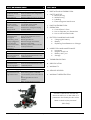
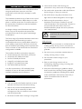
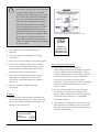
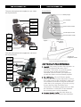
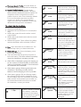
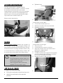
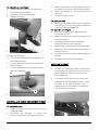
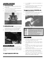
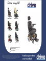
Feel free to enjoy life!
SUNFIRE PLUS GT
SUNFIRE PLUS EC
IMAGE GT
IMAGE EC
SUNFIRE GENERAL
GEO
US
UK
DE
Drive Medical Design & Manufacturing, NY 11050
Drive Medical Ltd, HX5 9JP
Drive Medical GmbH & Co. KG, D-88316 Isny
Part No. Z20945 (Rev C)
The team at Drive Medical develops its products to give our customers the freedom to live
independently. This encompasses their daily home life and provides them with the opportunity
to enjoy an outing with family and friends. Our goal is to develop a range that will provide
individuals with a chance to enjoy every day life.
fixed base powerchairs
owner’s handbook
QUICK REFERENCE GUIDE
CONTENTS
Problem: Limited range or low power showing
Causes:
Remedy:
Insufficient charge
Ensure batteries are charged for
in batteries
at least 12 hours.
Weak batteries
Replace batteries if error persists.
Problem: Batteries not charging
Causes:
Remedy:
No mains power
Try another mains socket
Loose connections
Check all connections
Blown fuse
Check fuse in charger and plug
Charger fault
Contact dealer.
1.
PREFACE AND INTRODUCTION
2. SAFETY NOTICE
• Before Driving
• Whilst Driving
• Labelling
• Electromagnetic Interference
3. PARTS INTRODUCTION
4. OPERATION
• Control Panel – Drive
• How to Operate your Powerchair
• How to set freewheel mode
Problem: Powerchair will not drive
Causes:
Remedy:
Freewheel levers
Ensure freewheel levers are in
disengaged
DRIVE position
Low battery power
Recharge batteries
Charger plugged in
Remove charger and restart
Circuit breaker
Reset circuit breaker
Joystick held whilst
Release joystick and do not hold;
powerchair is
restart powerchair
switched on
5. BATTERY CHARGING AND CARE
• Charging the battery
• Battery
• Replacing Drive Batteries or Charger
Problem: Only one wheel turns
Causes:
Remedy:
Only one freewheel
Ensure both freewheel levers are
lever engaged
in DRIVE position
Problem: Excessive motor noise
Causes:
Remedy:
Freewheel levers
Ensure both freewheel levers are
not fully engaged
in DRIVE position
Problem: Battery gauge flashes
Symptoms:
Remedy:
The powerchair has Ensure the joystick is released
diagnosed a fault
and switch the powerchair off and
on.
Recharge batteries if error
persists.
Refer to fault diagnosis guide
6. INSPECTION AND MAINTENANCE
• Inspection
• Regular Check List
• Battery and Tyres
• Storage
7. TROUBLESHOOTING
8. SPECIFICATION
9. WARRANTY
10. SERVICE RECORD
11. WARRANTY REGISTRATION
“Caution: Federal Law restricts this
device to sale by or on the order of a
practitioner licenced by the law of the
State in which he/she practices”
(USA Only)
Drive Image GT pictured
Drive Powerchair Range
Page 1
Z20945 (Rev C)
1. PREFACE AND INTRODUCTION
Please carefully read this owner’s handbook before
using the powerchair. Improper use of the
powerchair could result injury, damage or traffic
incidents.
This handbook includes a copy of the service record
and warranty information. Please keep it in a safe
place or with the powerchair. If someone else uses
the powerchair, provide them with this handbook
for their information.
As designs change some illustrations and pictures
herein may not correspond to the powerchair
purchased. We reserve the right to make design
modifications.
• Use extreme caution when driving your
powerchair in busy areas such as shopping malls.
• Do not drive the powerchair under the influence
drink or drugs, or when you are tired.
• Be careful when using the powerchair in low
light. It has not been designed for use at night.
• Before using the powerchair in busy or
hazardous environments, familiarise yourself
with the operation of the powerchair. Practice in
an open and safe area which is free from
hazards and other people. Use a low speed for
your initial practice.
Always remain in seat whilst using the
powerchair. Do not stand on the
footplate.
The Drive range of powered wheelchairs have been
designed and manufactured to provide a
comfortable and secure yet affordable solution for
some mobility requirements. All Drive powerchairs
have a fixed base (not folding) with a separate seat.
There a number of mid-wheel and rear-wheel drive
configurations available.
Whilst Driving
• Do not use your powerchair on surfaces that are
muddy, gravelly, bumpy, narrow, snowed over,
icy; or on towpaths near to canals which are not
guarded.
• Do not use your powerchair outside when it is
raining, snowing, misty or windy.
The models in the Drive powerchair range are:
• Sunfire General rear wheel drive powerchair
• Sunfire Plus GT RWD powerchair
• Sunfire EC RWD powerchair
• Image EC mid wheel powerchair
• Image GT mid wheel powerchair
• Geo Indoor RWD powerchair
• Do not make erratic turnings on your
powerchair.
• Bear in mind driving motions such as
accelerating, stopping, turning, reversing, and
the effect of gradients.
Your Drive powerchair is CE marked by Drive
Medical, who are an ISO 9001 and ISO 13485
certified medical device manufacturer.
• Slow down when driving on gradients. Always
lean forward when climbing a steep gradient. Do
not travel on gradients exceeding those stated
in the specification. Most access ramps are 5º
which is a suitable incline for all Drive
powerchairs.
2. SAFETY
Before Driving
• The user needs to be familiar with the use and
operation of this powerchair before driving.
• Ride on the pavement and pedestrian areas
only. Never ride on motorways or dual
carriageways. Only use roads to cross to other
side of the pavement.
• Be aware of traffic when crossing or using roads.
Drive Powerchair Range
Page 2
Z20945 (Rev C)
When climbing an incline, try to keep your
powerchair moving. If you must stop, start
up again slowly, and then accelerate
cautiously. When driving down an incline,
do so slowly and in the forward direction
only. If your powerchair starts to move
faster than you anticipated or desired,
allow the chair to come to a complete
stop by releasing the joystick. Push the
joystick slightly forward and continue
travelling slowly down the incline. When
climbing an incline, do not zigzag or drive
at an angle up the face of the incline.
Always drive your Drive straight up the
incline. This greatly reduces the possibility
of a tip or a fall.
Above: Located by freewheel levers on rear
WARNING:
EMI
REFER TO
OPERATORS
MANUAL FOR
INFORMATION
• Do not drive on roads with large drops or
potholes.
• The powerchair is not suitable for carrying
passengers.
Above: Located on rear
• Do not use the powerchair to carry heavy goods.
• Do not use a mobile phone or other wireless
communication devices whilst driving. Always
stop somewhere suitable and switch off the
powerchair before using the phone.
Electromagnetic Interference
• Powerchairs may be susceptible to
electromagnetic interference (EMI) from sources
such as mobile phones, walkie-talkies, TV and
radio broadcast stations and amateur radio sets.
In some cases, there is a risk this interference
may cause involuntary movement of the
powerchair. The powerchair has been tested and
passed to withstand interference to a level of
20V per metre.
• Do not set in freewheel mode when driving,
especially on a gradient. Ensure that the
powerchair’s automatic brakes are applied
before use.
• Do not exceed the weight limit of the
powerchair.
• Be aware that the above sources may cause
involuntary movement due to EMI. Exercise
caution whilst using the aforementioned devices
and avoid close proximity to TV and Radio
broadcast stations.
Labelling
• Please carefully read all labels applied to the
powerchair before driving. For future reference,
do not remove them from the powerchair. The
labels are also shown here:
• The addition of components or accessories may
effect the EMI susceptibility of the powerchair.
Do not fit accessories other than Drive Medical
authorised accessories.
Product Code: __________
Drive Medical HX5 9JP
Serial #:
Max User Mass ___kg
Above: Located on rear
Drive Powerchair Range
Page 3
Z20945 (Rev C)
3. PARTS INTRODUCTION
4. PARTS INTRODUCTION
Control Panel
The parts description below applies to rear wheel
drive powerchairs:
Battery Gauge
HEAD REST
On / Off Button
SEAT BACK
REST
Horn
ARM REST
Speed / Profile Indicator
CONTROLLER
Increase Speed / Profile
SEAT BASE
SEAT
ROTATE
LEVER
Decrease Speed / Profile
SHROUD
Joystick
REAR
(DRIVE)
WHEEL
FRONT
(CASTOR)
WHEEL
Control Panel
(see previous
diagram)
FOOT PLATE
The parts description below applied to mid wheel
drive powerchairs:
Charger and
Programmer socket
HEAD REST
Joystick Control Panel shown above
SEAT BACK
REST
HOW TO OPERATE YOUR POWERCHAIR
CONTROLLER
1. Joystick. The primary function of the joystick is to
control the speed and direction of the
wheelchair. The further you push the joystick
from the center position the faster the
wheelchair will move. When you release the
joystick the brakes are automatically applied.
ARM REST
SEAT BASE
SEAT
ROTATE
LEVER
2. On / Off button. The on/off button applies
power to the control system electronics, which in
turn supply power to the wheelchair’s motors. Do
not use the on/off button to stop the wheelchair
unless there is an emergency. (If you do, you may
shorten the life of the wheelchair drive
components). The battery gauge shows you that
the wheelchair is switched on. It also indicates
the operating status of the wheelchair.
FOOT PLATE
FRONT
(CASTOR)
WHEEL
MID (DRIVE)
WHEEL
REAR
(ANTI TIP)
WHEEL
3. Increase Speed / Profile. Press this button to
increase the maximum speed of the wheelchair.
Drive Powerchair Range
Page 4
Z20945 (Rev C)
4. Decrease Speed / Profile. Press this button to
decrease the maximum speed of the wheelchair.
5. Speed / Profile Indicator. This shows the
maximum speed of the wheelchair. The more
LEDs are lit, the faster the maximum speed. The
wheelchair can be configured to use drive
profiles. However, this is not included by default.
For more information about drive profiles,
contact your dealer. If the speed indicator
ripples, this means the wheelchair is locked. By
default the locking function is disabled.
2 Bar
3 Bar
4 Bar
To unlock / lock the wheelchair:
• Switch the wheelchair on
• Hold down the on/off button for 1 second (lock
only)
• Deflect the joystick forwards until the control
system bleeps
• Deflect the joystick backwards until the control
system bleeps
• Release the joystick. There will be a long bleep
and the wheelchair will be unlocked / locked.
5 Bar
6 Bar
6. Horn. Press this button to sound the horn. The
horn will stop when you release the button.
7. Battery Gauge. This shows the battery power
level of the wheelchair.
7 Bar
• The more LEDs that are lit, the more power is
left in the battery. The LEDs will be lit constantly
when the wheelchair is operating normally.
• If the LEDs on the battery gauge are stepping up
(i.e. the number of LEDs lit quickly increases then
resets to 1), the battery charger is connected and
the wheelchair drive inhibited.
8 Bar
• If the battery gauge is flashing slowly then the
wheelchair is operating normally, but the
batteries need recharging as soon as possible.
9 Bar
• If the battery gauge LEDs are flashing rapidly
this indicates a fault with the wheelchair. If you
have a problem with your wheelchair consult the
table overleaf. If the problem persists after you
have followed the advice herin then restarted
the wheelchair, contact your dealer.
1 Bar
Drive Powerchair Range
The battery needs charging
or there is a bad connection
to the battery. Check the
connections to the battery.
If the connections are good,
try charging the battery.
Page 5
10 Bar
10 Bar +
Speed
The left hand motor has a
bad connection. Check the
connections to the left hand
motor.
The left hand motor has a
short circuit to a battery
connection. Contact your
service agent.
The right hand motor has a
bad connection. Check the
connections to the right
hand module.
The right hand motor has a
short circuit to a battery
connection. Contact your
service agent.
The wheelchair is being
prevented from driving by
an external signal. The
exact cause will depend on
the type of wheelchair you
have, one possibility is the
battery charger is
connected.
A joystick fault is indicated.
Make sure that the joystick
is in the centre position
before switching on the
control system.
A control system fault is
indicated. Make sure that
all connections are secure.
The parking brakes have a
bad connection. Check the
parking brake and motor
connections. Make sure the
control system connections
are secure.
An excessive voltage has
been applied to the control
system.
This is usually caused by a
poor battery connection.
Check the battery
connections.
This is where the Speed
Indicator and 10 bars are lit.
A communication fault is
indicated. Make sure that
joystick cable is securely
connected and not
damaged.
Z20945 (Rev C)
•
EXTENDABLE CONTROL BRACKET
Release lever
Your Drive powerchair is equipped with an
extendable controller bracket. To extend or retract
the bracket, first slacken the knob located
underneath the armrest (shown by arrow) and then
reposition the control as required, Retighten the
knob to secure. The armrests also flip up to allow
improved access to tables, desks, etc.
Please see the photo below.
•
To adjust the armrest width:
• Loosen the tri-knobs (arrow 2).
• Slide the armrests to the required width.
• Retighten tri-knobs.
BRAKING
•
Electromagnetic braking: Release the joystick on
the controller and the electromagnetic brakes will
automatically operate and the powerchair will stop.
At first this can be a strange sensation which is why
we recommend we an initial practice session with
the powerchair as described in the Safety Notice.
To adjust the armrest angle
• Lift up armrest
• Loosen the jam nut (arrow 3 below)
• Adjust the socket screw up or down to the
desired arm angle position.
• Retighten the jam nut
• To determine the same angle for the opposite
armrest, measure the protrusion or count up
the number of threads on the bolt.
• Repeat process for other armrest
WARNING!
Putting the motors in to freewheel mode
also disengages the brakes. When on a
gradient never switch the powerchair in
to freewheel mode as the
electromagnetic brakes will not be
applied. This may result in injury.
3
HOW TO ADJUST THE SEAT
To adjust the seat back angle:
• Pull up the seat back recline lever (arrow 1).
• Adjust the seat back to the required
position.
Drive Powerchair Range
Page 6
•
Z20945 (Rev C)
•
To adjust the armrest height
• Push the plastic button on the side of the
armrest (see photo below)
• Reposition to the desired height
• Release the button
•
•
Slacken the tri-knob securing the seat post in
the seat post receiver on the powerchair base
Unlock the locking pin and remove from the
seat post.
Lift up the seat to remove
To install the seat:
• Reverse the procedure above ensuring that the
seat locking pin is securely locked and that the
tri-knob is sufficiently tightened
To adjust the seat height:
• Remove the seat, as described above and
remove the shroud.
• Release the seat post camlock mounted on the
seat post receiver.
• Disengage and remove the seat height
adjustment bolt from the seat post.
• Reposition the seat post at the desired height.
• Reinsert the bolt in to the seat post and secure
with the nyloc nut.
• Lock the seat post in position with the seat post
camlock.
• Reinsert the seat, as described above.
•
To adjust the headrest
• To raise the headrest, lift the headrest up to
the required position
• To lower the headrest, push the release tab
(arrow 4 below)
• Lower the headrest to the required position
and release the tab
ROTATING THE SEAT
•
The seat can rotate 180°, and the seat locks at
45° intervals. This allows the user to swivel the
seat to the left or right for easier access to
desks, tables, etc.
•
To rotate the seat, first push up on the seat
rotation lever. Whilst holding the lever, swivel
the seat in to the required position. Then
release the lever and continue swiveling the
seat until it locks in position.
4
•
REMOVAL AND HEIGHT ADJUSTMENT OF SEAT
To remove the seat:
• Switch the Drive off and ensure it is not in
freewheel mode
• Disconnect the controller or remove the
armrest on which the controller is mounted
Drive Powerchair Range
Page 7
•
Z20945 (Rev C)
ADJUSTING THE FOOT PLATE
•
To adjust the footrest angle
• You can adjust the angle of the footrest with a
M6 allen key
• Turn the setscrew (arrow 1 below) clockwise to
raise the front of the footrest
• Turn the setscrew (arrow 1 below) anticlockwise
to lower the front of the footrest
•
•
It is advisable to ensure the powerchair is
switched off
Turn the freewheel lever on both motors to the
DRIVE position (see photo below)
Switch the powerchair on and use as normal
To engage the powerchair in FREEWHEEL mode
• Switch off the powerchair
• Turn the freewheel lever on both motors to the
FREEWHEEL position (see photo below)
•
Manoeuvre the powerchair manually
•
To adjust the footrest height
• Remove the nut and bolt securing the footplate
bracket (shown by arrow in the photograph).
• Adjust the bracket to the required height.
• Reattach the bracket to the powerchair using
the nut and bolt.
•
WARNING!
Putting the motors in to freewheel mode
also disengages the brakes. When on a
gradient never switch the powerchair in
to freewheel mode as the
electromagnetic brakes will not be
applied. This may result in injury.
CIRCUIT BREAKERS
•
Your Drive powerchair has a circuit breaker
protruding through the shroud cover.
•
In the unlikely event of a short circuit or heavy
overload, all power to your powerchair will be
shut off.
•
To reset the circuit breaker, press the circuit
breaker button. The circuit breaker will then
reset after a few minutes.
•
If the powerchair continues to shut down after
resetting contact your Drive Medical dealer.
•
With some shroud styles the circuit breaker is
recessed in to the shroud and covered by a
rubber flap. To gain access to the circuit
breaker simply lift up the rubber flap.
•
SETTING FREEWHEEL MODE
For your convenience, your Drive powerchair is
equipped with a freewheel lever. This allows you to
disengage the drive motors and electromagnetic
brakes so you can manoeuvre the powerchair
manually.
To engage the powerchair in DRIVE mode:
Drive Powerchair Range
Page 8
Z20945 (Rev C)
5. BATTERY CHARGING AND CARE
To Charge the Powerchair
1.
2.
For Off-board chargers (UK). Plug the round
Plug the charger’s power cord in to the mains.
3.
connector on the charger in to the socket on
the front of the joystick controller
For On-board chargers (USA). Plug the mains
lead in to the socket on the scooter body.
Switch on the plug socket at the mains.
Charger Light
• The charger light will illuminate orange to
indicate the batteries are charging. The
charging duration is about 8 hours, however a 12
hour charge is recommended for optimum
performance. The orange light will turn green
when charging is 95% complete.
Ensure that the charger is removed from
the mains and the powerchair after
charging. Failure to do this may flatten the
battery.
Suggestions
1. Do not disconnect the charger cord
until charging is completed and the light
is lit Green.
2. When fully charged the battery charger
will still trickle charge the battery for
optimum range.
3. Even when not in use, the powerchair
should be charged at least every week
to ensure battery longevity.
4. Ambient temperature will effect
charging time. Charging time will be
longer in cold environments.
5. The batteries carry a 1 year warranty
which covers manufacturing defects
only. It does not cover battery faults as
result of not following the guidelines
herein.
Drive Powerchair Range
Page 9
Warning
1. Only use the charger supplied with the
powerchair. Using the wrong type of
charger may cause damage. Never
disassemble or modify the powerchair.
2. Always charge the powerchair in a well
ventilated space. Avoid direct sunlight
or contact with water and moisture.
3. Do Not charge or operate the
powerchair in temperatures below 10ºC or above 50ºC. Do not expose the
battery pack to these temperatures.
About the Batteries
• The batteries require charging every week to
ensure battery longevity.
• The batteries supplied by Drive Medical are
classified as safe for air transport under IATA
special provision A67.
Battery Care
1. You should recharge the batteries after
each time the powerchair is used to ensure
maximum battery range. The batteries
should be charged at least once a week
even if the powerchair is not used.
2. After charging or replacing a new battery,
drive the powerchair for a short period to
ensure battery capacity is sufficient.
3. In cold environments, the battery may
respond more slowly and range will be
reduced.
4. When driving on a gradient, the battery
gauge will fluctuate. This is a normal
occurrence.
5. Battery range is reduced when driving up
gradients or on rough terrain, as the
powerchair uses more power.
6. The batteries should not be charged for
more than 24 hours.
Battery Replacement
It is natural for the battery capacity to reduce with
time, even if the battery is charged as directed
above. When the battery range is about half of its
peak performance we recommend that the
batteries are changed. Continuing to use an old
battery will result in a rapid reduction in the range
of the powerchair and can cause excessive wear
and tear on other parts of the powerchair.
Z20945 (Rev C)
6. INSPECTION AND MAINTENANCE
a. Weekly Checking
Check the following items weekly or before driving.
If you find anything abnormal contact your Drive
Medical Dealer for further inspection or advice.
• Arms. Check they are secure and flip up easily
d.
Cleaning
•
The powerchair should be cleaned periodically,
especially if you tend to drive on sand, gravel
or other adverse environments.
•
Use a soft, wrung dry cloth to keep your
powerchair clean and dust free. Use a damp
cloth and mild detergent to clean the
powerchair.
• Seat and Back. Check for rips or sagging. Ensure
seat positively locks in position and swivels
freely.
• Motor. Check for any abnormal noise and
electromagnetic brakes work correctly.
Warning
• Do not use a hose pipe or splash water
directly on to the powerchair.
• Do not use petrol, solvents or vaporising
solutions as these many damage body
panels. Do not use wax
• Ensure the charger is unplugged and the
powerchair switched off before cleaning
the powerchair.
• Freewheel Lever. Ensure they works correctly.
• Horn. Check the horn sounds when button
pressed.
• Tyres. Check tyre tread depth and for any signs
of damage such as cracking.
• Front (Castor) Wheels. Check they swivel easily,
and there is no vibration when going forward.
b. Service Record
To ensure your powerchair is correctly serviced take
it to your Drive Medical dealer for regular service.
We recommend that powerchairs are serviced at
least annually, and your dealer may charge a fee
for this.
A copy of the service record is at the back of this
handbook.
Even if the powerchair has not been used,
it should still be serviced annually.
c.
•
Batteries and Tyres
For information on the batteries, please read
section 5 on Battery Charging and Care.
•
Tyre condition will be affected by how you
drive the powerchair and what terrain it is
driven on.
•
Some models come with solid tyres which are
puncture free, so there is no need to check tyre
pressure.
•
On models with pneumatic tyres, check tyre
pressure regularly. The maximum tyre pressure
is stated on the side wall of the tyre.
Drive Powerchair Range
Page 10
e.
Storage
•
Ensure the powerchair is stored with the seat
set in the forward position, the powerchair
switched off and charger disconnected. Ideally
the joystick controller should also be
unplugged to prevent battery drain.
Store the powerchair in environments which
are free from direct sunlight and water or
moisture.
f.
Moving About
1.
Switch off the powerchair and dismount from
the powerchair.
2.
Lift the powerchair by the chassis only.
3.
For your safety ask for help if required. You will
need two or more people when moving or
lifting the powerchair as a whole.
Never lift the powerchair by the bumpers or
body panels, as this can cause injury or
damage.
Z20945 (Rev C)
TROUBLESHOOTING GUIDE
Problem: Limited range or low power showing
Causes:
Remedy:
Insufficient charge
Ensure batteries are charged for
in batteries
at least 12 hours.
Weak batteries
Replace batteries if error persists.
Problem: Batteries not charging
Causes:
Remedy:
No mains power
Try another mains socket
Loose connections
Check all connections
Blown fuse
Check fuse in charger and plug
Charger fault
Contact dealer.
Problem: Powerchair will not drive
Causes:
Remedy:
Freewheel levers
Ensure freewheel levers are in
disengaged
DRIVE position
Low battery power
Recharge batteries
Charger plugged in
Remove charger and restart
Circuit breaker
Reset circuit breaker
Joystick held whilst
Release joystick and do not hold;
powerchair is
restart powerchair
switched on
Problem: Only one wheel turns
Causes:
Remedy:
Only one freewheel
Ensure both freewheel levers are
lever engaged
in DRIVE position
Problem: Excessive motor noise
Causes:
Remedy:
Freewheel levers
Ensure both freewheel levers are
not fully engaged
in DRIVE position
Problem: Battery gauge flashes
Causes:
Remedy:
The powerchair has Ensure the joystick is released
diagnosed a fault
and switch the powerchair off and
on.
Recharge batteries if error
persists.
Refer to fault diagnosis guide on
page 5
A copy of this troubleshooting guide is also included
on page 1 of this handbook.
Drive Powerchair Range
Page 11
Z20945 (Rev C)
8. SPECIFICATION
Rear Wheel Drive Powerchairs
SADMERC Code Group
Dimensions (cm) /
L x W x H (in)
Total weight (kg / in)
Carry weight (kg / in)
Battery
Motor
Charger
Castor wheel
Drive wheel
Climbing angle
Kerb climbing ability
Ground clearance
Cruising range
Turning radius (cm / in)
Max. user weight
Max. speed (mile / km)
Sunfire Plus EC
K0823
95 x 60 x 110cm
37.4 x 24 x 43.3
96kg / 212lbs
Sunfire Plus GT
K0823
103.5 x 66 x 113.5
41 x 26 x 45
91kg / 201lbs
Sunfire General
K0825
103 x 63.5 x 112
41 x 25 x 44
100kg / 220lbs
U1 (typically 36ah)
270W
5A OFF BOARD
8” (20cm) diameter
10” (25cm) diameter
8°
4cm / 1.6”
6.8cm / 2.7”
24~32km (15 – 20 miles)
79cm / 31”
136kg / 300lbs
4mph / 6.4kph
U1 (typically 36ah)
350W
5A OFF BOARD
8” (20cm) diameter
10” (25cm) diameter
8°
4cm / 1.6”
5.3cm / 2.1”
24~32km (15 – 20 miles)
83cm / 32.7”
136kg / 300lbs
4mph / 6.4kph
Typically 50ah
450W
5A OFF BOARD
9” (23cm) diameter
13” (34cm) diameter
8°
4cm / 1.6”
8cm / 3.1”
24~32km (15 – 20 miles)
72cm / 28.3”
180kg / 400lbs
4mph / 6.4kph
Image GT
K0823
107 x 63.5 x 105.5
42.1 x 25 x 42
108kg / 238lbs
Image EC
K0823
106 x 62.5 x 110
42 x 25 x 43
87kg / 192lbs
Geo
K0814
85 x 56 x 55.5
33.5 x 22 x 21.8
45.9kg / 101lbs
U1 (typically 36ah)
450W
5A OFF BOARD
6” (15cm) diameter
10” (25cm) diameter
8°
4cm / 1.6”
5cm / 2.2”
24~32km (15 – 20 miles)
77cm / 30.3”
160kg / 350lbs
4mph / 6.4kph
U1 (typically 36ah)
200W
4A OFF BOARD
6” (15cm) diameter
10” (25cm) diameter
8°
4cm / 1.6”
3.5cm / 1.3”
24~32km (15 – 20 miles)
70cm / 28”
136kg / 300lbs
4mph / 6.4kph
12Ah
180W
1.8A OFF BOARD
6” (15cm) diameter
8” (20cm) diameter
6°
2cm / 0.8”
6.8cm / 2.7”
8~10km (4-6 miles)
43cm / 17”
115kg / 250lbs
4mph / 6.4kph
Mid Wheel Drive Powerchairs and Geo Indoor Chair
SADMERC Code Group
Dimensions (cm) /
L x W x H (in)
Total weight (kg / in)
Carry weight (kg / in)
Battery
Motor
Charger
Castor wheel
Drive wheel
Climbing angle
Kerb climbing ability
Ground clearance
Cruising range
Turning radius (cm / in)
Maximum user weight
Maximum speed
Remark : The manufacturer reserves the right to modify the specification if necessary. The final specification is
subject to the individual powerchair you purchase from your dealer.
Note:
Maximum driving distance is based on an ambient temperature of 20ºC, a 75kg driver, a brand new fully
charged battery, a constant driving speed at 4mph with 70% battery power discharged.
The Geo Indoor Powerchair has its own Handbook, and is not covered by this handbook
Battery specifications supplied are subject to change, as batteries are not supplied as standard by Drive
Medical.
Drive Fixed Base Powerchairs
Page 12
Z20945 (Rev C)
Note:
VIN NUMBER
To ensure the correct after sales service and
warranty service support, please write down the
powerchair serial number. The serial number is
located on the back right-hand side of the frame.
VIN Number
Motor S/No.
This guarantee is not transferable
4. Any repaired or replaced parts will be covered
by this warranty for the balance of the warranty
period on the powerchair.
5. Consumable items supplied will not generally be
covered during the normal warranty period
unless such items require repair or replacement
clearly as a direct result of a manufacturing or
material defect.
Such items include (among others):
upholstery, tyres and batteries.
Controller
S/No.
6. The above warranty conditions apply to brand
new powerchair purchased at the full retail
price. If you are unsure whether your power
chair is covered, check with the service agent.
Also, note your Drive Medical dealer below:
7. Under normal circumstances, no responsibility
will be accepted where the powerchair has
failed as a direct result of:
Dealer
Address
a) The powerchair part not having been
maintained in accordance with the
manufacturer’s recommendations.
b) Failure to use the manufacturer’s specified
parts
Postcode
Telephone
c) The powerchair or part having been
damaged due to neglect, accident or
improper use
WARRANTY
d) The powerchair or part having been
altered from the manufacturer’s
specifications or repairs having been
attempted before the service agent is
notified
There is a comprehensive twelve-month warranty from
the date on which your new powerchair is delivered. The
warranty covers the powerchair for repairs or
replacement during this period. For more detail, please
see the Warranty Conditions below.
Warranty Conditions:
1.
Any work or replacement part installation must
be carried out by an authorized Drive Medical
dealer / service agent.
2. To apply the warranty should your powerchair
require attention please contact the designated
service agent listed below.
3. Should any part of the powerchair require
repair or full or part replacement, as a result of
a manufacturing or material defect within
twelve months of receiving the powerchair,
replacement parts will be supplied free of
charge.
Drive Powerchair Range
Page 13
Please note your local service agent’s contact
details in the previous box. In the event of your
powerchair requiring attention, contact them and
give all relevant details so they can act quickly.
The manufacturer reserves the right to alter without
notices any weights, measurements or other
technical data shown in this manual. All figures,
measurements and capacities shown in this manual
are approximate and do not constitute
specifications.
Z20945 (Rev C)
APPENDIX : SERVICE RECORD
YEAR
1
2
3
4
5
6
YEAR
Service Dates
Service Dates
Controller
Upholstery
On/off switch
Seat
Joystick
Back
Braking
Armrests
Recharge point
Electrics
Batteries
Connections
condition
Levels
Utility tray
Connections
Test run
Discharge test
Forwards
Wheels and
Reverse
Wear
stop
Pressure
Left turn
Bearings
Right turn
Wheel nuts
Slope test
Motors
Over obstacles
Wiring
List Items repaired
1
2
3
4
5
6
Noise
Connections
Brake
Brushes
Chassis/Footrest
Condition
Footrest
Drive Powerchair Range
Page 14
Z20945 (Rev C)
………………………………………………………..………………………….…………………………….……………………………....
WARRANTY REGISTRATION
Please detach from the line (left) and type or print to fill out the form, and send to:
UK:
Drive Medical Ltd, Ainleys Industrial Estate, Elland, UK HX5 9JP
USA:
Drive Medical, 99 Seaview Boulevard, Port Washington, NY 11050
Serial#
.......................................................... Date Purchased ……….… / ……….… /……….…
Owner Name
…………………………………………………….…………………………………………………………………….
Address
……………………….………………………………………………………………………………………………….
City
………………………………………………… Zip or Postcode ………………………………………...
Additional Required Owner Information
Please indicate your understanding of your powered product by completing the following
information
……………… My dealer has instructed me on how to operate my powerchair.
I have read and fully understand:
……………… Owner’s Handbook, especially the sections on operating insutrctions, safety
guidelines, maintenance and battery charging instructions.
………………. Powerchair Warranty
Battery Instructions – only sealed lead acid or gel cell type batteries should be used.
Batteries must also be sealed, deep cycle and maintenance free or battery will hinder
vehicle performance and void the warranty.
Signature ……………………………………………….. Dealer Name ………………………………………………………………..
Telephone ……………………………………………… Dealer Phone …………………………………………………………….…
Email …………………………………………………………………………………………………………………………………………………….
Comments:
…………………………………………………………………………………………………………………………………
…………………………………………………………………………………………………………………………………………………………………
…………………………………………………………………………………………………………………………………………………………………
…………………………………………………………………………………………………………………………………………………………………
Drive Powerchair Range
Page 15
Z20945 (Rev C)