1
ALLEN&HEATH
GL4800
USER GUIDE
Publication AP6150
Limited One Year Warranty
This product is warranted to be free from defects in materials or workmanship for
a period of one year from the date of purchase by the original owner.
To ensure a high level of performance and reliability for which this equipment has
been designed and manufactured, read this User Guide before operating. In the
event of a failure, notify and return the defective unit to Allen & Heath Limited or
its authorised agent as soon as possible for repair under warranty subject to the
following conditions
Conditions Of Warranty
1. The equipment has been installed and operated in accordance with the
instructions in this User Guide
2. The equipment has not been subject to misuse either intended or accidental,
neglect, or alteration other than as described in the User Guide or Service
Manual, or approved by Allen & Heath.
3. Any necessary adjustment, alteration or repair has been carried out by Allen
& Heath or its authorised agent.
4. This warranty does not cover fader wear and tear.
5. The defective unit is to be returned carriage prepaid to Allen & Heath or its
authorised agent with proof of purchase.
6. Units returned should be packed to avoid transit damage.
In certain territories the terms may vary. Check with your Allen & Heath agent for
any additional warranty which may apply.
This product complies with the European Electromagnetic
Compatibility directives 89/336/EEC & 92/31/EEC and the
European Low Voltage Directives 73/23/EEC & 93/68/EEC.
This product has been tested to EN55103 Parts 1 & 2 1996 for use in
Environments E1, E2, E3, and E4 to demonstrate compliance with the
protection requirements in the European EMC directive 89/336/EEC.
During some tests the specified performance figures of the product
were affected. This is considered permissible and the product has
been passed as acceptable for its intended use. Allen & Heath has a
strict policy of ensuring all products are tested to the latest safety and
EMC standards. Customers requiring more information about EMC
and safety issues can contact Allen & Heath.
NOTE: Any changes or modifications to the console not approved by
Allen & Heath could void the compliance of the console and therefore
the user’s authority to operate it.
GL4800 User Guide AP6150 Issue 1
Copyright © 2005 Allen & Heath Limited. All rights reserved
Manufactured in the United Kingdom by
ALLEN&HEATH Limited
Kernick Industrial Estate, Penryn, Cornwall, TR10 9LU, UK
http://www.allen-heath.com
2
GL4800 User Guide
Important Safety Instructions
WARNINGS -
Read the following before proceeding :
CAUTION
ATTENTION: RISQUE DE CHOC ELECTRIQUE – NE PAS OUVRIR
Read instructions:
Read and retain these safety and operating
instructions for future reference. Adhere to all warnings printed here and
on the console. Follow the operating instructions printed in this User
Guide.
Do not remove cover:
Operate the console with its underside
cover correctly fitted. Disconnect mains power by unplugging the power
cord if the cover needs to be removed for setting internal options. Refer
this work to competent technical personnel only.
Power sources: Connect the console to a mains power outlet only of
the type described in this User Guide and marked on the rear panel. Use
the power cord with sealed mains plug appropriate for your local mains
supply as provided with the console. If the provided plug does not fit into
your outlet consult your service agent for assistance.
Power cord routing:
Route the power cord so that it is not likely
to be walked on, stretched or pinched by items placed upon or against it.
Grounding:
Do not defeat the grounding and polarisation means
of the power cord plug. Do not remove or tamper with the ground
connection in the power cord.
WARNING: This equipment must be earthed.
Water and moisture:
To reduce the risk of fire or electric shock
do not expose the console to rain or moisture or use it in damp or wet
conditions. Do not place containers of liquids on it which might spill into
any openings.
Ventilation:
Do not obstruct the rear and top ventilation slots or
position the console where the air flow required for ventilation is impeded.
If the console is to be operated in a flight case, plinth or other furniture
ensure that it is constructed to allow adequate ventilation.
Heat and vibration:
Do not locate the console in a place
subject to excessive heat or direct sunlight as this could be a fire hazard.
Locate the console away from any equipment which produces heat or
causes excessive vibration.
Servicing:
Switch off the equipment and unplug the power cord
immediately if it is exposed to moisture, spilled liquid, objects fallen into
the openings, the power cord or plug become damaged, during lightning
storms, or if smoke, odour or noise is noticed. Refer servicing to qualified
technical personnel only.
Installation:
Install the console in accordance with the
instructions printed in this User Guide. Do not connect the output of power
amplifiers directly to the console. Use audio connectors and plugs only for
their intended purpose.
GL4800 User Guide
3
General Precautions
Damage
To prevent damage to the controls and cosmetics avoid
placing heavy objects on the control surface, scratching the surface with
sharp objects, or rough handling and vibration.
Environment Protect from excessive dirt, dust, heat and vibration
when operating and storing. Avoid tobacco ash, smoke, drinks spillage,
and exposure to rain and moisture. If the console becomes wet, switch off
and remove mains power immediately. Allow to dry out thoroughly before
using again.
Cleaning
Avoid the use of chemicals, abrasives or solvents. The
control panel is best cleaned with a soft brush and dry lint-free cloth. The
faders, switches and potentiometers are lubricated for life. The use of
electrical lubricants on these parts is not recommended. The fader and
potentiometer knobs may be removed for cleaning with a warm soapy
solution. Rinse and allow to dry fully before refitting them.
Lifting To avoid injury to yourself or damage to the equipment take
care when lifting, moving or carrying the console.
Transporting The console may be transported as a free-standing unit
or mounted in a purpose built flight case. We recommend that the console
is surrounded by shock absorbent foam to protect it from damage during
transit. Always use adequate packing if you need to ship the unit. Protect
the controls to avoid damage when moving the console.
Hearing To avoid damage to your hearing do not operate any sound
system at excessively high volume. This also applies to any close-to-ear
monitoring such as headphones and IEM transducers.
Continued
exposure to high volume sound can cause frequency selective or wide
range hearing loss.
82
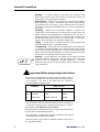
Important Mains plug wiring instructions.
The console is supplied with a moulded mains plug fitted to the AC
mains power lead. Follow the instructions below if the mains plug has
to be replaced. The wires in the mains lead are coloured in
accordance with the following code:
WIRE COLOUR
TERMINAL
European
USA/Canada
L
LIVE
BROWN
BLACK
N
NEUTRAL
BLUE
WHITE
E
EARTH GND
GREEN & YELLOW
GREEN
The wire which is coloured Green and Yellow must be connected to
the terminal in the plug which is marked with the letter E or with the
Earth symbol. This appliance must be earthed.
The wire which is coloured Blue must be connected to the terminal in
the plug which is marked with the letter N.
The wire which is coloured Brown must be connected to the terminal
in the plug which is marked with the letter L.
Ensure that these colour codes are followed carefully in the event of
the plug being changed.
4
GL4800 User Guide
Introduction
Welcome to the Allen & Heath GL4800, the latest generation of the popular GL series of
multi-function audio mixing consoles. We have tried to keep this user guide brief and to the
point. Please read it fully before starting. Included is information on installing, connecting
and operating the console, panel drawings, system block diagram, technical specification
and cue sheets. For further information on the basic principles of audio system engineering,
please refer to one of the specialist publications and resources available from bookshops,
audio equipment dealers and the Internet.
Whilst we believe the information in this guide to be reliable we do not assume
responsibility for inaccuracies. We also reserve the right to make changes in the interest of
further product development.
We are able to offer further product support through our world-wide network of approved
dealers and service agents. You can also access our Web site on the Internet for
information on our full product range, our company pedigree, assistance with your
technical queries, our contact details or simply to chat about matters audio. To help us
provide the most efficient service please keep a record of your console serial number, and
date and place of purchase to be quoted in any communication regarding this product.
www.allen-heath.com
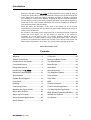
Contents
Warranty ................................................ 2
LR Section............................................26
General Precautions.............................. 4
Mono and Master Section ...................27
Introduction to this Guide...................... 5
The Mute System.................................30
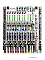
Front Panel Layout ................................ 6
Mute Groups ........................................32
Range and Options ............................... 7
Mute Safes ...........................................35
Introducing the GL4800 ....................... 8
Mute Snapshots...................................36
Dimensions and Weights .................... 10
The Snapshot Display .........................37
Specifications ...................................... 11
Solo-In-Place .......................................40
System Block Diagram........................ 12
Solo Safes............................................41
Connectors .......................................... 14
MIDI......................................................42
Earthing ............................................... 17
Technical Support ...............................46
Connecting Power............................... 18
Front-of-House Application .................48
Matching the Signal Levels ................. 19
On-Stage Monitor Application .............52
Mono Input Channel............................ 20
Multi-Speaker System Application ......55
Stereo Input Channel .......................... 22
Internal Link Options ...........................56
Stereo Channel Applications............... 23
Cue Sheets ..........................................57
Group Section ..................................... 24
GL4800 User Guide
5
LAMP
LAMP
+48V
-20
40
LINE MIC
50
6
-14
PAD
30 10
GAIN
LEV
-20
-15
-10
-30
-5
LEV
-20
-15
-10
-30
-5
0dB
GL4800
MIC
LINE
0dB
20
-10
-30
POLARITY
-10
10
-15
LEV
-20
-10
-30
-5
0dB
-15
LEV
-20
-10
-30
-5
0dB
-15
LEV
-20
-10
-30
-5
0dB
-15
+48V
LEV
2TRK RETURN
-5
0dB
0dB
ON
ON
ON
ON
ON
ON
AFL
AFL
AFL
AFL
AFL
AFL
+5
MULTI FUNCTION AUDIO MIXING CONSOLE
OUT REV
OUT REV
OUT REV
OUT REV
OUT REV
OFF
POST
PRE
7kHz
3k
-20
10k
-15
20kHz
POST
PRE
OUTPUT
TRIM
-20
-10
-30
2kHz
POST
PRE
OUTPUT
TRIM
-20
-10
-15
OUTPUT
TRIM
-20
POST
PRE
OUTPUT
TRIM
-20
-10
POST
PRE
OUTPUT
TRIM
-20
-10
POST
PRE
OUTPUT
TRIM
-20
-10
POST
PRE
OUTPUT
TRIM
-20
-10
POST
PRE
POST
PRE
1
Q
2
3k
1k
5k
7k
500Hz
15k
-15
ENABLE
HM
POLARITY
(R)
STEREO
PFL
REVERSE
ENABLE
8
L
+16
+16
+16
+16
+9
+9
+9
+9
+9
+9
+9
+9
+9
+9
+9
+6
+6
+6
+6
+6
+6
+6
+6
+6
+6
+6
+3
+3
+3
+3
+3
+3
+3
+3
+3
+3
+3
LM
0
0
0
0
0
0
0
0
0
-3
-3
-3
-3
-3
-3
-3
-3
-3
-6
-6
-6
-6
-6
-6
-6
-6
-6
-6
-9
-9
-9
-9
-9
-9
-9
-9
-9
-9
-9
-12
-12
-12
-12
-12
-12
-12
-12
-12
-12
-12
-15
-15
-15
-15
-15
-15
-15
-15
-15
-15
-15
-20
-20
-20
-20
-20
-20
-20
-20
-20
-20
-20
-30
-30
-30
-30
-30
-30
-30
-30
-30
-30
-30
FOLLOW
SML FADER
FOLLOW
SML FADER
FOLLOW
SML FADER
FOLLOW
SML FADER
FOLLOW
SML FADER
DIRECT
TO
MIDI
CHANNEL
0
-3
FOLLOW
SML FADER
+10dB
L-R
0
FOLLOW
SML FADER
SNAPSHOT
PFL
-6
FOLLOW
SML FADER
+5
-20
-30
STEREO
-3
FOLLOW
SML FADER
150
STEREO
GAIN
-10
M
+16
WIDE
0dB
-5
MONO
R
+16
+15
100Hz
50
7
+16
450
-15
6
WIDTH
MONO
+16
300
1kHz
5
400Hz
ACTIVE
+16
180Hz
35Hz
4
HPF
100
200
AFL
GRP
8
+16
Q
45
3
XLR
GAIN
60 40dB
50Hz
OFF
OUTPUT
TRIM
-5
0dB
+16
+15
60
6
30
PFL
STEREO PFL
+15
700
50
-10
GRP
7
0dB
ENABLE
-15
-30
-5
GRP
6
0dB
ENABLE
-15
-30
-5
GRP
5
0dB
ENABLE
-15
-30
-5
GRP
4
0dB
ENABLE
-15
-30
-5
GRP
3
0dB
ENABLE
-15
-30
-5
GRP
2
0dB
POST
PRE
-10
-30
-5
GRP
1
0dB
HF
-15
-30
-5
ENABLE
-15
40
LINE MIC
20
400Hz
PAD
30 10
-10
10
-14
REPLAY
TO L-R
OUT REV
200
20
MIC
LINE
0dB
20
+8
+10dB
-30
HPF
100
0dB
-20
60 40dB
50Hz
30
POLARITY
LEV
-2
-5
-10
MODE
ACTIVE
PATCH
XLR
STEREO
HF
SOLO
IN-PLACE
12kHz
-15
+15
-15
+15
HM
2.5kHz
SHIFT
LM
EDIT
SAFES
FOLLOW
SML FADER
250Hz
48V
20Hz
200Hz
+V
LF
-15
-15
+15
-15
+15
LF
-V
MUTE
MUTE
MUTE
MUTE
MUTE
MUTE
MUTE
MUTE
MUTE
70Hz
STORE
MUTE
+15
SAFE/PREVIEW
EQ IN
SAFE/PREVIEW
AFL
SAFE/PREVIEW
AFL
SAFE/PREVIEW
AFL
SAFE/PREVIEW
AFL
SAFE/PREVIEW
AFL
SAFE/PREVIEW
AFL
SAFE/PREVIEW
AFL
SAFE/PREVIEW
AFL
SAFE/PREVIEW
AFL
EQ IN
PREVIEW
AFL
AUX
AUX
PK!
PK!
10
+6
+6
AUX
0dB
2
0
0
5
SIG
0
SIG
3
0
SIG
0
SIG
0
SIG
0
SIG
0
SIG
0
SIG
0
SIG
SIG
0
5
10
TB
MIC IN
5
0
5
10
10
+6
5
0
5
10
PK!
10
+6
5
0
5
10
PK!
10
+6
5
0
5
10
PK!
10
+6
5
0
5
10
PK!
10
+6
5
0
5
10
PK!
10
+6
5
0
5
10
PK!
10
+6
5
0
5
AUX
PK!
10
+6
5
0
+6
0dB
PK!
10
+6
TB TO
M
5
10
0dB
< >
1
0dB
AUX
0dB
AUTO
INCREMENT
TB TO
L-R
10
AUX
0dB
RECALL
AUX
0dB
4
20
20
20
20
20
20
20
20
20
20
TB TO
GRP
30
30
30
30
30
30
30
30
30
30
TB TO
MTX
AUX
0dB
5
MTX
MTX
MTX
MTX
TO AUX1
TO AUX2
TO AUX3
TO AUX4
1
2
3
4
4
5
6
3
7
2
GRP REV
AUX
GRP REV
GRP REV
GRP REV
GRP REV
GRP REV
GRP REV
L REV
0dB
TB
LEV
R REV
TB TO
AUX2
TB TO
AUX3
TB TO
AUX4
TB TO
AUX5
TB TO
AUX6
TB TO
AUX7
TB TO
AUX8
TB TO
AUX9
TB TO
AUX10
STEREO
MONO
TALK
7
4
MTX
0dB
MTX
1
0dB
MTX
1
0dB
MTX
1
0dB
MTX
1
0dB
MTX
1
0dB
MTX
1
0dB
MTX
1
0dB
MTX
1
0dB
MTX
1
0dB
MTX
1
0dB
1
8
+6
+6
+6
MTX
0dB
POST
PRE
+6
MTX
2
0dB
+6
MTX
2
0dB
+6
MTX
2
0dB
+6
MTX
2
0dB
+6
MTX
2
0dB
+6
MTX
2
0dB
+6
MTX
2
0dB
0dB
MTX
2
6
7
0dB
1
+6
+6
+6
MTX
9
0dB
+6
MTX
3
0dB
+6
MTX
3
0dB
+6
MTX
3
0dB
+6
MTX
3
0dB
+6
MTX
3
0dB
+6
MTX
3
0dB
+6
MTX
3
0dB
0dB
2
9
4
5
0dB
MTX
3
0dB
7
0dB
+6
AUX
0dB
+6
MTX
10
0dB
+6
+6
POST
PRE
MTX
4
0dB
GRP
1
+6
POST
PRE
=
EVEN
L
0dB
+6
R
L
0dB
+6
R
L
0dB
+6
R
L
0dB
+6
R
L
0dB
+6
R
0dB
+6
R
10
AUX
3
0dB
L
POST
PRE
+6
MTX
4
0dB
MTX
4
R
+6
POST
PRE
R
0dB
+6
POST
PRE
AUX
4
M
0dB
EDIT
GROUP
R
L TO M
0dB
R TO M
0dB
WEDGE MODE
M MIX
AFL/PFL
POST
PRE
PAN
PREVIEW
SCENE
GROUPS
DISABLE
2
6
10
+6
=
PAN
L
9
1
=
PAN
L
0dB
+6
POST
PRE
+6
MTX
4
GRP
8
POST
PRE
=
PAN
L
+6
MTX
4
GRP
7
POST
PRE
=
PAN
+6
MTX
4
GRP
6
POST
PRE
=
PAN
+6
MTX
4
GRP
5
POST
PRE
=
PAN
+6
MTX
4
GRP
4
POST
PRE
=
PAN
+6
MTX
4
GRP
3
POST
PRE
=
PAN
+6
MTX
4
GRP
2
POST
PRE
=
PAN
+6
8
+6
9
+6
+6
0dB
PHONES
LEV
8
MTX
3
7
AUX
6
3
2
0
+6
MTX
3
0dB
+6
10
1
AUX
AUX
LOCAL
LEV
8
0
MTX
2
6
+6
+6
MTX
2
5
3
2
AUX
+6
5
AUX
0dB
AUX
0dB
AUX
+6
+6
-12
L-R MIX
TB TO
AUX1
+6
0dB
PFL
TRIM
0dB
10
6
+6
0dB
GRP REV
POST
PRE
9
0
+6
4
+6
8
1
0dB
AUX
DISABLE
0dB
POST
PRE
R
3
+6
+6
L
2
+6
+6
ODD
1
+6
GL4800 User Guide
BAL
ODD
L
R
EVEN
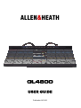
The Range
GL4800-24
24 channel console
GL4800-32
32 channel console
GL4800-40
40 channel console
GL4800-48
48 channel console
Stereo models can include mic/stereo line channels
dependant on customer specification.
4 configurations are offered:
A – All mono channels (2 stereo returns are available
above the masters)
B – 4 full stereo channels to right of masters
C – 4 full stereo channels to extreme right
D – 8 full stereos to right of masters
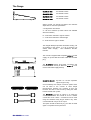
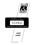
The Integral Meterpod provides illuminated moving coil
VU metering of the groups, L, R, M (or monitors, LR
sidefill, listen wedge).
Also additional PFL/AFL
indicator.
The console is supplied with a separate RPS11 power
supply, DC power cable and mains cable with moulded
plug.
The GL4800 features dual power connectors and
built-in combiner circuitry to allow two RPS11s to be
used for redundant supply backup.
GL4800-SLV2
(option)
INPUT A
SYS-LINK V2
INPUT B
Sys-Link V2 console expander
option kit (input only)
Circuit assembly and multi-pin connector system which
can be fitted to the console to allow simple
interconnection between two consoles so that one
becomes the slave of the second by linking the audio
busses and PFL/AFL system.
The GL4800 Sys-Link V2 option is an input-only
version, which allows the console to act as a master
console but not as a slave. Connections can be made
using two standard 37way D-type cables to any other
console fitted with a Sys-Link V2 output.
This option should be fitted only by your Allen & Heath
agent or competent service personnel.
GL4800 User Guide
7
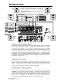
Introducing the Allen & Heath GL4800
The GL4800 offers the professional user an uncompromised feature set and
performance for the latest techniques in live sound engineering and recording.
The console is available in 24, 32, 40 and 48 channel sizes with an external 3U
rack power unit. A built-in VU Meterpod is fitted as standard. An optional SysLink V2 input expander system is available.
•
Dual function + live recording capability :
Large venue Front-of-House
Dedicated 14 mix (10 aux+4 matrix) stage monitor
Dual function combines Front-of-House and monitor
Live recording to 2-track and multitrack
•
24, 32, 40, 48 frame sizes including VU Meterpod
•
Stereo models include mic/stereo line channels depending
on customer specification
•
8 groups with inserts and trimmable balanced XLR outputs
•
L,R,M mix on balanced XLR and with inserts
•
10 Aux sends on balanced XLR and with inserts
•
4 Matrix capable of balanced XLR and inserts
•
Matrix to aux link feature for group effects and quick monitors
•
Secondary LR output capable of balanced XLR and inserts
•
Channel Direct outputs with level trim and pre/post
•
4 band full sweep channel EQ with mid Q switches
•
Stereo channel 4-point width control
•
Separate insert jacks with balanced returns
•
MIDI mute system with 128 snapshots
•
8 independent mute groups
•
Solo-In-Place feature
•
Full metering - channel, mix buss and outputs.
•
Monitor with stereo PFL, local output, 2 phones ...
•
Simultaneous stereo and mono PFL metering
•
Output meter selector switches for main or aux
•
Talkback to L-R, M, groups, matrix, and to each aux
•
2-track replay to L-R and monitor
The console is constructed using extruded aluminium beams, steel panels and
3mm thick metal side plates to ensure rigidity and mechanical reliability on the
road, as well as easy flightcasing. Individual circuit assemblies are accessible by
removal of the steel base. A durable but soft front armrest is provided for
comfort. Front, top and rear write-on strips are provided for channel marking.
High quality proven reliable parts are used throughout. High performance opamp and discrete circuits are used to ensure low noise and sonic purity.
The GL4800 reflects our commitment to providing the best audio mixing
solutions and customer support.
8
GL4800 User Guide
Here are just a few key points we considered when specifying the GL4800:
Affordability We understand your need to work within a realistic budget and know you
want to get the very best return for your investment. We know too that even the lowest
budget shows put the same tough demands on the operator who wants the reassurance of
continued reliability and intuitive control, the satisfaction of achieving that special sound,
and the functionality to deal with the trickiest situations. We have avoided the temptation of
designing in costly plastic trims and needless external add-ons for styling only. Instead we
have invested every penny of our budget into parts that make a real difference in improving
performance, durability and flexibility of use, whether the comfortable soft feel armrest, the
practically shaped space saving steel chassis, the exceptional feature set, or the ‘under the
bonnet’ engineering such as the solid grounding, individual cards, circuit enhancements
and more. The result is a no-nonsense, durable mixing tool right for its application… a
sensible investment.
Reliability Without doubt, the most important quality for any equipment intended for the
professional application. The GL4800 uses the well proven and long term serviceable
Allen & Heath method of individual channel card construction with every potentiometer
nutted to the front panel, a solid steel chassis with rigid beam front extrusion, 100mm
premium grade dual rail faders, metal bodied jacks and gold-plated Neutrik XLRs, and
sealed Alps pots and switches to ensure you can mix with confidence show after show.
The well proven RPS11 power supply has plenty of overhead and, for peace of mind, the
console includes a second DC input socket for plugging in a second supply for backup.
Performance The GL4800 benefits from our latest circuit developments which have
improved the sound and responsiveness of the signal path and EQ, and achieved
astonishingly low residual noise from the mix head amp and output stages, crucial when
mixing into modern high powered speaker systems. The mic preamp maintains ultra low
distortion and can accept as much as+34dBu to deal with the hottest signal you are ever
likely to plug in. The XLR outputs provide proper differential drive up to a massive +27dBu
to work with the longest and most hostile cable environments. Extensive listening
evaluation, together with solid engineering practice, have ensured the console achieves
accurate sound reproduction under all conditions.
Capability We know a thing or two about ‘Dual Functionality’ having pioneered this
innovative feature back in the early 90’s. The GL4800 takes this an important stage
further. Tamperproof recessed switches configure the console safely for optimum FOH or
stage monitor operation, or for mixing monitors from FOH. In MONITOR mode the ‘M’ fader
becomes the engineer’s monitor wedge control, you get all 10 aux masters available on
faders with mutes, inserts, meters and electronically balanced XLR drive, and you still get
the 4 subgroups to LR, and the groups/LR feeding the matrix. The matrix provides further
mixes ideal for in-ear monitoring, or can even be linked to the auxes to create mixes from all
channels, groups, LR and M. This console can feed up to 14 independent mixes, for
example 10 wedges and 4 mono or 2 stereo IEM. We have also considered the
RECORDING application with direct outputs on all mono channels, 4 groups, matrix and not
least the studio quality analogue mic preamps and EQ. Whatever your application you get
full control with nothing wasted.
Attention to detail In true Allen & Heath form, every detail has been meticulously
thought through. Take for example, the compact, no frills chassis that gives you a seat
saving, flight case convenient footprint, the provision of individual channel rather than
restrictive global pre/post aux switching, comprehensive talkback, full channel, mix bus and
main output metering, the multi-functional stereo strips with patchable mic pre’s and
assignable stereo inputs, the host of internal jumper options, Sys-Link V2 console input
expansion… and much more. We hope you enjoy being as creative using the GL4800
as our team enjoyed creating it.
Carey Davies, Head of Design, and sound guy too…
GL4800 User Guide
9
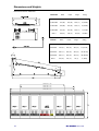
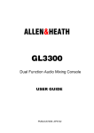
Dimensions and Weights
UNPACKED
Width
Depth
Height
Wt(kg)
GL4800-824
1166 (46”)
748 (29”)
285 (11”)
47(104lbs)
GL4800-832
1421(56”)
748 (29”)
285 (11”)
57(126lbs)
GL4800-840
1676(66”)
748 (29”)
285 (11”)
67(148lbs)
GL4800-848
1931(76”)
748 (29”)
285 (11”)
77(170lbs)
RPS11
483(19”)
232 (9”)
135 (3U)
10(22lbs)
232
132.5 (3U)
Dimensions shown in millimetres
PACKED
Width
Depth
Height
Wt(kg)
GL4800-824
1702 (67”)
900 (35”)
390 (15”)
82 (181lbs)
GL4800-832
1702 (67”)
900 (35”)
390 (15”)
91 (201lbs)
GL4800-840
1950 (77”)
900 (35”)
390 (15”)
100 (221lbs)
GL4800-848
1950 (77”)
900 (35”)
390 (15”)
129 (284lbs)
RPS11
575 (23”)
270 (11”)
170 (7”)
11 (24lbs)
285
50
35
75
77
78
GL4800-824 = 1166
GL4800-832 = 1421
GL4800-840 = 1676
GL4800-848 = 1931
x8
10
x8
x8
x8
x8
x8
GL4800 User Guide
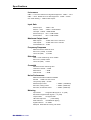
Specifications
Performance
0dBu = 0.775 Vrms Reference for high level equipment +4dBu = 1.23 V
0dBV = 1 Vrms Reference for low level equipment -10dBV = 310 Mv
0VU meter reading = +4dBu at XLR outputs
Input Gain
Mic/Line Input
+6dB to +60dB variable
Mic/Line + Pad
-14dB to +40dB variable
Line Input -14dB to +40dB variable
Stereo Line Input
off to +10dB variable
2-track Return
off to +10dB variable
Maximum Output Level
Main Outputs
+27dBu into load of >600 ohm
Jack Outputs
+21dBu into load of >2K ohm
Internal headroom +21dB
Frequency Response
Measured 20Hz to 20kHz ref 1kHz
Mic to mix (+40dB) +0/-0.5dB
Line to mix (0dB)
+0/-0.5dB
Distortion
THD + noise measured @ 1kHz +20dBu
Mic to mix (+40dB) 0.006%
Line to mix (0dB)
0.006%
Crosstalk
Referred to driven channel @ 1kHz
Channel to channel > 100dB
Mute shutoff
> 85dB
Fader shutoff
> 90dB
Noise Performance
Measured rms 22Hz to 22kHz bandwidth
Mic EIN
-128dB 150 ohm source
Line pre-amp (0dB) < -91dBu
Residual output noise
< -98dBu (-102dB S/N)
Mix noise, nothing routed
< -88dBu (-92dB S/N)
Mix noise, 24 channels routed
< -86dBu (-90dB S/N)
Metering
Input meters
4 segment LED (signal, 0, +6, peak)
Mix meters 4 segment LED (signal, 0, +6, peak)
Output meters
12 segment LED
LED meter response
peak reading
Peak indicators
on 5dB before clipping
Signal indicators
on -20dBu
Meterpod Illuminated VU moving coil meters
GL4800 User Guide
11
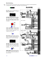
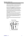
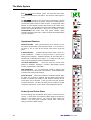
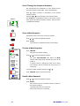
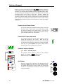
Mode Switching
Protected underpanel mode switches set the console architecture according to the required application,
for example FOH or stage monitor. Select these using a pointed object.
GL4800
DIR OUT routes the channel direct out
signal through the aux 10 pre/post
selector and level control.
AUX 1-10
GRP 1-8
LEFT
RIGHT
MONO
MTX A-D
PFL
AFL
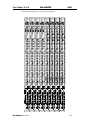
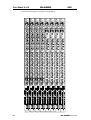
SYSTEM BLOCK DIAGRAM
PEAK
+6
0dB
SIG
4-BAND FULL SWEEP
EQUALISER
PFL
MIC/
LINE
LINE IN
-20dBu
HF
GAIN
FADER
LO-CUT
FILTER
MONO
L-R
MF1
BAL
PAN
EQ IN
MIC/LINE IN
1-2
-
2= +
3-4
5-6
MF2
OUT REV
7-8
+48V
MUTE
SEND
SAFE/PREVIEW
LF
INSERT
POST-MUTE
PRE-MUTE
0dBu
OUT REV swaps the matrix or LR2 output
jack with the related aux XLR and insert.
The control sections are not swapped.
This can provide matrix outputs on XLR
with inserts, or aux effects sends on jack
as required.
-20
-15
-10
-30
+
-
TIP = +
RING = -
INTERNAL AUX LINK OPTIONS
AUX 1
PRE-FADE
SWITCHED
POST-FADE
AUX 2
INPUT CHANNEL
AUX 3
AUX 4
POST
PRE
AUX 10/
DIR OUT LEVEL
AUX 5
PRE FADER
DIRECT OUT
-
GRP
8
-
PRE-EQ
BAL
OUTPUT
TRIM
-5
0dB
RETURN
POST-EQ
POST FADER
AUX 7
POST
PRE
0dBu
IMPEDANCE BALANCED
TIP = +
RING = -
ENABLE
AUX 6
AUX 8
AUX 10
AUX 9
Output Trim ENABLE routes the group
output signal through a pre/post fader
selector and level trim. This lets you
record the groups independent of the
subgrouping to LR and M.
POST
PRE
STEREO CHANNEL
MIC IN
MTX
MTX TO AUX Links the matrix mix into the
aux mix to include aux sends from the
groups, LR and M. Used for effects from
the groups, and for quick monitor mixes.
FADER
LO-CUT
FILTER
PAD
MONO
L-R
MF1
-20dBu
MIC IN
STEREO PFL
HF
GAIN
1
TO AUX1
PEAK
+6
0dB
SIG
4-BAND
EQUALISER
PAN
EQ IN
3-4
MF2
SUM
MUTE
SEND
SAFE/PREVIEW
LF
INSERT
POST-MUTE
PRE-MUTE
0dBu
RETURN
POST-EQ
TIP = +
RING = -
PRE-EQ
L
SUM
-
INTERNAL AUX LINK OPTIONS
R
AUX 1
PRE-FADE
SWITCHED
POST-FADE
AUX 2
AUX 3
GRP REV
STEREO LINE IN
WEDGE MODE
M MIX
AFL/PFL
MONO MODE converts the mono output
to the monitor engineers listen wedge. M
AFL is disabled. The M mix still feeds the
insert and matrix.
5-6
7-8
+48V
MIC
STEREO
GRP REV reverses the aux (small fader)
and group (main fader) control sections.
Also applies to LR. The outputs remain
unaffected. This mode is used for stage
monitoring.
1-2
-
2= +
AUX 4
GAIN
L/MONO
+
-
STEREO
LINE IN
R
TIP = +
RING = -
STEREO PFL
R
WIDTH
POST
PRE
DIR TO L-R
L
R
+
-
AUX 5
BAL
AUX 6
AUX 7
POST
PRE
AUX 8
AUX 10
AUX 9
POST
PRE
ENABLE
TALKBACK
TB LEV
TB MIC IN
TB TO MONO
TB TO L-R
TB TO GRPS
TALK
TB TO MTX
2= +
TB ENABLED
BAL
LINK
DIM
+48V
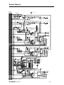
12
GL4800 User Guide
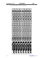
AUX 1-10
GRP 1-8
LEFT
RIGHT
MONO
MTX A-D
PFL
AFL
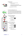
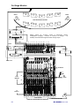
System Diagram
S
=SYSLINK INPUT OPTION
2-TRACK
RETURN
LEV
L
IN
REPLAY
TO L-R
-
OUTPUT REVERSE (LR2 / AUX 9-10)
-
R
LEV
ON
-
L(R)2 OUT
-
STEREO PFL
AFL
AUX
-
L(R)2
0dBu
IMPEDANCE BALANCED
AUX
OUTPUT REVERSE (MTX 1-4 / AUX 5-8)
MTX MIX
LEV
ON
MTX (1-4) OUT
-
TB TO AUX
ENABLE
0dBu
IMPEDANCE BALANCED
GROUP/AUX REVERSE
MTX TO
AUX (1-4)
S
-
MATRIX (1-4)
AFL
AUX MIX
PEAK
+6
0dB
SIG
INSERT
SEND
AUX (1-10)
SML
SML FADER
MAIN
+
-
RETURN
-
0dBu
BAL
AFL
METER
AUX (1-10) OUT
POST
MUTE
GRP (1-8) OUT
SAFE/PREVIEW
TRIM ON
GRP MIX
S
POST
PEAK
+6
0dB
SIG
GROUP (1-8)
+
-
RETURN
MTX 1
MTX 2
MUTE
AUX
L(R) MIX
S
AUX
L(R) / AUX9(10) REVERSE
PEAK
+6
0dB
SIG
RETURN
POST
AFL
+4dBu
BAL
MTX 1
MTX 2
MAIN
MATRIX
SENDS
MTX 3
POST
MUTE
SAFE/PREVIEW
POST-MUTE
PRE-MUTE
2=+
POST
SML
-
0dBu
BAL
L(R) OUT
-
PRE
+
-
SUBGROUPING
L-R
AUX
VU
L(R)
MAIN FADER
SEND
INSERT
MONO
PAN
PRE
-
MTX 4
PRE
SAFE/PREVIEW
POST-MUTE
PRE-MUTE
MATRIX
SENDS
MTX 3
POST
AFL
+4dBu
BAL
+
PRE
POST
-
0dBu
BAL
2=+
-
TRIM
VU
MAIN FADER
SEND
INSERT
2=+
-
MTX 4
PRE
MONO
PRE
-
R
L
R L METER
AFL MIX
L-R MIX
MONITOR
L
-
S
PFL
DC
P/AFL
DC
SUM
M
L
LOCAL
MONITOR
R OUT
PHONES
L
R
PHONES 1
PHONES 2
+
R
+
+
R
PFL
TRIM
L
LOCAL
+
PFL MIX
MONO
M
PFL
DC
AFL ACTIVE
AFL
VU
PFL ACTIVE
STEREO PFL METER
S
MONO / LISTEN WEDGE
MONO MIX
INSERT
TB DIM
PEAK
+6
0dB
SIG
SEND
+
-
RETURN
MONO
MONO OUT
FADER
-
0dBu
BAL
+4dBu
BAL
POST
MTX 2
MUTE
POST
SAFE/PREVIEW
PRE
PRE-MUTE
-
GL4800 User Guide
2=+
MTX 1
AFL
POST
MONO MODE
MTX 3
MATRIX
SENDS
MTX 4
PRE
13
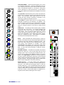
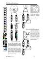
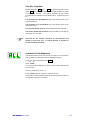
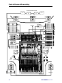
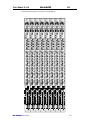
Connectors
Professional gold plated connector types are used to ensure continued reliable operation.
All the console main inputs and outputs are balanced XLRs. All 1/4" jacks are 3-pole TRS
for operation with balanced or unbalanced equipment. Inserts are provided on all channel
inputs, and on Groups, L, R, Mono and all Aux outputs. Aux can be swapped with matrix
and LR2 for XLR outputs with inserts
SEND
RESET
IN
STEREO CHANNELS
L /MONO
L /MONO
STEREO
MIDI
STEREO
LINE
IN
LINE
IN
R
THRU
INSERT
RET
RET
R
L
4
AUX8
SEND
RET
MTX
3
7
SEND
SEND
INSERT
SEND
INSERT
SEND
INSERT
SEND
INSERT
SEND
INSERT
INSERT
RET
RET
RET
RET
RET
RET
RET
GRP
GRP
GRP
GRP
GRP
GRP
GRP
GRP
MATRIX
9
SEND
SEND
CHASSIS
GROUND
A
DC POWER IN
2-TRACK
RETURN
INSERT
B
RET
L
M
8
7
6
5
4
3
2
DIRECT
OUT
GRP
1
SEND
OUT2
(MAIN)
(BACKUP)
SEND
INSERT
SEND
INSERT
SEND
INSERT
RET
LINE
IN
SEND
SEND
INSERT
INSERT
SEND
INSERT
INSERT
SEND
INSERT
SEND
INSERT
RET
RET
RET
RET
RET
RET
RET
RET
RET
RET
AUX
AUX
AUX
AUX
AUX
AUX
AUX
AUX
AUX
9
R2
MONITOR 10
MONITOR 9
L2
MTX4
MONITOR 8
GL4800
DIRECT
OUT
SEND
INSERT
AUX
10
LISTEN WEDGE
INSERT
OUT REV
SEND
INSERT
R
GL4800
SEND
INSERT
RET
MODE
RET
LINE
L2
AUX10
SEND
MIC
IN
1
5
L SEND
FOR MATRIX/LR2 ON XLR + INSERTS =
XLR
INSERT
LINE
2
6
R2
R
MIC
IN
LOCAL
INSERT
METERPOD
OUT
XLR
INSERT
R
SEND
INSERT
7
MTX3
MONITOR 7
6
MTX2
MONITOR 6
SERIAL NUMBER
5
MTX1
MONITOR 5
4
3
MONITOR 4
MONITOR 3
2
MONITOR 2
1
MONITOR 1
AUX
MIC
IN
RET
LINE
IN
LINE
IN
LINE
LINE
MIC
IN
MIC
IN
STAGE MONITOR MODE
MADE IN ENGLAND BY ALLEN & HEATH LIMITED
Direct Output
Provides a buffered signal from the channel, ideal for minimum
signal path connection to multitrack recorders or local effects
sends. Set post-fader, post-mute as standard. Can be switched
through the Aux10 send control for pre/post fader selection and
level trim with +6dB maximum boost.
3-pole 1/4" jack socket (tip = hot). Impedance balanced 50 ohm
0dBu line level for connection to balanced or unbalanced
equipment.
Insert Send
3-pole 1/4" jack socket (tip = hot).
Impedance balanced 0dBu 50ohm line level.
Insert Return
L /MONO
LINE
IN
Used to return the processed signal from external equipment into
the channel audio signal path pre-EQ.
3-pole 1/4" jack socket (tip = hot). Balanced >10kohm 0dBu line
level. (Stereo channel returns are unbalanced).
R
Mic/Line Input
3-pin female XLR (pin 2 = hot). Electronically balanced.
SEND
XLR
INSERT
RET
74dB gain range. Mic impedance >2kohm, line >10kohm
Can be used for XLR line input when the LINE IN jack is left
unplugged.
Mono Channel Line Input
LINE
MIC
IN
3-pole 1/4" jack socket (tip = hot). Electronically balanced
>10kohm.
Stereo Channel Line Input
3-pole 1/4" jack socket (tip = hot). Electronically balanced
>10kohm. Plug into the Left input only for a mono line source.
14
SEND
INSERT
RET
Used to send the channel signal to external effects and signal
processing equipment, post-pre-amp and pre-EQ.
LINE
DIRECT
OUT
GL4800 User Guide
Sys-Link V2 Expander Option
Available as a kit to be fitted to the console to expand the busses. Uses 2 37-pin
D-type connectors (input A and B). Operates at -2dBu line level. Input option
available only. Refer to your Allen & Heath agent for further details.
Group/Aux/L/R/M Insert Send
Used to send the output signal to external effects and signal processing
equipment such as graphic equalisers, delays and compressors, post-mix amp
and pre-fader.
SEND
INSERT
3-pole 1/4" jack socket (tip = hot).
RET
GRP
1
GRP
Impedance balanced -2dBu 50ohm line level.
Group/Aux/L/R/M Insert Return
Used to return the processed signal from external equipment into the output
audio signal path pre-fader and mix meter.
SEND
INSERT
3-pole 1/4" jack socket (tip = hot). Balanced >10kohm -2dBu line level.
RET
AUX
1
AUX
Group/Aux/L/R/M Main Output
3-pin male XLR (pin 2 = hot). Electronically balanced 75ohm. +4dBu line level,
+27dBu maximum into 600 ohm load.
MONITOR 1
Capable of driving long cable runs without loss or interference.
SEND
Mode Switching
SEND
INSERT
INSERT
RET
RET
R
L
Set the underpanel mode switches for the intended console operation. Some of
these affect the way the connectors work. For full details please refer to the
BLOCK DIAGRAM.
OUT REV underpanel mode switch - The Aux XLRs and inserts can swap
SEND
INSERT
RET
with the Matrix and LR2 output jacks for aux (effects) sends on jacks if required.
This also provides matrix and LR2 outputs on XLRs with inserts for driving
speaker systems.
MONO MODE underpanel mode switch - The Mono output becomes the
M
engineers listen wedge monitor feed when the console is operated in on-stage
monitor mode. However, the Mono insert remains with the mono mix.
LISTEN WEDGE
MIX/AUX REV underpanel mode switch - Note that while the front panel
control sections are swapped when the reverse mode switches are pressed, the
signals always appear at their related connectors, ie. the connectors do not
swap.
GL4800 User Guide
15
R
MTX
METERPOD
4
3
2
7
AUX8
L
LOCAL
Recessed 16-pin dual row header for connection to the meterpod.
1
6
5
R2
Local Stereo Monitor
MATRIX
L2
AUX10
9
OUT2
MODE
FOR MATRIX/LR2 ON XLR + INSERTS =
SEND
OUT REV
SEND
INSERT
RET
AUX
10
AUX
9
R2
For connection to a stereo amplifier/speaker system for LR, AFL/PFL
monitoring local to the console.
3-pole 1/4" jack sockets (tip = hot). Impedance matched 50ohm 0dBu
nominal line level.
Headphones
INSERT
RET
Meterpod Connector
L2
Connections for 2 stereo headphones >8ohms. One connector is on the
front panel, the other is concealed under the armrest.
3-pole 1/4" jack sockets (tip = left, ring = right).
MONITOR 10
MONITOR 9
Matrix Output
3-pole 1/4" jack socket (tip = hot). Impedance balanced 50ohm 0dBu
nominal line level.
Can swap with the aux output XLRs and inserts to drive long cable runs
without loss or interference, and to insert external signal processing devices
such as graphic equalisers and delays.
LR2 Output
Secondary LR output for 2-track recording, broadcast or additional speaker
and zone feeds.
3-pole 1/4" jack socket (tip = hot). Impedance balanced 50ohm 0dBu
nominal line level.
L
Can swap with the aux output XLRs and inserts to drive long cable runs
without loss or interference, and to insert external signal processing devices
such as graphic equalisers and delays.
R
2-Track Return Input
2-TRACK
RETURN
For connection to 2-track playback equipment such as cassette, DAT or CD
players.
RESET
3-pole 1/4" jack sockets (tip = signal). Unbalanced 50ohm. +10dB
maximum gain allows connection to low and high level equipment.
IN
MIDI
THRU
MIDI Interface
Standard 5-pin 180' connectors for opto-isolated connection to other MIDI
equipment. A mute processor reset switch is provided.
OUT
CHASSIS
GROUND
A
DC POWER IN
(MAIN)
INSERT
B
(BACKUP)
16
Console DC Power Input
The console connects to a separate power supply unit via a 10-pin circular
connector cable. Connect only the Allen & Heath power unit supplied with
the console. The standard power supply is the RPS11. Plug in a second
RPS11 if a redundant backup is required.
A chassis ground terminal post is provided. This connects to mains earth
through the power cable.
GL4800 User Guide
Earthing
The connection to earth (ground) in an audio system is important for two reasons:
1. SAFETY - To protect the operator from high voltage shock associated with the AC
mains supply feeding the system,
and
2. AUDIO PERFORMANCE QUALITY - To minimise the effect of earth (ground) loops
which result in audible hum and buzz, and to shield the audio signals from external
interference.
For safety it is important that all equipment earths are connected to mains earth so that
exposed metal parts are prevented from carrying high voltage which can injure or even kill
the operator. A solid, low impedance earth system is necessary to ensure that earths at
different points in the system are kept at the same potential. A typical sound system
includes amplifiers, signal processing equipment, microphones, musical instruments and
much more in addition to the console, all of which require earth connection for safety and
correct audio operation.
Often this equipment is spread across the venue and
interconnected by hundreds of metres of power and audio cables. It is recommended that
the sound engineer check the continuity of the safety earth from all points in the system
including microphone bodies, guitar strings, muticore cases, equipment panels ...
The same earth is also used to shield audio cables from external interference such as the
hum fields associated with power transformers, lighting dimmer buzz, and computer
radiation. Earth is also used for the signal 'return' when connecting to unbalanced
equipment. Problems arise when the signal sees more than one path to mains earth. An
'earth loop' (ground loop) results causing current to flow between the different earth paths.
A larger potential difference between these paths results in more current flow and so more
audible noise. This condition is usually detected as a low frequency hum or buzz at mains
frequency or its harmonics.
To ensure operator safety and trouble-free audio performance from your system we
recommend the following :
Do not remove the earth connection from the power unit mains plug. The console
chassis is connected to mains earth through the power cable to ensure your safety. Audio
0V is connected to the console chassis internally. If problems are encountered with earth
loops operate the audio 'ground lift' switches on connected equipment accordingly, or
disconnect the cable screens at one end, usually at the destination. It is useful to carry
ground lift cable adaptors such as short XLR male to female leads with pin1 disconnected.
Use a separate 'clean' mains outlet for the audio equipment to prevent interference
from other equipment such as lighting, stage machinery and vending machines. Ensure a
good central 'star point' earth connection.
Avoid running audio cables next to mains, computer or lighting cables, or near
thyristor dimmer and power supply units. If unavoidable, cross these at right angles.
Use low impedance sources such as 200 ohm or less microphones to reduce
susceptability to interference. The console outputs are designed to operate at very low
impedance to minimise interference problems.
Use balanced connections where possible as these provide further immunity by
cancelling out interference that may be picked up on long cable runs. To connect an
unbalanced source to a balanced console input, link the cold input (XLR pin3 or jack ring)
to 0V earth (XLR pin1 or jack sleeve) at the console. To connect a balanced console output
to an unbalanced destination, link the cold output to 0V earth at the console.
Use professional quality cables and connectors and check for correct wiring and
reliable solder joints.
If you are not sure ... Have your system checked by a competent engineer, or contact
your local Allen & Heath agent for advice.
GL4800 User Guide
17
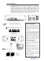
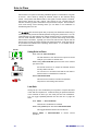
Connecting Power
Connect only the Allen & Heath power unit specified for the console. The standard unit for
GL4800 is the RPS11. This is an external 3U 19" rack mounted unit that connects to
the console via the separate DC cable supplied. The RPS11 is a low noise linear design
that converts AC mains voltage to the DC voltages required to power the console. It also
provides +48V phantom power for use with high quality powered microphones. The
presence of AC mains voltage is shown on the power unit front panel neon indicator. The
presence of the DC voltages is shown on the console power indicator LEDs. A second
backup RPS11 may be connected to the console via the backup DC power connector
(located adjacent to the main DC power connector at the rear of the console).
DO NOT OBSTRUCT VENTILATION OPENINGS.
ALLOW ADEQUATE VENTILATION AROUND THE UNIT.
SEE INSTALLATION INSTRUCTIONS BEFORE CONNECTING TO THE SUPPLY.
POWER
DC FUSES
T 10A 250V 20mm
ON
V+
CAUTION: FOR CONTINUED PROTECTION AGAINST RISK OF FIRE
REPLACE FUSE WITH SAME TYPE AND RATING.
ATTENTION: REMPLACER LE FUSIBLE AVEC UN DES MEMES
CARACTERISTIQUES.
OFF
V-
DO NOT OBSTRUCT VENTILATION OPENINGS.
ALLOW ADEQUATE VENTILATION AROUND THE UNIT.
SAFETY WARNINGS !
Ensure that the warnings printed on the
power unit (shown here) are followed.
WARNING: THIS APPARATUS MUST BE EARTHED.
WARNING: TO REDUCE THE RISK OF ELECTRIC SHOCK, DO NOT EXPOSE THIS APPARATUS TO RAIN OR MOISTURE
CAUTION
It is normal for the power unit to dissipate
heat. Do not cover the unit or position it
on soft furnishings during operation. Do
not position other equipment known to
generate significant amounts of heat
below the unit. It is recommended that
rack units containing high power
amplifiers and other heat dissipating
equipment are fitted with cooling fans.
AVIS: RISQUE DE CHOC ELECTRIQUE - NE PAS OUVRIR.
NO USER SERVICEABLE PARTS INSIDE
CAUTION: FOR CONTINUED PROTECTION AGAINST RISK OF FIRE REPLACE FUSE
WITH SAME TYPE AND RATING.
ATTENTION: REMPLACER LE FUSIBLE AVEC UN DES MEMES CARACTERISTIQUES.
WARNING: THIS APPARATUS MUST BE EARTHED.
WARNING: TO REDUCE THE RISK OF ELECTRIC SHOCK, DO NOT EXPOSE THIS APPARATUS TO RAIN OR MOISTURE
AVIS: RISQUE DE CHOC ELECTRIQUE - NE PAS OUVRIR.
DC OUT
Always switch the power unit off before
connecting or disconnecting the console
power cable.
NO USER SERVICEABLE PARTS INSIDE
CAUTION: FOR CONTINUED PROTECTION AGAINST RISK OF FIRE REPLACE FUSE
WITH SAME TYPE AND RATING.
ATTENTION: REMPLACER LE FUSIBLE AVEC UN DES MEMES CARACTERISTIQUES.
AC MAINS IN ~
Made in the UK by
RPS11
CONSOLE POWER SUPPLY
FUSE TYPE
T 3.15A 20mm
T 5.0A 20mm
SERIAL No:
AC SUPPLY
220 - 240V~
100 - 120V~
47-63Hz
320VA MAX
300W MAX
Before Switching On !
Check that the voltage indicated on the
fuseholder is correct for the mains voltage
in your area.
AC MAINS IN ~
Check that the mains IEC connector is
fully inserted into the inlet socket.
FUSE TYPE
T 3.15A 20mm
T 5.0A 20mm
A
DC POWER IN
B
Console
DC Power
Connectors
(MAIN)
18
(BACKUP)
AC SUPPLY
220 - 240V~
100 - 120V~
47-63Hz
320VA MAX
300W MAX
Check that the DC power cable is
correctly fitted to both the power unit and
the console. The locking ring should be
screwed in place.
It is recommended that audio power
amplifiers are switched on last and
switched off first to prevent possible
damage to loudspeakers.
Check the system for safety earthing.
GL4800 User Guide
Matching the Signal Levels
For best performance it is important that the connected source signals are
matched to the "normal operating level" of the console. Similarly the console
outputs should be correctly matched to the operating levels of the connected
amplifiers and destination equipment. If too high the signal peaks will be
clipped resulting in a harsh distorted sound, and if too low the signal-to-noise
ratio is reduced resulting in excessive background hiss and noise.
For best results operate the console with the meters averaging around '0'
letting the louder passages peak into the 'yellow'. Reduce the gain if the red
peak indicators flash. The GL4800 produces a standard XLR output level
of +4dBu for a meter reading of 0VU. It is advisable to adjust the power
amplifier input gain or fit an attenuator pad if normal console operation results
in an output level too high for the connected amplifier. Normal operation
should result in fader levels around the '0' mark. Note that when reversed
with the auxes the matrix and LR2 output level trims can be used to match the
console to the amplifiers independent of the mix levels. Similarly the group
output trims can be switched in to match levels.
The GL4800 has an advanced PFL (pre-fade listen) / AFL (after-fader
listen) and channel metering system to let you listen to and check the level of
signals at different points in the signal path without affecting the main
outputs. Use the channel PFL switches to set up the input GAIN controls to
read an average '0'. Signal activity is always shown on the channel meters
regardless of fader position. The green 'SIG' LED lights at -20dBu to indicate
signal presence, the green '0' LED indicates normal level, yellow '+6'
indicates normal peaks, and the red 'PEAK' LED warns of potential overload
5dB before clipping.
The mix meters above each output fader monitors the pre-fade mix level. You
can run the mix 'hot' but reduce the channel fader levels if the red 'PEAK'
LEDs flash.
Dynamic Range
GL4800 User Guide
19
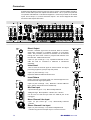
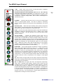
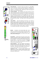
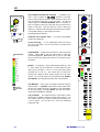
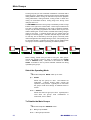
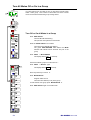
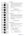
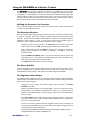
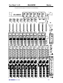
The MONO Input Channel
+48V - Feeds +48V to pins 2 and 3 of the input XLR for condenser
microphones which require phantom power.
+48V
POLARITY
MIC
LINE
0dB
20
-10
10
40
LINE MIC
50
6
-14
PAD
30 10
30
HPF
100
200
20
OFF
400Hz
10k
2kHz
20kHz
-15
HF
+15
Q
3k
1k
5k
7k
700
500Hz
15k
-15
+15
HM
Q
180Hz
60
300
45
35Hz
-15
50
20Hz
-15
450
1kHz
LM
+15
100Hz
150
200Hz
+15
EQ IN
20
POLARITY - Reverses XLR input pins 2 and 3 to correct for reverse wired
cables or reversed phase signals. Can also be effective in minimising
acoustic feedback between the microphone and loudspeakers in live sound
mixing.
MIC/LINE (PAD) - Selects line input sensitivity when pressed, microphone
when released. Note that with the line jack unplugged the switch acts as a
20dB pad for high output microphones or line input on XLR.
7kHz
3k
GAIN
60 40dB
50Hz
Plug the microphone in before switching +48V on or off. Use +48V only
with balanced microphones and cables. No damage will occur when +48V
is switched to balanced non-phantom powered transformer coupled dynamic
microphones. However, always switch +48V off when connecting line or
unbalanced sources.
LF
GAIN - Use this control with the MIC/LINE switch to adjust the channel input
sensitivity to match the connected source (-60 to +14dBu) to the console
operating level (0dBu). The gain should be set so that the channel meter
reads an average '0'.
LO-CUT FILTER
Reduces low frequency source noise such as
microphone proximity popping, stage noise and transport rumble. Can be
used to clean up sounds that do not have much bass content such as vocals
(around 150Hz), separate out the top end of a drum kit (400Hz), reduce the
handling noise of acoustic instruments, and so on. Select the required cut off
frequency by sweeping from fully anticlockwise (filter off) to the maximum
400Hz. Setting the cutoff to 50Hz will have little effect on most program
material but will protect the low frequency speaker drivers. The response
drops by 12dB per octave below the cut off frequency.
EQUALISER - This provides separate, simultaneous control of 4 frequency
bands. Each band may be boosted or cut by up to +/- 15dB centred on the
selected frequency which may be swept across a wide range. Use the
equaliser to correct for tonal deficiencies in the source such as acoustic
resonances or poor microphone response (corrective EQ), or to change the
tonal balance, for example to brighten up a guitar so it cuts through the mix
(effective EQ). You may need to adjust the input GAIN control when using
excessive amounts of EQ to compensate for the change in overall signal
level.
HF and LF affect the high (treble) and low (bass) frequencies respectively.
These have a shelving response which means that all frequencies beyond the
selected frequency are affected.
MF1 and MF2 affect the upper and lower mid frequencies respectively.
These have a peak/dip (bell shaped) response which means that the
maximum boost or cut occurs at the selected (center) frequency. The MF1
and MF2 bands overlap for additional cut or boost when required or to
provide a tailored frequency response to suit any application. The sharpness
of the curve is selected using the Q switch to a Q of either 1 (wide band) or
2.4 (narrow band). Use wide band when you want to add presence or
warmth to the sound. Use narrow band to control problem frequencies for
example when notching out acoustic resonances.
GL4800 User Guide
AUX
0dB
1
+6
AUX
2
0dB
+6
AUX
0dB
3
+6
AUX
0dB
4
+6
POST
PRE
AUX
0dB
5
+6
AUX
6
0dB
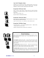
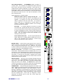
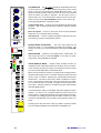
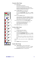
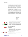
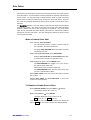
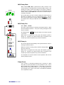
AUXILIARY SENDS - Route the channel signal to one or more
of 10 auxiliary send busses. These are independent from the
main outputs and may be used for effects sends and monitor
mixes. The sends are grouped 1-4, 5-8, and 9-10. Each group
may be selected pre or post channel fader. A further 6dB of
boost above 0dB normal channel level is available on the send
control.
Use post-fade for effects sends such as reverb. The amount of
signal sent to the effects unit follows the fader level and mute
switch. The processed ("wet") signal returned to the mix
through the return channel is therefore in proportion to the
direct ("dry") signal from the fader to the mix.
Use pre-fade for monitor sends such as to on-stage monitor,
backstage, orchestra pit, and musicians cue speakers. The
amount of signal in the monitor mix is independent of the fader
level. Pre-fade sends are post-EQ, post-mute as standard.
(may be configured pre-EQ or pre-mute by setting internal
links).
DIRECT OUT - The 0dBu post-fade channel signal is available
at the DIR OUT jack socket. For pre/post selection and
independent level control select the underpanel DIR OUT
mode switch. The 9-10 pre/post switch and aux 10 send
control now affect the direct out signal. Select POST for an
effects send dedicated to that channel (local effect) without
tying up a complete aux buss. Select PRE for a multitrack
recording send with independent level control.
=
PAN
ODD
+6
AUX
0dB
7
+6
AUX
0dB
8
+6
POST
PRE
AUX
0dB
9
+6
AUX
0dB
+6
POST
PRE
10
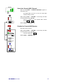
MUTE - When illuminated the channel signal is turned off
(muted). This affects both pre and post fade signals unless the
pre-fade aux has been internally configured pre-mute. The
silent action mute element can be controlled by the switch,
mute groups, mute snapshots or via MIDI.
The green
SAFE/PREVIEW LED indicates if the channel has been made
'safe' so that it is not affected by the mute groups, snapshots or
MIDI. It is also used when previewing or editing the groups
and snapshots.
ROUTING and PAN - The PAN control positions the channel
signal in the stereo mix. The post-pan signal may be routed
directly to the L-R mix or to the groups in odd/even pairs. The
groups may be used to feed additional outputs or recording
tracks, or for subgrouping combinations of channel signals to
the mix so that the overall level of the group can be controlled
without affecting the balance between the signals, for example
the drum kit mics. The pre-pan signal may be routed to the
MONO output independent of the stereo positioning.
METER and PFL - The peak reading meter displays the
channel signal pre-fader. Use this to monitor signal presence
and level. The signal should average around '0' with the
loudest peaking at '6'. If the red PEAK light flashes the signal
level is too high (5dB below clipping) and should be reduced
using the GAIN control to prevent possible overload distortion.
Press PFL to listen to the pre-fade signal on headphones or
engineers monitor without affecting the main outputs.
GL4800 User Guide
21
L
R
EVEN
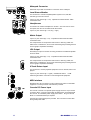
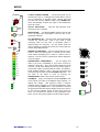
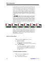
The STEREO Input Channel
+48V
POLARITY
MIC
LINE
0dB
20
PAD
30 10
-10
10
XLR
GAIN
40
50
LINE MIC
6
-14
60 40dB
50Hz
30
HPF
100
200
20
OFF
400Hz
POLARITY
(R)
STEREO
WIDTH
MONO
REVERSE
-5
WIDE
0dB
STEREO
GAIN
-10
+5
-20
-30
+10dB
The stereo channel has two independent input sections: XLR IN for mono
microphone or line input, and STEREO LINE IN on jacks for sources such as
stereo keyboards, voice modules and effects returns. When using the
channel as a mono XLR mic/line input the stereo line input can be
independently routed to L-R for a stereo effects return or additional line input.
The XLR inputs on adjacent channels can be patched into a stereo line when
using stereo or paired microphones.
XLR MIC/LINE INPUT - This section is the same as the mono channel input
except that it has only the XLR input for both mic or line. It uses the same
wide ranging balanced pre-amp stage and includes the swept lo-cut filter and
insert. Refer to the MONO INPUT section for a detailed description of these
controls.
STEREO LINE INPUT - The left/mono and right inputs feed a balanced preamp stage with GAIN variable from fully off to +10dB boost. Press
POLARITY (R) to reverse the phase of the right input signal to correct phase
differences between the inputs. The WIDTH control is normally set to the
centre detented position for normal stereo. Turn anticlockwise to narrow the
stereo image until it becomes mono. Continue anticlockwise to open up the
stereo image but with left and right reversed. Turning clockwise from centre
accentuates the stereo effect by producing a phase enhanced "wide" image.
Press PFL to listen to the stereo signal on headphones or local monitor
without affecting the main outputs.
DIRECT TO L-R routes the stereo line signal to L-R independent of the main
stereo channel which you may be using as a mic/line XLR input. The GAIN
control adjusts the level to L-R. PFL lets you check the post-gain, post-width
stereo signal independent of the main channel PFL.
DIRECT
TO
L-R
STEREO
PFL
XLR
STEREO
HF
XLR/STEREO selects the input source to the main stereo channel. When
pressed the stereo line input is selected, when released the XLR mic/line
input is selected.
12kHz
-15
+15
HM
2.5kHz
-15
+15
LM
250Hz
-15
+15
LF
70Hz
-15
+15
EQ IN
22
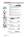
EQUALISER - This provides separate, simultaneous stereo control of 4
frequency bands. Each band may be boosted or cut by up to +/- 15dB. HF
and LF have a shelving response and affect the high (treble) and low (bass)
frequencies respectively. MF1 and MF2 have a peak/dip (bell shaped)
response and affect the upper and lower mid frequencies respectively. MF1
is centred on 2.5kHz (presence) and MF2 is centred on 250Hz (warmth).
Careful use of the equaliser can go a long way to brightening up the sound of
your stereo instruments, or tuning out the noise characteristic of many lower
cost effects units.
AUXILIARY SENDS - 10 aux sends are provided. These work in the same
way as the mono channel. Note that the left and right signals are combined
as mono aux sends. No direct output facility is available.
ROUTING, PAN, METER and PFL - These are the same as on the mono
channel. When a stereo input is selected PAN acts as a balance control to
adjust the level of the left and right signals relative to each other. The meter
indicates the pre-fade left and right signals combined. PFL operates in stereo
so that you can hear the image of the stereo source and check the relative
levels on the L and R meters.
GL4800 User Guide
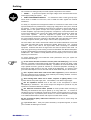
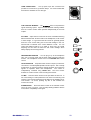
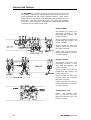
M-S Stereo Microphones
L
Stereo Microhones
R
MIDDLE
This example shows two
cardiod
microphones
arranged
as
an
X-Y
coincident
pair.
This
minimises
the
phase
differences which can cause
problems when the mics are
arranged as a spaced pair.
AUX
0dB
1
+6
AUX
0dB
L
SIDE
R
SIDE
2
CARDIOD
+6
AUX
FIGURE-OF-8
3
0dB
L
+6
AUX
0dB
C
4
+6
POST
PRE
8
LINE
LINE
MIC
IN
MIC
IN
R
LINE
LINE
MIC
IN
MIC
IN
+48V
AUX
+48V
5
0dB
+6
POLARITY
POLARITY
MIC
LINE
MIC
LINE
+48V
POLARITY
POLARITY
MIC
LINE
MIC
LINE
AUX
6
0dB
PAD
PAD
XLR
GAIN
XLR
GAIN
HPF
HPF
+48V
PAD
PAD
XLR
GAIN
XLR
GAIN
HPF
HPF
SEND
SEND
XLR
INSERT
+6
AUX
0dB
7
XLR
INSERT
RET
SEND
RET
SEND
XLR
INSERT
XLR
INSERT
RET
RET
L /MONO
+6
STEREO
LINE
IN
AUX
0dB
8
L /MONO
L /MONO
STEREO
R
STEREO
LINE
IN
LINE
IN
R
+6
POLARITY
(R)
R
WIDTH
POST
PRE
POLARITY
(R)
WIDTH
AUX
0dB
9
STEREO
GAIN
STEREO
POLARITY
(R)
STEREO
GAIN
WIDTH
REVERSE
STEREO
DIRECT
TO
STEREO
GAIN
L-R
STEREO
+6
PFL
AUX
0dB
10
+6
DIRECT
TO
DIRECT
TO
STEREO
STEREO
L-R
L-R
XLR
STEREO
PFL
PFL
XLR
STEREO
XLR
STEREO
PAN
PAN
Above and Below Microphones
POST
PRE
=
BAL
Here, two microphones are
used on the snare drum to
get the best balance between
stick
sound
and
skin
resonance on top, and snare
sound below. Reversing the
phase of the lower mic can
compensate for the opposite
skin resonance between the
mics. Signal processing such
as noise gates can be
patched in as shown.
BAL
PAN
BAL
ODD
L
R
The mic input stages are
patched into a stereo line
input for single fader control.
The second stereo channel
may be used for an
independent line input.
EVEN
ABOVE
SNARE
BELOW
A
MONO
SIDE
LINE
MIC
IN
MIC
IN
L = M+S
R = M-S
The M-S stereo configuration is often
preferred when simultaneous mono feeds
are derived from the stereo signal. Here,
a cardiod and a figure-of-8 mic are
positioned on the same stand.
The
cardiod picks up the "middle" (mono)
signal, and the figure-of-8 the "side"
(stereo content). Stereo is extracted from
the mic signals by producing sum and
difference channels. When combined the
stereo content is cancelled out leaving
true mono. Balance the two faders to
achieve the desired image.
B
LINE
+48V
+48V
POLARITY
POLARITY
MIC
LINE
MIC
LINE
PAD
PAD
XLR
GAIN
XLR
GAIN
HPF
HPF
SEND
SEND
XLR
INSERT
XLR
INSERT
RET
RET
SIGNAL PROCESSING
L /MONO
STEREO
LINE
IN
R
POLARITY
(R)
WIDTH
MONO
STEREO
GAIN
DIRECT
TO
L-R
STEREO
PFL
XLR
STEREO
GL4800 User Guide
23
GROUP
-20
-15
-10
-30
LEV
-5
0dB
ON
AFL
OUT REV
POST
PRE
-20
-15
OUTPUT
TRIM
-10
-30
-5
0dB
GRP
8
ENABLE
8
+16
MATRIX MASTER - Controls the output of the matrix mix. Adjust LEV to
trim the output level to match the connected equipment. ON switches the
output on or off, ideal for checking the effect of individual or combinations of
speakers in a multispeaker system. AFL lets you monitor the signal post
level trim, post insert, but pre ON switch.
OUTPUT REVERSE - This underpanel mode switch reverses the matrix
output jack with the related aux output XLR and switches the aux insert out of
the aux signal path and into the matrix path. This gives the matrix a balanced
XLR for driving the long cable runs to the amplifier racks, and an insert for
plugging in processing devices such as graphic EQ and delay units. You
could also use this to provide aux outputs on jack, often more convenient
when connecting to some of the lower cost effects devices. Note that only
the connectors are reversed. The matrix and aux control sections are not
affected.
TRIM ENABLE - With this underpanel mode switch in the normal up
position the group output is fed post fader to the output XLR. Press the
switch to insert a level trim control in the group output signal path. This does
not affect the level of the subgrouping to LR and M. You can also select
whether the group output is sourced pre or post the group fader. This facility
is most useful when using the group outputs for recording. The recording
can be adjusted independent of the subgrouping and faders.
+9
+6
+3
0
-3
-6
-9
-12
-15
MUTE
METER - 12 segment, 3 colour peak reading meter. Each
meter can be switched to monitor either the main fader signal
(normally group) or the small fader signal (normally aux). The
switch does not affect the optional VU meterpod which always
follows the main fader signals.
-20
-30
FOLLOW
SML FADER
SAFE/PREVIEW
AFL
PK!
10
+6
AUX MASTER - Provides fader control of the aux send output.
Includes a pre fader aux meter to display signal activity and
warn of potential mix overload. AFL monitors the post insert,
post fader signal. You can listen to the effect of graphic EQ
typically inserted in a stage monitor signal path. The MUTE
switch is part of the console mute grouping and automation
system and includes preview and safe.
GROUP REVERSE - Press this underpanel mode switch to
reverse the aux and group control sections. This configures
the group for stage monitor operation giving you auxes on the
main faders. The groups are still available on the small faders.
The aux and group output connectors are not affected.
TALKBACK TO AUX - This switch enables talkback to the
related aux mix. When selected, pressing the large TALK
switch routes talkback to the aux. When not selected, pressing
TALK does not affect the aux.
5
0
SIG
0
5
10
20
30
MTX
1
TO AUX1
GRP REV
TB TO
AUX1
24
GL4800 User Guide
THE CONSOLE MATRIX - The GL4800 includes a versatile 11 x
4 output matrix. This comprises four independent outputs each with
level control, ON switch and AFL monitoring. Each matrix mix is
created from the desired combination of group (x8), L (left), R (right)
and M (mono) signals. The level of each source is adjusted using the
matrix SEND controls above the main faders in much the same way as
the channel aux sends are used. The output is selectable to a TRS
jack or XLR with insert.
MTX
0dB
+6
MTX
0dB
Typical applications of a matrix include:
MTX
0dB
3
+6
MTX
0dB
+6
4
GRP
8
POST
PRE
=
PAN
L
R
Video and Broadcast feeds - The mix may be balanced and
stereo image set as required without affecting the PA mix.
Often a mono broadcast feed is asked for. Set this up by
mixing in equal amounts of the L and R mix.
MATRIX SENDS - These route the group signal to one or more of 4
matrix mix busses. The source may be selected pre or post group
fader. The level may be adjusted from off to +6dB boost. The normal
'0' level is marked on the control dial. The matrix source is always fed
from the groups even if GRP REVERSE is selected.
MATRIX TO AUX LINK - Aux masters 1 to 4 include this underpanel
mode switch. When pressed this links the related matrix mix (1 to 4)
to the aux mix. This unique feature lets you extend the aux mix across
the master section so that monitors and effects can be created from
the groups, L, R and M, pre or post fader. Similarly, the aux output
may be used as a matrix created from the master section and with
additional feeds from the channels.
GROUP MASTER - The group mix is normally controlled using the
100mm main fader. If GRP REVERSE is selected this section controls
the aux mix. A pre fader group meter is included to display signal
activity and warn of mix overload. The MUTE switch is part of the
console mute grouping and automation system and includes preview
and safe. AFL monitors the signal post insert and post fader.
SUBGROUPING - The post fader group signal can be routed to the
main L-R and/or M outputs by pressing the switches to the left of the
fader. PAN adjusts the position of the signal between L and R.
Routing a combination of channel signals to a group and then routing
the group to the main mix lets you control the level of the combined
signals with a single fader. Routing and panning to a pair of groups
and then panning them L and R lets you subgroup in stereo.
Subgroups are typically used for drum kits, vocals, stage mics,
backline instruments etc.
GL4800 User Guide
2
+6
Additional speaker feeds for zoning and delay fills - The
mix may not be exactly the same as that feeding the LR
speakers. For example, the vocals may be boosted to aid
clarity for listeners at the rear of the venue. It is common to
insert a delay unit to compensate for acoustic delay if the
speaker is positioned a significant distance from the stage.
Some EQ may also be required.
Recording - It is seldom adequate to record live to 2-track
from the LR mix. Typically the LR house mix is 'vocal heavy' as
much of the instrument sound is heard acoustically and the PA
is used to supplement the sound. Use two matrix outputs and
create a more balanced mix for the recording using the matrix
sends. Here, the 'backline' sound can be boosted on the
related group send controls.
1
25
LR
-15
-20
-10
-30
LEV
-5
0dB
ON
AFL
THE CONSOLE LR AND LR2 OUTPUTS - In addition to the
main L and R outputs the GL4800 includes a secondary
pair of outputs called L2 and R2. These follow the LR mix and
may be selected either pre or post LR faders. As with the
matrix outputs an OUTPUT REVERSE switch is included on
each to swap the L(R)2 jack output with aux 9(10) XLR and to
switch in the insert. Use this when you need to drive long
cable runs, interface with standard XLR multicores and cables,
or insert EQs, delays or other signal processors.
Typical applications include:
OUT REV
POST
PRE
MTX
0dB
1
+6
MTX
0dB
2
+6
MTX
0dB
3
+6
Additional stereo speaker feeds - For zoning, dual speaker
systems and delay fills.
2-track Recording - For an independent feed from the LR
mix, pre or post fader. Can also be used as a simple stereo
broadcast feed.
MTX
0dB
4
L
+6
POST
PRE
L TO M
L
+16
+9
L(R)2 MASTER - Selects and controls the L and R secondary
outputs. Adjust LEV to trim the output level to match the
connected equipment. ON switches the ou tput on or off. AFL
lets you monitor the signal post level trim, post insert but pre
ON switch.
+6
+3
0
-3
-6
-9
-12
-15
-20
METER - 12 segment, 3 colour peak reading meter for L and
R. Each meter can be switched to monitor either the main
fader signal (normally L and R) or the small fader signal
(normally aux 9 and 10). The switch does not affect the
optional VU meterpod which always follows the main fader
signals. The L and R meters can be switched using STEREO
PFL METER to be interrupted by stereo PFL when selected.
-30
FOLLOW
SML FADER
L(R) MASTER - The LR mix is normally controlled using the
100mm faders. If L(R) REV is pressed the main faders follow
the aux 9(10) signals and L(R) is available on the small faders.
As with the groups: automated MUTE, pre fade mix meters,
matrix sends and AFL are available.
L(R) TO MONO - The required amount of post fade L and R
signal may be added to the M mix using these controls. You
can create a quick mono output by mixing in equal amounts of
L and R signal. You can also use L and R as additional
subgroups to M.
26
GL4800 User Guide
0dB
MONO
2TRK RETURN
-5
LEV
-2
0dB
-10
+5
-20
+8
+10dB
-30
REPLAY
TO L-R
PFL
AFL
ACTIVE
PFL
STEREO PFL
MONO
M
+16
+9
+6
+3
0
-3
-6
-9
-12
-15
-20
-30
48V
+V
-V
2-TRACK STEREO RETURN - The incoming level can be
trimmed from OFF to +10dB gain and routed direct to the LR
mix for intermission or recording replay. Monitor the signal
post LEV trim and pre REPLAY switch using STEREO PFL
which automatically overrides the signal in the headphones
and local monitor.
AFL/PFL INDICATORS - Large red LED indicators show
when AFL or PFL is selected.
MONO METER - The MONO METER follows the post fade
mono mix signal and is interrupted to show the AFL or PFL
signal when selected.
PFL INTERRUPTS AFL - Pressing a PFL switch automatically
overrides any selected AFL. This is most useful in stage
monitoring when you may wish to continually monitor a
selected stage mix using AFL. You can quickly check the
channel signals by pressing PFL which cuts out the stage mix
monitor signal while selected.
STEREO PFL METERING - Press the switch above the mono
meter to allow any selected PFL to override the LR meters.
These meters will display PFL in stereo if a stereo source is
selected. If a mono source is selected both meters display the
mono PFL signal.
TB
MIC IN
STEREO/MONO COMPATIBILITY - You can display and
listen to the mono compatibility of your stereo sources by
selecting a stereo PFL. The L and R meters display the signal
in stereo. The M meter displays the LR sum (mono) signal. A
low M meter reading compared with LR meters can indicate a
phase problem between L and R. This can be checked and
corrected using the stereo channel POLARITY (R) switch. You
can listen to the signal in mono by pressing the
STEREO/MONO switch in the console monitor section.
TB TO
M
TB TO
L-R
TB TO
GRP
TB TO
MTX
TALKBACK - Plug in a microphone and adjust TB LEV to talk
to the outputs you select on the talkback assign switches. An
internal link assigns +48V phantom power if required.
Talkback will be activated to the selected destinations when
you press the large TALK button. If any destination is selected
the green LED in the TALK button will light, useful if you want to
be sure that the talkback system is made 'safe' during the
show. You can talk to the 10 auxes in any combination, to the
M mix, LR mix, all 8 groups together, and all 4 matrix together.
GL4800 User Guide
4
5
6
3
7
2
TB
LEV
8
1
9
0
10
TALK
27
MTX
0dB
1
+6
MTX
0dB
2
+6
MTX
0dB
3
+6
MTX
0dB
+6
POST
PRE
WEDGE MODE
M MIX
AFL/PFL
4
M
THE MONO MIX - The GL4800 includes an independent mix buss
for the M (mono) output. Each channel and group can be routed
direct to this buss by pressing the related M routing switch. The
signal is sourced pre PAN control so that the mono mix is not affected
when the stereo mix image is adjusted. The M output can be a
different mix to LR. If you want the mono output to be the sum of the L
and R mix then use the L(R) TO MONO controls to mix L and R to M.
Some typical applications of the Mono output:
Centre speaker feed - To fill out the sound between the left and right
speakers. This is usually positioned to benefit the audience nearest
the stage.
Mono PA system - Here, the L and R mix can be used as additional
subgroups or for a separate stereo recording.
Sub bass feed - To drive a speaker designed to reproduce the very
low frequency sounds in multi speaker systems.
MATRIX SENDS FROM MONO - The mono buss signal may be
mixed into matrix 1 to 4 by adjusting the matrix send controls. The
signal is sourced pre or post the M fader by selecting the POST/PRE
switch.
MONO MASTER - The M mix is controlled using a 100mm fader. As
with the groups and LR: automated MUTE, a pre fade mix meter,
matrix sends, insert and AFL are available.
STAGE MONITOR MODE - Unique to Allen & Heath consoles, an
underpanel mode switch determines how the Mono section operates.
In the normal up position it provides a conventional mono buss output
for front-of-house applications as described above.
When pressed, the Mono section is reconfigured as the stage monitor
engineers listen wedge control. The Mono output becomes silent until
an AFL or PFL is selected. Pressing PFL automatically overrides any
selected AFL. The Mono section AFL switch is disabled in monitor
mode. Pressing AFL monitors the output post insert and post fader.
You can hear the effect of any EQ or signal processing inserted into
the outputs. The listen monitor is controlled using the 100mm MONO
fader with MUTE switch.
Connect the Mono output to an amplifier driving the engineers monitor
speaker. It is best to use a speaker identical to those used for the
stage monitors, usually wedge shaped (hence the term listen 'wedge').
You would not normally plug an EQ into the listen monitor as it is best
to hear the selected listen source exactly as the performer hears it on
stage.
Pressing TALK dims the listen output by 20dB to prevent possible
acoustic feedback between the local speaker and talkback mic.
28
GL4800 User Guide
LAMP CONNECTORS - Two top panel 4-pin XLR connectors are
provided for connection to gooseneck lamps. It is recommended that
these are the standard 12V 2.5 watt type.
LAMP
THE CONSOLE MONITOR - The GL4800 offers a comprehensive
signal monitoring system. Apart from the extensive metering facilities
there is a monitor section which operates independently of the main
outputs.
PFL TRIM - Adjust the trim control for the most comfortable listening
balance between AFL and PFL levels in the headphones, local monitor
or listen wedge. It is ypical that the AFL levels are generally quieter
than PFL in live sound mixing due to the fader settings in the mix.
Normal level is indicated at the centre detented '0' mark. You can
reduce the listening level by up to 12dB, or boost it by up to 6dB.
Adjusting the trim does not affect the PFL meter readings which
always display the actual signal level.
0dB
PFL
TRIM
+6
-12
L-R MIX
STEREO
MONO
4
5
6
3
7
8
2
HEADPHONES MONITOR - You can plug in up to two headphone
sets, one on the top panel and the other safely protected under the
armrest. The headphone monitor has its own PHONES LEV volume
control.
1
9
0
4
10
5
6
3
7
1
9
0
10
1
L-R MIX - Press this switch to listen to the post fader LR main mix. In
live sound mixing it is often preferred to turn off the LR monitoring until
required. This prevents distracting audio spill from the headphones or
local monitor. Of course, pressing any AFL or PFL activates the
monitors as normal.
STEREO/MONO - Press this switch to listen to the selected monitor
source in mono (L+R sum). This can help identify problems with the
mono/stereo compatibility of the signal.
GL4800 User Guide
PHONES
LEV
8
2
LOCAL MONITOR - A separate stereo monitor output is provided for
connection to a local amplifier/speaker monitor system. This is usually
positioned on or near the console so that the engineer can monitor the
signals on speakers rather than headphones.
The volume is
independently controlled using LOCAL LEV. The local monitor
doubles as a studio monitor in the recording environment.
LOCAL
LEV
29
The Mute System
SNAPSHOT
Each GL4800 input channel, group, aux send and main output
(L,R,M) is provided with a mute switch. This turns the audio signal on
or off.
The GL4800 provides a 'soft' mute system controlled by a built-in
microprocessor which gives far greater control and versatility than the
conventional systems found in other consoles. A ramped FET audio
element on each channel provides silent muting under control of the
microprocessor. The red LED in the mute switch always indicates the
status of the channel (illuminated = muted, off = not muted). A green
SAFE/PREVIEW LED under each mute switch indicates which
channels have been made 'safe', or which channels are selected within
a group or snapshot.
MIDI
CHANNEL
MODE
ACTIVE
PATCH
SOLO
IN-PLACE
SHIFT
EDIT
SAFES
STORE
PREVIEW
MANUAL MUTING - Press a mute switch to turn a channel on or off.
The switch cap illuminates if the channel is muted. You can also turn
off (clear) or turn on (set) all the console mutes with a single key
press.
8 MUTE GROUPS - Combine selected mutes under control of a
master pushbutton. Includes a preview function to check group
settings before selection. Individual channels can be made 'safe' so
that they are not affected by the groups. If not used the mute group
section can be disabled to prevent accidental operation.
128 MUTE SNAPSHOTS - Store and recall the console mute
settings in numbered snapshots. Includes 3 digit display, preview
function, channel 'safes', and disable.
< >
Operational Features
AUTO
INCREMENT
RECALL
DISABLE
EDIT
GROUP
MIDI INTERFACE - In, out and through sockets to interface with
external sequencers, effects and control devices. Includes MIDI dump
to archive and recall console settings.
PREVIEW
SCENE
GROUPS
SOLO-IN-PLACE - Check the contribution of individual signals within
the main mix 'in place' by pressing the associated mute switches.
Includes a separate 'safe' facility so that selected channels are not
muted when solo is activated. A two key 'press and hold' prevents
accidental operation. The last solo setting can be recalled for instant
comparison with the mix. Solo-In-Place can be disabled if required.
Power Up and Power Down
The mute settings are remembered when power is removed from the
console. A power down circuit detects falling voltage and writes the
settings to non-volatile memory. On power up these settings are
restored. The mute group, snapshot, channel safes, and mode
settings are held in similar memory.
DISABLE
30
GL4800 User Guide
The Mute Switch
Press MUTE once to mute the channel signal.
The red LED will turn on.
The audio signal will turn off (channel muted).
Mute affects the post-fade signal and will also affect the
pre-fade signal if the internal option links are configured
to do so (factory default setting).
Press MUTE again to turn the mute off.
Turn All Console Mutes Off or On
SNAPSHOT
MIDI
CHANNEL
MODE
ACTIVE
PATCH
SOLO
IN-PLACE
It is often useful to turn off (clear) all the console mutes or to turn them
on (set). You may wish to clear the console before starting a new
scene or setting up a new group or snapshot. Alternatively you could
set all mutes on and work with just the active channels. Once cleared
or set in this way you can overwrite and edit selected groups and
snapshots, or all 128 snapshots using the 'ALL' function as a starting
point for a new show.
Turn All Console Mutes Off
Press SHIFT + RECALL
The red LED will start flashing.
SHIFT
The display flashes CLr
Press any other key to cancel or
EDIT
SAFES
Press RECALL to confirm.
The LED will turn off.
All console mutes will turn off.
STORE
Turn All Console Mutes On
PREVIEW
Press SHIFT + RECALL
< >
The red LED will start flashing.
AUTO
INCREMENT
The display flashes CLr
Press SHIFT + RECALL again.
The display flashes SEt
Press any other key to cancel or
Press RECALL to confirm.
RECALL
DISABLE
GL4800 User Guide
The LED will turn off.
All console mutes will turn on.
31
Mute Groups
A mute group lets you mute a selected combination of channels with a
single key press. Applications include muting unused channels when
mixing different bands, muting all channels except 2-track playback
during intermission, muting all effects, muting a bank of radio mics
during an instrumental number, muting stage mics during scene
changes, and so on...
The GL4800 includes 8 mute groups controlled by a bank of large
buttons to the right of the master faders. These may be selected one
at a time or together depending on the mode of operation preferred.
Groups may be easily programmed and edited off-line by the user
without affecting the console mutes, essential when making changes
during a live show. A preview function lets you quickly view the
settings of individual groups. Selected channels may be made 'safe'
so that they are not affected by the mute groups, necessary when
channel assignments are changed during a show. Group settings can
be archived via MIDI. If preferred, the system may be disabled when
mute groups are not needed so preventing accidental operation.
Before starting, decide how you want to use your mute groups.
Choose the operating mode for single or multiple groups (SCENE
mode or GROUPS mode). Refer also to the section on MUTE
SAFES for details on how to prevent selected channels from being
operated by the groups.
Select the Operating Mode
Set the underpanel MODE switch up or down :
Up = SCENE
Recall only one group at a time. The switches are
interlocked - pressing another switch cancels the
operation of the previous. Typically this is used when
the groups recall mute settings for different bands or
scenes.
Down = GROUPS
Recall more than one group at a time. Typically this is
used when the groups mute combinations of
instruments, mics or effects.
To Disable the Mute Groups
Set the underpanel DISABLE switch :
Up = Mute groups available
Down = Mute groups turned off
32
GL4800 User Guide
Program a Mute Group
Press EDIT GROUP
The red LED will start flashing.
This puts the mute system into 'edit mode'.
The mute groups are programmed or edited 'off-line'.
This lets you change groups during a live show without
affecting the mute status of the channels.
Press the MUTE GROUP to be programmed.
The mute group LED will start flashing.
The green SAFE/PREVIEW LEDs below the MUTE
switches will indicate which channels are part of the
group.
EDIT
GROUP
Press the channel MUTE switches.
PREVIEW
In edit mode the channel mute switches are used to
program the groups. They will not operate the channel
mutes until you exit edit mode. However, mute status is
always indicated on the channel red mute LEDs.
SCENE
GROUPS
To edit another group press another MUTE GROUP switch.
The settings of the original group will be stored.
The new group LED will start flashing.
Select channel mutes for this group.
Press EDIT GROUP again to exit edit mode.
Preview a Mute Group
Press PREVIEW
The green LED will start flashing.
Press the MUTE GROUP to be previewed.
The mute group LED will start flashing.
The green SAFE/PREVIEW LEDs below the MUTE
switches will indicate which channels are part of the
group.
In preview mode no changes can be made to the
groups, and the channels can be muted in the normal
way.
To preview another group press another
switch.
MUTE GROUP
Press PREVIEW again to exit preview mode.
DISABLE
Recall a Mute Group
Press a MUTE GROUP (1 to 8) to turn the group on.
The red LED indicates that the group is selected.
The channels programmed into the group are muted.
Press MUTE GROUP again to turn the group off.
GL4800 User Guide
33
Turn All Mutes Off or On in a Group
SNAPSHOT
MODE
ACTIVE
PATCH
SOLO
IN-PLACE
SHIFT
EDIT
SAFES
Turn Off or On all Mutes in a Group
STORE
Press EDIT GROUP
PREVIEW
< >
MIDI
CHANNEL
It is often useful to turn off (clear) or turn on (set) all the console mutes
within a mute group. This is done in 'edit mode' so that the console
mutes are not affected while the group is being edited.
AUTO
INCREMENT
RECALL
DISABLE
The red LED will start flashing.
This puts the mute system into 'edit mode'.
Press the MUTE GROUP to be edited.
The mute group LED will start flashing.
The green SAFE/PREVIEW LEDs below the MUTE
switches will indicate which channels are part of the
group.
Press SHIFT + MUTE GROUP
The display flashes CLr (to clear all)
Include the following step to turn all mutes on :
EDIT
GROUP
Press SHIFT + RECALL again.
The display flashes SEt
(to set all)
PREVIEW
SCENE
GROUPS
Press any other key to cancel or
Press MUTE GROUP
All green LEDs turn off.
The mutes are cleared (or set) in the group.
To edit another mute group press MUTE GROUP or
Press EDIT GROUP again to exit 'edit mode'.
DISABLE
34
GL4800 User Guide
Mute Safes
Mute groups, snapshots and MIDI overwrite the console mutes with
the settings held in memory or an external controller. You may want
to prevent selected channels being overwritten, for example if you
need to repatch mic channels to deal with a cable break during a live
show. In this situation it would not be convenient to reprogram the
mute groups and snapshots. Instead you would operate these
channel mutes manually until the show ends. You may also prefer to
take manual control of lead performers to prevent their channels being
accidentally affected by the mute automation or MIDI.
The GL4800 includes a 'mute safes' facility so that selected
channels can be 'made safe' from the mute groups, snapshots and
MIDI control. These settings are programmed into non-volatile
memory so that its contents are retained when power is removed.
Channel safes are selected and edited 'off-line' in much the same way
as editing the groups. All input channels, groups, aux sends, L, R and
M can be made safe. Note that the mute safes do not affect Solo-InPlace which has its own safes facility described later. The safes
setting can be archived via MIDI.
For channels made 'safe' :
Manual muting
Mute groups
Mute snapshots
MIDI input
MIDI output
The Channel Safe/Preview LED
In normal console mode the green LEDs below the MUTE
switches indicate which channels have been made 'safe'.
In 'edit group’, 'preview group’ or 'preview snapshot' mode they
indicate channels which have been assigned to a mute group
or snapshot. In 'solo mode' they indicate channels which have
been made 'safe' from the solo system.
Make a Channel Mute 'Safe'
EDIT
SAFES
Press EDIT SAFES
The red LED will start flashing.
This puts the mute system into 'edit safes' mode.
The channel safes are selected or edited 'off-line' using the
MUTE switches. This lets you assign safes during a live show
without affecting the mute status of the channels.
Press the MUTE to be made 'safe'.
The green SAFE/PREVIEW LED below the MUTE switch will
turn on or off to show if the channel will be 'safe' or not.
Press EDIT SAFES again to exit edit mode.
GL4800 User Guide
35
Mute Snapshots
A mute snapshot lets you store the console mute on/off settings to be
recalled with a single key press. This is much like taking a 'snapshot'
of the console settings. Mute snapshots are used extensively for
scene or song changes during live performance. The advantage is
quick access to complex changes, a growing requirement with the
more sophisticated sound control specified today. Snapshot changes
can be linked to external sequencers and effects devices via MIDI for
sophisticated show control. Snapshots can be archived and recalled
via MIDI.
The GL4800 includes 128 mute snapshot memories. The snapshot
number is simply dialled up on the 3 segment display and its contents
recalled or overwritten with the current console settings. Recalling a
snapshot does not overwrite any active groups. Snapshot settings
may be checked before recall by using the preview function. Selected
channels may be made 'safe' so that they are not affected by snapshot
changes. If preferred, the system may be disabled when mute
snapshots are not needed.
Before starting, decide how you want to use the mute snapshot
system. Choose the recall operating mode with or without auto
increment. If you do not want to use the snapshot system you can
turn it off to prevent accidental operation. Refer also to the section on
MUTE SAFES for details on how to prevent selected channels from
being operated by the snapshots.
Select the Recall Mode
Set the underpanel MODE switch up or down :
Up = MANUAL INCREMENT
Scroll ∧ or ∨ to select the required snapshot
Press RECALL to recall the snapshot shown in the display
Down = AUTO INCREMENT
The display automatically increments to the next
snapshot number each time RECALL is pressed. This
lets you step through your snapshots without having to
press ∧ each time.
To Disable the Mute Snapshots
Set the underpanel DISABLE switch :
Up = Mute snapshots available
Down = Mute snapshots are turned off
36
GL4800 User Guide
The Snapshot Display
Normal Mode
Shows selected snapshot number
Indicates which snapshot which will overwrite the console
mutes when you press RECALL, or be overwritten when you
press STORE. The ACTIVE dot tells you how the displayed
number relates to the current console mute settings:
SNAPSHOT
MIDI
CHANNEL
MODE
0 to 127 or ALL
ACTIVE on :
ACTIVE
PATCH
Displayed snapshot is the last snapshot recalled.
Console mutes are the same as the displayed snapshot
(except for channels made 'safe').
SOLO
IN-PLACE
ACTIVE off :
Displayed snapshot is the last snapshot recalled.
Console mutes have changed since the snapshot was recalled.
SHIFT
ACTIVE flashing :
Displayed snapshot is not the same as the last snapshot
recalled. This is always the case in 'auto-increment' mode
where the display automatically steps up ready for recall.
EDIT
SAFES
STORE
Clear or Set all Mutes
Flashes CLr or SEt to warn that all console mutes will be
turned on or off when this function is selected.
< >
PREVIEW
Console Mode
The MODE dot turns on.
2 digit code indicates the selected console mode.
shows if the mode is selected ( = ) or not ( ).
AUTO
INCREMENT
RECALL
Digit 3
MIDI Channel Number
The MIDI CHANNEL dot turns on.
The display indicates the console MIDI channel number
selected. This can be channel
1 to 16 or OFF
DISABLE
Software Version Number
Refer to the section on TECHNICAL SUPPORT.
Error Codes
Displays the error number and code referenced in the section
on TECHNICAL SUPPORT.
GL4800 User Guide
37
Scroll Through the Snapshot Numbers
The 128 snapshots are numbered 0 to 127 . Before 0 there
is a special snapshot called ALL . This is described later.
Press ∧ or ∨ to increment or decrement to the required
snapshot number.
Hold down ∧ or ∨ for fast scrolling to the required number.
The ACTIVE dot will indicate the status of the current console
mutes against the selected snapshot number. See the section
on SNAPSHOT DISPLAY.
SNAPSHOT
ACTIVE
PATCH
Store a Mute Snapshot
Operate the mutes to set up the console as required.
Scroll ∧ or ∨ to select the required snapshot
Press STORE
The snapshot is overwritten with the console setting.
Preview a Mute Snapshot
STORE
Press PREVIEW
The green LED will start flashing.
< >
PREVIEW
AUTO
INCREMENT
RECALL
DISABLE
Scroll ∧ or ∨ to select the required snapshot
The green SAFE/PREVIEW LEDs below the MUTE
switches will indicate which channels are muted in the
snapshot.
In preview mode no changes are made to the current
mute settings, and the channels can be muted in the
normal way.
To preview another snapshot simply scroll ∧ or ∨
Press PREVIEW again to exit preview mode.
Recall a Mute Snapshot
Scroll ∧ or ∨ to select the required snapshot
Press RECALL
The console mutes are overwritten with the contents of
the selected snapshot.
Channels made 'safe' are not affected.
Active mute groups are not affected.
38
GL4800 User Guide
The ALL Snapshot
Between snapshot 127 and
0 is a special snapshot function
called ALL This lets you overwrite all 128 snapshots with the current
console mute settings.
You would normally do this before
programming the snapshots for a particular show. Typical use would
be :
Turn all mutes off in all snapshots (clear), then edit the mutes on for
required channels.
Turn all mutes on in all snapshots (set), then edit the mutes off for
required channels.
Turn unused channel mutes on before editing the used channels.
Turn mostly muted channel mutes on before editing the snapshots
where they are not muted.
Note that the ALL function overwrites all 128 snapshots and
should be used with care. A confirm function is included to
prevent accidental operation.
Overwrite All 128 Snapshots
Operate the mutes to set up the console as required. You may wish to
start by clearing or setting all mutes as decribed previously.
Scroll
∧ or ∨ until the display shows
ALL
Press STORE
The red LED and the display both flash to warn that all snapshots will
be overwritten.
Press any other key to cancel or
Press STORE again to confirm the overwrite function.
The display scrolls automatically through all 128 snapshot numbers as
the snapshot memory is overwritten.
GL4800 User Guide
39
Solo-In-Place
Solo-In-Place is a system for checking individual signals or combinations of signals
in the mix. This is done by muting all channels except for the channel/s being
soloed. The position and relative levels of the signal to all the outputs is retained.
Solo-In-Place affects the main outputs. This should not be confused with the
PFL/AFL monitoring system which affects only the monitor outputs. Solo-In-Place is
most useful during sound checking where you can listen to the contribution of
individual signals to the mix.
The GL4800 Solo-In-Place system lets you quickly solo selected channels using a
two key press that prevents accidental operation during a live performance. You can
toggle between your last selected solo setting and the full mix to compare the effect.
You can make selected channels 'solo safe' to prevent them being muted when
Solo-In-Place is activated. Typically you would solo safe the main outputs and the
effects returns so that the soloed channels are heard with effects. Safe channels can
be previewed and edited before operating Solo-In-Place. If not needed Solo-InPlace can be disabled.
SNAPSHOT
Using Solo-In-Place
Press and hold SOLO-IN-PLACE
MIDI
CHANNEL
MODE
The LED flashes to warn that the solo system is armed
ready for you to select a channel mute.
ACTIVE
PATCH
While holding SOLO-IN-PLACE press the mute of the channel
you want to solo.
SOLO
IN-PLACE
All console mutes turn on except the selected channel
and any made 'solo safe'.
You can turn on or off other mutes while in solo mode to
hear the effect of combinations of channels.
SHIFT
Release SOLO-IN-PLACE
This returns the console to normal mute operation.
The previous mute settings are restored.
EDIT
SAFES
Last Solo
Having set up a solo combination you may wish to compare the effect
of this with the complete mix. Instead of having to repeat the selection
of the channels as above you can recall your last solo combination.
You can toggle repeatedly between this and the mix to judge the
effect.
Press SHIFT + SOLO-IN-PLACE
The last solo combination is activated.
While holding SHIFT press and release SOLO-IN-PLACE
This toggles between the last solo and the mix.
Release SHIFT or
operation.
40
SOLO-IN-PLACE
to restore
normal
GL4800 User Guide
Solo Safes
Solo-In-Place can mute all the console mutes including channels, aux sends, groups
and main outputs. To hear the effect of soloed channels the required outputs should
not be muted. You may also wish to always hear the effect of signal processing
devices such as reverbs connected to the console aux sends and returns. Here, the
aux sends and channels allocated as effects returns should not mute when solo is
activated.
The GL4800 includes a 'solo safe' facility so that selected mutes can be disabled
from the solo system. This works in the same way as the 'mute safes' described
earlier but affects solo and not the mute groups or snapshots. Any mutes made
'safe' can be previewed and edited before Solo-In-Place is activated and without
affecting the console mute status. Solo safe settings are retained on power off and
can be archived via MIDI.
Make a Channel 'Solo Safe'
Press and hold SOLO-IN-PLACE
The LED flashes and the console is armed ready for
solo operation. No mutes are affected.
The green SAFE/PREVIEW LEDs show which channels
are already 'solo safe'.
While holding SOLO-IN-PLACE press EDIT SAFES
Both the SOLO-IN-PLACE and EDIT SAFES LEDs flash
to show that the console is in 'edit safes' mode.
While holding both, press a channel MUTE switch.
The SAFE/PREVIEW LED toggles on or off to show if
the channel will be made safe.
Select all the mutes you wish to make safe.
The SAFE/PREVIEW LEDs will show these every time
you arm or operate Solo-In-Place.
Release EDIT SAFES to exit 'solo safe' mode ready to activate
Solo-In-Place, or
Release EDIT SAFES and SOLO-IN-PLACE to return the
console to normal operation.
To Disable or Enable Solo-In-Place
Enter CONSOLE MODE by pressing SHIFT + ∧ together.
The display indicates So= (solo on)
While holding SHIFT + ∧ press RECALL
Leave the display set for solo mode on or off :
So= (solo on) or So (solo off)
If you try to use Solo-In-Place while disabled the display will
indicate OFF and none of the console mutes will be affected.
GL4800 User Guide
41
MIDI
The Musical Instrument Digital Interface (MIDI) was originally conceived to
standardise the interconnection between keyboards and other instruments. It
is now found on all manner of equipment including sound and lighting
consoles, effects devices and computers. Sophisticated recording and live
sound control is now possible by interfacing sound consoles with other MIDI
equipment.
The GL4800 includes a full opto-isolated Musical Instrument Digital
Interface (MIDI) system. Standard 5-pin IN, OUT, THRU sockets allow
connection to external MIDI