1
;':',
another free manual from www.searstractormanuals.com
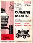
ISears I
owners
manual
. ,. ;."
.
'.
.. .
MODEL NO.
1'· 917: 25752
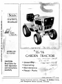
'~. 55/16
GARDEN TRACTOR
CAUTION:
Read Rules for
Safe Operation '
·and Instructions
,.Carefu lIy
• Asse mo " .-..• Operating
• Maintenance
• Repair Parts
Sears, Roebuck and Co., Chicago, Ill. 60684 U.S:A.
l _a nd Simpsons Sears Limited, Toronto ,
.
'.~" ;~
~
another free manual from www.searstractormanuals.com
~)
GUA·RA,NTEE
another free manual from www.searstractormanuals.com
Your Tractor is guaranteed for one full year. If any defect in material or workmanship
should appear during this time, simply contact our nearest Sears store or service center
throughout the United States or Canada. We will make all necessary repairs, including
parts and labor, at no charge to you. Tractors equipped with batteries: If battery proves
defective and will not hold a charge, in exchange for the battery, we will: During the
first 90 doyS'-replace battery at no charge. After 90-days-replace battery, charging customer 1I12th of the price of the new battery for each full month from date of sale.
t
~
I
i
1
If the tractor is used for commercial or rental purposes, this guarantee appl ies for thirty
days.
IMPORTANT
rules for safe operation
TRAINING
1. Read the Owners Manual carefully and fully
familiarize yourself with the controls and
proper use of your tractor as well as any attachment. Be prepared to stop the engine and
powered attachment(s) on a second's notice.
Only persons well acquainted with these Rules
for Safe Operation should be allowed to use
your tractor.
}
2. Do not allow children or young teenagers to
start or operate your tractor.
;/iJtt
3. Do not allow anyone in the area whil8!1 operating your tractor. Keep the children and
pets in the back yard while usin9 it in the
front yard. Keep a wary eye out for children
or passers-by. Oi sengage the power to all
attachments and stop the engine while they
are in the vicinity of your tractor. Children,
particularly, could get in the way of and inlured by the tractor or an attachment.
7.
8.
9.
10.
PREPARATION
4. Do not operate the tractor when barefoot or
wearing open sandals. Always wear substantial
footwear, preferably steel-toed shoes. Also,
do not wear loose fitting clothing that could
3et caught in moving parts.
5. Check your fuel supply before each use. Never
remove the gas cap or fill the gasoline tank
when the engine is running or while it is hot.
When filling the fuel tank, leave space for
expan sion, do not fi II it to the brim and keep
in mind that the heat of the sun can cau~e the
gasoline to expand. Wipe off any spilled gasoline before starting the engine. Rememl;."",,'
gasoline is highly flammable and must always
be handled with extreme care.
6. A tractor and all attachments are precision
4824R-7. 1.
7A
1L
12.
pieces of equipment, not playthings, therefore
extreme caution must be exercised at all times.
Never attempt to operate a damaged tractor or
attachment, always repair any damage before
attempting to start or operate your tractor or
attachment.
Never CTTempt to carry any passengers, their
safety as well as your safety will be endangered.
Before attempting to start the engine of your
tractor make sure the'- gear shift lever is in
neutral and the power to all attachments is
disengaged, then firmly apply the foot brakl!
and be sure to release the parking brake. The
parking brake must always be disengaged when
you put the tractor in motion. If th" tractor is
operated with the parking brake engaged serious
damage may result.
Each time before leaving the operator's seat,
be absolutely sure the power to all attachments
is disengaged, the parking brake is engaged,
the gear shift lever is in neutral, the engine
is shut off, the attachments and all moving
parts have completely stopped and the i gn it ion
key is removed. Never leave the operator's
seat with the engine or any powered attachment
running. Always get on or off your tractor from
the operator's left-hand side.
Always operate your tractor In daylight; dusk
or dark - use your lights.
Operate your tractor at safe speeds on wet or
slippery surfaces, where traction is unsure.
Never at a speed which could cause a skid.
OPERATION
- 1 _
13. Do not atten,,)t to change the governor setting
or overspeed the engine. The governor controls
the engine speed and protects the engine from
:lamaging, excessive speeds. Excessive engine
speeds are dangerous.
14. When startinse',Q~r engine on tractors equipped
\
another free manual from www.searstractormanuals.com
another free manual from www.searstractormanuals.com
rules for safe operation (cont.)
with a pu II starter, stand firm and make sure
your feet are well away from a II powered attachments.
15. Never place your hands or feet in or under any
powered attachment or near any moving ports
wh i Ie the tractor or any powered attachment
is runn in~.
16. Always disengage the power to all attachments,
set the parking broke, shift into neutral, shut
off the engine, make absolutely sure any powered attachment and all moving ports have completely stopped and remove the ignition key
each time you dismount your tractor, even for
a second. Children, yourself, other persons or
pets may be endangered.
17. If your tractor or any attachment should inadvertently strike a foreign object, immediately
disengage the power to the attachment, set the
parking broke, shift into neutral, shut off the
engine, make absolutely sure any powered
attachment and all moving parts have completely stopped, remove the ignition key, disconnect the spark plug wire from the spark
plug and keep the wire oway from the plug to
prevent injury or accidental starting, then
thoroughly, inspect the tractor or attachment
for any damage. Such domage must be repaired
before restarting and operating the tractor or
ott ac h me nt .
18. If the tractor or any powered attachment shou Id
start to vibrate abnormally, place the control
lever for powered attachments in the disengaged
pos ition, set the parking brake, shift into
neutral, shut off the engine, make absolutely
sure the powered attachment and all moving
parts have completely stopped, remove the
ignition key, disconnect the spark plug wire
from the spark plug and keep it away from the
plug to prevent injury or occidental starting,
then check immediately for the cause of this
vibration as vibration is generally a warning
of trouble.
19. Before adjusting, cleaning, repairing or inspecting your tractor or any powered attachment, disengage the power to all attachments,
set the parking brake, shut off the engine, make
absolutely sure the powered attachments and
all moving parts have completely stopped,
remove the ignition key, disconnect the spark
plug wire and keep it away from the spark plug
to prevent injury or occidental starting.
20. Do not run the engine indoors because the
engine exhaust fumes contain carbon monoxide
which is a tasteless, odorless, deadly poison.
21. Never operate your tractor upon a terrace,
slope or incline that is too steep to preserve
good stability and control in order to prevent
tipping or sideways upsets. Always operate a
tractor up and down such an incline, at a slow
speed, do not operate it across. Always exercise extreme caution when changing direction
on inc Iines. Never attempt to operate your
tractor on steep terraces, slopes or inclines
with more than a 15 degree slope.
22. Do not start or stop suddenly when going up or
down a terrace slope or incline. If it is necess ary to stop your tractor upon an inc line,
do so firmly to prevent the tractor from picking
up speed during declutching and before reaching the broke position. Do not shift gears while
4824R-7. 1. 74
23.
24.
25.
26.
27.
28.
29.
30.
31.
32.
ng up 0 .. down inclines. Choose a gear low
ugh to negotiate the incline without stop"
ping and shifting gears. To reduce the speed of
the tractor on an incline move throttle lever to
slow.
Never attempt to operate your tractor or any
attachments without the proper shields, guards,
plates or other protective devices in place and
fully functioning.
Before and while attempting to bock up, look
carefully to be absolutely sure that children,
bystanders, pets, foreign objects or obstacles
of any kind are not beh ind you.
Never allow anyone near the tractor or any
attachment while they are operating.
Be sure to exercise special care when operating
your tractor around fixed objects in order to
prevent the tractor or any attachment from
striking them. Never deliberately run a tractor
or an attachment into or over any foreign objects.
Use care when pulling loads. Use only approved
drawbar hitch points. limit loads to those you
can safely control. Do not turn sharply. Use
counterweight or wheel weight(s) when suggested
in the attachment Owners Manua I.
Never shift gears to reverse your direction of
travel until the tractor comes to a complete stop.
Always stay alert to avoid holes in the terrain
and other hidden hazards. Tipping or sideways
upsets can happen easily in holes or ditches.
Use low gear on unfamiliar ground. If the tractor
or any attachment becomes stuck in a hole
always disengage the power to all attachment~
before attempting to free it.
The use of any precision piece of power equipment requires your full concentration and attent ion to the job be ing done in order to prevent injury or damage.
Always disengage the power to all attachments
when not actually in use sltch as when crossing
a grovel drive, sidewalk or roadway or when
tran sport ing the tractor.
Watch out for traffic when crossing or near
roadways.
MAINTENANCE
·2·
33. Keep all nuts, bolts and screws tight in order
to be sure that the tractor and any attachment
is in safe working condition. Be sure the brake
and all powered attachment controls are always
in proper adjustment and repair. Check the
attachment and engine mounting bolts at frequent interval s for proper tightness. Before
performing any maintenance, always disengage
the power to all attachments, set the parking
brake, shift into neutral, shut off the engine,
make absolutely sure the powered attachment
and all moving parts have completely stopped,
remove the ignition key, disconnect the spark
plug wire from the spark plug and keep it away
from the plug to prevent injury or accidental
starting. The only exception to this rule is
carburetor adjustment, page 12.
34. Keep the engine free from accumulations of
grass, leaves or excessive grease as these
accumulations are combustible and could result
in a fire. Always keep your tractor and all
attachments in good operating condition and
make sure that all shields, guards, plates and
rules for safe operation «Ont~)
other protective devices are in place. Give
your tractor and all attachments the regular
maintenance they need and have a competent
serviceman make a thorough inspection of them
at least once a year.
35. Do not store your tractor for prolonged periods
(more than 30 days) with gasoline in the tank.
Do not store your tractor or a g asol ine container inside a building where fumes may reach
an open flame or spark, they should be stored
in a cool, dry place. Be sure to let the engine
cool before storing in any enclosure. Always
use an approved gasoline container for storing
gasol ine and keep your tractor, attachments
and gasoline container in locked storage to
prevent children from playing and tampering
with them.
another free manual from www.searstractormanuals.com
introduction
This tractor has been designed, engineered and manufactured to give you the best possible dependability and performance.
Should you experience any problem you cannot easily remedy, please contact your nearest Sears, Roebuck and Co, or
Simpsons Sears, Ltd. Store. They have well qualified, competent trained technicians and the proper tools to service
or repair this unit.
It is important that the operator ALWAYS OBSERVE THE "RULES FOR SAFE OPERATION" as well as other
instructions contained in this Manual. We have provided this Manual to help you operate your Tractor with utmost
efficiency. We urge you to study this Manual so you will understand your new Tractor thorCAJghly before operating it.
We suggest that you take care of your Manual so that it will be available for future reference should you need it.
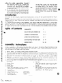
table of contents
GUARANTEE
RULES FOR SAFE OPERATION
1 ·3
ASSEMBLY INSTRUCTIONS
3.5
OPERATING INSTRUCTIONS
5 ·7
MAINTENANCE INSTRUCTIONS
8 • 14
REPAIR PARTS
15 - 33
assembly instructions
A letter in paranthesis in the following instructions refers to an arrow in the adjoining Figure (illustration), except
when otherwise stated. When R.H. (Right Hand) or L.H. (Left Hand) is used, it should be understood to mean as if
one were seated on the Tractor seat facing forward.
1. Remove battery. Cut banding holding Tractor to bottom of crate.
2. Your Tractor has been completely assembled at the factory except, to fill, charge and install the battery and install steering wheel. The battery was shipped dry. Instructions are given on page 4 for filling, charging and insta 11ation,
3. Your Tractor 'was lubricated at th~ factory however, we suggest you follow the Lube Chart on page 10 before
operati on.
4. Tires were over-inflated for shipping purposes. Reduce air pressure to 12 Ibs. in front tires and 12 Ibs. in rear
tires. This will improve traction and give you the comfortable ride you will want.
5. A plastic bag of parts was shipped with your Tractor and should be opened at this time. It will contain the following items:
2 - Hex Nuts
1 • Battery Clamp
(They secure ground strap and positive cable
to battery. They are used in steps 6 and 7,
2 - Wing Nuts
2 • Battery Bolts
page 5).
2 - Flat Washers
2 • Ignition Keys
(We suggest one key be removed from the wire
(These items hold battery in JXlsition on Tractor.
They are used in steps 3 and 5, page 5).
ring and kept in a safe place. Position the
second key in the Tractor ignition).
1
....!oodruff Key
1
Hex Bolt3 i 8xl
Used to hold
1
Washer li16x 1 x 10 Ga.
Steering Wheel
1
Lockwasher 3/8
in place
1
Steering Wheel Cap
4824R.7.1.74
-3-
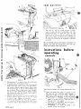
fill and
charge
now be safe to dispose of this down a regular
sewage system. Since the product is well neutralized, no criticism from authorities should
result.
It is preferable, where permissible, to burn the
empty acid pack to prevent possible further contact with acid.
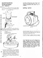
battery
CAUTION: DO NOT ASSEMBLE BATTERY TO
TRACTOR UNTIL BATTERY HAS BEEN FILLED AND CHARGED.
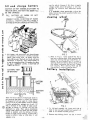
FILL
BATTERY AS SHOWN DO NOT
OVERFI LL--CORRECT LEVEL IS BOTTOM OF TUBES
IN CELLS. - OVER FILLING WILL RESULT
IN WIRE OR PAINT DAMAGE ON TRACTOR.
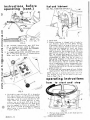
steering
wheel
~
(S
®
another free manual from www.searstractormanuals.com
I
FIG.2
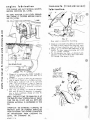
1. Fill battery with electrolyte and charge battery
as out I ined in instructions in battery container.
NOTE: After filling cells, let battery stand for
thirty (30) minutes. Recheck acid level, add more
electrolyte if necessary, then charge battery at
a rate not exceeding three (3) amperes for about
2Y2 hours. CORRECT LEVEL IS BOTTOM OF
TUB ES IN CELLS.
1. Refer to F ig. 2. Insert woodruff key (C) in
key way ot steering shaft. Slide steering wheel
down over steering shaft and woodruff key. Important : Be sure woodruff key is in place in
steering shaft and steering wheel. Secure with
flat washer, lockwasher and hex bolt. Tighten
bolt securely. Press steering wheel cap (D)
b a tt°,;;s;ion i"nc;n;e~0; Is~e;ii~w~eel.
CUT-AWAY VIEW
OF BATTERY
~"-BATTERY
_--_
TUBE
----------------------------..------ - - .........
~--
..........
..........
..........
-- ----------------....----------....
..-...
..........
-...",--
-::_:.,~Z ,:::-~~~ BATTERY
CELL
ELECTROLYTE
FIG. 1
There will be an amount of electrolyte (acid) in
the container after battery is filled. This should
be disposed of and not u sed at a I ater date to
refill Tr()ctoror any other battery. Using a common
5 gallon polyethylene garbage can or pail, fill
with a minimum of four inches of water. Avoid
spillage on person or clothing, add left over
electrolyte to water. Then sod i um b-i carbonate
(baking soda) shou Id be added and the mixture
stirred or agitated until the addition of bicar.
bonate no longer causes foaming. Agitate with a
wooden or plastic stake or stick only. It will
4824R-7. 1.74
FIG.3
1. To lift hood assembly (A), grasp each side of
hood at rear and pull outword and upward. Lift
hood to its extreme forward position.
2. Remove tape holding plastic tray (B) in tractor.
-4-
seat position
E
another free manual from www.searstractormanuals.com
c
1.
The seat (A), may be moved forward, or backward, to give the most comfortable, and safe
operating position. To move the seat, tip seat
forward, as shown in Fig. 6. Loosen nut (B)
slide seat (A) to desired position. Tighten nut
(B) securely. Make sure that seat plate weldment
(C), has not twisted out of alignment, with seat
spring (D).
We recommend wax i ng the tractor to protect it's
beauty, just like you would wax your new car.
Keep your tractor clean and waxed.
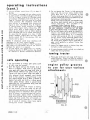
instructions before
operating
FIG.4
controls
G
FIG.5
4.
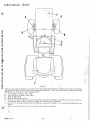
Place battery (C) In piastic tray (B) with battery
termina Is to rear af tractar as shawn.
5. Assemble battery clamp (D~ to one,of the two (2)
battery bolts (E) with a 5;16 x 3.4 flat washer,
and wing nut above clamp as shown. Hook lower
end of battery bolt in slot in side of battery support a s shown. Place c lamp across top of battery,
and secure other battery bolt to battery support
and clamp with other flat washer, and wing nut.
Tighten winq nuts securely.
6. Connect cable and cover (F) Fig. 5 to plus (+)
term i na I battery. Secure with 14 hex nut found
in plastic bag. Tighten nut securely.
7. Connect ground cable (G) (Fig. 5) to negative
(--) terminal of battery. Secure with other 14 hex
nut found in plastic bag. Tighten hex nut securely.
4824R·7.J,; 74
FIG.7
-5-
The following controls are used to operate the Tractor:
1. Clutch and brake foot pedal is located on the
left side foot rest. The foot pedal operates a
combination brake and drive clutch. There are
three positions of operation on the foot pedal.
a. The clutch is in DRIVE position when the
pedal is all the way out (when the foot is
removed from the pedal).
b. The clutch is in NEUTRAL when the pedal is
depressed half way or more.
c. The BRAKE is on when the pedal is depressed all the way forward.
instructions before
(cont.)
fuel and lubricant
OIL FILL TUBE AND DIPSTJCK~~
~~--- -~--.
.;)
~~
- ~
.....""--1~~~
another free manual from www.searstractormanuals.com
-I
FIG. 10
1.
2.
2. The transaxle (transmission) gear shift lever
(A), is located at front, center of seat.
a. The gear shift lever selects the FORWARD,
NE UTRAL and REVERSE gears.
3. To engage parking brake, pull park brake lever
(B), to rear (lock) position. To release parking
brake, push lever (B), forward.
Rai se hood.
Engine crankcase is shipped with oil ready for
use. However, check oil level before starting.
If necessary, add oi I to bring oil level up to full
mark on the dipstick. Dipstick must be pushed
down tight for checking oil level, and tractor
should be level. NOTE: Do not fitl above full
mark on dipstick. Use Allstate S.A.E. 30 oil or
equivalent for summer use. For winter use, below
320 , use Allstate Multi-grade oil S.A.E. 5W-30,
lOW or equivalent. Nothing should be added to the
recommended oil. Make sure the oil used is a
high quality detergent oil classified "for service
MS, SO, SC or SE. Because of recent changes in
the classifications, the oi I container may show
one or a combination of these recommended classifications. CAUTION: Do not overfill crankcase.
Do not use service DS oi I. Do not mix brands nor
grades of motor oi I.
3. Fill fuel tank with a good grade of fresh, CLEAN,
regular gasoline. Wipe off all spilled fuel and oil.
NOTE: Gas tank is located under tractor seat. Tilt
seat forward, so fuel can be added to gas tank.
Refer to Page 5 Fig. 6,
operating instructions
how
to start and
stop
~
FIG.9
4.
c
The high-low range shift lever (C), is located on
R.H. side of chassis, just forward of rear fender.
The high-low range lever has 3 positions, up for
high-range, center for neutral and down for lowrange. There are 2 neutral positions in transmi ssion, one on the gear shift lever (D), and
one on the high-low range lever (C). Both levers
mus t be engaged for Tractor to operate. P Iace
both levers in neutral for pushing of Tractor or
when Tractor is being towed. Refer to "Towing
Tractor", page 7.
B
FIG. 11
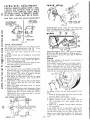
1. Pullout choke control (8), to fuil choke position
to start in co Id weather .
4824R·7. 1. 74
. 6. (CONT. ON PAGE 7),
another free manual from www.searstractormanuals.com
operating instructions
{cont.}
5 . Do not operate the Tractor in high gear going
down hill. Do not turn sharp corners while
going down hill. If it is necessary to stop
Tractor while going down hill, do so quickly to
prevent Tractor from picking up speed during the
declutching to brake pos ition.
NOTE: The engine produces considerable braking action when throttled back to idling speed
without declutching . This procedure is recommended before applying brake.
DO NOT OPERATE TRACTOR ACROSS SLOPES.
DO NOT OPERATE TRACTOR UP OR DOWN
SLOPES WITH MORE THAN A 15 DEGREE SLOPE.
6 . Dc not shift gears while going up steep hills.
Choose a low enough gear to climb hill without
stopping and shifting gears. If it is necessary
to stop while going up hill, do so quickly to
prevent Tractor roll i ng bac k ward. Before starting Tractor in motion going uphill, use one of
the lowest gears. Reduce engine speed and engage clutch gradually to pre vent Tractor from
.
,.
rearing up .
7. Upsets can happen easi Iy in ditches. Stay alert
for holes or other yard hazards.
2 . Ad va nc e throttle c ont rol lever (C ), to about )'2
thr o ttle ,
3. Th is Tractor is equipped w ith two safety switches . One s witch is located on the gear shift lever
(D, F ig. 9, Page 6, at floint E ). The other switch
is loc a ted on attachment clutch lever (C, Fig. 3,
Page 4) . The gear shift lever must be in neutral
(cent e r po s ition ). The attachment clutch le ver
must also be in disengaged (out ), position for
eng ine to start. Turn key ( F, Fig . II, Page 6),
in ign ition-starter switch clockw i se to engage
starter . When engine starts, release key. After
engine starts, push in choke control as engine
warm s up. Let engine warm up before apply ing
load. CAUTION: Do not run starter continuously
for more than 30 seconds at a time. If after
sev eral attempts, eng ine does not start, move
throttle control (C) , to fast position. Wait two
minutes and try aga in.
NOTE: If attachment clutch le ver interferes with
attachment to be used, remove handle.
CAUTION: First mo ve handle to "OUT" positi o n ,
then remove nut and handle. Save for use with attachment for which it is required.
4. To stop engine, turn ignition key in a countercloc kwise direction to OFF position. Key should
be remo ved to pre vent unauthorized operation .
.,
8.
If tractor becomes mired in a hole , try to back out
rather than dri v ing forward .
towing
tractor
1. Place gear shift lever and range shift lever in
neutral posit ion. Tractor can then be towed at
a reasonable safe speed not faster than 6 miles
per hour .
safe operating
.
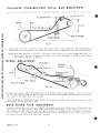
1. Try your Tractor in a large, open space. Learn
engine pulley grooves
to use for your various
attachments
to start, stop and reverse.
2. Start the engine and put the throttle lever at
about 1/ 3 throttle. Push down on foot pedal,
move gear sh ift lever and range sh ift lever to
speed desired. Release foot pedal slowly, and
Tractor will start to move. After foot pedal is
fully released (clutch engaged), move throttle
lever to fast pos ition. If ground travel is too
fast, reduce throttle lever to about Y2 throttle or
depress foot pedal and shift to a slower ground
travel speed. Always select a ground travel
speed that will suit attachment be ing used and
not overload the eng ine.
3. Do not shift gears while Tractor is moving .
4. To stop Tractor, pu s h foot pedal all the way
down and reduce throttle lev er to about Y2 throttle .
Dise ngage power to attachment. Mo v e gear shift
lever to neutral, set parking brake lock and release foot pedal. Always check to make sure
brake lock will hold Tractor secure . Shut-off and
remo ve key fr om switch. This will prevent unauthor ized operation. Keep key in a safe pla c e
out of reach of chi Idren. Ne ver lea ve eng ine
running w ith Tractor unattended .
ENGINE
ENGINE
PULLEY
MAIN DRIVE BEL T
TO TRANSMISSION
SICKLE BAR MOWER
ROTARY MOWER
ROTAR Y SNOWPLOW
ALTERNATOR
SHREDDER---..J
FIG. 12
4824R-7. 1. 74
-7-
~
COMPO ST MILL
ROTARY SWEEPER
POWER SPRAYER
maintenance
instructions
CAUTION: NEVER RUN THE ENGINE WITH
THE AIR CLEANER REMOVED. DIRT WILL
ENTER THE ENGINE AND SCORE THE CY·
LlNDERS.
air cleaner
CAUTION: If air cleaner becomes too dirty, engine
will not receive sufficient air to run properly. Symptoms. Loss of power, flooding, hard to start and overheating.
'I:rV-' WING NUT
cooling system
~~
another free manual from www.searstractormanuals.com
COVER
~, ~~))
'~.'."
"~'
...
..
\
'~-.--~~,~
POLYURETHANE
PRE-CLEANER
HOSE
CLEAN OUT
CHAFF AND DIRT
INTAKE
FIG. 15
FIG. 1'3
This engine is equipped with a paper element and 'J
polyurethane precleaner that must be removed, cleaned and oiled every 25 hours of operation, or more
under extremely dusty conditions.
COOLING SYSTEM: Check and clean cooling fins at
least every 50 hours. Remove any dust, dirt o'r oil
which may have accumulated. Remove any chaff from
rotating and stationery blower screen.
1. WASH
2 SQUEEZE DRY
3. COAT WITH OIL
4. INSTALL
CAUTION: Plugged or clogged cooling fins or blower
screens can cause overheating and engine damage.
THIS TRACTOR HAS AN AIR COOLED Et~a
GINE. AIR MUST BE ABLE TO CIRCULATE
FREELY AROUND THE ENGINE, THROUGH
THE SCREEN GUARD AND GUARD (ROTARY
SCREEN), AND OVER THE FINS OF THE
CYLINDER BLOCK_ KEEP THESE AREAS
FREE OF ACCUMULATED DIRT AND TRASH
OR THE ENGINE WILL OVERHEAT AND
RESULT IN DAMAGE TO ENGINE ..
FIG. 14
To clean pre-cleaner wash in water and detergent
referring to Figure 14. Remove excess water by
squeezing like a sponge and allow to dry thoroughly. Distribute three tablespoons of SAE 30
eng ine 0 i I even Iy around the pre-c leaner. Knead
into and wring excess oi I from pre-cleaner.
2. Depending on conditions in which the tractor is
operating, the inner paper element should be replaced whenever it becomes excessively dirty.
4824R·7.1.74
-8-
engine
transaxle
lubrication
(transmission)
lubrication
STOP ENGINE AND WAIT SEVERAL MINUTES
BEFORE CHECKING OIL LEVEL.
BE SURE TRACTOR IS ON LEVEL GROUND
AND ENGINE IS STOPPED BEFORE CHECKING OIL LEVEL.
I
another free manual from www.searstractormanuals.com
OIL FILL TUBE AND DIP5TICK~
DRAIN ~-.. ..."
_____ PLUQb
FIG. 17
Rear wheel is removed for ill ustrating.
1. Check oi I in transaxle every 50 hours of operation.
To check oil level, remove filler plug from transaxle. Oil level should be even with this plug.
2. Change oil in transaxle after 500 hours of operation. To drain, remove drain plug and catch
oi I in suitable container.
3. To fill transaxle, use 5 qts. of Allstate S.A.E.
30 motor oil for service MM or MS or equivalent.
Fill through filler plug as shown.
[lfQfQ)~
BEFORE
1.
Change oil in crankcase after FIRST 2 HOURS of
operation. Engine should be warm when oil is
changed.
2. To drain oil, unscrew oil drain plug at lower R. H.
side of engine. Catch oil in suitable container.
3. Refill engine crankcase with oil as instructed
under "Fuel and Lubricant", page 6. Capacity
4 pints. Check oil level after each 8 hours of
operation and add oil, if necessary, to bring to
correct level on dipstick.
4. After first oil change, oil should be changed
after each 25 hours of operation. In extremely
dirty or dusty conditions, change oi I every 15
hours of operation.
B.ACKING __ -
NOTE: THE BEST TIME TO DRAIN OIL IS AT
THE END OF A DAY'S OPERATION AT WHICH
TIME THE OIL IS HOT AND ALL DIRT AND
FOREIGN MATERIAL IS SUSPENDED IN THE
OIL.
IMPORTANT: BE EXTREMELY CAREFUL TO
PREVENT DIRT OR FOREIGN PARTICLES
FROM ENTERING THE ENGINE CRANKCASE
OR TRANSMISSION WHEN CHECKING OIL
LEVEL OR CHANGING OIL.
- Q-
lubrication
c hart
,., I
,'r~-E
A
another free manual from www.searstractormanuals.com
A
B
8
C
~--=====::::::::-\-\--H---D
/
.-/
F
FIG. 18
There are only 6 grease fittings on your tractor. Give each grease fitting 2 shots of grease every 5 hours of operation.
Use high performance extreme pressure lubricating grease Amdex No.1. This may be obtained by ordering part number
2557R from your local Sears store or Catalog outlet.
A B C -
Front Wheels (2 fittings, both sides)
Front Spindles (2 fittings, both sides)
Steering Bell Crank
D - Steering Gear Sector and Arm
E - Check oil in engine crankcase at least every 8 hours of operation. Change oil every 25 hours of normal operation.
In extremely dirty or dusty conditions, change oil every 15 hours of operation.
F - Check oil in transaxle (transmission) every 50 hours of operation. Change oil in transaxle every 500 hours of operation.
Apply se v eral drops of oil to all pivot points every 5 hours of operation.
4824R·7. 1. 74
• 10 •
transaxle
(transmission)
drive
belt adiustment
A new belt will stretch after the first few hours of operation, then after initial stretch, ad1ustment
sary.
IDLER BRACKET
IS
seldom neces-
IDLER PULLEY
_-----::l...+oe~
another free manual from www.searstractormanuals.com
7 1/2"
~ TOP OF FRAME
FIG. 19
1.
Loosen bolt in flat idler and frome, and push idler and bolt down in slot 01 frame until center of idlerpulleyon
idler bracket (just back of engine), is7h inches above frame as shown. Tighten bolt in flat idler and frame securely.
NOTE: Foot pedal should be in vertical or just back of vertical position with clutch engaged. New belts will
stretch after a few hours of operation, then after initial stretch, adjustment is seldom necessary. Adjust
belt <lIter first 10 hours of operotion.
brake
adiustment
........_ ...., /'
/ ' DRIVE BELT
-----.
IDLER
PARKING
PULLEy---~_~RAKE ~
------ ------
PARKING LOCK
ASSEMBL Y
5 3/8"
I
FOOT PEDAL
TOP OF FRAME
FIG. 20
To adjust brake, loosen nut back of turnbuckle and turn turnbuckle (clockwise when standing in front of tractor), one
turn at a time until foot pedal has about 4 inches 01 travel from clutch engaged to lull brake position, or center of
idier is about 5 3/8 inches above frame as shown.
Tab on idler bracket will deflect belt slightly. Tighten jam nut against turnbuckle to lock turnbuckle in position.
brake properly adjusted especially in hilly
park
brake
lock
Keep
adlustment
To tighten parking brake ioosen hex nuts (A and B). Rotate parking lock lever to lock position. By hand press foot
pedal forward to full brake position. Whi Ie holding brake pedal forward tighten nut (B), against bushing IC), finger
tight. Release foot pedal, and turn nut (B)' back against bushing (C)' two additional turns. Tighten nut (A), against
nut (8), to lock in position. Place high-low lever in neutral position. Pull parking lock lever back lock) position.
Rear wheels of tractor should slide when tractor is pushed.
4824R-15.2.74
- 11 -
spark
carburetor adiustment
CAUT ION: WHEN FOLLOWING STEPS 1 THRU
5 BELOW, USE EXTREME CARE TO AVOID
CONTACT WITH MUFFLER, HEAT SHIELD
OR MOVING PARTS TO PREVENT INJURY.
ALSO, BELT GUARD MUST BE IN PLACE.
MAIN FUEL AND IDLE VALVE ADJUSTMENT
MAIN FUEL
(HIGH SPEED)
ADJUSTMENT
another free manual from www.searstractormanuals.com
LOW SPEED SET
ON GOVERNOR
LlNKAGE- SMALL
GAP HERE AT NO
LOAD
SPARK PLUG GAP
0.025" GASOLINE
FIG. 23
SPARK PLUGS: Check, clean and reset spark plugs
every 100 operating hours. Replace spark plugs that
show signs of fouling or electrode erosion .
.025
(cold)
THROTTLE
STOP
SCREW
IDLE
ADJUSTMENT
REAR VIEW
SIDE VIEW
FIG.21
INITIAL ADJUSTMENT:
The carburetor has a main fuel valve adiusting screw
and an idle valve adjusting screw. (Fig. 21).
A low
speed adjustment screw is shown in (Fig. 22).
BREAKER POINTS: Check, clean and reset breaker
points every 200 operating hours. Replace points if
they are pitted or burned. Set point gap to .025 cold
when fu Ily open.
1.
Turn main fuel valve clockwise until it just
closes.
CAUTION: Valves may be damaged by turning then
in too far.
2. Now open main fuel valve 1 turn counterclockwise.
3. Close idle valve in same manner and open it
5/8 turn (counterclockwise).
4. Thi s initial adjustment wi II permit engine to start
and warm up prior to final adjustment.
tire s
air pressure in
FINAL ADJUSTMENT
1.
Turn main fuel valve in until engine misses (lean
mixture), than turn it out past the point where en·
~ine runs smoothly until engine runs unevenly
(rich mixture). Turn valve to mid·point between
I ean and ri ch so eng i ne runs smooth Iy.
2. Hold engine at idle position and set low speed
adjustment screw (Fig. 22)
until a fast idle is
obtained (1200 rpm).
3. Hold throttle in idle position and turn idle adjust·
ment valve in (lean) and out (rich) until engine
idles smoothly.
4. Reset low speed adjustment screw so engine
idles at 1200 rpm.
5. Re lease thrott le·eng i ne shou Id acce lerate without
hesitation. If engine does not accelerate properly,
readjust main fuel valve by turning out slightly.
IMPORT ANT: Do not open more than
yond maximum power point.
LOW SPEED ADJUSl MENT
0©J~===-=Q.m
o
-
tires.
G --'-+-'--11
To remoy.£, a front tire and wheel, proceed as fol·
lows:
1. Block up Tractor rocker bar (front axle) securely
Y2 turn be-
or use a Sears Tractor Jack.
2. Remove hex bolt (A), and dust cap (8).
3. Remove gripco nut (C), wear washer (D), pin
(E), and washer (F), from spindle shaft as·
sembly (G).
4. After tire is repaired, reverse above procedure
. . . . .-
1__
for reassembly.
A rear whee I and tire is removed by remov i ng the
five hub bolts from wheel and hub. FI RST: Block
up rear axle securely or use a Sears Tractor Jack.
Sears or your local service station can repair your
Tractor tire in the same manner as an automobile
SET LOW SPEED ADJUSTMENT
SO ENGINE RUNS AT 1200 RPM
IN "SLOW" POSITION.
~
4824R·7. 1.74
FIG. 22
• 12.
tire.
trouble. shooting
WILL NOT START
POSSIBLE REMEDY
POSSIBLE CAUSE
Dead battery
Recharge or replace battery.
Attachment c Iutc h lever engaged ......................... .
Move to "out" position.
Gear sh i ft Iever in gear .................................... .
Shift into neutral position.
No g(1sol ine in fuel tank or carburetor
Fill the tank with gasoline; open fuel shut-off valve.
Check fue I line and carburetor.
another free manual from www.searstractormanuals.com
HARD TO START
Water in gasoline or old fuel
Drain fuel tank and carburetor. Use new fuel and dry
spark plug.
Choked improperly. Flooded engine •••••.......•.••.....
Push in choke, open throttle control and crank engine several times to clear out the gas.
Dirty air cleaner ............................................ ..
Remove and c lean, refer to page 8.
Spark plug dirty or improper gap •..••....•..••..••.•..•.
Clean, adjust the gap or replace. Refer to page 12.
Defect ive battery ...•...•.........•.....•..•...•......... "' ...
Replace.
Defective ignition or loose wiring
Check the wiring and spark plug.
ENGINE MISSES OR LACKS POWER
Dirty starter air screen
Clean screen over starter, see page 8. Be sure fins
on cyl inder head and around cyl inder are clean.
Partially plugged air cleaner ............................. ..
Remove and c lean, refer to page 8.
Low oil level or dirty oi I .................................. .
Check or change oil, see page 9.
Improper carburetor ad ju stment .••.•.......•...•...••...•••.
Refer to page 12.
Spark plug dirty, wrong gap or wrong type ...•..•.....
Clean, reset the gap or replace.
Engine overloaded ..•.....•..••......•••..•.••..•....•..••.....
Shift to a lower gear or reduce load.
Faulty ignition ...............•.........•.•..............•......
Check spark plug and for loose wires. If trouble
cannot be corrected, contact Sears.
Oil in gasoline ...•................................•..•....•.•.
Drain and refill gbsoline tank and carburetor. Oil
reduces the efficiency of the engine.
Poor compression
Contact Sears.
ENGINE OVERHEATS
Dirty starter air screen
Low oi I level or dirty
C lean screen over starter, see page
0
i I ..............................•..
Check or change oil,
a.
see page 9.
Partially plugged muffler .•........................•.......
Remove muffler from engine and clean.
Poor fuel or too lean a mixture .•.•...................•.
Refer to page 12.
Partially plugged air cleaner ............................ .
Remove and clean,
Dirty engine
Clean fins on cylinder head and around cylinder.
refer to page 8.
NO LIGHTS
No head I ights or tail I ight with I ight switch knob
pulled out ....................................................... .
4824R-7.1.74
Check for loose wires or a short circuit in wirin8
- 13 -
another free manual from www.searstractormanuals.com
important battery
storage
care
instructions
In the event your Tractor is to be inoperative for
periods in excess of 30 days. prepare for storage as
outlined in the next column.
1. Drain fuel tank and carburetor by allowing the
engine to run out of g<lsoline. Gasoline left in
your engine will leave gum deposits and condensation in the carburetor and fuel tank. This
makes fuel system inoperative and will result
in hard or non-storting of the engine.
Proper attent ion to t he battery is of utmost i m·
portance.
The following points are recorded to help remind
you to provide attention to the battery and gain full
advantage of the usable life built into the battery
and avoid costly replacement.
1. Check solution level in battery at least once
each week. Add distilled water when required.
Correct level is bottom of tubes in cells, refer
to page 4. After adding water, run the engine so
that the generator charge will mix the solution.
DO NOT OVERFILL.
Acid spilled from the
battery wi II corrode choke control and throttle
control casing and wire, Tractor paint, etc.
2. Keep the battery clean and dry at all times.
Remove any collection of grease, corrosion or
other substance from the battery.
3. Keep battery snug in its holder.
4. Keep vent caps tight and small vent holes in
caps open.
5. If battery should become discharged or falls
below a specific gravity of 1.225, remove battery
and have it recharged.
6. When recharging, request service station to
SLOW CHARGE the battery at a rate of 3 amperes.
FAST CHARGING IS NOT RECOMMENDED.
2. Lubricate cylinder by removing the spark plug.
pour one ounce of clean lubricating oil through
the spark plug hole into the cylinder. Crank the
eng ine slowly to spread oil and reploce the spark
plug.
3. Clean the engine and Tractor:>f all foreign matter.
4. Do not save or store gasoline over winter.
STORE YOUR TRACTOR IN A DRY AND PROTECTED PLACE. LEAVING YOUR TRACTOR
OUTDOORS, EXPOSED TO THE ELEMENTS,
WILL RESULT IN MATERIALLY SHORTENING
ITS LIFE.
general
1. Just
as your automobile needs professional
mechooical maintenance from time to time, so
does your air cooled engine. Cleaning and
ad i ustment of the carburetor and periodic
replacement of the spark plug and ignition
points is made necessary by NORMAL use.
winter care--battery
1. If Tractor is not used regularly during winter
months,
the battery should be removed and
stored in a cool, dry place above 50 0 F.
2. Professional air cooled engine service is as
close as your nearest Sears Store.
2. Battery should not be placed directly on cement
as this will drain the battery.
3. A yearly check-up or tune-up by Sears is a good
idea to avoid breakdowns or delays.
3. If Tractor is used only infrequently during winter
months, check battery at least once each thirty
days to be sure a full charge is maintained.
4. A battery not fully charged can freeze, resulting
in the necessity to replace.
5. A safe rule is to charge the battery monthly or
at least test and recharge if below 1.225 specific
gravity.
6. Recharge to bring the specific gravity to normal
before replac ing it in the Tractor after storage.
Please remember the necess ity of proper winter care
for the battery. Batteries not in use for several
months and not kept fully charged, produce a sui·
phation of the plates which cannot be removed by
recharging.
Important-V Belt Care
1. To prolong the life of your tractor's drive belts,
the tractor and attachment clutches should be en'
gaged with the engine throttle lever placed at about 1/3 thrott Ie.
Sears, Roebuck and Co. or Simpsons-Sears Ltd. in
Canada reserves the right to make any changes in
design or improvements without imposing any ob·
ligation to install the same upon its items heretofore
manufactured.
2. After the clutches are engaged, the engine throt·
tie lever should be moved upwards to the "Fast"
position for most efficient tractor operation.
AA,)AR.7 L 7A
• 14 •
rep a
•
Ir
p a r·t 5
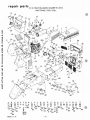
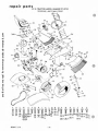
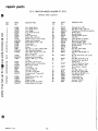
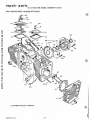
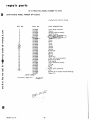
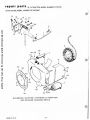
SS / 16 TRACTOR--MODEL NUMBER 917.25752
MAIN FRAME, DASH, GRILL
another free manual from www.searstractormanuals.com
4
27A
\
;3 4 35
36
/
®~
~"
28 29
~/
B
-i'
V
/
IT)
30
GY
Gi '~~~
FY
~~~
''''-37
~)~s 31 33~
50
.~
N ,.k&49
~ L';)/
~~e.( .ll
" 'r
R
:1--.
0:
'rQ
, ~ 48 jldIiiij~~
/'
'( .
L3!
47
31~
51 ~
33 --P ~
22
32 t
:
HI
0
..
/
56
" "
0
5~
.
~
•
0
~
45
~<",W
'']
I
I
I
~ flj)r!'l::\.
I
,~(gL ~
62 6 3 1 \ ~\
/
6465
A
I
B
COEFGH
I
iI:ll
W 'if i """'81
.." 11
---81 .
~
=
""" 11 Z c::::::,8 2
82
83
'9
~83 ~84
II
@86
~
®87
84
22
4824R-7.1.74
K
J
l
M
66
NO
P
Q
R
STU
W !86:86 H lJ ~ ~ If : 83 ~
.al
85
D
87
"""88 ~88 ~88 '~ =22
11:0
IDJ
83 ~ 83
8 8 .:1)8 10)84 £II 84
• 15 •
1t
.,..83
1J
x
VW
0
=83
OJ 84
y
B
~ 11
--83
1IIl
89
DJ
84
~
.90
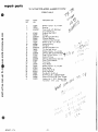
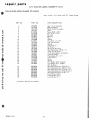
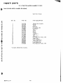
repair parts
5
6
7
8
9
10
11
llA
12
13
14
15
PART
NO.
634A551
5610R
3300R
4821R
634A549
3531R
2695R
504P
582R
3012P
3494R
5348R
2697R
2696R
1998R
634A605
16
2683R
17
18
19
20
21
22
7552H
2682R
4819R
2754R
2686R
1513P
23
24
24A
25
26
2671 R
1545P
5527R
2689R
634A523
26A
27
4815R
634A625
27A
28
29
30
31
32
33
34
35
36
37
4394R
9396E
634A 104
634A527
8704H1
9011 H
4939M
347H
8238H
634A659
3154P
38
39
40
41
42
42A
43
44
45
46
47
48
49
50
51
52
53
54
55
56
57
2672R
2676R
3652R
3653R
2678R
4171R
2673R
2677R
5626R
2794R
2674R
634A28
6485H
2752R
2665R
634A531
634A543
2655R
634A518
2670R
634A355
KEY
NO.
1
2
3
another free manual from www.searstractormanuals.com
4
4824R·15.2.74
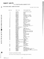
SS/ 16 TRACTOR-MODEL NUMBER 917.25752
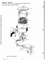
MAIN FRAME, DASH, GRILL
DESCRIPTION
Hood Assembly
Deco I·Hood Str i p
Decal·Sears
Decal (Maintenance Minder)
Muffler Guard Assembly
J·Clip
Muffler
Hex Nut 5/ 16·18 (STD541031)
Clamp.1 3/ 8 (Includes No.8 & 10)
Hex Bolt 5/ 16·18x 1Y.\ (STD523112)
Heat Shield·Carburetor
Sea ling Stri p
Exhaust Manifold·Front
Exhaust Manifold·Rear
CI ip·Dashboard
Dashboard w/ Clips (Includes Item
No. 14 Does Not Include Item No.
19)
Ignition Switch (Includes Item No.
17)
Key Set
Remote Control· Throttle
Dashboard Panel
Choke Control
Battery Troy
Washer 13/ 32x 13/ 16x 16 Go. (STD
551037)
Bracket·Battery Support L. H.
Washer 17/ 32 x 1 x 16 Go.
Muffler Guard Brocket
Bearing
Battery Support & Id ler Support
w/ Bearings
Battery Heat Shield
Engine 16 H. P. (Twin Cyl) Mod;1
BF·MS2666C
Grill Brace
Sq. Key Y.\ x 2
Engine Pulley w/ Set Screws
Belt Guide Weldment
Spacer
Belt Retainer
Reta i ner Spr i ng
Huglock Nut Y.\·20
Split Spacer
Belt guard weldment
Slotted Fillister Hd. Mach. Screw
Y.\· 20 x 2Y.\
Gr ill Screen·Upper
Grill·Upper
Decal·Grill Top (SS/ 16)
Decal·Grill (Twin)
Grill Side
Insulated Clip
Gri II Screen·R. H.
Grill·Lower
Gri II Stop
Gri II Screen·Center
Grill Screen·L.H.
Front Channel Cover & Weld Bolts
Hinge
Front Channe I Cover Support
Grill Spacer
Engine Mount Assy.
Chassis Assy W/Bearings
Cover R. H.
,",
Id ler Bracket We Idment
Bracket·Battery Support R. H.
Hanger Weldment L. H. Front
$'.
- 16·
KEY
NO.
58
59
60
61
62
63
64
65
66
67
68
69
PART
NO.
2702R
9521H
5858R
634A 101
500P
1001P
6635H
1520P
6479H1
1518P
3262P
5501P
70
71
72
73
74
75
76
77
78
79
80
2249R
1003P
6341\492
634A491
5999H
1689E
634A494
4379H
634A493
7810H
3013P
81
82
1002P
1506P
83
84
85
86
87
1004P
501P
1605H
1006P
505P
88
89
90
A
B
1003P
5394H
1001P
503P
3027P
C
D
E
3023P
3008P
3253P
F
5554P
G
H
503P
5564P
J
K
3267P
3122P
L
505P
M
N
0
R
S
T
3010P
3012P
17P
3027P
3022P
501P
3023P
5557P
U
V
3025P
4514P
W
X
Y
28P
3021 P
3035P
53P
p
Q
Z
DESCRIPTION
Shift Pattern Plate
Drive Rivet
Model Plate
Drawbar & Weldnuts
Hex Nut 7/ 16·14 (STD541043)
Lockwasher 7/ 16
Flat Idler
Washer .469 I. D. x 1·1/8x 11 Go.
Belt Guide Finger
Washer 15/ 32 x 11/16 x 16 Go.
Hex Bolt 7/ 16·14x2·1/2
Pan Hd. Phillips Thread Cutting
Screw No. 10·24 x 3/ 8 Type T
Safety Switch
5/ 16 Lockwasher (STD551131)
Switch Brocket Assy
Belt Tightener Arm & Idler Shaft
Spri ng Wa sher
Bushing
Hanger We Idment·R. H. Front
Handle Grip
Blade Clutch Handle Assy
Gripco Locknut 3/ 8·24
Hex Bolt 5/ 16·18 x 111 / 2 (STD
253115)
Lockwasher Y.\ (STD551125)
Washer 9/ 32 x 5/ 8 x 16 Go. (STD
551025)
Lockwa sher 3/8 (STD551137)
Hex Nut 3/ 8·16 (STD541037)
Locknut Y.\·20
Lockwasher No. 10 (STD551110)
Hex Mach. Screw Nut No. 10·24
(STD541010)
Lockwa sher 5/ 16 (STD551137)
Locknut 3/ 8·16
Lockwasher 7/ 16
Hex Nut Y4·20 (STD541025)
Hex Bolt 3/ 8·16 x 1·1/2 (STD
523715)
Hex Bolt 3/8·16 xl (STD523710)
Hex Bolt 5/16·18x 1/2
Slotted Pan Hd. Mach. Screw Y.\·20
x 112 (STD512505)
Phi Ilips Pan Hd. Thrd. Cutting
Screw No. 10·16 x 1/2
Hex Nut Y.\·20 (STD541025)
Phillips Pan Hd. Thrd. Cutting
Screw No. 10·24x 1/2 (STD511005)
Hex Bolt Y.\·20 x 1· 1/2 H. T.
Slotted Truss Hd. Mach. Screw
No. 10·24x 3/ 8 (STD511003)
Hex Mach. Screw Nut No. 10·24
(STD541010)
Hex Bolt 5/ 16·18 x %(STD523107)
Hex Bolt 5/ 16·18 xl Y.\ (STD523112)
Carriage Bolt 5/ 16·18 xl (STD533110)
Hex Bolt 3/ 8·16x1·1 / 2(STD523715)
Hex Bolt 3/ 8·16x7/ 8
Hex Nut 3/ 8·16 (STD541037)
Hex Bo It 3/ 8·16 x 1 (STD52371O)
Hex Wa sher Hd. Thrd. Cutting Screw
Y.\·20 x 1/2
Hex Bolt 3/ 8·16 x 1Y.\ (STD523712)
Hex Socket Hdless Set Screw
5/ 16·18 x 5/ 8
Carriage Bolt 3/8·16 xl (STD533710)
Hex Bolt 3/8·16 x % (STD523707)
Hex Bolt 7116·14x 1Y.\
Carriage Bolt No.10·24x Y2
repair parts
S~/ 16
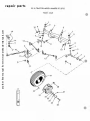
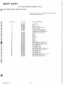
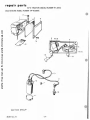
TRACTOR··MODEL NUMBER 917.25752
another free manual from www.searstractormanuals.com
FRONT AXLE
1
1/ 2
(fIJ/
~
8 --------- ®
\
17
A
27
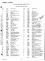
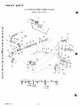
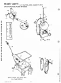
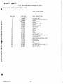
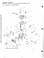
repair parts
1~'
SS/16 TRACTOR··MODEL NuMBER 917.25752
-1~
FRONT AXLE
KEY
NO.
1
2
another free manual from www.searstractormanuals.com
3
4
5
6
7
8
9
10
11
12
13
14
15
16
17
18
19
20
21
22
23
24
25
26
27
28
A
Y..
:J -r~~
c(\
PART
NO.
DESCRIPTION
1528P
1309H
634A521
Washer 13/16 x 11,4 x 14 Ga.
Bearing
Front Axle with Bearings
(Inc. Key No.2)
Huglock Nut 5/8·11
E-Ring
Spindle Complete-R.H.
Flanged Bearing
Gripco Locknut 3/8-24
Washer 9/32 x Y2 x 14 Ga.
Grease Fitting
Hex Bolt
Spindle Complete-L.H.
Tie Rod and Joints
Washer 49/64 x 11,4 x 16 Ga.
f)
Steering Bell Crank Weldment~
11.
Drag Link and Joints - $ ) . I
Grease Fitting
Steering Gear Sector and Arm
Front Tire-Tubeless
Tire Valve
Front Wheel
Washer 25/32 x m x 16 Ga.
Wear Washer
Elastic Nut ~-16
Dust Cap-Outer
Hex Bolt 5/16-18 x Y2
Roll Pin 5/32 x 1 (STD571510)
Grease Fitting Y4-28 Taper Thread
Amdex No. 1 E.P. Grease (Not
I
f,,,;,hed wHh yo", T'0;:fo/3~ ~
4764H
5000P
634A277
9040H
5810H
1505P
6855M
2699R
634A278
1808R
1552P
634A98
9318H
6842M
634A95
2169R
795R
2892R
1562P
8785H
4831H
8763H
3008P
8798H
6856M
2557R
\D'
01
fj,~~
t 7/
~~«1l /
()~
.!
\
.4824R.7. 1. 74
,
- lR .
(/
1U
/)
6
another free manual from www.searstractormanuals.com
•
repair
54
t
::-----.- 53
4824R-7. 1. 74
• 19 •
46
®
47·.---" ~
48
/
()-11
•
parts
repair
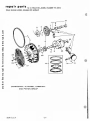
SS/16 TRACTOR--MODEL NUMBER 917.25752
another free manual from www.searstractormanuals.com
e
STEERING, AI'-iD FINAL DRIVE
KEY
NO.
PART
NO.
DESCRIPTION
KEY
NO.
PART
NO.
DESCRIPTION
1
lA
2701R
3023P
2
3
3A
4
5
6
7
8
9
10
11
1559P
4820R
5003P
1552P
900lH
5949H
6468H
634A543
634A281
878lH
9858M1
Steering Wheel Cap
Hex Bolt 3/8.16x 1 (STD
523710)
Washer 7/16x 1 x 10 Ga.
Steering Wheel
E·Ring
Washer49/64x l~x 16 Ga.
Cap
Rubber Bushing
Bearing
Chassis Ass'~ w/Bearings
Foot Rest w/ olts L.H.
Foot Rest Pad L. H.
Woodruff Key 3/16x 5/8 (STD
580020)
51
52
53
54
55
56
57
58
59
60
61
62
62A
63
64
65
66
67
68
69
70
71
72
5000P
6842M
2657R
794R
6477H
6442H
2511P
9204H
2893R
795R
2692R
2656R
3239R
2658R
1003P
5394H
1578P
1560P
1000P
502P
1004P
501P
508P
73
74
75
76
77
1001P
500P
1002P
503P
1513P
78
1506P
79
A
504P
3010P
B
3159P
C
D
E
3022P
25P
20P
F
G
H
J
K
1304H
4524P
3034P
3034P
3010P
L
16P
M
N
503P
501P
4501P
3025P
3023P
3022P
3010P
3003P
3021P
19P
E·Ring
Grease Fitting
Fender R. H.
Rear Tire 23x 9.50.12
Range Shift Rod
Shift Rod Bracket
Cotter Pin 3/16 x 1
~O
Locknut Y2·20
~'f, !(
Rear Wheel
~z.;
Tire Valve
~1"Q ;
V·Belt (Ground Drive)
Bra cket· T a i I Li ght
Safety Std. Sticker
Fender L.H.
Lockwasher 5/16 (STD551131)
Locknut 3/8.16
Washer %x 1·1/8x 11 Ga.
Washer 17/32xlhx11 Ga.
Lockwasher Y2 (STD551050)
Hex Nut h·13 (STD54105O)
Lockwasher 3/8 (STD551137)
Hex Nut 3/8.16 (STD541037)
Hex Jam Nut 3/8.16 (STD
541237)
Lockwasher 7/16 (STD551143)
Hex Nut 7/16·14 (STD541043)
Lockwasher ~ (STD551125)
Hex Nut \4·20 (STD541025)
Washer 13/32x 13/16x 16 Ga.
(STD551037)
Washer 9/32x 5/8 x 16 Ga. (STD
551025)
Hex Nut 5/16·18 (STD541031)
Hex Bolt 5/16·18x% (STD
523107)
Hex Bolt 5/16·18x7/8 (STD
523108)
Hex Bolt 3/8·16x7/8
Carriage Bolt h·13x 1\4 H. T.
Carriage Bolt 3/8.16x 1 (STD
533710)
Hub Bolt
Sq. Hd. Set Screw 3/8.16x 1\4
Hex Bolt 7/16·14x1
Hex Bolt 7/16·14x 1
Hex Bolt 5/16·18x% (STD
523107)
Carriage Bolt 5/16·18x % (STD
523107)
Hex Nut \4·20 (STD541025)
Hex Nut 3/8·16 (STD541037)
Sq. Hd. Set Screw C. P. 5/16·18 x h
Hex Bolt 3/8.16x 1~ (STD523712)
Hex Bolt 3/8·16x 1 (STD523710)
Hex Bolt 3/8.16x7/8
Hex Bolt 5/16·18x% (STD523107)
Hex Bolt \4·20 x % (STD522507)
Hex Bolt 3/8.16 x % (STD523707)
Carriage Bolt 3/8·16x% (STD
533707)
Owners Manual
12
13
13A
14
15
16
17
18
19
20
8)21
22
23
24
25
26
27
28
29
30
31
32
9008H
1062R
8765H
1244R
2648R
4823R
634A532
2663R
634A533
2693R
9769H
815R
5404R
8141H
634A534
2650R
6364H
634A535
6459H
877aH
8327H
633A38
33
34
34A
35
36
37
38
2329R
9772H
5424R
2694R
2751R
634A22A
6461H2
39
39A
40
41
42
43
44
45
46
47
48
49
50
634A362
2521R
634A33A
626A31 A
634A282
2267R
1527P
5001P
8788H
4766H
1553P
634A626
634A95
Sprin~
Fppt edal
Foot Pedal Bracket
Foot Pedal Plate
Foot Pedal Shaft
Seat
Seat Bracket Weldment
Bracket Seat Pivot
Seat Plate Weldment
Fuel Tank
Fuel Gauge
Fuel Line Fitting
Seat Spring
Seat Spring Reinforcement
Neutral Safety Arm Ass'y
Bracket·Fuel Tank
Control Knob
Neutra I Safety Support As s' y
Transmission Bracker
Wheel Hub·Rear
Sq. Key \4x 3
Transmission (Transaxle)
Less Brake Drum
Neutral Safety Switch
Hose Clamp
Recessed Bumper
Fuel Line
Clip.Fuel Line
Belt Guide
Transmission (Transaxle)
Pulley
HanJer. Rear
Insu ated Clip
Brake Arm Ass'y
Steering Arm Ass'y
Foot Rest w/Bolts R. H.
Decal (Attach. Clutch)
Washer 2li32x 7/8 x 16 Ga.
E·Ring
Foot Rest Pad R. H.
Bearing
Washer 57/64x1~x 16 Ga.
Steering ShQft & Pinion
Steering Gear Sector & Arm
0
P
Q
R
S
T
U
V
4824R
4824R·7. 1.74
·20·
V
tJlr{'j..
•
repair parts
SS/16 TRACTOR··MODEL NUMBER 917.25752
another free manual from www.searstractormanuals.com
BRAKE:, AND CLUTCH
~36
ABC
DE
F
G
47i48Y49 V500511]"52 ~ 53
1
~56 =e:>57
~
~59 ~60
~58
-===8
4824R-7. 1.74
• 21 •
H
J
£1)54 y55
~57
•
repair
parts
$5/16
TRACTOR--M{}Q;~L
NUMBER 917.25752
another free manual from www.searstractormanuals.com
BRAKE, AND CLUTCH
KEY
NO.
PART
NO.
DESCRIPTION
KEY
NO.
PART
NO.
DESCRIPTION
1
2
3
4
5
6
7
8
9
10
11
12
13
14
15
16
2648R
1244R
1062R
8765H
5001P
2202R
2505P
1513P
634A33A
9858M1
2645R
2514P
6486H
548P
634A518
634A86
33
34
35
37
38
38A
39
40
41
42
43
44
45
46
47
9071H
3244P
626A341
4379H
5999H
2221R
175H
634A489
626A365
2197R
1557P
2263R
2201 R
501P
6417H
3052P
17
18
19
1545P
626A31 A
1520P
48
4501P
49
50
3159P
llP
20
21
22
23
24
25
26
27
3262P
1518P
6479H1
6635H
1001P
500P
9204H
6461H2
51
3164P
52
2004P
53
54
55
28
29
30
31
32
2228M
7648H1
7645H
634A168
634A 167
Foot Pedal Shaft
Foot Pedal Plate
Foot Pedal
Foot Pedal Bracket
E-Ring
Brake Rod-Front
Cotter Pin 1"g x 3/4
Washer 131.32x13/!6x16Ga.
Brake Arm Assembly
Woodruff Key 3/!6 x 5"g
Clutch Rod
Cotter Pin 14 x 1
Spring
Hex Jam Lock Nut 3"g-24 UNF
Idler Bracket Weldment
Idler, Bolt and Nut (Inc. Key
No's. 14 and 47)
Washer 171.32 x 1 x 16 Ga.
Steering Arm Assembly
Washer .469 I.D. x 1-118 x
11 Ga.
Hex Bolt 7/!6-14 x 272
Washer 151.32xll/!6x16Ga.
Belt Guide Finger
Flat Idler
Lockwasher 7/!6
Hex Nut 7/!6-14
Lock Nut );2-20 UNF
Transmission {Transaxle}
Pulley
Woodruff Key 3/!6 x 3/4
Brake Drum
Brake lining
Brake Bracket Assembly
Brake Band and lining
3022P
51lP
3003P
1003P
1002P
1004P
1685H
503P
Huglock Nut 14-28
Hex Bolt 14-28 x 5"g H. T.
Parking Lock Handle Assembly
Handle Grip
Spring Washer
Parking Brake Spacer
Roll Pin
Lock Bracket Assembly
Brake Rod Assembly
Parking Brake Yoke
Washer 131.32 x 13/!6 x 11 Ga.
Spring Washer
Bushing
Hex Nut 3"g-16 UNC
Turnbuckle
Hex Bolt 3"g-24 UNF x 1
Pltd.
Sq. Hd. Set Screw C. P. 5/!618 x 72
Hex Bolt 5/!6-18 x 718
Sq. Neck Carriage Bolt
14-20 x 5"g
Flat Hd. Machine Screw
Undercut 3"g-16 x 3/4
Rivet, Brass Tubular
,
#4 x 14
Hex Bolt 318-16 x 7"g
Nylock Nut 3"g-24 UNF
Hex Bolt 14-20 UNC x ~
Lockwasher 5/!6
Lockwasher 14
Lockwasher 3"g
Locknut 5/!6-18
Hex Nut 14-20
4824R-7. 1.74
- 22 -
36
56
57
58
59
60
'~'.-
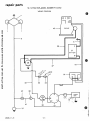
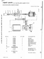
repair parts
SS/16 TRACTOR--MODEL NUMBER 917.25752
'/tIRING DIAGRAM
I I I
II I
I
another free manual from www.searstractormanuals.com
43
1-+---
ENGiNE
8
6--a
20--1
21
BATTERY
+
1
18-
27
19--1
42
--+-I
33
32
POINT
BOX
41
l--15
4824R-7. 1.74
- 23 -
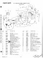
repair parts
SS/16 TRACTOR--MODEL NUMBER 917.25752
ELECTRICAL
£
4
3
f ~ ~ ~2
tfr",'"
~6 .~
44-~
~
/1
~~."'~
~
7
I
10
~
11
another free manual from www.searstractormanuals.com
\
•
9
u /
~
•.C '
12
15
14 13
\
1
26~
~ tP -~
.Ji:
.
~.\ ~@@
.
~%.
~>'
16
\
17
\
(}41
/
39
\
\
37
KEY
NO.
PART
NO.
OESCRI PTION
KEY
NO.
PART
NO.
OESCRIPTION
1
2
7034H
9197H
3
4
5
8784H1
8768H
5554P
23
24
25
26
27
3748M
1509P
5110H
2685R
634A490
6
7
8
2753R
2894R
3773R
Headl ight
Hose (On Grill.Heddlight
Locating Pins)
Rubber Spacer
Mounting CI ip
Phillips Pan Hd. Thread
Cutti ng Screw No. 10·16 x Y2
Battery Cable (Neg. To Ground)
Ground Wire·Headlight
Lead Wire (Light Switch To
eadlight & Tail Light)
using (Tail light)
b No. 18952 Candle Power
3895)
Lens (Tai I Light)
Hex Mach. Screw Nut No. 10·24
(ST054101O)
External Tooth'Lockwasher No. 10
Slotted Truss Hd. Mach. Screw
No. HJ..'24XY2 (ST0511005)
Tail light
Key Set
Ignition Switch (Includes Item
No. 16)
Ignition Wire Harness
Regulator
Battery Cable (Solenoid To
Starter)
Battery
Hex Nut ~4·20 (ST0541025)
28
29
30
31
32
33
34
35
36
37
38
39
41
103R
3004P
1002P
2777R
2329R
2249R
543P
1006P
5212R
5735H
9267H
4853R
5439R
42
2688R
43
634A625
44
1402P
Wing Nut %·20
Washer 5/16x%x 16 Ga.
Battery Clamp
Battery Bolt
Battery Cable & Cover
(Positive to Solenoid)
Solenoid
Hex Bolt Y4·20 xl (ST0522510)
Lockwasher Y4 (ST0551125)
Tie
Neutral Safety Switch
Safety Switch (Mower Clutch)
Hex Nut No. 10·32 (ST0541110)
Lockwasher No. 10 (STD551110)
•
Ammeter
Light Switch (Includes Item No. 38)
Knob Light Switch
Circuit Breaker
Electrical Wire (Fuse to light
Switch)
Electrical Wire (Solenoid to
Ammeter)
Engine 16 H. P. (Twin Cyl.)
Model BF·MS:'666C
External Lockwasher
9
10
11
12
8292H
505P
13
14
1404P
3073P
15
16
17
8089H
7552H
2683R
18
19
20
4854R
2684R
2226R
21
22
5111H3
503P
4824R·15. 2.74
• 24 •
repa •Ir parts
SS/16 TRACTOR··MODEL NUMBER 917.25752
TRANSAXLE
another free manual from www.searstractormanuals.com
4
7
10
9
24
2
I /3
@Q-,
I
-_
I
I
47
--J
148
Q/49
I
19 20
_~_I
~--
\
50
I"
repair parts
another free manual from www.searstractormanuals.com
SS/16 TRACTOR--MODEL NUMBER 917.25752
,TRANSAXLE
fit
KEY
NO.
PART
NO.
DESCRIPTION
KEY
NO.
PART
NO.
DESCRIPTION
lo
633A38
2.
3.
4.
6213H1
4869H1
3010P
38.
39.
40.
8118M
6266H
633A14
5.
6.
7.
8.
9.
10.
1l.
12.
13.
1003P
6254H1
6259H
4924H
1544P
6273H
1525P
2505P
633A 19
14.
15.
16.
6274H
504P
1007P
4l.
42.
43.
44.
45.
46.
47.
48.
49.
50.
51.
52.
53.
54.
6221H
8659H
2228M
633A32
8119M
8275H
633A27
4002P
4003P
9204H
7648H1
6271H
4001P
3087P
17.
18.
6270H
633A28A
19.
20.
21.
22.
23.
24.
25.
992R1
4910H
5855H
6269H
3039R
6256H
7810H
55.
56.
58.
59.
60.
61.
62.
633A33
6276H
4895H
1370H
633A31
633A30
633A 11
26.
27.
28.
29.
30.
31.
633A34
8662H
6252H 1
8657H
6263Hl
3056P
63.
64.
65.
66.
67.
68.
69.
70.
71.
32.
6217H
33.
34.
35.
36.
37.
6260H
6272H
7392M
6215H
6277H
Transaxle Assembly less
Brake Drum
Gear Shift lever straight
Gear Shift Cap
Hex Bolt 5/16-18x% (STD
523107)
Lockwasher 5/16 (STD 551131)
Gear Sh ift Ba II Cover
Shift Lever Guide Ball
Spring
Washer 15/32x59/fl4x16 Ga.
Shift Mechanism Seal
Washer9/16x15/16x11 Ga.
Cotter 1/8x% (STD 561210)
Gear Sh ift Gate and Re infortement
Gasket-Shift Ball Cover
Hex Nut 5/16-18 (STD 541031)
Lockwasher 5/16 Extra Heavy
(STD (551131)
Oil Seal
Gear Case, Reverse Idler Shaft
and Bearings R.H.
Sintered Iron Bearing
Oil Seal
Pressure Relief Valve
Oil Seal
Needle Bearing
Axle Thrust Washer
Center lock Gripco Nut 3/8-24
(STD 541537)
Axle Shaft and Gear
Final Drive Gear
Bushing-Differential Pinion
Differential Pinion
Differential Carrier
Hex Bolt 3/8-24 x 3~4
1" Thread Length
High-Low Range Shift Fork
Shaft
Shift Fork, High-Low Range
Spring-Shaft Fork Detent
Steel Ball
High-Low Range Shift Shaft
Dowel Pin
6218H
6231H
4894H
7392H
5001P
1153R
6216H
6262H
4926H
4219R
7395H
7396H
7398H
8117M
541 P
7384H
1167R
9858Ml
Needle Bearing
Thrust Bearing Race
High-Low Range Gears and
Hub
3rd Reduction Gear Shaft
4th Reduction Pinion
Woodruff Key 3/16x% H.T.
3rd Reduction Shaft and Gear
Needle Bearing
Ga s ket-Gearca se
Gear Case and Bearings-L.H.
Pipe Plug 1/2-14 N. P. T.
90 Street Elbow 1/2-14 N. P. T.
Lock Nut (STD 541550)
Brake Drum
Oil Seal
Pipe Plug ~-18 N.P.T.
Hex Bolt 5/16-18x1-1/2
Grade 5 H. T •
4th Reduction Shaft and Gears
Snap Ring
Needle Bearing
Thrust Bearing Race
2nd Reduction Shaft and Gears
Speed Change Gears and Shaft
Intermediate and High Speed
Pinions
Input Shaft
Low Speed Pinion
Needle Bearing
Reverse Idler Thrust Washer
E-Ring
Reverse Idler Gear
Shift Fork Shaft
Shift Fork-R .H.
Snap Ring-Cresent Type
Shift Fork-L. H.
Thrust Bearing Race
Thrust Bearing Race
Needle Bearing
Needle Bearing
Hex Jam Nut 7/16-20
Reverse Idler Shaft
Sealing Washer
Woodruff Key (STD 580020)
4824R-7.1.74
72.
73.
74.
75.
76.
77.
79.
80.
81.
- 26 -
•
repair
parts
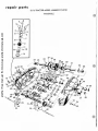
SS/16 TRACTOR--MODEL NUMBER 917.25752
ONAN ENGINE MODEL NUMBER BF-MS2666C
29
another free manual from www.searstractormanuals.com
~6
·~-9
26
~~-'O
25
33
CYLINDER BLOCK GROUP
4824R·15.2.74
- 27 -
•
repair
parts
55/16 TRACTOR--MODEL NUMBER 917.25752
ONAN ENGINE MODEL NUMBER BF-M52666C
REF. NO.
1
2
3
another free manual from www.searstractormanuals.com
4
5
6
7
8
9
10
11
12
13
14
15
16
17
18
19
20
21
22
23
24
25
26
27
28
29
30
31
32
33
34
35
36
37
38
39
40
41
42
43
44
45
PART
Cylinder Block Group
PART DESCRIPTION
NO.
Cylinder Block Assembly
11 0-1943
123-1174
Spring
123-117 5
Valve
Boffle
123-1173
Flat Washer (~" Steel)
526-0018
Flat Washer (~" Copper)
526-0063
Flat Washer (5/16" Steel)
526-0122
Cover (L.H.)
11 0-1878
Cover (R.H.)
110-1879
Gasket
110-1921
*Expansion Plug
517-0048
Stud (5/16" x 2-5;16")
520-0424
Stud (5116" x 2- 1/16")
520-0759
Stud (~" x 2-1/16")
520-0757
*Shim (.005")
104-0776
110-1920
Gasket
110-1924
Cylinder Head (R.H.)
Cylinder Head (L.H.)
110-1925
*Hex Cap Screw (3;$-16 x 1~")
800-0051
Breather Tube
123-1176
REAR BEARING KIT
101-0420
*Standard
101-0420-02
.002" Undersize
104-0575
*Bearing Thrust Washer
101-0415
*Gasket
101-0407
*Bearing Plate (Less Bearing)
101-0367
*Camshaft Bearing (Precision)
509-0041
*Oil Seal
516-0072
*Stop Pin
110-0445
Hex Nut (5116-24)
866-0001
Acorn Nut (~-20)
110-0893
Retainer
115-0006
Tappet
850-0050
*Lock Washer (3;$")
120-0706
*Oi I Tube
110-1808
Intake Valve
Exhaust Valve
110-1809
EXHAUST VALVE SEAT INSERT
110-0245
Standard
11 0-0245-02
.002" Overs i ze
INTAKE VALVE SEAT INSERT
*Standard
110-0197
110-0197-02
.002" Oversize
11 0-1935
*Va Ive Guide
110-0539
Va Ive Spring
110-0639
Retaining Lock
FRONT BEARING KIT
101-0432
*Standard
101-0432-02
.002" Unders i ze
806-0027
Hex Head Cap' Screw (3;$-16 x %")
526-0066
Flat Washer (3;$" Copper)
110-0068
Gasket (Used with Intake Valve Guide Only)
520-0820
Stud (3;$-16)
*-Included in Cylinder Block Assembly.
-Use one only with rear bearing on units with flange type front bearing.
4824R-15.2.74
- 28 -
•
repa I r pa rts
another free manual from www.searstractormanuals.com
SS / 16 TRACTOR •• MODEL NUMBER 917.25752
ONAN ENGINE MODEL NUMBER BF-MS2666C
25
16
27
CRANKSHAFT, FLYWHEEL, CAMSHAFT
AND PISTON GROUP
4824R· 15.2.7 4
• 29 -
1 4 - - 12
•
repair
parts
55/16 TRACTOR--MODEL NUMBER 917.25752
ONAN ENGINE MODEL NUMBER BF-M52666C
another free manual from www.searstractormanuals.com
Crankshaft, Flywheel, Camshaft and Piston
Group
REF. NO.
1
2
3
4
5
6
7
8
9
10
11
12
13
14
15
16
17
18
19
20
21
22
23
24
25
26
27
28
4824R-l. 3.74
PART DESCRIPTION
PART NO.
150-0078
150-0612
510-0015
104-0779
134-2432
Snap Ring
Governor Cup
Fly Ball
Ring Gear
Flywheel Assembly {Includes
Ring Gear & Rotor)
Timing Gear Set (Includes
105-0353
Camshaft a nd Crankshaft Gears)
105-0004
Thrust Washer
515-0001
Woodruff Key (1;8" )( 1;2")
515-0002
Woodruff Key (3/16" x 3/4")
105-0388
Camshaft and Center Pin Assembly
150-0075
Center Pin
PISTON AND PIN (Includes Retaining Rings)
112-0134
Standard
112-0123-05
.005" Overs i ze
112-0123-10
.010" Oversize
112-0123-20
.020" Oversize
112-0123-30
.030" Oversize
112-0123-40
.040" Oversize
PISTON PIN
112-0122
Standard
.002" Oversize
112-0122-02
Retaining Ring
518-0311
114-0225
Rod Assembly
RING SET
Standard
113-0174
.005" Overs i ze
113-0159-05
.010" Overs i ze
113-0159-10
.020" Oversize
113-0159-20
.030" Oversize
113-0159-30
113-0159-40
.040" Oversize
Bolt (Special)
114-0228
Flat Wa sher (Spec ia I)
526-0017
870-0277
Locking Nut (5/16-24)
Lock Washer (7/16")
850-0055
134-2384
Guard
Hex Head Cap Screw (7/16-14 x 4")
104-0170
Key (Y.;" x W' x 2")
515-0103
518-0014
Retaining Ring
104-0043
Washer
104-0763
Crankshaft
Locking Screw (y';-20 x Y2")
821-0010
Locking S&rew (5/16-18 x Y2")
821-0014
- 30 -
•
rep a I r par t 5
SS / 16 TRACTOR--MODEL NUMBER 917.25752
ONAN ENGINE MODEL NUMBER BF-MS2666C
3
10
\
another free manual from www.searstractormanuals.com
31
17-~
26 ---@)
9
16--_g
.~
IS-.g
33""'O~
24
GEAR COVER, OIL BASE AND
OIL PUMP GROUP
AQ")AO.'<; ')7.1
_ 1 1.
29-30
•
repair
parts
55/16 TRACTOR--MODEL NUMBER 917.25752
ONAN ENGINE MODEL NUMBER BF-M52666C
Gear Cover, Oil Base and Oil Pump Group
REF. NO.
another free manual from www.searstractormanuals.com
1
2
3
4
5
6
7
8
9
10
PART NO.
12
13
14
15
16
17
18
19
20
21
22
23
24
25
26
103-0396
510-0105
150-1349
150-1187
815-0046
516-0130
509-0008
510-0014
509-0040
103-0408
516-0011
123-1138
102-0693
505-0056
102-0741
120-0140
801-0050
120-0398
120-0491
120-0413
505-0002
505-0158
122-0359
122-0321
526-0065
526-0066
27
28
29
30
31
32
33
34
800-0028
800-0056
800-0032
800-0034
800-0007
850-0050
850-0045
850-0040
11
PART DESCRI PTION
Gear Cover As semb Iy
*Bearing (Upper)
*Shaft and Arm As semb Iy
*Yoke
"Screw (8-32 x 3;$")
"'Pin (3116" x 7;$")
""Oil Seal
*Bearing
*Seal
Gasket
Pin (5/16" x l-lA3")
Cap and Indicator
Gasket
Pipe Plug ();2")
Oi I Base
Spring (Oil By-Pass)
Hex Head Screw (3/$-24 xl")
Valve (Oi I By-Pass)
Oi I Pump Assembly (Complete)
Intake Assembly
Pipe Nipple ();2" x 3")
Pipe Cap ();2")
Cover
Gasket
Flat Washer (5116" Copper)
Flat Washer (3;$" Copper)
(Oi I By-Pass)
Hex Head Cap Screw (5116-18 xl")
Hex Head Cap Screw (3;$-16 x 2);2")
Hex Head Cap Screw (5116-18 x Hf')
Hex Head Cap Screw (5/16-18 x 2W')
Hex Head Cap Screw (~-20 xl")
Lock Washer (3;$")
Lock Washer (5116")
Lock Washer (~")
*-Included in Gear Cover Assembly.
4824R-l.3.74
- 32 -
•
rep a I r part s
SS/16 TRACTOR--MODEL NUMBER 917.25752
ONAN ENGINE MODEL NUMBER BF-MS2666C
another free manual from www.searstractormanuals.com
r:::rp--15
1!il!]j(1J--- 1 3
2
16~
FUEL SYSTEM GROUP
AQ'1AD_l t;.?
.74
- 33 -
5
•
repa.r
parts
SS/16 TRACTOR--MODEL NUMBER 917.25752
I
ONAN ENGINE MODEL NUMBER BF-MS 2666C
Fuel System Group
REF. NO.
1
2
another free manual from www.searstractormanuals.com
3
4
5
6
7
8
9
10
11
12
13
14
15
16
17
18
19
20
21
22
23
24
25
26
27
28
4824R·15.2.74
PART DESCRIPTION
PART NO.
~
Air Intake Tube
Carburetor Assembly (Complete)
Gasket
Intake Manifold
Gasket
Stud (5116-18 x 212")
Support
Hex Nut (5116·18)
Vacuum Tube
Vacuum Hose
Gasket
Housing
Element
Cover
Wing Nut (~·20)
Half Nipple (1" x 3")
Hex Head Cap Screw (~·20 x 1W')
Lock Washer (~")
Lock Washer (5116")
Round Head Screw (10·32 x 3A3")
Pre·Cleaner
Support Spring
Cap
Clip
Lifting Bracket
Hex Head Cap Screw (~·20 x Y2' ')
Hex Nut (~-20)
Lock Wa sher (~")
~
154·1468
154-1446
520-0758
140-1198
862·0015
149-1299
503·0644
140-1215
140-1213
140-1216
140-1168
865-0019
505·0755
800·0008
850-0040
850·0045
815·0377
140-1218
149-1308
149-1321
518·0328
403·1021
800·0003
862·0001
853-0013
- 34 -
ra p air part 5
SS/16 TRACTOR--MODEL NUMBER 917.25752
ONAN ENGINE MODEL NUMBER BF-MS2666C
another free manual from www.searstractormanuals.com
~'0
2
14
12
27
25
22
11
~/
o
18
CARBURETOR PARTS GROUP
- '< <; -
~4
3
repair parts
SS/16 TRACTOR--MODEL NUMBER 917.25752
I
ON AN ENGINE MODEL NUMBER BF-MS2666C
Carburetor Parts Group
REF. NO.
1
another free manual from www.searstractormanuals.com
2
3
4
5
6
7
8
9
10
$
15
16
17
18
19
20
21
22
23
24
25
26
27
"~'4
PART NO.
PART DESCRIPTION
142-0532
142-0523
142-0534
142-0535
142-0536
~
ro t e
Screw
*Screw
Screw
Screw
Gasket
Gasket
Gasket
*Diaphragm
Spring
*Spring
*Spring
Choke Fly
Float and Lever Assembly
*Float Lever Shaft
*Idle Needle
Power Needle Assembly
O-Ring
tover
*PJcHe
r-*FJow-VoJyeAssembIYi
I.---CI ip
,
*Gasket Set {Includes 142-535 Packing}
Repair Kit
142-0064
142-0334
142-0539
142-0540
142-0541
142-0542
142-0543
142-0535
142-0544
142-0282
142-0545
142-0546
142-0547
142-0548
142-0016
142-0549
142-0550
142-0551
142-0552
142-0553
142-0554
142-0556
142-0557
/l.(Z--~7
*-Included in Repair Kit
4824R-15.2.74
f31.e//l,
- 36 -
•
ra p a I r part s
SS/16 TRACTOR •• MODEL NUMBER 917.25752
another free manual from www.searstractormanuals.com
ONAN ENGINE MODEL NUMBER BF-MS2666C
10
9
-
~:~~~~~) J
pl~
30
GOVERNOR, STARTER, CHARGING ALTERNATOR
AND BLOWER HOUSING GROUP
4824R· 15.2.74
• 37 •
•
repair
parts
SS/16 TRACTOR--MODEL NUMBER 917.25752
DONAN ENGINE MODEL NUMBER BF-MS2666C
another free manual from www.searstractormanuals.com
Governor, Starter, Charging Alternator and
Blower Housing Group
PART NO.
PART DESCRIPTION
1
2
3
4
5
6
7
150-1350
518-0004
870-0278
134-2382
134-2393
134-2383
191-0933
8
9
10
11
12
13
14
15
16
17
18
19
20
21
22
23
24
25
26
27
28
29
30
191-0885
150-1345
150-1343
142-0035
152-0155
516-0059
518-0176
150-1269
150-1214
813-0108
812-0066
815-0104
850-0040
850-0030
850-0045
800-0028
821-0010
526-0006
526-0214
526-0113
815-0261
134-2606
815-0378
Control Rod
Clip
Push Nut (3/16")
Cylinder Air Housing (L.H.)
Blower Housing
Cylinder Air Housing (R.H.)
Starting Motor Assembly (For
Compenents See Separate Group)
Charg i ng A Iternator Starter
Arm
Bracket
Spring
Swivel
Cotter Pin
Clip
Bushing
Spring
Round Head Screw (10-32 x 1W')
Round Head Screw (6-32 x 14' ')
Round Head Screw (8-32 x 5/16")
Lock Washer Of')
Lock Wa sher (#10)
Lock Washer (5/16")
Hex Head Cap Screw (5/16-18 xl")
Hex Head
Screw (~-20 x W')
Flat Wa sher #12)
Flat Washer (~")
Flat Washer (5/16")
Hex Head Cap Screw (~-20 x 7/16' ')
Screen Guard (Stationary)
Self Tapping Screw (#14 x W')
REF. NO.
I
4824R-15.2.74
CaU
- 38 -
•
repair
parts
SS/16 TRACTOR--MODEL NUMBER 917.25752
another free manual from www.searstractormanuals.com
ONAN ENGINE MODEL NUMBER BF-MS2666C
6
18-19
4
5
19-20
13
11
~15
IGNITION GROUP
4824R-15.2.74
• 39 •
•
repair
parts
SS/16 TRACTOR-MODEL NUMBER 917.25752
ONAN ENGINE MODEL NUMBER BF-MS2666C
Ignition Group
another free manual from www.searstractormanuals.com
REF. NO.
1
2
3
4
5
6
7
8
9
10
11
12
13
14
15
16
17
18
19
20
PART NO.
PART DESCRIPTION
Breaker Box Assembly
*Gasket
Clamp
*Point Set
*Flat Washer (#8)
*Condenser
Clip
Gasket
*Cover
Plunger
Cable (21 ")
Coil
Cable (19")
*Pan Head Screw (8-32 x 3;8' ')
Spark Plug
*Lead Assembly
Screw (!;.i.20 x 5;8")
Lock Washer (!;.i")
*Lock Washer (#8)
*Pan Head Screw (8-32 x 3;8")
160·1158
160·1148
503·0365
160·1154
526·0003
312·0069
167·0188
160·1150
160·1149
160·1151
167·1548
166-0535
167·1463
815·0358
167-0241
336·2132
802-0034
850-0034
850-0025
815-0358
*·Included in Breaker Box Assembly.
4824R-15.2.74
- 40 -
•
(e p a I r par t 5
SS / 16 TRACTOR--MODEL NUMBER 917.25752
ON AN ENGINE MODEL NUMBER BF-MS2666C
Starter Parts Group
0
another free manual from www.searstractormanuals.com
123456
11
d~Jo1o~~o
I
I
r
.....;...----
-
-
....., . - - - , . - - - -
J
I
!!!P'"un;w' @
- -
-
....
~---
12-~_13
14-~_15
16_~
I
1
!
10
9
-
....~~-- -
22
~17
~,
~~
, iL
19
\( [
20_~
21 ----::::-.,
\~
'>:
23---
REF. NO.
1
2
3
4
5
6
7
8
9
10
11
12 thru 21
22
PART NO.
191-1034
191·1045
191·1046
191·1035
191·1047
191·1036
191·1037
191·1038
191·1048
850·0040
191·1039
Not Sold Separately
Order #22 191·1040
191·1040
QTY . USED
1
1
1
1
1
1
1
1
2
2
1
AA?L1R. 1.':;.2.74
Cover, Dust
Nut, Stop
Washer, Stop Nut
Spring, Anti·Drift
Spacer, Dust Cover
Drive Assembly
Cap Assembly, Drive End
Washer, Armature Thrust
Screw, Hex Cap· Through
Starter
Washer, Lock
Armature
Cap Assembly (Includes
Key #12 thru 21)
Kit, Brush, Spring & Stud
(Key #17, 18 & 20)
191·1041
23
PART DESCRIPTION
Not Sold Separately
Order
191.0933
Starting Motor Complete
• 41 •
~--------------------------------------The Model Number will be found on 0 plate ottached to the rear
of the Chassis Channel and to the front of the seat. Always men·
tion the Model Number when requesting service or repair part!
for your Garden T Tactor.
'.
All parts listed herein may be ordered through SEARS, ROEBUCK
another free manual from www.searstractormanuals.com
[Sears I
owners
manual
AND . CO. or SIMPSONS-SEARS LIMITED. When ord~ring parts by
mail, selling prices will be furnished on request or\,?arts willbe
shipped at prevailing prices and will be billed
WHEN ORDERING REPAIR PARTS, ALWAYS GIVE TH5-: FOLLOWING INFORMATION AS SHOWN IN THIS LIST.
3. The MODEL NUMI ~ER
917.25752
1. The
PART
NUMBER
2.
PART
DESCRIPTION
The
J .
MODEL NO.
91Z 25752
How to Order
Repair Parts
SEARS SERVICE
IS AT YOUR SERVICE
WHEREVER YOU LIVE
OR MOVE
IN THE U.S.A.
" ~
accordin~~.r·
4.
The
NAME
OF ITE 'M-
Garden Tractor
When you buy merchandise
from Sears you get an extra
something that nobody else
can offer ••• Sears Service.
'.
Across town or across the
country, wherever you live
or move in the U.S.A., Sears
Service follows you, providing trustworthy, competent ..
service
technicians IJsi ,
only Sears specil":', their
t
i'ldangered,
L -__~____~___________________________ _
par s.
.lgIOe of your
.t lever is in
lttachments is
~e foot brake
'g brake. Tile
ngaged when
.'e tractor is
Your new Tractor is used to provide po.;,ged serious
operating or pulling a large variety of m<'tor's seat,
attachments. The air cooled engine tran1t achments
power to the rear wheels. The transmissioi engag~d,
geared to provide all the trave~ speeds requi: ;:~;~:
for those attachments. Use the same care and tgn ition
tentiveness when operating your tractor as yo(ator's
' ,
'ment
wou Id
when d riving
your automo b'l
I e.
{rom
;k
Revision
4824R-l.3.74
Sears, Roebuck and Co" Chicago, Ill. 60684
and Simpsons Sears Limited, Toronto
.---------------------------------------------
another free manual from www.searstractormanuals.com