1
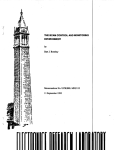
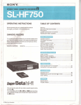
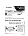
SFECIFICRTIONS
0
0
0
0
0
0
0
0
0
0
0
0
0
0
Class AB Circuitry
Tri-Mode Capable
High Level Input
Low Level Input
RCA Line Output
35-250Hz Variable Low Pass Filter
35-250Hz Variable High Pass Filter
0-12dB Variable Bass Boost
0-180 Variable Phase Shift
15-30Hz Variable Subsonic Filter (V5011)
0.05%THD
S/N>85dB
Thermal, Short, Overload Protection
2OOmV-8V RCA Input
2 Ohm Stereo, 4 Ohm Mono Stable
Remote Bass Control (except V3209)
Built-in Cooling Fans (except V3209)
MODEL
Total Peak Power
RMS Pwr per CH @ 4 Ohm
RMS Pwr per CH @ 2 Ohm
RMS Pwr Mono @ 4 Ohm
THD @ 4 Ohm
@ 2 Ohm
SM Ratio
Channel Separation
Frequency Response+OSdB
Crossover Frequency LPF
Crossover Frequency HPF
Bass Boost
Low Level Input Range
High Level Input Range
Low Level Impedance
High Level Impedance
Fuse
Dimensions(H x W x L)
I
I
V3209
300W
75W
IOOW
175w
1
I
V3309
500W
125W
175w
300W
I
I
-
t
1
~
1
j
1
V3909
1600W
300W
400W
SOOW
j
V
s
i
1OOO\V
'
500W
700W
13OOM
1
!
THD@4Ohni
@ 2 Ohm
SM Ratio
~
I
Crossover Frequency LPF
' BassBoost
I
~
Low Level Input Range
High Level Input-7ange
Low Level Impedance
20Ampxl
30Ampxl
2"x11
518" x 7314"
2"x11
518" x 9314"
3118"Xll
518" x 11112"
I
1
V3509
8OOW
200w
250W
500W
1
I
V3709
1200w
300W
400W
800W
7
!
I
I
High Level Impedance
I FIIW
V3409
600W
150W
200w
400W
0.05%
<O.l%
>90dB
60dB
20Hz-30kHz
35Hz-250Hz
35Hz-250Hz
0-12dB
200mV-8V
3-1OV
10k Ohms
100 Ohms
20Ampx2
-2-
MODEL
Total P e a k p o w e r
RMSPwrperCH@4Ohm
RMS PwrperCH@ZOhni
RMS PwrMono @ 4 Ohnil
~
I
40Amux3
1
25 Anir
COI*(I*(ECTIONS
Each input and output jack is individi
errors. Male to male RCA cables are reqi
inputs to the source units or crossover ou
should be used to minimize the pickup 0:
should be run on the opposite side of the
wires of the Amplifiers. This will help to
Before making any electrical connection.
Ground cable to prevent the possibility o
electronic equipment.
25Ampx2
30Anipx3
2"x11
518" x 131/2"
2" x 11
518" x 17314"
1
-3-
1
1
1
MODEL
Total Peak Power
RMSPwrperCH@4Ohm
RMSPwrperCH@2Ohm
RMSPwrMono@4OhniI
V3909
' V4309
,16oow/1ooo\v
'
I
300W
400W
800W
1
40Anipx3
1
I
~
'
500W
700W
1300W
V5011
lOOOW
300W
N-A
SOOW
V6611
2 x 200w + 1 x soow
4 x 7 5 W + 2 x 175W
4 x lOOW+2x25OW
2~150W+1x4OOW
I
___j
1
1
'
~
1
ter
ter
r (V5011)
tion
ble
1209)
3209)
V3309
5oow
125W
175W
300W
Fuse
Dimensions(H x W x L)
I
I
V3409
600W
15ow
200w
400W
I
1
V3509
8OOW
200w
250W
5oow
I
I
V3709
1200w
300W
400W
8OOW
J
2 " x 11
518" X 9314"
-2-
I
311s"~11
518" X
11 112"
I
I
2 " x 11
518" X 13112"
I :;;':
518
2'':
20 Amp x 3
25 A m p x 2 40Ampx 1
1 2 " x 11
2"x 11
X21112" 518"X 15112" 518"X 13112''
2"
I 1 ~ 1 8 " 2 I 112"
~
CONNECTIONS
Each input and output jack is individually labeled to reduce installation
errors. Male to male RCA cables are required to connect the AMPLIFIER
inputs to the source units or crossover outputs. High Quality shielded cables
should be used to minimize the pickup of electrical noises. The RCA cables
should be run on the opposite side of the vehicle from the power and ground
wires of the Amplifiers. This will help to minimize noise problems.
>90dB
60dB
20Hz-30!&z
35Hz-250Hz
35Hz-250Hz
0-12dB
200mV-8V
3-1OV
Ink Ohms
100 Ohms
i
~
Before making any electrical connections, Disconnect your car battery's
Ground cable to prevent the possibility of short circuits or damage to your
electronic equipment.
h314"
-3-
I
1
I
I
Model: V6611
@ @ @ @ @
0 0 0
I)EMarE
E
6
'
Model: V5011
4-
6
8 c
, . . . .,.
.
. ..
-
..
-. .
~.- - ~
i
~
.
-
~
2.
3.
4.
5.
6.
7.
8.
9.
10.
11.
12.
13.
14.
15.
16.
Speaker Terminals
Connects the speakers to the amplifier
Input Sensitivity Controls
Varies the input voltage to the amplifier
Low Level RCA Inputs
Connects the RCA terminals from a source unit
RCA Line Output
Used for connecting multiple amplifiers
High Level Inputs
Used for when RCA low level jacks are not available
Crossover Selection Switch
Selects the crossover mode
Ground Connection
Connects to the vehicles chassis
Positive 12V Connection
Connects to the vehicles battery
Remote Turn-on Connection
Connects to the remote turn-on lead of the source unit
35-250Hz Variable Low Pass Filter
Allows frequencies below the set level to pass when the
crossover is in LPF mode
35-250Hz Variable High Pass Filter
Allows frequencies above the set level to pass when the
crossover is in HPF mode
0-180"Variable Phase Control
Used when in LPF mode, to adjust the phase of the subwoofers
0-12dB Variable Bass Boost
The control adjusts the Bass Boost Gain for the amplifier's
speaker output.
15-250Hz Variable Subsonic Filter
Used when in LPF mode, to adjust the frequencies sent to the
output of the amplifier to the subwoofers
LED Indicator
Lit Green when the amplifier is working properly
Lit Red when in Protection Mode
Remote Bass Control Connection
Used to control the gain of the output of the amplifier (Figl)
_-- - - - - - - - - -
I
.
17.
....
AMPLIFIER SETUP
CONTROLS
1.
__.....
._
.
-6-
>
To adjust, proceed as follows:
a. Set INPUT LEVEL controls at mid-po
b. Listen for audible distortion as you inc
control. If no distortion is heard, turn tl
"MAX" in small stages until the onset
decrease to the level prior to the immei
c. If distortion is immediately heard, turn
clear.
POWER INPICSTOR LED
This GREEN LED will illuminate whene
it fails to illuminate, check the power co
PROTECTION CIRCUIT
Should the Amplifier become shorted, o\
protection circuit will "SHUT-DOWN"
turn "RED" . The amplifier will remain ii
caused the problem is corrected. To reset
"OFF" ,and then turn "ON" again.
CAUTI
THIS AMPLIFIER IS DESIGNED TO O>
IMPEDANCE OF 2 OHMS IN STEREO.
Ohms IN MULTI-MODE (TH-MODE)
THE AMPLIFIER TO IMPEDANCES L(
MAY CONSTITUTE TO POTENTIAL Di
IS NOT COVERED UNDER WARRANT
-
---------Input Mode Switch
Used to select which input is used to drive the amplifier.
k
\
INPUT SENSITIVITY (LEVEL) CON
In order to achieve maximum signal-to-nc
adjust the signal level from your source u
sensitivity. It is NOT a volume control. T
control by the external remote controller.
- I
-1-
INPUT SENSITIVITY (LEVEL) CONTROLS
In order to achieve maximum signal-to-noiseperformance, these controls
adjust the signal level from your source unit, to match the Amplifier's
sensitivity. It is NOT a volume control. This input sensitivity can also can be
control by the external remote controller.
e amplifier
:he amplifier
1s from a source unit
To adjust, proceed as follows:
a. Set INPUT LEVEL controls at mid-point.
Ile amplifiers
b. Listen for audible distortion as you increase the Head Unit VOLUME
control. If no distortion is heard, turn the adjustment level control toward
"MAX" in small stages until the onset of audible distortion is heard, then
decrease to the level prior to the immediate point of audible distortion.
vel jacks are not available
assis
c. If distortion is immediately heard, turn control to MIN" until the sound is
clear.
.ttery
1-on lead of the source unit
s Filter
:he set level to pass when the
POWER INDICATORLED
This GREEN LED will illuminate whenever the Amplifier is turned "ON" . If
it fails to illuminate, check the power connections to the Amplifier and fuses.
is Filter
:he set level to pass when the
PROTECTION CIRCUIT
-01
Q
Should the Amplifier become shorted, overloaded or overheated, the
protection circuit will "SHUT-DOWN" the Amplifier and the Power LED will
turn "RED" . The amplifier will remain inoperable until the condition that has
caused the problem is corrected. To reset the amplifier, turn your amplifier
"OFF" , and then turn "ON" again.
adjust the phase of the subwoofers
,s Boost Gain for the amplifier's
:Filter
o adjust the frequencies sent to the
ie subwoofers
ier is working properly
i Mode
cction
the output of the amplifier (Figl)
c-
<
CAUTION:
THIS AMPLIFIER IS DESIGNED TO OPERATE WITH A MINIMUM LOAD
IMPEDANCE OF 2 OHMS IN STEREO. 4 OHMS MONO (BRIDGED). OR 8
Ohms IN MULTI-MODE (TRI-MODE) CONFIGURATIONS. SUBJECTING
THE AMPLIFIER TO IMPEDANCES LOWER THAN RECOMMENDED,
MAY CONSTITUTE TO POTENTIAL DAMAGE TO THE AMPLIFIER.AND
IS NOT COVERED UNDER WARRANTY
----------.
- - - - - - - - - - -'
is used to drive the amplifier.
-6-
-1-
, .
-
~
. .
-. ..
.--
- __..~
.
.
~
.
..
-
.
.. .
I
. .
..
.
. . .
If you plan to expand your system by adding other components
sometime in the future, ensure adequate space is left.
NOTE.
Consider both the length of your leads, and routing when
determining the mounting location. Pre-Amp RCA input jacks
require high quality shielded male to male RCA patch cord.
1. Always use high quality RCA type shi
2. Always use the shortest length possibl
"S" shape loop (not a coiled loop) to 1
3. Never cut the shielded cable and re-sp
4. Never route any Amplifier input cable
ignition wires, or near computer contrc
MOUNTING YOUR SYSTEM
The mounting position of your Amplifier will have a great effect on its
ability to dissipate the heat generated during normal operation. The Amplifier
has an efficient heat sink for proper heat dissipation, also integrated with a
thermal shutdown (for heat protection) circuit. Allowing air around the
cooling fins will improve heat dissipation dramatically. DO NOT enclose the
amplifier in a small box or cover it so that air cannot flow around the cooling
fins.
Temperatures in car trunks have been measured as high as (158' F) in the
summer time. Since the thermal shut-down point for the Amplifier is (160' F)
it must be mounted for maximum cooling. To achieve maximum convection
air flow in an enclosed trunk, mount the amplifier in a vertical position, on a
vertical surface.
Cooling requirements are considerably relaxed when mounting inside the
passenger compartment since the driver will not often allow temperatures to
reach a critical point. Floor mounting under the seat is usually satisfactory as
long as there is at least 1 inch above the Amplifier's fins for ventilation.
To mount the Amplifier:
1. Use the amplifier as a template to mark the mounting holes.
2. Use extreme caution, inspect underneath surface before drilling.
3 . Remove the Amplifier and drill the marked holes.
4. Secure the Amplifier using the screws provided.
-8-
DO NOT USE THESE RCA JACKS IN CONJUNC
J
To 0
Of Hea
STEM
lour system by adding other components
NOTE.
, ensure adequate space is left.
DO NOT USE THESE RCA .JACKS IN CONJUNCTION WITH HIGH LEVEL INPUT WIRES.
1. Always use high quality RCA type shielded cables.
2. Always use the shortest length possible. If the cable is too long, make on
"S" shape loop (not a coiled loop) to take up any excess.
3. Never cut the shielded cable and re-splice it.
4. Never route any Amplifier input cables near speaker outputs, high energy
ignition wires, or near computer controlled ignition circuit units.
h of your leads, and routing when
ng location. Pre-Amp RCA input jacks
elded male to male RCA patch cord.
(STEM
Amplifier will have a great effect on its
1 during normal operation. The Amplifier
heat dissipation, also integrated with a
In) circuit. Allowing air around the
lation dramatically. DO NOT enclose the
o that air cannot flow around the cooling
re been measured as high as (158' F) in the
.-down point for the Amplifier is (160' F)
oling. To achieve maximum convection
the amplifier in a vertical position, on a
1'
r
I
0
0 0
E-E
To Outputs
Of Head Unit
ii
~ ~ T o I n p " t
Additional Amplifiers
iderably relaxed when mounting inside the
ver will not often allow temperatures to
g under the seat is usually satisfactory as
the Amplifier's fins for ventilation.
'late to mark the mounting holes.
ct underneath surface before drilling.
drill the marked holes.
the screws provided.
To Outputs
OfHead Unit
-8-
-9-
To Outputs
Of Head Unit
To Input
Additional Amplificrs
To Outputs
Of Head Unit
H1GI-l LEVEL INPUT CONNECTIONS
NOTE.
DO NOT CONNECT THESE HIGH LEVEL INPUT WIRES IF YOU ARE USING THE LOW
LEVEL INPUTRCA JACKS
Model: V6611
Model: V5011 I V3209 I V3309 I V3409 I V3509 I V3109 I V3909
(Input Mode Switch: 4Ch)
I CHANN
I
\
I
J
SPEAKER TERM1
I'
RIGHT CHANNEL
- (Brown)
I
RIGHT CHANNEL + (Gray)
Model: V4309
1 CHANNEL + Nvhite)
4 CHANNEL +(white)
I r o n HEADUNIT
4 CHANNEL- (Green)
CHASSIS GROUND (Black)
3 CHANNEL - (Brown)
3 CHANNEL + (Gray)
-10
-11-
00
3 0
cc00
_i
P
I
_... . .. . -
SPESYER CONNECTION!
1 Channel Amplifier
2 Channel Amplifier
Model: V5011
Model: V3209 I V3309 I V3409 I V3509 I
Bridged M
SUBWOOFER
4-8 OHMS
To REMOTE OUTPUT
of HEAD UNlT
2-8 OHMS
2 Channel Amplifier
2 Channel Amplifier
Model: v3209 I V3309 I V3409 I V3509 I
Tri-Stereo T
Model: V3209 I V3309 I V3409 I V3509 I V3709 I V3909
Stereo Mode
3
KlGHT SPEAKEK
2-8 OHMS
CROIJND
RIGHT SPFAKEK
4-8 OHMS
To REMOTE OUTPUT
LECT SPEAKER
2-8 OHMS
oSHEAD UNIT
-12-
a
+
LEFTSPEAK
4-8OHMl
BRIDGED
4-8 OHMS
-13-
2 Channel Amplifier
Model: V3209 I V3309 I V3409 I V3509 I V3709 I V3909
Bridged Mode
rl
I
3
).
@ ToBAlTERY
%
GROUND
To REMOTE OUTPUT
SUBWOOFER
4-8 OHMS
O f H E A D UNIT
To REMOTE OUTPUT
of HEAD UNlT
V3509 I V3709 I V3909
:re0 Mode
2 Channel Amplifier
Model: V3209 I V3309 I V3409 I V3509 I V3709 I V3909
Tri-Stereo Mode
KIGHT SPEAKEK
4-8OHMS
*+
u
LEFTSPEAKER
4-80HMS
UKIDGED
4-8 OHMS
-12-
-13-
SpEqyEq CONNECTIONS
SPEAKER CONNECTIOI*(
4 Channel Amplifier
4 Channel Amplifier
Model: V4309
Model: V4309
Tri-Stereo
of HEAD UNIT
CH3 SPEAKER
2-8 OHMS
2 Channel Amplifier
Model: V4309
CH112 BRIDGED
4-8 OHMS
CHZSPEAKER
4-8 OHMS
\ /
a+
CH1/2 BRIDGED
4-8 OHMS
CH3/4 BRIDGED
of HE AD UNlT
-14-
-1 5 -
t
I
L
I
ocoo
d,
n
2
2
0
L
r
n
r e
N S
N0
S
'
N3
n
4
n
VI
5
z
1
m
z
8z
n
m
X
D
m
VI
71
1
SPEA6ER COl*Il*IECTlOl*IS
.lOl*lS
6 Channel Amplifier
Model: V6611
Tri-Stereo Mode
Ch3 SPEAKER
4-8 OHMS
Ch4 SPEAKER
4-8 OHMS
Ch5 SPEAKER
4-8 OHMS
-id
+
Chl SPEAKER
2-8 OHMS
-
'g
Tfi
GROUND
Ch6 SPEAKER
4-8 OHMS
Ch2 SPEAKER
2-8 OHMS
I
ofHIiAD UNIT
Ch3 SPEAKER
2-8 OHMS
+
ged Mode
?-
-2
CH5/6 BRIDGED
4-8 OHMS
CH1/2 BRIDGED
4-8 OHMS
+
- =+
-To REMOTE OUTPUT
CH3/4 BRIDGED
4-8 OHMS
@ ToBATI'ERY
CIi1/2 BRIDGED
4-8 OHMS
CROlJND
To REMOTE OUTPUT
of HEAD UNIT
-16-
ofHEAD UNIT
TROUBLE SHOOTlr*(G
TROUBLE SHOOTING
SYMPTOM
SYMPTOM
NOISE IN AUDIO SIGNAL (Whine)
NO SOUND
CHECK POINT
CHECK POINT
Is the power LED illuminated?
CURE
1. Check fuses in Amplifier.
2. Be sure Turn-on lead is connected
3. Check signal leads.
4. Check gain control.
5 . Check Tunerrneck volume level.
6 . Clean contacts on fuse holders.
If the noise is a whine whose p
Amplifier, Amplifier and any 4
grounded.
CURE
Inspect that Grour
(To v
met
CHECK POINT
SYMPTOM
AMPLIFIER NOT SWITCHING ON
Check the routing of the speal
to powers wires or interconnei
CURE
CHECK POINT
Re-Route RCA ca
No power to power wire
CURE
Repair power wire or connections
Note: If the above steps fail to improve or clear no
by a professional mob
CHECK POINT
No power to remote wire with Head Unit on
CURE
Check connections to Head Unit.
??Need More Techr
Please 1
www.VisonikC;
CHECK POINT
Fuse broken
CURE
Replace Fuse
SYMPTOM
NO SOUND IN ONE CHANNEL
CHECK POINT
Check Speaker Leads.
Check Head unit Balance Controls
CURE
Inspect for short circuit
Check for open Connection.
CURE
Check Speaker Leads Reverse Left and Right RCA inputs to
determine if it is occurring before the Amplifier.
-18-
-19.
G
TROUBLE SHOOTING
SYMPTOM
NOISE IN AUDIO SIGNAL (Whine)
CHECK POINT
minated?
uses in Amplifier.
Turn-on lead is connected
ignal leads.
Zain control.
runerrneck volume level.
ontacts on fuse holders.
If the noise is a whine whose pitch follows the engine speed, confirm that the
Amplifier, Amplifier and any other signal sources (head unit, etc.) are properly
grounded.
CURE
Inspect that Ground impedance are 0 ohms.
(To verify proper Ground impedance, use an OHM
meter to measure all equipment grounds.)
CHECK POINT
IG ON
Check the routing of the speaker and RCA cables to make sure they not adjacent
to powers wires or interconnect lights and other accessories.
CURE
Re-Route RCA cables and Wires
wer wire or connections.
fith Head Unit on
inections to Head Unit.
Note: If the above steps fail to improve or clear noise interference, the system should be checked
by a professional mobile audio installer.
??Need More Technical Support??
Please Visit
www.VisonikCarAudio.com
'use
Zontrols
rt circuit
1 Connection
.Leads Reverse Left and Right RCA inputs to
is occurring before the Amplifier.
-18-
-19-
0
Investigate the layout of your automobil
holes. Use extreme care when you work near
and electrical wiring. Always make sure the I
unit securely to the automobile will prevent d
particularly in the event of an accident.
LENGTHO F WARRANTY
1 year on Video Products
2 years on Electronic Products
2 years on Speakers
0 WHAT IS COVERED
Warranty applies only to Visonik products sold to consumers by Authorized Visonik
Dealers in the United States of America or its possessions. Products purchased by consumers
from Authorized Visonik Dealer outside of the USA are covered only by that country's distributor.
Don't mount the system so that the wire
to pinching or damage from nearby objects.
0 WHO I S COVERED
The +12 VDC power wire must be fuse(
connection. Before making or breaking powe
terminals, disconnect the + 12V wire at the bi
other equipment is turned off while connectir
terminals.
This warranty covers only the original purchaser of Visonik product purchased fiom an
Authorized Visonik Dealer in the United States. For a list of Authorized Internet Retail Stores go
In order to receive service, the purchaser must provide
to http://www.VisonikCarAudio.com.
Visonik with a copy of the receipt stating the customer name, Visonik Authorized dealer name,
product purchased and date of purchase. Products found to be defective during the warranty
period will be repaired / replaced (with a product deemed to be equivalent) at Visonik's discretion.
0
If you need to replace fuses, replace it o
with the system. Using a fuse of different typ
system which isn't covered by the warranty.
WHAT I S NOT COVERED
1. Damage caused by accident, abuse, improper operations, water, or theft.
2. Any cost or expense related to the removal or reinstallation of product.
3. Repair Service performed by anyone other than Visonik's Repair Department.
4. Any product which has had the serial number defaced, altered, or removed.
5. Any product purchased outside the United States.
6 . Any product not purchased from an Authorized Visonik Dealer.
.
0 LIMIT ON IMPLIED WARRANTIES
Any implied warranties including warranties of fitness for use and merchantability are limited
in duration to the period of the express warranty set forth above. Some states do not allow
limitations on the length of an implied warranty, so this limitation may not apply. No person is
authorized to assume for Visonik any other liability in connection with the sale of the product.
H O W TO OBTAIN SERVICE
1. Please call (3 10) 223-0400 for Visonik Customer Service.
Customer Service hours : Monday-Friday, 8am-5pm Pacific Standard Time.
2. Obtain a FL4 # (Return AuthorizationNumber) from Customer Service.
3. Obtain a "Cashiers Check" or "Money Order" for $9.00 per item for return postage.
(No personal Checks will be accepted)
4. Once you receive your return authorization number from our Warranty Department,
please print this number LARGE on the outside of the packaging.
5. No products will be accepted without a Return Authorization number.
6 . Please include the following items with the returned product:
a. Copy of the Original Receipt of purchase (Required)
b. Cashiers Check or Money Order for $9.00 per item
c. Return Address for shipment.
7. Ship to:
VISONIK
Warranty Department
3116 Via Mondo
Rancho Dominguez, CA 90221
,
RA#:
-20-
-2 1
r
WARCl(llr(6
lNFORMF(Tl0N
ectronic Products
Investigate the layout of your automobile thoroughly before drilling or cutting any
holes. Use extreme care when you work near the gas tanks, gas or hydraulic lines,
and electrical wiring. Always make sure the unit is securely mounted. Mounting the
unit securely to the automobile will prevent damage to the car or injury to a person,
particularly in the event of an accident.
2 years on Speakers
sold to consumers by Authorized Visonik
possessions. Products purchased by consumers
e USA are covered only by that country's distributor.
I
Don't mount the system so that the wire connections are unprotected or are subject
to pinching or damage from nearby objects.
The +12 VDC power wire must be fused at the battery positive terminal
connection. Before making or breaking power connections at the system power
terminals, disconnect the + 12V wire at the battery. Confirm your head unit and/or
other equipment is turned off while connecting the input RCA jacks and speaker
terminals.
irchaser of Visonik product purchased from an
For a list of Authorized Internet Retail Stores go
er to receive service, the purchaser must provide
customer name, Visonik Authorized dealer name,
'ducts found to be defective during the warranty
luct deemed to be equivalent) at Visonik's discretion.
2s.
If you need to replace fuses, replace it only with a fuse identical to that supplied
with the system. Using a fuse of different type or rating may result in damage to this
system which isn't covered by the warranty.
)er operations,water, or theft.
or reinstallation of product.
than Visonik's Repair Department.
,er defaced, altered, or removed.
States.
rized Visonik Dealer.
rlES
ties of fitness for use and merchantabilityare limited
inty set forth above. Some states do not allow
nty, so this limitation may not apply. No person is
ability in connection with the sale of the product.
nik Customer Service.
'riday, 8am-5pm Pacific Standard Time.
n Number) from Customer Service.
ey Order" for $9.00 per item for return postage.
ed)
ization number from our Warranty Department,
n the outside of the packaging.
ut a Return Authorizationnumber.
vith the returned product:
eipt of purchase (Required)
y Order for $9.00 per item
lent.
,
'ISONIK
ity Department
i Via Mondo
minguez, CA 90221
-20-
-21-
.............
.............................Fold andTea1 Here ............................
Class
Postage
VISONI k
^
Y
7
Y
C
I
Y
-
.
S
*
17621 S. Susana Road
Rancho Dominguez
CA
90221
Warranty applies only to Visonik products sold to
consumers by authorized Visonik dealers in the
United States of America or its possessions.
Products purchased by consumers from
authorized Visonik dealer outside of h e USA are
covered only by that country's distributor.
This warranb covers only lhe original purchaser of Visonik
produd purchased from an aulhorized Visonik dealer in h e
United S t a k Far a list of auhorized Internet retail stores go to
h t t p l / / w . visonikcaraudio.com. In order h receive sewice,
lhe purchaser must provide Visonik wilh a copy of h e receipt
staling h e customer name. Visonik aulhorized dealer name,
product purchasedand date of purchase. Produck found h be
defeciive during h e warranly periodwill be repaired or replaced
[wilh a product deemed to be equivalent1a t k o n i k discrelion.
I Odiiiilgp caJse0 bq accidenl. d h l i w improper
operahons.wdki r i i lnf4
2 An, rost oi expense rvl,il~rl10 Ihe iemova 0 1
reinsbllation of produc?
3 Repair service performed by anyone olher than
Visonik repair department
Any product Which has had the serial number
defaced, altered or removed.
5
productpurchased outside the United sbtes
6
product
purchasedfrom an
Visonik dealer.
w*.
,,
w.
Any implied wdiiantirs including wairantirs of fitness for
use and merchantabilitu are limited in duration to the
period of the express warranty set forth above. Some
states do not allow limitations on the length of an implied
warranty. so this limitation may not apply. No person is
authorized to assume for Visonik any other liability in
connection with the sale of h e product.
Fold andTear Here
This registration must be filled out and mailed within 10 days of purchase lo validate warranty.
Name >
Street >
L-
-
~~
~~
r~
~
p~
state
clty >
~p
r--
zip >
~
p~
Place Purchased
I
~
~
~
~
p~
Model Number >
>
-
1>
Date Purchased >
r-
~
p~
I
-
Purchased For > (CircleOnej > Gift > Replacement Speakers > Compehhon Use > Personal Use
If replacement, w h a l is the name and model number of the system replaced?
Name >
i
p
r-
-
~
Model Number >
~~
p~~
~~
-~
Why did y o u purchase Visonik speakers? > (C!rc/eOne) > Sound > Price > Dealer Recommendation
~~
> Other >
I
Additional Commenk >
-
-
~
p
Dear Customer,
Thank you for selecting Visonik for your high end mobile entertainment needs.
Visonik has many years of experience in the design and manufacturing of
mobile entertainment products.
Visonik has committed many years of research and development to
bring you products that will perform for your musical enjoyment.
Additionally, we are confident that your choice of Visonik will
bring you the satisfaction of great sounds so that when you
think about purchasing more mobile entertainment products
you will again select a Visonik product.
Please take a moment to complete the enclosed
customer survey card, this will enable us to keep
you advised on our latest advancements and
provide us a better understanding of our
customers. This information will also be used to
develop new products to meet your needs.
We appreciate the confidence demonstrated by your purchase of a
Visonik product and we shall do all
we
can to
uphold that
confidence.
Sincerely,
Sameer Aboabdo
President
Visonik Inc.
wwwvironlkraraudio corn
www visonikcaraudio corn
-
~
-~
-
ased Fram
e following magazines do you read? Circle any.
> AubSound &Securiiy > DUBMagazine > MAXPower
> Car Audio & Elec. > Other Magazines > [
rtainrnent
view
-
rstvisonik purchase? > Yes o i
No
-
~
~~~
brands do you normally buy? >
[
-
~-
~
did you consider before purchasing Visonik? >
~
-
-
~~
influenced your purchase? Circle any.
P'owerHandling > Appearance > Reputation > Friend > Other >
k equipment was inshiled by? > Yourself or Professional Installer
sonik purchase an upgrade for your exish'ng car stereo? >
Gender >
M
or
F
Yes or
Favorite MusicTuoe >
,
No
1
--