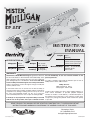
1
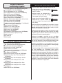
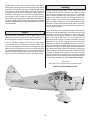
EP ARF
INSTRUCTION
MANUAL
®
Length:
SPECIFICATIONS
Radio:
Wingspan:
52.5 in
[1335mm]
Weight:
5.25– 5.75 lb
[2380– 2610 g]
Wing Area:
441 in2
[28.4 dm2]
Wing
Loading:
27– 30 oz/ft2
[82– 92 g /dm2]
Motor/ESC/Prop:
41.5 in
[1055mm]
4-5 Channel with
4 micro servos (w/o flaps) or
6 micro servos (with flaps)
RimFire™ .32 (42-50-800)
ElectriFly SS-45
APC-E 12x8
WARRANTY
Great Planes ® Model Manufacturing Co. guarantees this kit to
be free from defects in both material and workmanship at the
date of purchase. This warranty does not cover any component
parts damaged by use or modification. In no case shall Great
Planes’ liability exceed the original cost of the purchased kit.
Further, Great Planes reserves the right to change or modify this
warranty without notice.
this kit immediately in new and unused condition to the
place of purchase.
To make a warranty claim send the defective part or item to
Hobby Services at the address below:
Hobby Services
3002 N. Apollo Dr. Suite 1
Champaign IL 61822 USA
In that Great Planes has no control over the final assembly or
material used for final assembly, no liability shall be assumed nor
accepted for any damage resulting from the use by the user of Include a letter stating your name, return shipping address, as
the final user-assembled product. By the act of using the much contact information as possible (daytime telephone
number, fax number, e-mail address), a detailed description of
user-assembled product, the user accepts all resulting liability.
the problem and a photocopy of the purchase receipt. Upon
If the buyer is not prepared to accept the liability associated receipt of the package the problem will be evaluated as quickly
with the use of this product, the buyer is advised to return as possible.
READ THROUGH THIS MANUAL BEFORE STARTING CONSTRUCTION. IT CONTAINS IMPORTANT
INSTRUCTIONS AND WARNINGS CONCERNING THE ASSEMBLY AND USE OF THIS MODEL.
Champaign, Illinois
(217) 398-8970, Ext 5
[email protected]
© 2011 Hobbico®, Inc.
GPMA1485 Mnl
TABLE OF CONTENTS
AMA
INTRODUCTION . . . . . . . . . . . . . . . . . . . . . . . . . . . . . . . .2
AMA . . . . . . . . . . . . . . . . . . . . . . . . . . . . . . . . . . . . . . . . . .2
SAFETY PRECAUTIONS . . . . . . . . . . . . . . . . . . . . . . . . .2
ITEMS REQUIRED. . . . . . . . . . . . . . . . . . . . . . . . . . . . . . .3
Radio Equipment . . . . . . . . . . . . . . . . . . . . . . . . . . . . .3
Motor, ESC, & Propeller Recommendations . . . . . . . .3
Battery & Charger Recommendations . . . . . . . . . . . . .3
Required Adhesive & Building Supplies. . . . . . . . . . . .4
Optional Supplies & Tools . . . . . . . . . . . . . . . . . . . . . .4
IMPORTANT BUILDING NOTES . . . . . . . . . . . . . . . . . . . .4
KIT INSPECTION. . . . . . . . . . . . . . . . . . . . . . . . . . . . . . . .4
ORDERING REPLACEMENT PARTS . . . . . . . . . . . . . . . .5
KIT CONTENTS . . . . . . . . . . . . . . . . . . . . . . . . . . . . . . . . .5
BEFORE YOU BEGIN . . . . . . . . . . . . . . . . . . . . . . . . . . . .6
WING ASSEMBLY . . . . . . . . . . . . . . . . . . . . . . . . . . . . . . .6
Aileron Servo Installation . . . . . . . . . . . . . . . . . . . . . . .6
Fixed Flap Option 1 . . . . . . . . . . . . . . . . . . . . . . . . . . .8
Fixed Flap Option 2 . . . . . . . . . . . . . . . . . . . . . . . . . . .9
Servo Operated Flap Option 3 . . . . . . . . . . . . . . . . . .11
FUSELAGE ASSEMBLY . . . . . . . . . . . . . . . . . . . . . . . . .13
Main Landing Gear Installation . . . . . . . . . . . . . . . . .13
Tail Installation . . . . . . . . . . . . . . . . . . . . . . . . . . . . . .14
Tailwheel & Rudder Installation . . . . . . . . . . . . . . . . .15
Servo Installation . . . . . . . . . . . . . . . . . . . . . . . . . . . .16
MOTOR, ESC & RADIO INSTALLATION . . . . . . . . . . . .18
COWL & PROPELLER INSTALLATION . . . . . . . . . . . . .20
FINAL ASSEMBLY . . . . . . . . . . . . . . . . . . . . . . . . . . . . .22
Pilot Installation (Optional) . . . . . . . . . . . . . . . . . . . . .23
Apply the Decals . . . . . . . . . . . . . . . . . . . . . . . . . . . .23
GET THE MODEL READY TO FLY . . . . . . . . . . . . . . . . .23
Center the Controls & Check the Control Directions .23
Set the Control Throws. . . . . . . . . . . . . . . . . . . . . . . .24
Balance the Model (C.G.). . . . . . . . . . . . . . . . . . . . . .25
Balance the Model Laterally. . . . . . . . . . . . . . . . . . . .25
PREFLIGHT . . . . . . . . . . . . . . . . . . . . . . . . . . . . . . . . . . .26
Identify Your Model . . . . . . . . . . . . . . . . . . . . . . . . . . .26
Balance Propellers. . . . . . . . . . . . . . . . . . . . . . . . . . .26
Range Check . . . . . . . . . . . . . . . . . . . . . . . . . . . . . . .26
MOTOR SAFETY PRECAUTIONS . . . . . . . . . . . . . . . . .26
AMA SAFETY CODE. . . . . . . . . . . . . . . . . . . . . . . . . . . .26
CHECKLIST . . . . . . . . . . . . . . . . . . . . . . . . . . . . . . . . . . .27
FLYING. . . . . . . . . . . . . . . . . . . . . . . . . . . . . . . . . . . . . . .27
Takeoff . . . . . . . . . . . . . . . . . . . . . . . . . . . . . . . . . . . .27
Flight . . . . . . . . . . . . . . . . . . . . . . . . . . . . . . . . . . . . .28
Landing . . . . . . . . . . . . . . . . . . . . . . . . . . . . . . . . . . .28
Academy of Model Aeronautics:If you are not already a
member of the AMA, please join! The AMA is the governing
body of model aviation and membership provides liability
insurance coverage, protects modelers’ rights and interests
and is required to fly at most R/C sites.
INTRODUCTION
1. Your Mister Mulligan EP should not be considered a toy,
but rather a sophisticated, working model that functions very
much like a full-size airplane. Because of its performance
capabilities, the Mister Mulligan EP, if not assembled and
operated correctly, could possibly cause injury to yourself or
spectators and damage to property.
Academy of Model
Aeronautics
5151 East Memorial Drive
Muncie, IN 47302-9252
Tele. (800) 435-9262
Fax (765) 741-0057
www.modelaircraft.org
IMPORTANT!!!
Two of the most important things you can do to preserve the
radio controlled aircraft hobby are to avoid flying near fullscale aircraft and avoid flying near or over groups of people.
SCALE COMPETITION
Though the Great Planes Mister Mulligan EP is an ARF and
may not have the same level of detail as an “all-out” scratchbuilt competition model, it is a scale model nonetheless
and is therefore eligible to compete in the Fun Scale class
in AMA competition (we receive many favorable reports of
Great Planes ARF’s in scale competition!). In Fun Scale, the
“builder of the model” rule does not apply. To receive the five
points for scale documentation, the only proof required that a
full size aircraft of this type in this paint/markings scheme did
exist is a single sheet such as a kit box cover from a plastic
model, a photo, or a profile painting, etc. If the photo is in
black and white other written documentation of color must
be provided. Contact the AMA for a rule book with full details.
If you would like photos of the full-size Mister Mulligan for
scale documentation, or if you would like to study the photos
to add more scale details, photo packs are available from:
Bob’s Aircraft Documentation Phone: (714) 979-8058
3114 Yukon Ave
Fax: (714) 979-7279
Costa Mesa, CA 92626
www.bobsairdoc.com
PROTECT YOUR MODEL, YOURSELF
& OTHERS… FOLLOW THESE
IMPORTANT SAFETY PRECAUTIONS
For the latest technical updates or manual corrections to the
Mister Mulligan EP visit the Great Planes web site at www.
greatplanes.com. Open the “Airplanes” link, then select the
Mister Mulligan EP ARF. If there is new technical information
or changes to this model a “tech notice” box will appear in
the upper left corner of the page.
2. You must assemble the model according to the instructions.
Do not alter or modify the model, as doing so may result in an
unsafe or unflyable model. In a few cases the instructions may
2
differ slightly from the photos. In those instances the written
instructions should be considered as correct.
No Flaps Option
❏ (1) Y-harness (FUTM4130)
❏ (4) Futaba 3115 Micro Precision Servo (FUTM0415)
OR
(4)
minimum
39 oz-in (2.8 kg-cm) Micro Servos
❏
3. You must take time to build straight, true and strong.
4. You must use an R/C radio system that is in good condition,
a correctly sized engine, and other components as specified
in this instruction manual. All components must be correctly
installed so that the model operates correctly on the ground
and in the air. You must check the operation of the model and
all components before every flight.
Operable Flaps Option
❏ (2) Y-harness (FUTM4130)
❏ (2) 6" [150mm] servo extension (HCAM2701 for Futaba)
❏ (6) Futaba 3115 Micro Precision Servo (FUTM0415)
OR
(6)
minimum
39 oz-in (2.8 kg-cm) Micro Servos
❏
5. If you are not an experienced pilot or have not flown
this type of model before, we recommend that you get the
assistance of an experienced pilot in your R/C club for
your first flights. If you’re not a member of a club, your local
hobby shop has information about clubs in your area whose
membership includes experienced pilots.
Motor, ESC and Propeller
❏ Great Planes RimFire .32 (42-50-800kV) Brushless
6. While this kit has been flight tested to exceed normal use,
if the plane will be used for extremely high stress flying, such
as racing, or if a motor larger than one in the recommended
range is used, the modeler is responsible for taking steps to
reinforce the high stress points and/or substituting hardware
more suitable for the increased stress.
Outrunner Motor (GPMG4700)
❏ Great Planes Silver Series 45A Brushless ESC
(GPMM1840)
❏ APC 12x8 Electric Propeller (APCQ4133)
7. WARNING: The cowl, wheel pants, and some fairings are
made of fiberglass, the fibers of which may cause eye, skin
and respiratory tract irritation. Never blow into or on a part
to remove fiberglass dust, as the dust will blow back into
your eyes. Always wear safety goggles, a particle mask and
rubber gloves when grinding, drilling and sanding fiberglass
parts. Vacuum the parts and the work area thoroughly after
working with fiberglass parts.
Battery and Charger
Other battery packs will also work in this model, but please
be sure to always use a 4S LiPo pack that can supply at least
45A continuous.
❏ FlightPower® EON-X™ 4350mAh 14.8V 30C LiPo
(FPWP6576)
❏ Great Planes ElectriFly Triton™ EQ AC/DC Charger
We, as the kit manufacturer, provide you with a top quality,
thoroughly tested kit and instructions, but ultimately the
quality and flyability of your finished model depends
on how you build it; therefore, we cannot in any way
guarantee the performance of your completed model,
and no representations are expressed or implied as to the
performance or safety of your completed model.
(GPMM3155)
LIPO WARNING!!
Read the entire instruction sheet included with the battery.
Failure to follow all instructions could cause permanent
damage to the battery and its surroundings, and cause
bodily harm!
Remember: Take your time and follow the instructions to
end up with a well-built model that is straight and true.
• ONLY use a LiPo approved charger.
• NEVER charge in excess of 4.20V per cell.
• ONLY charge through the “charge” lead. NEVER charge
through the “discharge” lead.
• NEVER charge at currents greater than 1C.
• ALWAYS set charger’s output volts to match battery
volts.
• ALWAYS charge in a fireproof location.
• NEVER trickle charge.
• NEVER allow battery temperature to exceed 150° F (65° C).
• NEVER disassemble or modify pack wiring in any way
or puncture cells.
• NEVER discharge below 3.0V per cell
• NEVER place on combustible materials or leave
unattended during charge or discharge.
• ALWAYS KEEP OUT OF REACH OF CHILDREN.
ITEMS REQUIRED
Radio Equipment
A 4-channel minimum radio system is required to fly this
model. We recommend using a 6-channel radio so that wing
flaps can be used.
❏ Futaba® R617FS 7-channel 2.4GHz Receiver
OR
❏ Futaba R114F FM Micro Receiver
(Low Band – FUTL0442, High Band – FUTL0443)
❏ Futaba FM Single Conversion Short Crystal
(Low Band – FUTL62**, High Band – FUTL63**)
❏ (2) 12" [300mm] servo extension
(HCAM2711 for Futaba)
3
Required Adhesives
and Building Supplies
IMPORTANT BUILDING NOTES
• There are three types of screws used in this kit:
Sheet metal screws are designated by
a number and a length. For example,
#6 x 3/4" [19mm]
To finish this airplane you will need the following items.
❏ 1 oz. [30g] Thin Pro™ CA (GPMR6002)
❏ 1 oz. [30g] Medium Pro CA+ (GPMR6008)
❏ 2 oz. [60g] Foam Safe CA Activator (GPMR6035)
❏ Pro 6-minute epoxy (GPMR6045)
❏ R/C-56 canopy glue 4oz (JOZR5007)
❏ #11 Hobby knife w/ 5 blades (EXLR9018)
❏ 3/32" Long Ball-Driver (GPMR8002)
❏ Drill bits: 1/16" [1.6mm], 5/64" [2mm], 3/32" [2.4mm]
❏ Builder’s Triangle Set (HCAR0480)
❏ 18" flexible steel rule (HCAR0460)
❏ Hobbico Heavy Duty Diagonal Cutter 7" (HCAR0627)
❏ Pliers with wire cutter (HCAR0625)
❏ Panel Line Pen (TOPQ2510)
❏ Medium T-pins (100, HCAR5150)
❏ Epoxy brushes (6, GPMR8060)
❏ Mixing sticks (50, GPMR8055)
❏ Mixing cups (GPMR8056)
❏ Threadlocker™ thread locking cement (GPMR6060)
❏ Denatured alcohol (for epoxy clean up)
❏ Light machine oil
❏ Flat metal file
❏ Masking tape
Machine screws are designated by a
number, threads per inch, and a length.
For example 4-40 x 3/4" [19mm]
Socket Head Cap Screws (SHCS) are
designated by a number, threads per
inch, and a length. For example 4-40 x
3/4" [19mm]
• When you see the term test fit in the instructions, it means
that you should first position the part on the assembly
without using any glue, and then slightly modify or custom
fit the part as necessary for the best fit.
• Whenever the term glue is written you should rely upon
your experience to decide what type of glue to use. When
a specific type of adhesive works best for that step, the
instructions will make a recommendation.
• Whenever just epoxy is specified you may use either
30-minute (or 45-minute) epoxy or 6-minute epoxy. When
30-minute epoxy is specified it is highly recommended that
you use only 30-minute (or 45-minute) epoxy, because you
will need the working time and/or the additional strength.
Optional Supplies and Tools
❏ Pro 30-minute epoxy (GPMR6047)
❏ 3/8" [9.5mm] heat-shrink tubing (DUBM2180)
❏ 21st Century® sealing iron (COVR2700)
❏ 21st Century iron cover (COVR2702)
❏ Rotary tool such as Dremel®
❏ Rotary tool reinforced cut-off wheel (GPMR8200)
❏ CA applicator tips (HCAR3780)
❏ CA debonder (GPMR6039)
❏ Dremel Drum Sander, Coarse 3/8” (DRER0968)
❏ Great Planes Easy-Touch™ Hand Sander 5.5”
• Photos and sketches are placed before the step they
refer to. Frequently you can study photos in following steps
to get another view of the same parts.
• The Mister Mulligan EP is factory-covered with Jet White
Top Flite® MonoKote® film (TOPQ0204). Should repairs
ever be required, MonoKote can be patched with additional
MonoKote purchased separately. MonoKote is packaged in
six-foot rolls, but some hobby shops also sell it by the foot. If
only a small piece of MonoKote is needed for a minor patch,
perhaps a fellow modeler would give you some. MonoKote
is applied with a model airplane covering iron, but in an
emergency a regular iron could be used. A roll of MonoKote
includes full instructions for application.
(GPMR6169)
❏ Great Planes Easy-Touch Sandpaper 150 Grit
(GPMR6183)
❏ Great Planes 1/5th Scale Sport Pilot – Red
(GPMQ9015)
❏ Great Planes 1/5th Scale Sport Pilot – Blue
(GPMQ9016)
❏ Great Planes 1/5th Scale Sport Pilot – Yellow
(GPMQ9017)
❏ Revell® Razor Saw (RMXR6960)
4
To locate a hobby dealer, visit the Great Planes web site
at www.greatplanes.com. Choose “Where to Buy” at the
bottom of the menu on the left side of the page. Follow the
instructions provided on the page to locate a U.S., Canadian
or International dealer.
KIT INSPECTION
Before starting to build, take an inventory of this kit to make
sure it is complete, and inspect the parts to make sure they
are of acceptable quality. If any parts are missing or are not of
acceptable quality, or if you need assistance with assembly,
contact Product Support. When reporting defective or
missing parts, use the part names exactly as they are written
in the Kit Contents list.
Parts may also be ordered directly from Hobby Services
by calling (217) 398-0007, or fax at (217) 398-7721, but full
retail prices and shipping and handling charges will apply.
Illinois and Nevada residents will also be charged sales tax.
If ordering via fax, include a Visa® or MasterCard® number
and expiration date for payment.
Great Planes Product Support:
3002 N Apollo Drive, Suite 1
Champaign, IL 61822
Telephone: (217) 398-8970, ext. 5
Fax: (217) 398-7721
E-mail: [email protected]
Mail parts orders and payments by personal check to:
Hobby Services
3002 N. Apollo Drive, Suite 1
Champaign, IL 61822
Be certain to specify the order number exactly as listed in
the Replacement Parts List. Payment by credit card or
personal check only; no C.O.D.
ORDERING REPLACEMENT PARTS
If additional assistance is required for any reason, contact
Product Support by telephone at (217) 398-8970, or by
e-mail at [email protected].
Replacement parts for the Mister Mulligan EP are available
using the order numbers shown below. The fastest, most
economical service can be provided by your hobby dealer or
mail-order company.
KIT CONTENTS
Vertical
Stabilizer
Hatch
GPMA4123
Fuselage
GPMA4126
GPMA4120
Dummy
Engine
Horizontal
Stabilizer
Cowl
GPMA4122
GPMA4124
Landing
Gear
Cowl & Dummyy Engine
g
GPMA4125
Wing Halves
Dummy Engine Only
Wing Tube
GPMA4127
GPMA4121
GPMA4131
Wheel
Pants
Wing Struts
GPMA4128
GPMA4129
GPMA4130
GPMA1485 D01 ©2010 Great Planes
NOTE
Full-size plans are not available. You can download a copy of this manual at greatplanes.com.
5
BEFORE YOU BEGIN
❏ ❏ 2. Working with the left wing, remove the aileron servo
bay cover. Center the servo arm in the opening with the arm
pointing out as shown. With the servo in this position, glue
two 7mm x 10mm x 14mm hardwood blocks under the servo
mounting tabs. If you are using the recommended Futaba
S3115 servos, you may simply use epoxy to glue the blocks
in the positions marked inside the cover.
Before you begin assembling your model, inspect it for
wrinkled covering and areas where the covering should be
tacked down to the wood like the openings for the servo
bays. Use Low heat (about 250° F [121° C]) to tack down the
edges. Raise the temperature and iron over wrinkles with
light pressure. Be careful not to contact the edges that you
tacked down while shrinking.
Note: Save the plastic bag that the fuselage came in. It will
be used later in the assembly.
WING ASSEMBLY
Aileron Servo Installation
❏ ❏ 3.
Drill mounting holes for the servo using a 1/16"
[1.6mm] drill. Install the two servo screws that came with your
servo. Remove the screws and the servo and wick a drop of
thin CA into the screw threads that you just tapped in the
hardwood blocks. After the CA cures, re-install the screws.
❏ 1. Prepare a left and a right servo using your radio system
to center the servos. Remove the servo arm retaining screws
and the servo arms. Install the standard size servo arms that
came with your servos. Rotate the arm on the splined servo
shaft and choose the arm that is 90° to the side of the servo
case when the servo is centered. Clip off the unused servo
arms so that your aileron servos appear as shown. Fit any
servo grommets now (if equipped).
❏ ❏ 4. Attach a 12" [305mm] servo lead extension to the
aileron servo. Secure the connection with a piece of 3/8"
[9.5mm] diameter heat shrink tubing (not supplied) or wrap
the connection with electrical tape.
6
❏ ❏ 5. Tie the guide string to the end of the servo lead and
carefully route the servo lead through the wing and out of the
hole in the sheeting near the root rib of the wing.
❏ ❏ 8. Clip off and discard the backing plate from a small
control horn. Align the horn over the mark you made and
slide it forward until the pushrod holes in the horn are directly
over the hinge line. Drill two 3/8" [9.5mm] deep holes using a
1/16" [1.6mm] drill. Be careful not to drill completely through
the aileron.
❏ ❏ 9. Install the control horn using two #2 x 3/8" [9.5mm]
sheetmetal screws. Remove the screws and the horn and
wick about 4-5 drops of thin CA into the screw holes you
tapped. Allow the CA to dry and reinstall the control horn.
❏ ❏ 6. Orient the servo bay cover as shown and install it
using four #2 x 3/8" [9.5mm] sheetmetal screws with four
#2 flat washers. Remove the screws, washers and the cover
and harden the screw holes in the wing with thin CA. Then,
re-install the cover and screws.
❏ ❏ 10. Screw a clevis onto a 6" [152mm] threaded pushrod
so that at least 1/8" [3.2mm] of thread protrudes past the
barrel of the clevis. Loosely fit a silicone clevis retainer to the
pushrod.
❏ ❏ 11. Fit the clevis to the outermost hole in the aileron
❏ ❏ 7. Using a 90° builder’s square or a builder’s triangle,
make a mark on the aileron directly behind the aileron servo
arm. Align the flat base of the square with the aileron hinge
line. Then slide the square into position and make your mark.
control horn. Extend the pushrod forward and align it with
the hole you drilled in the servo arm. With the servo arm
centered and the aileron at neutral, make a mark at the hole
in the servo arm.
7
❏ 16. Glue the 3mm x 20mm wing alignment dowel into the
❏ ❏ 12. Bend the pushrod 90° at the mark that you made.
left wing as shown so that at least 10mm is protruding.
Fit the pushrod to the servo arm and fasten it with a FasLink
pushrod retainer. Cut off the remaining pushrod so that at
least 1/4" [6.4mm] of pushrod remains.
Fixed Wing Flap (Option 1)
❏ 13. Repeat steps 2 through 12 to prepare the right wing.
On this model, you can set up the flaps one of three ways.
You can purchase two additional servos and use flaps for
landings. If you never intend to use flaps, you may glue the
flaps in the fully retracted position. If you want the option to
add flaps later you can install the control horns and fix them
in place using the supplied flap pushrod.
❏ 14. Glue a 6mm x 25mm wing dowel into the leading edge
of each wing so that the dowel protrudes out 1/4" [6.4mm]
as shown.
❏ 1. To permanently fix the flaps in the retracted position,
glue the wing flap servo bay covers in place.
❏ 2. Trim the covering from the leading edge of each flap.
Remove the covering from the trailing edge of the wing in
front of each flap. Trim the covering about 1/16" [1.6mm]
inside of the edge.
❏ 15. Sand the surface of the wing alignment dowel to
prepare it for glue.
8
6-minute epoxy, you can heat up the glue joint later and
easily remove the fixed flap retainers to convert to operable
flaps.
❏ 3. Mix up a batch of 6-minute epoxy. Brush epoxy on the
leading edge of each flap and the corresponding trailing
edge of each wing. Glue each flap in the retracted position.
Before the epoxy cures, wipe off the excess with a paper
towel dampened with denatured alcohol.
❏ 3. Trim
away the covering from the three small holes.
Install a nylon strap across the two longitudinal holes using
two of the sheetmetal screws included with the straps. Don’t
forget to harden the screw holes with thin CA. Prepare both
servo bay covers.
Fixed Wing Flap (Option 2)
With this option, you can easily add operable flaps later.
❏ 1. Identify the four wooden fixed flap retainers shown
here. Rotate the small oval piece until the three holes in that
piece align with the three holes in the larger piece. Glue the
small oval piece to the larger piece. Use the laser-etched
outline and the holes to center the small oval piece. Allow the
glue to dry. Note: The pair that you create will not be mirror
images because both flap servo arms must operate in the
same direction as they exit the wing.
❏ 4. Install the covers onto the wings. Be careful to orient
the covers properly as shown.
❏ 2. Glue
the pieces into the flap servo bay covers using
6-minute epoxy. Do not remove the covering. By using
9
❏ ❏ 5. Working with the left wing first, make a mark on the
flap LE directly behind the side opposite the hole in each
servo bay cover. This is the side the pushrod will be on.
❏ ❏ 10.
Bend the pushrod 90°. Insert the bent portion
under the hump of the nylon strap. Make a mark at the point
you will make the second 90° bend.
❏ ❏ 6. Hold a small control horn over the mark you made
with the pushrod holes directly over the hinge line. Drill two
3/8" [9.5mm] deep holes using a 1/16" [1.6mm] drill bit.
❏ ❏ 11. Remove
the pushrod and make the second 90°
bend so that it is vertical as shown.
❏ ❏ 7. Install the control horn using two #2 x 3/8" [9.5mm]
sheetmetal screws.
❏ ❏ 8. Prepare a 6" [152mm] pushrod the same way you
prepared the aileron servos using one nylon clevis and a
silicone clevis retainer.
❏ ❏ 12. Remove the nylon strap and reinstall the pushrod.
Make any adjustments to the length of the pushrod by
tightening or loosening the clevis until the flap is set in the
retracted position.
❏ ❏ 9. Attach the clevis to the outermost hole in the flap
control horn. Extend the pushrod forward and mark the point
that you will make the first 90° bend.
10
❏ ❏ 2. Establish the rotation direction of your flap servos.
❏ 13. Repeat steps 5 through 12 to finish the right wing.
Remember to orient the servo bay cover properly. Use the
photo above for reference.
Lay one flap servo on its side as shown in the sketch. Turn
on your radio and actuate the flap channel. Make sure that
the servo rotates in the proper direction in conjunction with
the movement of the flap dial or slider. If it doesn’t, reverse
the servo operation so that it does.
❏ 14. To add operable flaps later, remove the pushrod from
the servo bay cover. Using a heat gun, heat up the wooden
flap retainer pieces you glued in place until you soften the
epoxy. Use a flat razor blade to separate the glue joint and
remove the retainer pieces from the servo bay covers. Follow
the directions in the next section to install and set up flap
servos. Note: Clip off the last 90° bend from the pushrods
and reuse them to hook up your servos.
❏ ❏ 3. With the radio still switched on, set the flaps on the
transmitter to the fully retracted position. Using the short arms
that came with your servos, prepare two servos as shown
choosing the servo arm that aligns perpendicular to the servo
centerline. Drill the outermost hole in the short arm or the hole
that is approximately 5/16" [8mm] out from the center of the
output shaft.
Servo Operated Flaps (Option 3)
Because of the relatively small amount of control throw
that is needed for the flaps, we recommend that you use
a radio system that has adjustable end-points. The small
amount of control throw necessary is very difficult to achieve
mechanically. We found that we had to set our end points to
30 – 40%.
❏ ❏ 4. Prepare each flap servo bay cover using two 7mm
x 10mm x 14mm hardwood blocks. Glue these in place and
drill the holes for the servo screws using a 1/16" [1.6mm]
drill. Install the servos. Both covers should look the same.
❏ ❏ 1. Trim away the covering from the servo arm hole.
11
❏ ❏ 8. Hold a small control horn over the mark you made with
the pushrod holes directly over the hinge line. Drill two 3/8"
[9.5mm] deep holes using a 1/16" [1.6mm] drill bit. Be careful
not to drill completely through the flap. Install the control horn
using two #2x3/8" [9.5mm] sheetmetal screws. Harden the
threads in the wood with thin CA.
❏ ❏ 5. Attach a 6" [152mm] servo lead extension to the flap
servo. Secure the connection using 3/8" [9.5mm] heat shrink
tubing or electrical tape.
❏ ❏ 9. Prepare a 6" [152mm] pushrod the same way you
prepared the aileron servos using one nylon clevis and a
silicone clevis retainer.
❏ ❏ 6. Route the servo lead through the wing and out
of the hole in the sheeting as shown. Install the servo bay
cover in the orientation shown using four #2 x 3/8" [9.5mm]
sheetmetal screws and four #2 flat washers. Harden the
threads in the wood with thin CA as instructed before.
❏ ❏ 10. Attach
the pushrod to the outermost hole in the
flap control horn. Extend the pushrod forward and line it
up with the outermost hole in the servo arm. With the flap
retracted and the servo in the retracted position as shown,
mark your first bend point on the pushrod. Make a 90° bend
at the mark you made.
❏ ❏ 7. Make a mark on the flap LE directly behind the
servo arm.
❏ ❏ 11. Attach the pushrod to the servo using a nylon Faslink.
12
❏ 2. The main landing gear leg fairings are only slightly different.
It is difficult to see the difference by just looking at them. We
recommend test fitting both of the landing gear fairings over
the main landing gear and checking the fit. If they are properly
oriented, they should fit against the fuselage closely. If they do
not, try switching them or rotating them front to back.
❏ 12. Repeat steps 1 through 11 for the right wing.
❏ 13. Insert the wing tube into one wing and join the two
wings. You may use epoxy to glue the wings together if you
wish, but it is not required.
❏ 3. Glue the fairings to the gear legs using R/C-56 canopy
glue around the flange. Clean up any excess glue with a
damp paper towel. Tape the fairings in place. Remove the
tape after the glue dries.
FUSELAGE ASSEMBLY
Main Landing Gear Installation
❏ 4. Install an axle onto a landing gear leg using a 5/16-24
❏ 1. Install the main landing gear to the fuselage using six
lock nut. Using a felt tipped pen, mark the bottom side of
each axle as shown. Make one mark 3/16" [4.8mm] from the
base of the axle and the other mark 1-1/8" [29mm] from the
base of the axle.
4-40 x 1/2" [12.7mm] socket-head cap screws, six #4 lock
washers, and six #4 flat washers. Apply a drop of threadlocker
to the screws before installing.
13
Tail Installation
❏ 5. Grind one 3/16" [4.8mm] wide flat spot at each mark
you made.
❏ 1. Cut the protective piece of balsa wood out of the TE of
the horizontal stabilizer slot on the fuselage.
❏ 2. Fit the wing to the fuselage using two 1/4-20 nylon wing
bolts.
❏ 6. Install the main wheel on the axle using a 5/32" [4mm]
wheel collar on either side of the wheel. Use thread locking
compound on the 6-32 set screws and tighten the set screws
against the flat spots. Add a drop of light weight household
machine oil between the axle and the wheel and check that
the wheel spins freely.
❏ 3. Test fit the horizontal tail to the fuselage. Align the slot
in the center of the horizontal stab with the slot for the vertical
fin. Test fit the vertical tail.
Let’s finish assembling the fuselage before putting the wheel
pants on.
❏ 4. Raise and support the tail of the model and take a few
steps back. Look at the alignment between the horizontal tail
and the wing. If one side of the tail sits higher than the other,
14
remove the tail and lightly sand the bottom of the horizontal
stab slot on the high side and the top of the slot on the low
side. Re-fit the horizontal and vertical tail and check the
alignment once again.
Tailwheel and Rudder Installation
❏ 1. Clean the surface of the plastic tailwheel bushing using
denatured alcohol. Sand the bent portion of the tailwheel
wire. Apply a drop of oil onto the tailwheel wire to prevent the
wire from being glued to the bushing.
❏ 5. Using a large builder’s triangle, check the vertical tail to
see that it is square with the horizontal tail.
❏ 6. Pull the vertical fin out of the fuselage. Using a toothpick
apply 30-minute epoxy to the top of the horizontal stabilizer,
through the vertical fin slot. Glue the horizontal and vertical
tail to the fuselage using thin CA. Wick several generous
beads of CA into the tail to fuselage joints. Remember to
apply glue to both sides and the top and bottom of the
horizontal stabilizer.
❏ 7. Remove the wing.
❏ 2. Insert
the tailwheel assembly into the fuselage from
the bottom. Using 6-minute epoxy, glue the tailwheel bushing
into the fuselage. Don’t get epoxy in the bushing or on the
wire.
15
❏ 3. Prepare three CA hinges by
poking a T-pin through the center
of the hinge.
❏ 6. Fit the rudder onto the hinges and the tailwheel wire.
Push the rudder forward up against the fin and remove the
T-pins. Slide the rudder up or down until the top of the rudder
is even with the top of the fin. Deflect the rudder left and
right a few times. Hold the rudder to one side and apply 5-7
drops of thin CA to each hinge. Deflect the rudder in the
opposite direction and apply 5-7 drops of CA to the other
side of each hinge. Clean up any excess CA using a paper
towel, dampened with CA debonder.
❏ 4. Test fit the hinges in the slot of the vertical fin. Then,
test fit the rudder onto the hinges. If you are having trouble
fitting the hinges into the fin or the rudder, use the back of a
hobby knife to dig out the hinge slot.
Servo Installation
❏ 1. Prepare
two 36" [914mm] pushrods using two nylon
clevises and two silicone clevis retainers. Thread the clevis
onto the pushrod so that at least 1/8" [3.2mm] of thread
protrudes past the barrel of the clevis.
❏ 5. Using a toothpick, apply some 6-minute epoxy to the hole
in the rudder for the tailwheel wire. Apply a bit of epoxy to the
tip of the tailwheel wire. Proceed immediately to the next step.
16
❏ 2. Fit one pushrod into the elevator pushrod guide tube on
the left side of the fuselage.
❏ 4. Drill
two 3/32" [2.4mm] holes completely through the
elevator.
❏ 5. Install the control horn using the backing plate and two
2-56 x 1/2" [12.7mm] machine screws. Fit the clevis to the
outermost hole in the control horn.
❏ 6. Clip the excess length of pushrod to allow you to work
❏ 3. Cut the backing plate from the large control horn and set
it aside for now. Align the center of the control horn directly
over the arm of the elevator torque rod as shown in the sketch.
Make sure that the horn is also aligned fore and aft so that the
pushrod holes are directly over the hingeline. Using the horn
as a guide, mark the location of the mounting holes.
17
with the elevator pushrod easily. Prepare a servo using a
standard arm so that the servo arm is 90° to the servo case.
Fit it to the servo tray so that the second hole outboard or
the hole that is 13/32" [10.3mm] outboard of the center of the
servo shaft is lined up with the pushrod. Use a 1/16" [1.6mm]
drill to drill two holes for the servo. Install the servo using
the screws that came with your servo. As before, harded the
threads in the wood with thin CA.
and a #6 lock nut to secure the screw. Now screw a nylon
torque rod horn onto the threaded end of the screw so that it
is flush with the end. Connect the clevis.
❏ 7. Drill the servo arm at the second hole outboard using
a 5/64 [2mm] drill. Hold the elevators at zero throw and mark
where to bend the elevator pushrod.
❏ 11. Prepare
a servo. Install the rudder servo the same
way you installed the elevator servo. Bend the pushrod 90°
and trim the excess pushrod so that at least 1/4" [6.4mm] of
pushrod remains. Connect the pushrod to the second hole of
the servo arm using a nylon Faslink to secure it.
MOTOR, ESC, & RADIO INSTALLATION
❏ 1. Install the
standard X-mount
to the back of the
Rimfire .32 motor
using the screws
supplied with the
motor. Apply a drop
of threadlocker to
the threads before
installing the screws.
❏ 8. Bend the pushrod 90° and trim the excess pushrod so
that at least 1/4" [6.4mm] of pushrod remains. Connect the
pushrod to the second hole of the servo arm. Use a nylon
Faslink to secure the pushrod.
❏ 9. Fit the other pushrod to the rudder guide tube on the
right side of the fuselage.
❏ 2. Orient the motor wires as shown and attach the motor
❏ 10. Assemble the rudder horn as shown in the sketch. Fit
a #6 flat washer under the head of the 6-32 x 2" machine
screw and fit the screw to the rudder so that the head of the
screw is on the left side of the rudder. Use a #6 flat washer
to the firewall with four 4-40 x 1/2" socket head cap screws,
four #4 lock washers and four #4 flat washers. Use thread
locking compound on the screw threads for added security.
18
❏ 6. Cut
a 1-1/2" [38mm] piece of adhesive backed hook
and loop material. Stick one side to the back of the ESC and
the other side to the ESC tray. Clean the back side of your
ESC with some denatured alcohol before you stick the hook
and loop material onto it.
❏ 3. Mix up some 6-minute epoxy and thin it down with
some denatured alcohol. Brush it onto the ESC tray and the
battery tray to prepare the wood. Allow the epoxy to cure.
❏ 7. Glue the ESC tray into the fuselage as shown. Fit the
ESC. Connect the ESC leads to the motor leads.
❏ 4. Cut 5" of non-adhesive backed hook and loop material.
Separate the hook side from the loop side and join the two
pieces so that 1-1/2" [38mm] overlaps in the middle.
❏ 8.
Use the remaining adhesive backed hook and loop
material to attach your receiver to the radio equipment tray.
Connect the elevator and rudder servo leads to the receiver.
Plug a Y-connector into the aileron channel and a Y-connector
into the flap channel (if you are using flaps). Connect the
ESC servo plug to the throttle channel on your receiver.
❏ 5. Cut a 1-1/4" [32mm] and a 3/4" [19.1mm] piece of adhesive
backed hook and loop material. Stick the hook side to the battery
tray as shown. Fit the strap you made to the battery tray.
19
COWL & PROPELLER INSTALLATION
❏ 9. Test the motor for proper operation. If the motor does
not spin in the correct direction, unplug two of the motor
wires from the ESC and swap the position of the two wires.
Test the motor once again to confirm. Warning: Do not install
the propeller until you have performed this check and have
determined that the motor works properly.
❏ 1. Cut out the center of the dummy engine to allow access
for the prop adapter. Use a rotary tool with a sanding drum
to smooth the edges.
2. Pushrod tubes are provided for you if you choose to
❏ 10. If you have a 72MHz radio system, route your antenna ❏
detail the dummy engine. Drill a hole in the bottom of the
through the antenna tube.
rocker cover and a corresponding hole in the crank case using
a 3/32" [2.4mm] drill. To start the hole, use your hobby knife
and poke a small “starter hole” to keep your drill centered.
❏ 11. Route the Y-connector(s) through the cabin floor
panel. Hold the panel in place against the pre-installed rails
and drill six 1/16" [1.6mm] holes into the rails using the holes
in the floor panel as guides. Install the cabin floor using six
#2 x 3/8" sheetmetal screws and six #2 flat washers.
❏ 3.
Install the aluminum pushrod tubes from the inside.
Glue them in place.
20
#4 lock washers and four #4 flat washers. Use a 3/32" ball
wrench (GPMR8002) to tighten the screws.
❏ 4. Use a sharp hobby knife or small sanding drum to
remove the plastic between the dummy engine cylinders.
Leave a 20mm wide ring around the edge of the dummy
engine. Use sand paper to remove the paint from the lip of
the dummy engine. Clean the lip using denatured alcohol.
❏ 5. Sand the inside of the cowl near the rear lip and where
the dummy engine will mount. Clean the surfaces you just
sanded using denatured alcohol.
❏ 8. Slide the cowl over the cowl ring and center the motor
prop adapter in the dummy engine. Install a propeller to
check that it rotates without rubbing on the cowl or dummy
engine. Make any adjustments to the dummy engine or cowl
so that the propeller spins freely. Note: The cowl ring should
be at the back edge of the cowl when everything is positioned
correctly.
❏ 6. Fit the dummy engine inside the cowl. Position it as far
forward as possible, aligning the rocker arm covers with the
blisters on the cowl. Apply epoxy along the seam between
the dummy engine and the cowl.
❏ 9. Remove the cowl and the cowl ring. Cut the fuselage
bag (you did keep the bag, right?) 12" [305mm] from the
closed end. Slide the bag over the front of the fuselage. A
hole will need to be cut for the motor. Also cut four small
holes for the cowl ring screws. Reinstall the cowl ring with the
4-40 x 1/2" [13mm] socket head screws.
❏ 7. Temporarily attach the plywood cowl ring to the fuselage
with four 4-40 x 1/2" [13mm] socket head cap screws, four
21
FINAL ASSEMBLY
❏ 1. Connect the aileron and flap servo leads to the
Y-connectors. Install the wing using two 1/4-20 nylon wing bolts.
❏ 2. Identify the two right wing struts. Use the picture above
to identify the proper orientation of each strut.
❏ 10. Apply a thin layer of 6-minute epoxy along the inside
edge of the cowl. Slide the cowl over the cowl ring and
position the cowl so that one of the dummy engine cylinders
is straight up and the prop adapter is centered.
❏ 3. Turn
the model over and install the wing struts onto
the wing and the fuselage using three 2-56 x 1/2" [12.7mm]
machine screws, three #2 lock washers, and three #2 flat
washers. Add a bit of thread locking compound to the screw
threads for added security. Lay the front strut over the rear
strut at the fuselage attachment point. Then, install the screw.
❏ 11. Once the epoxy has cured, remove the cowl and
plastic bag. To increase the strength of the joint between the
cowl and cowl ring, apply a small fillet of epoxy on the inside
of the cowl ring.
❏ 4.
Identify the left wing struts and install them using
three 2-56 x 1/2" [12.7mm] machine screws, three #2 lock
washers, and three #2 flat washers.
❏ 12. Once the epoxy has cured, reinstall the cowl using
the 4-40 x 1/2" [13mm] socket head cap screws, #4 lock
washers and #4 flat washers.
❏ 5. Install the left and right wheel pants using four 4-40 x
❏ 13. Install
1/2" [12.7mm] SHCS, four #4 lock washers, and four #4 flat
washers.
the propeller using the prop washer and nut
that came with the motor. Tighten the prop nut securely.
22
Pilot Installation (Optional)
Apply the Decals
To install a pilot figure, please use the Great Planes 1/5th
scale sport pilot. This is available in red, yellow, or blue. Please
see the parts list earlier in this manual for these part numbers.
1. Be certain the model is clean and free from oily fingerprints
and dust. Prepare a dishpan or small bucket with a mixture
of liquid dish soap and warm water—about one teaspoon of
soap per gallon of water. Submerse the decal in the soap
and water and peel off the paper backing. Note: Even though
the decals have a “sticky-back” and are not the water transfer
type, submersing them in soap & water allows accurate
positioning and reduces air bubbles underneath.
2. Position decal on the model where desired. Use the
photos on the box for reference. Holding the decal down,
use a paper towel to wipe most of the water away.
3. Use a piece of soft balsa or something similar to squeegee
remaining water from under the decal. Apply the rest of the
decals the same way.
❏ 1. Cut the pilot figure down to 3" [76mm] using a razor
saw or your hobby knife. Sand the bottom of the figure flat
using a belt sander or a sanding block.
4. We have also included a template for the passenger door.
Turn to the back of this manual and cut this out. Hold it up to
the right hand side of the model and trace the outline of the
door onto the fuselage using a panel line pen.
❏ 2. Sand the inside surface of the pilot figure and clean it
with denatured alcohol. Cut and glue a wooden base (not
included) inside the pilot figure using 6-minute epoxy. Let the
epoxy cure.
GET THE MODEL READY TO FLY
Center the Controls and
Check the Control Directions
Warning: Once the battery is connected to the ESC, stay
clear of the propeller!
❏ 1. Turn on the transmitter, center the trims, and move the
throttle stick all the way down. Plug your airplane’s battery
into the ESC.
❏ 2.
Check to see that the controls are centered. If any
control requires adjustment, remove the clevis and tighten
or loosen it to adjust the length of the pushrod. Tighten the
clevis to “shorten” the pushrod or loosen it to “lengthen” the
pushrod. Reinstall the clevis snapping closed the arms, and
fit the silicone retainer over the clevis arms to secure it. If you
have to remove a servo arm to make an adjustment, don’t
forget to reinstall the locking screw.
❏ 3. Glue the pilot figure in the cockpit.
❏ 4. Install the canopy.
23
4-CHANNEL RADIO SET UP
(STANDARD MODE 2)
RUDDER
MOVES
RIGHT
RIGHT AILERON
MOVES UP
LEFT AILERON
MOVES DOWN
❏ 1. Use a Great Planes AccuThrow™ gauge, a ruler, or an
FULL
THROTTLE
ELEVATOR
MOVES DOWN
❏ 3. Make certain that the control surfaces and the throttle
respond in the correct direction as shown in the diagram.
If any of the controls respond in the wrong direction, use
the servo reversing in the transmitter to reverse the servos
connected to those controls. Be certain the control surfaces
have remained centered. Adjust if necessary.
inclinometer to accurately measure and set the control throw
of each control surface as indicated in the chart that follows.
If your radio does not have dual rates, we recommend
setting the throws at the LOW rate setting. Under normal
circumstances, and if you have both high and low rates set
up, you will perform takeoffs and landings using high rate
aileron and elevator and then switch to low rates for flight.
With this model, we recommend using high rate rudder only
during taxi on the ground. Switch to low rate rudder before
you initiate your takeoff.
❏ 2. When setting up flaps for this model, please use only
the amount that we suggest below. This is the right amount
required to slow the model down without causing it to balloon
up excessively.
These are the recommended control surface throws:
Set the Control Throws
FLAPS AILERONS RUDDER ELEVATOR
To ensure a successful first flight, fly your model set up only
according to the C.G. and control surface throws specified in
this manual. The throws and C.G. are not arbitrary, but have
been determined through extensive testing and accurate
record-keeping. This provides you with the best chance for
success and enjoyable first flights that should be surprisefree. Additionally, the throws and C.G. shown are true, real
data which will allow the model to perform in the manner in
which it was intended when flown by a pilot of the skill level
for which it was intended. DO NOT OVERLOOK THESE
IMPORTANT PROCEDURES. A model that is not properly
setup may be unstable and possibly unflyable.
The building steps earlier in this manual that show the
mechanical setup for the elevator, rudder, and aileron
linkages show you the best way to configure the linkages to
achieve the proper throws using Futaba servos and a Futaba
radio system. If you are using a different radio system or
you cannot achieve the proper control throws using our
suggested linkage configuration, you may have to install the
pushrods in different holes on the servo arms or the control
horns. Keep in mind that changing the throws mechanically
is preferred to changing them using your radio’s end-point
adjustment. End points can be used to “fine-tune” to get the
proper throws.
24
HIGH RATE
LOW RATE
Up
Up
Down
5/8"
5/8"
[16 mm] [16 mm]
12°
12°
Right
Left
3/4"
3/4"
[19 mm] [19 mm]
13°
13°
Up
Down
7/8"
7/8"
[22 mm] [22 mm]
22°
22°
11/16"
[17 mm]
16°
Down
1/2"
1/2"
[13 mm] [13 mm]
9°
9°
Right
Left
5/8"
5/8"
[16 mm] [16 mm]
11°
11°
Up
Down
5/8"
5/8"
[16 mm] [16 mm]
15°
15°
Balance the Model (C.G.)
At this stage the model should be in ready-to-fly condition
with all of the systems in place including the motor, prop,
landing gear, radio system, wheel pants, struts, and battery
hatch (canopy).
❏ 2. Strap the battery to the battery tray, but do not connect
it. Fit the canopy. Suspend the model upright by placing your
fingers on the marks you made.
❏ 3. If the tail drops, the model is “tail heavy” and the battery
pack and/or receiver must be shifted forward or weight must
be added to the nose to balance. If the nose drops, the
model is “nose heavy” and the battery pack and/or receiver
must be shifted aft or weight must be added to the tail to
balance. If possible, relocate the battery pack and receiver
to minimize or eliminate any additional ballast required. If
additional weight is required, nose weight may be easily
added by using a “spinner weight” (GPMQ4645 for the 1 oz.
[28g] weight, or GPMQ4646 for the 2 oz. [57g] weight). If
spinner weight is not practical or is not enough, use Great
Planes (GPMQ4485) “stick-on” lead. A good place to add
stick-on nose weight is to the structure around the firewall
(don’t attach weight to the cowl—it is not intended to support
weight). Begin by placing incrementally increasing amounts
of weight on the bottom of the fuse over the firewall until the
model balances. Once you have determined the amount of
weight required, it can be permanently attached. If required,
tail weight may be added by cutting open the bottom of the
fuse and gluing it permanently inside.
❏ 1. Turn the model over and mark the C.G. location on the
bottom of the wing using a felt-tip pen. The C.G., or balance
point, is located at 2-1/4" [57mm] back from the leading edge
of the wing at the wing root. This is where your plane should
balance and fly for the first few flights. Note: It is permissible
to fly the airplane with the C.G. up to 1/4" [6.4mm] forward or
1/4" [6.4mm] aft of this point. Do not fly outside of the listed
C.G. range!
To ensure a successful first flight, fly your Mr. Mulligan set
up only according to the C.G. and control surface throws
specified in this manual. The throws and C.G. are not
arbitrary, but have been determined through extensive
testing and accurate record-keeping. This provides you
with the best chance for success and enjoyable first flights
that should be surprise-free. Additionally, the throws and
C.G. shown are true, real data which will allow the model to
perform in the manner in which it was intended when flown
by a pilot of the skill level for which it was intended. DO
NOT OVERLOOK THESE IMPORTANT PROCEDURES.
A model that is not properly setup will be dangerous,
unstable, and possibly unflyable.
Note: Do not rely upon the adhesive on the back of the lead
weight to permanently hold it in place. Use #2 sheet-metal
screws or epoxy to permanently hold the weight in place.
❏ 4.
IMPORTANT: If you found it necessary to add any
weight, recheck the C.G. after the weight has been installed.
Balance the Model Laterally
❏ 1. With
the wings level, have an assistant help you lift
the model by the propeller shaft and the bottom of the fuse
under the TE of the fin. Do this several times.
❏ 2. If
one wing always drops when you lift the model, it
means that side is heavy. Balance the airplane by adding
weight to the other wing tip. An airplane that has been laterally
balanced will track better in loops and other maneuvers.
25
PREFLIGHT
MOTOR SAFETY PRECAUTIONS
Identify Your Model
Failure to follow these safety precautions may result
in severe injury to yourself and others.
No matter if you fly at an AMA sanctioned R/C club site or
if you fly somewhere on your own, you should always have
your name, address, telephone number and AMA number on
or inside your model. It is required at all AMA R/C club flying
sites and AMA sanctioned flying events. Fill out the included
identification tag on page 29 and place it on or inside your
model.
Balance Propellers
• Get help from an experienced pilot when learning to
operate electric motors.
• Use safety glasses when operating motors.
• Do not operate the motor in an area of loose gravel or sand;
the propeller may throw such material in your face or eyes.
• Keep your face and body as well as all spectators away
from the plane of rotation of the propeller as you operate
the motor.
• Keep these items away from the prop: loose clothing, shirt
sleeves, sweater strings, ties, scarves, long hair or loose
objects such as pencils or screwdrivers that may fall out of
shirt or jacket pockets into the prop.
• Always keep your radio on when plugging the motor
batteries into the ESC.
• Stay clear of the propeller at all times: Some ESC units do
not have safety arming features, so any movement of the
throttle stick may cause the propeller to turn.
• Always use a charger designed to charge LiPo batteries for
charging the LiPo flight battery.
Carefully balance your propeller and spare propellers before
you fly. An unbalanced prop can be the single most significant
cause of vibration that can damage your model. Not only
will motor mounting screws loosen, possibly with disastrous
effect, but vibration may also damage your radio gear.
We use a Top Flite Precision Magnetic Prop Balancer
(TOPQ5700) in the workshop and keep a Great Planes
Fingertip Prop Balancer (GPMQ5000) in our flight box.
Range Check
• Never leave the LiPo battery unattended while charging. If
the battery becomes hot, discontinue charging.
AMA SAFETY CODE (EXCERPTS)
Read and abide by the following excerpts from the Academy
of Model Aeronautics Safety Code. For the complete Safety
Code refer to Model Aviation magazine, the AMA web site or
the Code that came with your AMA license.
General
1) I will not fly my model aircraft in sanctioned events, air shows,
When you get to your flying site ground check the operational
or model flying demonstrations until it has been proven to be
range of the radio before the first flight of the day. With the
airworthy by having been previously, successfully flight tested.
transmitter antenna collapsed or the transmitter in “power
down” mode and the receiver and transmitter on, you should 2) I will not fly my model aircraft higher than approximately
be able to walk at least 100 feet away from the model and 400 feet within 3 miles of an airport without notifying the
still have control. Have an assistant stand by your model airport operator. I will give right-of-way and avoid flying in the
and, while you work the controls, tell you what the control proximity of full-scale aircraft. Where necessary, an observer
surfaces are doing. Repeat this test with the motor running shall be utilized to supervise flying to avoid having models fly
at various speeds with an assistant holding the model, using in the proximity of full-scale aircraft.
hand signals to show you what is happening. If the control 3) Where established, I will abide by the safety rules for the
surfaces do not respond correctly, do not fly! Find and correct flying site I use, and I will not willfully and deliberately fly my
the problem first. Look for loose servo or battery connections, models in a careless, reckless and/or dangerous manner.
damaged wires or a damaged receiver crystal from a previous
crash in another model. One other possible source of radio 5) I will not fly my model unless it is identified with my name
“noise” that could cause interference is the arrangement and and address or AMA number, on or in the model. Note: This
relative location of the receiver, receiver antenna and motor does not apply to models while being flown indoors.
wires. If possible, remount the receiver in a different location 7) I will not operate models with pyrotechnics (any device
or reroute some of the wires. Then try the range check again. that explodes, burns, or propels a projectile of any kind).
26
Radio Control
1) I will have completed a successful radio equipment ground
check before the first flight of a new or repaired model.
2) I will not fly my model aircraft in the presence of spectators
until I become a qualified flier, unless assisted by an
experienced helper.
3) At all flying sites a straight or curved line(s) must be
established in front of which all flying takes place with the
other side for spectators. Only personnel involved with flying
the aircraft are allowed at or in the front of the flight line.
Intentional flying behind the flight line is prohibited.
4) I will operate my model using only radio control frequencies
currently allowed by the Federal Communications Commission.
5) I will not knowingly operate my model within three
miles of any pre-existing flying site except in accordance
with the frequency sharing agreement listed [in the
complete AMA Safety Code].
9) Under no circumstances may a pilot or other person
touch a powered model in flight; nor should any part of the
model other than the landing gear, intentionally touch
the ground, except while landing.
❏ 11. Reinforce holes for wood screws with thin CA where
appropriate (servo mounting screws, etc.).
❏ 12. Check that all servo connectors are fully plugged into
their respective channels on the receiver.
❏ 13. Make sure any servo extension cords you may have
used do not interfere with other systems (servo arms,
pushrods, etc.).
❏ 14. Check the receiver for secure attachment. This must
not be “stuffed into place.”
❏ 15. Balance your model laterally as explained in the
instructions.
❏ 16. Check the C.G. according to the measurements
provided in the manual.
❏ 17. Place your name, address, AMA number and telephone
number on or inside your model.
❏ 18. Fully charge your transmitter battery and check the
battery voltage after it is charged.
❏ 19. Range-check your radio at the flying field.
❏ 20. Confirm that all controls operate in the correct direction
and the throws are set up according to the manual.
❏ 21. If you wish to photograph your model, do so before
your first flight.
FLYING
CAUTION (THIS APPLIES TO ALL R/C AIRPLANES): If,
while flying, you notice an alarming or unusual sound such
as a low-pitched “buzz,” this may indicate control surface
flutter. Flutter occurs when a control surface (such as an
aileron or elevator) or a flying surface (such as a wing or
stab) rapidly vibrates up and down (thus causing the noise).
In extreme cases, if not detected immediately, flutter can
actually cause the control surface to detach or the flying
surface to fail, thus causing loss of control followed by
an impending crash. The best thing to do when flutter is
detected is to slow the model immediately by reducing
power, then land as soon as safely possible. Identify which
surface fluttered (so the problem may be resolved) by
checking all the servo grommets for deterioration or signs of
vibration. Make certain all pushrod linkages are secure and
free of play. If it fluttered once, under similar circumstances
it will probably flutter again unless the problem is fixed.
Some things which can cause flutter are; Excessive hinge
gap; Not mounting control horns solidly; Poor fit of clevis
pin in horn; Side-play of wire pushrods caused by large
bends; Excessive free play in servo gears; Insecure servo
mounting; and one of the most prevalent causes of flutter;
Flying an overpowered model at excessive speeds.
CHECK LIST
During the last few moments of preparation your mind may
be elsewhere anticipating the excitement of the first flight.
Because of this, you may be more likely to overlook certain
checks and procedures that should be performed before
the model is flown. To help avoid this, a check list is provided
to make sure these important areas are not overlooked.
Many are covered in the instruction manual, so where
appropriate, refer to the manual for complete instructions.
Be sure to check the items off as they are completed.
❏ 1. Check the motor for secure attachment.
❏ 2. Check the cowl for secure attachment.
❏ 3. Balance your propeller (and spare propellers).
❏ 4. Tighten the propeller nut and check to make sure that a
prop washer is in place.
❏ 5. Rotate the propeller a full turn. Check for free rotation
of the prop. Make sure that the dummy engine does not
interfere with rotation.
❏ 6. Check the wheels for free rotation, the axles and landing
gear for security, and add a drop of light machine oil to the
axles.
❏ 7. Make sure all hinges are securely glued in place.
❏ 8. Check the control horns for secure attachment to the
control surfaces.
❏ 9. Pull/push on each of the pushrods and check to see that
the adjustable pushrod connectors do not slip.
❏ 10. Check the servo arms for secure attachment and make
sure that the arm screws are in place and are tight.
Takeoff
The goals of your first flight should be to trim the airplane
Before you get ready to takeoff, see how the model handles
on the ground by doing a few practice runs at low speeds on
the runway. Hold “up” elevator to keep the tail wheel on the
ground. If necessary, adjust the tail wheel so the model will
roll straight down the runway.
27
Takeoff directly into the wind. Gradually advance the throttle
while holding a bit of up elevator to keep the tail on the ground
to maintain tail wheel steering. Also start applying right rudder.
If the throttle is advanced too quickly, the plane will want to
turn quickly to the left. As the model gains speed, decrease
up elevator allowing the tail to come off the ground. Gain as
much speed as your runway and flying site will practically
allow before gently applying up elevator, lifting the model into
the air. Be smooth on the elevator stick, allowing the model to
establish a gentle climb to a safe altitude before turning into
the traffic pattern.
Flight
For reassurance and to keep an eye on other traffic, it is a
good idea to have an assistant on the flight line with you. On
the first flight the assistant can help you adjust the trims.
In the air, the Mister Mulligan flies similar to a sport plane.
It can perform the basic aerobatic maneuvers; loops, rolls,
stall turns and wing overs. Be mindful of the flight time. With
electric planes it is best to have a timer set so that the plane
can be landed with power to spare, just in case you have to
abort the landing and go around. A dead stick with an electric
plane is the same as a dead stick with a glow plane. Risky!
Landing
RBefore the battery power drops, make a few passes with
the flaps down to see how the plane slows down. If this is
your first plane equipped with flaps, here are a couple of
notes on how to land with flaps. Only lower the flaps at half
throttle or less. When the flaps are lowered, the plane will
balloon up slightly, then, level off as the speed slows. On final
approach, keep the power on and control the descent with
the throttle. The plane will land slower with flaps than without.
Don’t let the plane get to slow, even with flaps the plane can
tip stall if it gets too slow.
One final note about flying the Mister Mulligan. Have a goal or
flight plan in mind for every flight. This can be learning a new
maneuver(s), improving a maneuver(s) you already know,
or learning how the model behaves in certain conditions
(such as on high or low rates). This is not necessarily to
improve your skills (though it is never a bad idea!), but more
importantly so you do not surprise yourself by impulsively
attempting a maneuver and suddenly finding that you’ve run
out of time, altitude or airspeed. Every maneuver should be
deliberate, not impulsive. For example, if you’re going to do a
loop, check your altitude, mind the wind direction (anticipating
rudder corrections that will be required to maintain heading),
remember to throttle back at the top, and make certain you
are on the desired rates (high/low rates). A flight plan greatly
reduces the chances of crashing your model just because of
poor planning and impulsive moves. Remember to think.
Have a ball!
But always stay in control and fly in a safe manner.
GOOD LUCKAND GREAT FLYING!
28
t
DOOR TEMPLATE
Cu
Cut
Align these dashed lines
with the other windows.
Note: Door is only
on RH side.
This model belongs to:
Name
Address
City, State, Zip
Phone Number
AMA Number
29
NOTES
30
31