1
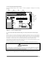
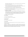
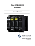
Telemotive Pre-Engineered SLTX Transmitter Remote Crane Controls Instruction Manual TCPRESLTX-0 Rev. B March 2010 Part Number: 178-00899 ©Copyright 2010 Magnetek Material Handling Table of Contents Your New Radio Remote and Service Information p.2 Safety Information P.3-8 2.1. Power “ON-OFF” Switch p.9 2.2. E-STOP p.9 2.3. Motion Push Buttons, Levers p.9 2.4. Transmitter LED Indicator p.9 2.5. Time-Out Timer p.9 3.1. SLTX Transmitter Board Set-up Information p.10 3.2. Setting Access Code (For units with no external code plug only) p.10-11 3.3. Programming Switches p.11-12 3.4. To Check Data p.12 3.5. Battery Monitor p.12 3.6. Transmit LED p.12 3.7. Batteries and Charger p.12 3.8. Changing the Channel on the Part 15 Synthesized Transmitter p.13 3.9. Channels and Frequency Designating by Count p.13-14 3.10. Standard Models p.14 3.11. Replacement Parts p.14 Telemotive PreEngineered SLTX Transmitter Instruction Manual—March 2010 1 Your New Radio Remote Thank you for your purchase of the Magnetek’s Telemotive® brand SLTX Radio Remote Crane Control. Magnetek has set a whole new standard in radio-remote performance, dependability, and value with this unique new line of belly box transmitters. Without a doubt, our Telemotive SLTX is the ultimate solution for having precise, undeterred, and safe control of your material. If your product ever needs modification or service, please contact one of our representatives at the following locations: U.S. Service Information For questions regarding service or technical information, contact: 1-866-MAG-SERV (1-866-624-7378). Magnetek Material Handling N49 W13650 Campbell Drive Menomonee Falls, WI 53051 Telephone: 800-288-8178 Website: e-mail: www.magnetekmh.com [email protected] Fax Numbers Main: 800-298-3503 Sales: 262-783-3510 Service: 262-783-3508 Canada Service Information: 4090B Sladeview Crescent Mississauga, Ontario L5L 5Y5 Canada Phone: 1-800-792-7253 Fax: 1-905-828-5707 ©2010 MAGNETEK MATERIAL HANDLING All rights reserved. This notice applies to all copyrighted materials included with this product, including, but not limited to, this manual and software embodied within the product. This manual is intended for the sole use of the person(s) to whom it was provided, and any unauthorized distribution of the manual or dispersal of its contents is strictly forbidden. This manual may not be reproduced in whole or in part by any means whatsoever without the expressed written permission of MAGNETEK. Telemotive PreEngineered SLTX Transmitter Instruction Manual—March 2010 2 PRODUCT MANUAL SAFETY INFORMATION Magnetek, Inc. (Magnetek) offers a broad range of radio remote control products, control products and adjustable frequency drives, and industrial braking systems for overhead material handling applications. This manual has been prepared by Magnetek to provide information and recommendations for the installation, use, operation and service of Magnetek’s material handling products and systems (Magnetek Products). Anyone who uses, operates, maintains, services, installs or owns Magnetek Products should know, understand and follow our instructions and safety recommendations in this manual for Magnetek Products. The recommendations in this manual do not take precedence over any of the following requirements relating to cranes, hoists and lifting devices: Instructions, manuals, and safety warnings of the manufacturers of the equipment where the radio system is used, Plant safety rules and procedures of the employers and the owners of facilities where the Magnetek Products are being used, Regulations issued by the Occupational Health and Safety Administration (OSHA), Applicable local, state or federal codes, ordinances, standards and requirements, or Safety standards and practices for the overhead material handling industry. This manual does not include or address the specific instructions and safety warnings of these manufacturers or any of the other requirements listed above. It is the responsibility of the owners, users and operators of the Magnetek Products to know, understand and follow all of these requirements. It is the responsibility of the owner of the Magnetek Products to make its employees aware of all of the above listed requirements and to make certain that all operators are properly trained. No one should use Magnetek Products prior to becoming familiar with and being trained in these requirements. WARRANTY INFORMATION FOR INFORMATION ON MAGNETEK’S PRODUCT WARRANTIES BY PRODUCT TYPE, PLEASE VISIT WWW.MAGNETEKMH.COM. Telemotive PreEngineered SLTX Transmitter Instruction Manual—March 2010 3 1.1: WARNINGS and CAUTIONS Throughout this document WARNING and CAUTION statements have been deliberately placed to highlight items critical to the protection of personnel and equipment. WARNING – A warning highlights an essential operating or maintenance procedure, practice, etc. which if not strictly observed, could result in injury or death of personnel, or long term physical hazards. Warnings are highlighted as shown below: WARNING CAUTION – A caution highlights an essential operating or maintenance procedure, practice, etc. which if not strictly observed, could result in damage to, or destruction of equipment, or loss of functional effectiveness. Cautions are highlighted as shown below: CAUTION WARNINGS and CAUTIONS SHOULD NEVER BE DISREGARDED. The safety rules in this section are not intended to replace any rules or regulations of any applicable local, state, or federal governing organizations. Always follow your local lockout and tagout procedure when maintaining any radio equipment. The following information is intended to be used in conjunction with other rules or regulations already in existence. It is important to read all of the safety information contained in this section before installing or operating the Radio Control System. Telemotive PreEngineered SLTX Transmitter Instruction Manual—March 2010 4 1.2: CRITICAL INSTALLATION CONSIDERATIONS WARNING PRIOR TO INSTALLATION AND OPERATION OF THIS EQUIPMENT, READ AND DEVELOP AN UNDERSTANDING OF THE CONTENTS OF THIS MANUAL AND THE OPERATION MANUAL OF THE EQUIPMENT OR DEVICE TO WHICH THIS EQUIPMENT WILL BE INTERFACED. FAILURE TO FOLLOW THIS WARNING COULD RESULT IN SERIOUS INJURY OR DEATH AND DAMAGE TO EQUIPMENT. ALL EQUIPMENT MUST HAVE A MAINLINE CONTACTOR INSTALLED AND ALL TRACKED CRANES, HOISTS, LIFTING DEVICES AND SIMILAR EQUIPMENT MUST HAVE A BRAKE INSTALLED. FAILURE TO FOLLOW THIS WARNING COULD RESULT IN SERIOUS INJURY OR DEATH AND DAMAGE TO EQUIPMENT. AN AUDIBLE AND/OR VISUAL WARNING MEANS MUST BE PROVIDED ON ALL REMOTE CONTROLLED EQUIPMENT AS REQUIRED BY CODE, REGULATION, OR INDUSTRY STANDARD. THESE AUDIBLE AND/OR VISUAL WARNING DEVICES MUST MEET ALL GOVERNMENTAL REQUIREMENTS. FAILURE TO FOLLOW THIS WARNING COULD RESULT IN SERIOUS INJURY OR DEATH AND DAMAGE TO EQUIPMENT. FOLLOW YOUR LOCAL LOCKOUT TAGOUT PROCEDURE BEFORE MAINTAINING ANY REMOTE CONTROLLED EQUIPMENT. ALWAYS REMOVE ALL ELECTRICAL POWER FROM THE CRANE, HOIST, LIFTING DEVICE OR SIMILAR EQUIPMENT BEFORE ATTEMPTING ANY INSTALLATION PROCEUDRES. DE-ENERGIZE AND TAGOUT ALL SOURCES OF ELECTRICAL POWER BEFORE TOUCH-TESTING ANY EQUIPMENT. FAILURE TO FOLLOW THIS WARNING COULD RESULT IN SERIOUS INJURY OR DEATH AND DAMAGE TO EQUIPMENT. THE DIRECT OUTPUTS OF THIS PRODUCT ARE NOT DESIGNED TO INTERFACE DIRECTLY TO TWO STATE SAFETY CRITICAL MAINTAINED FUNCTIONS, I.E., MAGNETS, VACUUM LIFTS, PUMPS, EMERGENCY EQUIPMENT, ETC. A MECHANICALLY LOCKING INTERMEDIATE RELAY SYSTEM WITH SEPARATE POWER CONSIDERATIONS MUST BE PROVIDED. FAILURE TO FOLLOW THIS WARNING COULD RESULT IN SERIOUS INJURY OR DEATH OR DAMAGE TO EQUIPMENT. 1.3: GENERAL Radio controlled material handling equipment operates in several directions. Cranes, hoists, lifting devices and other material handling equipment can be large, and operate at high speeds. Quite frequently, the equipment is operated in areas where people are working in close proximity to the material handling equipment. The operator must exercise extreme caution at all times. Workers must constantly be alert to avoid accidents. The following recommendations have been included to indicate how careful and thoughtful actions may prevent injuries, damage to equipment, or even save a life. 1.4: PERSONS AUTHORIZED TO OPERATE RADIO CONTROLLED CRANES Only properly trained persons designated by management should be permitted to operate radio controlled equipment. Radio controlled cranes, hoists, lifting devices and other material handling equipment should not be operated by any person who cannot read or understand signs, notices and operating instructions that pertain to the equipment. Radio controlled equipment should not be operated by any person with insufficient eyesight or hearing or by any person who may be suffering from a disorder or illness, is taking any medication that may cause loss of equipment control, or is under the influence of alcohol or drugs. Telemotive PreEngineered SLTX Transmitter Instruction Manual—March 2010 5 1.5: SAFETY INFORMATION AND RECOMMENDED TRAINING FOR RADIO CONTROLLED EQUIPMENT OPERATORS Anyone being trained to operate radio controlled equipment should possess as a minimum the following knowledge and skills before using the radio controlled equipment. The operator should: have knowledge of hazards pertaining to equipment operation have knowledge of safety rules for radio controlled equipment have the ability to judge distance of moving objects know how to properly test prior to operation be trained in the safe operation of the radio transmitter as it pertains to the crane, hoist, lifting device or other material handling equipment being operated have knowledge of the use of equipment warning lights and alarms have knowledge of the proper storage space for a radio control transmitter when not in use be trained in transferring a radio control transmitter to another person be trained how and when to report unsafe or unusual operating conditions test the transmitter emergency stop and all warning devices prior to operation; testing should be done on each shift, without a load be thoroughly trained and knowledgeable in proper and safe operation of the crane, hoist, lifting device, or other material handling equipment that utilizes the radio control know how to keep the operator and other people clear of lifted loads and to avoid “pinch” points continuously watch and monitor status of lifted loads know and follow cable and hook inspection procedures know and follow the local lockout and tagout procedures when servicing radio controlled equipment know and follow all applicable operating and maintenance manuals, safety procedures, regulatory requirements, and industry standards and codes The operator shall not: lift or move more than the rated load operate the material handling equipment if the direction of travel or function engaged does not agree with what is indicated on the controller use the crane, hoist or lifting device to lift, support or transport people lift or carry any loads over people operate the crane, hoist or lifting device unless all persons, including the operator, are and remain clear of the supported load and any potential pinch points operate a crane, hoist or lifting device when the device is not centered over the load Telemotive PreEngineered SLTX Transmitter Instruction Manual—March 2010 6 operate a crane, hoist or lifting device if the chain or wire rope is not seated properly in the sprockets, drum or sheave operate any damaged or malfunctioning crane, hoist, lifting device or other material handling equipment change any settings or controls without authorization and proper training remove or obscure any warning or safety labels or tags leave any load unattended while lifted leave power on the radio controlled equipment when the equipment is not in operation operate any material handling equipment using a damaged controller because the unit may be unsafe operate manual motions with other than manual power operate radio controlled equipment when low battery indicator is on WARNING THE OPERATOR SHOULD NOT ATTEMPT TO REPAIR ANY RADIO CONTROLLER. IF ANY PRODUCT PERFORMANCE OR SAFETY CONCERNS ARE OBSERVED, THE EQUIPMENT SHOULD IMMEDIATELY BE TAKEN OUT OF SERVICE AND BE REPORTED TO THE SUPERVISOR. DAMAGED AND INOPERABLE RADIO CONTROLLER EQUIPMENT SHOULD BE RETURNED TO MAGNETEK FOR EVALUATION AND REPAIR. FAILURE TO FOLLOW THIS WARNING COULD RESULT IN SERIOUS INJURY OR DEATH AND DAMAGE TO EQUIPMENT. 1.6: TRANSMITTER UNIT Transmitter switches should never be mechanically blocked ON or OFF. When not in use, the operator should turn the transmitter OFF. A secure storage space should be provided for the transmitter unit, and the transmitter unit should always be placed there when not in use. This precaution will help prevent unauthorized people from operating the material handling equipment. Spare transmitters should be stored in a secure storage space and only removed from the storage space after the current transmitter in use has been turned OFF, taken out of the service area and secured. 1.7: PRE-OPERATION TEST At the start of each work shift, or when a new operator takes control of the crane, operators should do, as a minimum, the following steps before making lifts with any crane or hoist: Test all warning devices. Test all direction and speed controls. Test the transmitter emergency stop. Telemotive PreEngineered SLTX Transmitter Instruction Manual—March 2010 7 1.8: BATTERIES WARNING KNOW AND FOLLOW PROPER BATTERY HANDLING, CHARGING AND DISPOSAL PROCEDURES. IMPROPER BATTERY PROCEDURES CAN CAUSE BATTERIES TO EXPLODE OR DO OTHER SERIOUS DAMAGE. FAILURE TO FOLLOW THIS WARNING COULD RESULT IN SERIOUS INJURY OR DEATH AND DAMAGE TO EQUIPMENT. 1.9: BATTERY HANDLING Use only batteries approved by Magnetek for the specific product. Do not dispose of a battery pack in fire; it may explode. Do not attempt to open the battery pack. Do not short circuit the battery. For intrinsically safe environments only use specified Magnetek Telemotive intrinsically safe batteries. Keep the battery pack environment cool during charging operation and storage (i.e., not in direct sunlight or close to a heating source). 1.10: BATTERY CHARGING For those transmitters equipped with battery chargers, please familiarize all users with the instructions of the charger before attempting to use. Do not attempt to charge non-rechargeable battery packs. Avoid charging partially discharged rechargeable batteries to help prolong battery cycle life. Avoid charging the battery pack for more than 24 hours at a time. Do not charge batteries in a hazardous environment. Do not short the charger. Do not attempt to charge a damaged battery. Use only Magnetek Telemotive approved chargers for the appropriate battery pack. Do not attempt to use a battery that is leaking, swollen or corroded. Charger units are not intended for outdoor use. Use only indoors. 1.11: BATTERY DISPOSAL Before disposing of batteries consult local and governmental regulatory requirements for proper disposal procedure. . Telemotive PreEngineered SLTX Transmitter Instruction Manual—March 2010 8 CAUTION Before operating the transmitter, familiarize yourself with all safety information in this manual and any other local, state, or federal rules or regulations already in existence. 2.1: Power “ON-OFF” Switch (Turns transmitter and receiver ON and OFF). Pressing the ON/OFF push-button switch (Part 15) starts the transmitter. If the transmitter is ON the BATT MONITOR light is ON or flashing. Pushing the ON/OFF button again (Part 15 will turn the transmitter and receiver OFF. 2.2: E-STOP (For emergency stopping only). When depressed, the MCR relay is opened, the receiver shuts down, and power to the equipment is immediately stopped. Under normal operating conditions, the E-STOP must be in the raised position. The transmitter must be turned OFF and ON again to restore normal operation. To be used for emergency stopping only, not for normal system shut down. 2.3: Motion Push Buttons, Levers. To activate motor functions, press and hold the lever that corresponds to the desired motion. The extent to which the push-button or lever is pushed, dictates the speed of the motor function. 2.4: Transmitter LED Indicator. The transmitter LED (red) indicates the transmitter is on, or transmitting, or has a low battery voltage. A slow flash rate indicates the unit is ON. A rapid flash rate indicates the unit is transmitting (when a function or control is activated). If the battery goes below a safe level, the LED will not light. Replace battery immediately. 2.5: Time-Out-Timer. Unless this function is disabled, the transmitter will turn itself OFF if not used for 15 minutes. Telemotive PreEngineered SLTX Transmitter Instruction Manual—March 2010 9 3.1: SLTX Transmitter Board Setup Information. The SLTX Transmitter Board is shown in Figure 3-1. Refer to paragraphs 3.1 through 336 for servicing procedures. M5 J29 J32 J28 J31 M4 J27 J30 J34 J33 J17 J35 M3 J21 M6 J36 J38 J3 J2 J7 J6 J19 J18 J14 J13 J12 J11 J10 16 15 14 13 12 11 10 9 ANT. J4 M2 8 7 6 5 4 3 2 J5 J9 J20 Power connector J8 Battery 1 J37 OFF M7 TP2 GND TP5 POWER CONTROL TP4 +5V TP3 DATA OFF OFF OFF 8---------1 8---------1 8---------1 8---------1 SW2 “A” SW1 SW1 “B” “A” SW4 “D” SW3 “C” J23 EXTERNAL CODE PLUG EPROM E10642 J1 J24 ON/OFF LED Key switch J15 ON/OFF switch J25 EMS (ESTOP) J26 Not used RPOT1 J9 Firmware Loading Connector TP6 J40 Firmware Number Label Reset RPOT2 J39 TP1 Figure 3-1. SLTX Transmitter Board 3.2: Access Codes Switches. (SW1 and SW2). Setting Access Code (for units with no external code plug only). The access code is set at the factory and should not be changed unless absolutely necessary. If a spare transmitter unit is used, the receiver unit access code should be changed to match the access code of the spare transmitter unit. For Part 15 systems the access codes are printed on a white label on the outside of any transmitter and may be matched to “A” and “B” on the receiver CPU Board without having to open the transmitter housing. Switch SW2 (B) in the transmitter must match switch (B) on the receiver CPU Board and switch SW1 (A) in the transmitter must match switch (A) on the receiver CPU Board. If you are reprogramming a spare transmitter make sure the other transmitter is securely taken out of service. WARNING TWO OPERATIONAL TRANSMITTERS WITH THE SAME ACCESS CODES OPERATING AT THE SAME TIME IS A DEFINITE SAFETY HAZARD. FAILURE TO FOLLOW THIS WARNING COULD RESULT IN SERIOUS INJURY OR DEATH AND DAMAGE TO EQUIPMENT. Telemotive receivers are shipped with the access code settings for the transmitter marked on the receiver door. Telemotive PreEngineered SLTX Transmitter Instruction Manual—March 2010 10 Also a label on the transmitter lists the access code settings inside. The positions on the transmitter label match the switch settings. The “1” by A1 means the switch position A1 should be “ON” and “0” means A1 should be “OFF”. a. Changing Transmitter Access Codes. WARNING AFTER CHANGING THE ACCESS CODES ON THE TRANSMITTER, TEST THE UNIT BY TURNING IT ON AND OFF NEAR THE APPROPRIATE RECEIVER. IF THE RECEIVER DOES NOT RESPOND, DO NOT ACTIVATE A FUNCTION BUTTON! THE TRANSMITTER MAY HAVE THE WRONG ACCESS CODE, WHICH COULD MOVE ANOTHER CRANE. RE-CHECK THE ACCESS CODE IN THE TRANSMITTER AND RETEST. FAILURE TO FOLLOW THIS WARNING COULD RESULT IN SERIOUS INJURY OR DEATH AND DAMAGE TO EQUIPMENT. 3.3: SLTX Programming Switches. The programming switch SW3 controls the following features: (These only apply to units originally programmed to utilize these features). a. 10K Series SLTX Programming Switches SW3 and SW4 Programming. i. Transmitter programming SW3. ii. Positions 1-4, 6 and 7 (Keep turned “OFF”). iii. Position 5 Activate E-STOP enable (Normally keep turned “OFF”). Turn SW3-5 “ON” to enable Active E-STOP. iv. Position 8 Time-out-timer Disable. (Normally keep turned “OFF”). The transmitter has an approximate 15-minute time-out-timer. If the transmitter is not used for over 15 minutes it will shut down. This transmitter time-out-timer function is transmitter dip switch selectable. SW3 position 8 disables the time-out-timer. Turning SW3-8 “ON” disables the time-out-timer. b. Transmitter programming SW4. i. Position SW4 1 and 2 Mode Enable. (Standard Mode 1, keep 1-2 turned “OFF”). Mode 1, SW4 1-2 all “OFF”. The 10K12 single speed system comes standard configured this way from the factory with three motion controls and six auxiliaries (controlled by the toggle switches). The 10K12 2speed system comes standard configured this way from the factory with three 2-speed controls and three auxiliaries (controlled by the toggle switches, the rotary is non-functional). Mode 2, SW4 1 turned “OFF” and SW4 2 turned “ON”. The 10K12 2-speed system configured this way is able to control four 2-speed motion controls and no auxiliaries. This gives bridge, trolley, main and aux hoist. The rotary selector switch functions are H1 main hoist, H2 aux hoist and B both main and aux hoist (the toggle switches are non-functional). Mode 3, SW4 1 and 2 turned “ON”. The SLTX transmitter will control up to 5 motors using the rotary selector switch. This mode reconfigures two of the 10K12 auxiliary outputs (Aux 1 and Aux 2) to be external motor select functions by the rotary switch. In this mode the auxiliary toggle switches Aux 1 and Aux 2 are disabled. When the rotary switch is in the H1 or H2 position Aux 1 relay or Aux 2 relay will Telemotive PreEngineered SLTX Transmitter Instruction Manual—March 2010 11 pull in respectively whenever trolley or hoist lever is moved. When the rotary switch is in B position both Aux 1 and Aux 2 relays will pull in. i. Position SW4-3 Disable Tandem for Hoist and Trolley. (Normally keep turned “OFF”). For cranes with auxiliary hoists and/or trolleys, turning this switch “ON” disables the transmitter selector switch “B” position (both function) that selects tandem operation of hoist or trolley. ii. Position SW4-4 Invert Crane Select Aux. Outputs. (Normally keep turned “OFF”). For cranes that use the select function only, turning this switch “ON” inverts the select function operation so that the relay closes for the unselected function. iii. Positions SW-5-7 Extended Crane Control Configurations. (Standard all “OFF”, otherwise see the appropriate receiver manual). The 10K12 SLTX transmitter is available with extended crane control configurations. These options are switch configurable on the transmitter. The eight-position dip switches SW3 and SW4 on the transmitter can provide all configurations with a single transmitter CPU EPROM for the 2-speed transmitter. See your receiver manual for available configurations and the switch programming needed to provide them. iv. Position 8 No Function (keep turned off). 3.4: To Check Data. 1). For data input use Data pin on RF Module. 2). Use RF SW pin on RF Module for External Trigger input. 3). Use TP2 for Ground. 3.5: Battery Monitor. Set to 5.8 Volts by R6 and R8 not adjustable. 3.6: Transmit LED. This flashing red LED flashes rapidly during transmit, slowly when unit is ON and turns out when battery is low. 3.7: Batteries and Charger. Two batteries are available for the Pre-engineered SLTX, a disposable alkaline battery BT120-0 and a rechargeable 7.2V NiMH (BT122-0). The battery charger for the BT122-0 is the E10759-0. Two piggyback chargers (E10759-1) can be used with one E10759-0. This will allow three batteries to be charged at the same time from one power supply. This is the most that can be done at one time. Please see your charger manual for additional details. Please follow local regulations for the disposal of any battery product. Telemotive PreEngineered SLTX Transmitter Instruction Manual—March 2010 12 3.8: Changing the Channel on the Part 15 Synthesized Transmitter. The channel can be changed by removing the logic board from the bottom housing. Locate the rotary switches on the RF Transmitter Board (see Figure 3.2 SLTX Synthesizer Board). The rotary switch nearest the corner of the board is the “ones” place-value selection (0-9). The rotary switch near the middle of the board is the “tens” placevalue selection (10, 20, and 30). Figure 3.2 SLTX Synthesizer Board AK 20 would be Tens Ones 2 0 Compliance Statement (Part 15.19) This device complies with Part 15 of the FCC Rules. Operation is subject to the following two conditions: 1. This device may not cause harmful interference, and 2. This device must accept any interference received, including interference that may cause undesired operation. Warning (Part 15.21) Changes or modifications not expressly approved by the party responsible for compliance could void the user’s authority to operate the equipment. This portable transmitter with its antenna complies with FCC’s RF exposure limits for general population / uncontrolled exposure. 3.9: Channel and Frequency Designations by Count Indicator Channel Actual Count Designator Frequency 01. AK01 439.8 MHz 02. AK02 439.6 MHz 03. AK03 439.4 MHz 04. AK04 439.2 MHz 05. AK05 439.0 MHz 06. AK06 438.8 MHz 07. AK07 438.6 MHz 08. AK08 438.4 MHz 09. AK09 438.2 MHz 10. AK10 438.0 MHz 11. AK11 437.8 MHz 12. AK12 437.6 MHz 13. AK13 437.4 MHz 14. AK14 437.2 MHz 15. AK15 437.0 MHz 16. AK16 436.8 MHz Telemotive PreEngineered SLTX Transmitter Instruction Manual—March 2010 13 Channel and Frequency Designations by Count (continued) Indicator Channel Actual Count Designator Frequency 17. AK17 436.6 MHz 18. AK18 436.4 MHz 19. AK19 436.2 MHz 20. AK20 436.0 MHz 21. AKA00 433.125 MHz 22. AKA01 433.325 MHz 23. AKA02 433.525 MHz 24. AKA03 433.725 MHz 25. AKA04 433.925 MHz 26. AKA05 434.125 MHz 27. AKA06 434.325 MHz 28. AKA07 434.525 MHz 29. AKA08 434.725 MHz 30. AK38 432.4 MHz 31. AK50 430.0 MHz 3.10: Standard Models “SLTX-3L-3M-3S” has 3 levers and 3 speeds “SLTX-3L-3M-2S” has 3 levers and 2 speeds “SLTX-3L-5M-3S” has 3 levers and 3 speeds “SLTX-3L-3M-5S” has 3 levers and 5 speeds 3.11: Replacement Parts. If your transmitter ever needs repair, we always recommend that you contact Magnetek for service. If you need to refer to a parts list please refer to your transmitter’s drawing that was included in the shipment of your transmitter. If you have trouble locating the drawing, the latest version is available on our web site at www.magnetekmh.com. For replacement batteries and chargers, your options are as follow: Battery and Charger 9V Alkaline (disposable) 7.2V NiMH (re-chargeable) Charger for BT122-0 Piggyback Charger (2 per E10759-0) BT120-0 BT122-0 E10759-0 E10759-1 Telemotive PreEngineered SLTX Transmitter Instruction Manual—March 2010 14