1
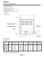
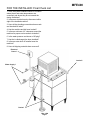
MFE400
INTRODUCTION
To the owner or user: The service manual you are
reading is intended to provide you, and the
maintenance or service technician with the
information needed to install, start up, clean,
maintain, and service this ice system.
TABLE OF CONTENTS
For the Installer
Specifications . . . . . . . . . . . . . . . . . . . . . . . . . . . . . . . . . . .
Page 2
Location/Assembly . . . . . . . . . . . . . . . . . . . . . . . . . . . . . . . .
Page 4
For the Plumber . . . . . . . . . . . . . . . . . . . . . . . . . . . . . . . . . . . . .
Page 5
For the Electrician
. . . . . . . . . . . . . . . . . . . . . . . . . . . . . . . . . . .
Page 6
Final Check List . . . . . . . . . . . . . . . . . . . . . . . . . . . . . . . . . . . . .
Page 7
Start Up
. . . . . . . . . . . . . . . . . . . . . . . . . . . . . . . . . . . . . . . . .
Page 8
Component Description . . . . . . . . . . . . . . . . . . . . . . . . . . . . . . . . .
Page 9
Electrical Sequence . . . . . . . . . . . . . . . . . . . . . . . . . . . . . . . . . . .
Page 10
Operation . . . . . . . . . . . . . . . . . . . . . . . . . . . . . . . . . . . . . . . . .
Page 11
Maintenance & Cleaning . . . . . . . . . . . . . . . . . . . . . . . . . . . . . . . . .
Page 13
Service Diagnosis
Page 15
. . . . . . . . . . . . . . . . . . . . . . . . . . . . . . . . . . .
Removal and Replacement
Ice Breaker and Auger . . . . . . . . . . . . . . . . . . . . . . . . . . . . . .
Page 17
Water Seal
. . . . . . . . . . . . . . . . . . . . . . . . . . . . . . . . . . .
Page 17
Gearmotor Assembly . . . . . . . . . . . . . . . . . . . . . . . . . . . . . . .
Page 18
Reservoir . . . . . . . . . . . . . . . . . . . . . . . . . . . . . . . . . . . . .
Page 20
Refrigeration . . . . . . . . . . . . . . . . . . . . . . . . . . . . . . . . . . . . . . .
Page 21
Parts lists and wiring diagrams are located
in the center of this manual, printed on
yellow paper.
May 1994
Page 1
MFE400
FOR THE INSTALLER
The MFE400 is designed to fit the following
Scotsman storage bins.
BH550 with bin top KBT20
HTB555 with bin top KBT20
When installing the new system, check that
everything needed is on site:
Correct Ice Machine (voltage and type)
Correct Bin
Correct Bin Top
Legs for the bin
21"
1 -7/16"
Condenser Inlet, 3/8" O.D.
Tube (Water Cooled)
Water Inlet
3/8" Male Flare
Condenser Drain 3/8"
O.D. Tube (Water Cooled)
Electrical
Inlet
3.5"
2"
2.5"
8"
Drain 7/16" I.D.
Hose
9.5"
SPECIFICATIONS:
ICE MAKER
Model
Number
Model
Series
Dimensions
(w/o Bin)
H" x W" x D"
Basic
Electrical
Condenser
Type
Minimum
Circuit
Ampacity+
MFE400AS-1
MFE400WS-1
MFE400WS-1
MFE400AS-6
MFE400WS-6
MFE400WS-6
A or B
A
B
A or B
A
B
21.5 x 21 x 22
same
same
same
same
same
115/60/1
same
same
230/50/1
same
same
Air
Water
Water
Air
Water
Water
11.1
10.2
10.2
5.6
5.1
5.1
*Minimum Circuit Ampacity is used to determine
wire size and type per National Electric Code.
September 2005
Page 2
Maximum Refrigerant
Fuse Size
Charge
(R-134a)
15
15
15
15
15
15
15 oz.
15 oz.
14 oz.
15 oz.
15 oz.
14 oz.
MFE400
FOR THE INSTALLER
Installation Limitations:
Water Limitations:
This ice system is designed to be installed indoors,
in a controlled environment:
An ice machine is a food manufacturing plant; it
takes in a raw material, water, and turns it into a
food product, ice. The purity of the water is very
important in obtaining pure ice and in maximizing
product life. This section is not intended as a
complete resource for water questions, but it does
offer these general recommendations:
Min
Max
Air Temperature
0
50 F.
1000F.
Water Temperature
400F.
1000F.
Water Pressure
20 psi
80 psi
Voltage
-10%
+10%
(Compared to the Nameplate)
Operating the machine outside of the limitations is
misuse and can void the warranty.
Scotsman Ice Systems are designed and
manufactured with the highest regard for safety
and performance. They meed or exceed the
standards of UL, NSF, and CSA.
Scotsman assumes no liability or responsibility of
any kind for products
manufactured by
Scotsman that have
been altered in any
way, including the use
of any part and/or other
components not
specifically approved by
Scotsman.
Scotsman reserves the
right to make design
changes and/or
improvements at any time.
Specifications and design
changes are subject to
change without notice.
1. Filter the water used to make ice. That is the
water going to the “potable” water connection.
Water filters vary greatly in ability and function.
Install one that filters out suspended solids to a
dimension of 5 microns or smaller. The finer the
filter the better, but finer filters will clog sooner that
course ones. It may be necessary to add a course
filter ahead of the fine filter to prolong filter life.
2. Check with a water treatment specialist for a
water test, and recommendations regarding filters
and treatment.
Service Limitations:
There must be space
above, to at least one
side, to the back, and of
course the front for
service access.
Airflow
May 1994
Page 3
MFE400
FOR THE INSTALLER
Location
After uncrating and inspection, the unit is ready to
be installed.
It is important that the machine be installed in a
location where it has enough space around it for
service, and a minimum of 6" be allowed all sides
for air circulation. The machine, when air cooled,
draws air in the front, and exhausts it out the sides
and back.
Try to avoid hot, dirty and crowded locations. Be
sure that the location for the machine is within the
limitations described on page 3.
Storage Bin
Tip the uncrated storage bin on its back, using
parts of the carton to protect the exterior finish.
Install the legs into the threaded holes in the
bottom of the bin. Turn the leg levelers all the way
in preparation for leveling later.
5. Remove the rubber cap from the top of the ice
chute. Leave one hose clamp on the chute.
6. Push the ice chute against the stainless spout
(the end of the spout will go into the chute).
7. Slide the rubber cap over the top of the stainless
spout. Push down until it fits tightly around the
spout.
8. Secure the rubber cap to the spout with the two
hose clamps, in the molded grooves; one above
and one below. Keep hose clamp screws away
from evaporator.
9. Attach the insulation halves around the top of
the evaporator. Secure with the ty-wrap provided.
Finish installation per service manual.
HOSE CLAMP
RUBBER CAP
Return the bin to the upright position, remove
paper covering the bin gasket.
MOLDED
GROVES
Install bin top if required.
Note: Do not push bin into position: but lift it there.
Pushing a bin, especially one with ice in it, can
cause damage to the legs and the leg mounts.
HOSE CLAMP
ICE CHUTE
Ice Maker
METAL ICE
SPOUT
The machine is heavy, so the use of a mechanical
lift is recommended for lifting the machine high
enough to install on top of the bin. After the
machine is placed on the bin, line it up so that the
ice discharge opening in the base of the machine
is over the open hole in the bin top.
ICE CHUTE INSTALLATION
Ice Chute Installation
After the MFE400 has been installed on the ice
storage bin, the ice chute needs to be installed:
HOSE
CLAMP
1. With the top panel off, remove all packing
material (bubble pack) from above the ice chute
and chute cap. Cut the ty-wrap holding the chute
assembly in place.
RUBBER
CAP
METAL SPOUT
2. Remove the insulation halves and ty-wrap
packed inside the cabinet, retain for later use.
3. Remove the cardboard support from under the
ice chute.
4. Insert the ice chute/bin thermostat assembly into
the large hole in the bottom of the ice machine.
Check that bin thermostat cap tube is free from
contact with most components.
May 1994
Page 4
HOSE CLAMP
ASSEMBLED VIEW
MFE400
FOR THE PLUMBER
CONFORM TO ALL APPLICABLE CODES
Water Inlet
Air Cooled: The recommended water supply is
cold water. Use 3/8" O.D. copper tubing, connect
to the 3/8" male flare at the back of the cabinet.
Install a hand valve near the machine to control
the water supply.
Water Cooled: A separate 3⁄8" O.D. copper tube
should be connected to the condenser inlet, with a
separate hand valve to control it.
Drains
Air cooled: There is one 7⁄16" I.D.
hose to connect to for a drain. This
drain is a gravity drain, and a
minimum of 1⁄4" per foot fall is needed
for horizontal portions of the drain
line.
The ideal drain receptacle is a
trapped and vented floor drain.
Use only rigid tubing.
Water Cooled Models: In addition to
the above mentioned drain, separate
condenser drain must be installed.
Connect to the 3⁄8" condenser drain
tube.
Storage Bin: A separate gravity type
drain needs to be run. This drain line
should be insulated.
CONDENSER
WATER INLET
(Water Cooled)
OVERFLOW
DRAIN
POTABLE WATER
INLET
WATER FILTER
(FIELD SUPPLIED)
CONDENSER DRAIN
(Water Cooled)
BIN DRAIN
FLOOR
DRAIN GRILL
September 2005
Page 5
MFE400
FOR THE ELECTRICIAN
CONFORM TO ALL APPLICABLE CODES
The electrical power to the unit is to be wired
through the cabinet to the control box. In the
control box, connect to the terminal strip provided.
1. Remove the front, top and right side panels.
2. Remove the control box cover.
3. Route the power cord thru the cabinet to the
control box.
4. Connect wires to the terminal strip.
ELECTRICAL POWER
SUPPLY
5. Replace all panels.
Check the nameplate (located on the back of the
cabinet) for the voltage requirements, and for the
minimum circuit ampacity. The machine requires
a solid chassis to earth ground wire.
The ice maker should be
connected to it’s own electrical
circuit so that it is individually
fused. Voltage variation must
remain within design limitations,
even under starting conditions.
All external wiring must conform to
national, state, and local electrical
codes. The use of e licensed
electrician is required to perform
the electrical installation.
CONNECT ELECTRICAL
POWER TO ICE MAKER
THROUGH ELECTRICAL
INLET HOLE AND INTO
CONTROL BOX
May 1994
Page 6
MFE400
FOR THE INSTALLER: Final Check List
1. Is the ice system installed indoors in a location
where the air and water temperatures are
controlled, and where they do not exceed the
design limitations?
2. Is there an electrical service disconnect within
sight of the installed machine?
3. Have all the plumbing connections been made
and checked for leaks?
4. Has the machine and bin been leveled?
5. Is there a minimum of 6" clearance around the
machine for proper service and air circulation?
6. Is the water pressure a minimum of 20 psig?
7. Has the ice discharge tube been installed?
8. Is there a water shut off installed near the
machine?
9. Have all shipping materials been removed?
Electrical
Power?
Leveled?
Water Supply?
Drains?
May 1994
Page 7
MFE400
INITIAL START UP
1. Remove screws and the front panel.
2. Open the water shut off valve.
3. Observe that the water flows into the water
reservoir, fills up the water inlet tube to the
evaporator, the float moves up with the water level,
and the float shuts off the water flow, about 3⁄8"
below the molded horizontal line on the water
reservoir.
4. Switch on the electrical power to the unit.
5. Switch the master switch to ON.
6. After a few minutes of operation: water should
begin to flow from the reservoir to the evaporator;
the air cooled condenser should begin to
discharge warm air, or the water cooled condenser
should beginning to discharge warm water; and
the unit should begin to drop ice into the storage
bin.
Note: For High Altitude Installations an Altitude
Adjustment May Be Required:
(11-0354-01, 20 Ranco brand bin thermostats only)
7. Let the unit operate for 15-30 minutes, checking
for water leaks, or excessive noise from vibrating
components.
Adjustment
8. Block off the ice discharge tube, and check if the
bin thermostat shuts off the machine. After it shuts
off the compressor, the auger motor should run for
a few minutes more. Allow the ice in the tube to fall
away, and check that the compressor restarts.
Range
Screw CW
9. Explain the operation and maintenance
requirements to the user, inform the user of the
telephone number of the service agency servicing
the machine, and give the user the service manual.
May 1994
Page 8
Altitude (ft.
Amount of
above seal level) adjustment from
factory setting
2,000
35o
4,000
90o
6,000
145o
8,000
190o
MFE400
COMPONENT LOCATION: Control Box
Auger Delay Pressure Control: This pressure
switch, connected to the low side of the
refrigeration system, controls the auger drive
motor.
High Pressure Control: The pressure switch,
used on water cooled models only, is designed to
open and shut off the machine should the high
side refrigeration pressure become too high,
usually as a result of not enough water through the
water cooled condenser.
It is a manual reset.
On-Off switch: This toggle
High Pressure
switch shuts off the machine. It is
Control
not a complete disconnect.
Bin Thermostat: This thermostat
turns the machine on and off in
response to changes in
temperature of the capillary tube.
It opens at 350 F. and closes at
450 F. The capillary tube is
mounted on the inside of the ice
chute.
Auger Delay Control
Bin Thermostat
On-Off Switch
May 1994
Page 9
MFE400
ELECTRICAL SEQUENCE
There are two circuits in the MFE400: one is a
series circuit with several switches connected in
series to the compressor. The other is a parallel
branch of the series circuit, controlling the gear
drive motor.
• The series circuit begins at the terminal strip in
the control box. From there, the line side power
is connected to the Master Switch.
• When the master switch is closed, the power is
then connected to the Spout Switch. This
switch, located on the top of the ice chute, is
closed unless the ice chute has overfilled with
ice, it is an automatic reset.
• From the spout switch the line side power now
is connected to the High Pressure Control
(water cooled). This control, connected to the
refrigeration system, is designed to open
whenever higher pressures are sensed. The
high pressure control is a manual reset.
• The line side power is also connected, in a
parallel circuit, to terminal 1 of the Auger Delay
pressure control. This pressure control,
connected to the low side of the refrigeration
system, is designed as a by-pass circuit to the
auger drive motor whenever the low side
refrigerant pressure is at it’s normal ice making
range. At start up, the contacts between
terminals 1 and 2 are open. The line side power
does not pass any further through the auger
delay pressure control, until the compressor
starts, and the low side pressure drops.
• The next control the power is connected to is
the Low Water Pressure Control. This switch is
designed to open should the water pressure to
the machine drop too low.
• The next control is the Bin Thermostat. It is
closed when there is no ice on the portion of the
control inside the ice chute. It is open when
there is ice on the portion of the control inside
the ice chute. Closing of the bin thermostat
begins the process of making ice, because the
line side power now goes to the compressor,
gearmotor, and if air cooled, the fan motor.
• Power is initially connected to the gearmotor
through contacts 3 and 2 of the auger delay
pressure control. This causes the auger motor
to start and run. At the same time, if the
centrifugal switch on top of the gearmotor
closes (meaning the motor is at full speed) the
compressor is connected to the neutral side of
the power supply, and the compressor begins
to run.
• As the compressor runs, the low side or suction
pressure begins to fall, when it reaches a preset
point, the contacts within it move, opening 3
and 2, then closing 1 and 2. The power for the
gearmotor is then connected to a point in the
series circuit ahead of the low pressure control,
the low water pressure control and the bin
thermostat, so that if any of these open, the
gearmotor will continue to run, pushing ice out
of the evaporator.
May 1994
Page 10
MFE400
OPERATION: Water
Water enters the machine through the 1/4" male
flare at the rear of the cabinet, goes past the water
pressure switch and then to the water reservoir
which it enters through the float valve. The water
then goes out the bottom of the reservoir tank to
the bottom of the evaporator.
Reservoir overflows routed to the drain. Water
cooled models have a separate water circuit for
the cooling water: it enters the fitting at the rear,
goes to the water regulating valve, then to the
water cooled condenser and down the drain.
WATER RESERVOIR FLOAT VALVE
WATER SEAL
SAFETY
SWITCH
SPOUT
PRESSURE
SWITCH
ICE
CHUTE
WATER
INLET
RESERVOIR
OVERFLOW
DRAIN
AUGER DRIVE
MOTOR
ICE AND WATER SCHEMATIC
"B" MODEL
May 1994
Page 11
BIN
THERMOSTAT
BRACKET
MFE400
OPERATION: Refrigeration
Beginning at the compressor, the refrigerant is
compressed into a high temperature gas. The
discharge line directs this gas to the condenser. At
the condenser (air or water cooled) the gas is
cooled by either air or water and it then condenses
into a liquid. This high pressure liquid then goes
through the liquid line to the capillary tube. The
capillary tube meters liquid refrigerant into the
evaporator, the volume of liquid refrigerant
depending upon the temperature of the
evaporator; warmer evaporators get more
refrigerant and colder evaporators get less.
System Characteristics
Typical Low Side Pressure 13 -14 PSIG
Typical High Side Pressure
• (air cooled) 137 - 170 PSIG
• (water cooled) 135-140 PSIG
Typical auger drive motor amp draw: 2-8 - 3.1
Refrigerant Charge: 15 oz. of R-134a
At the evaporator, the refrigerant enters an area of
relatively low pressure, where it can easily “boil off”
or evaporate. As it evaporates, it absorbs heat
from the evaporator and whatever is in contact
with it (such as the water inside it). After the
evaporator, the refrigerant, now a low pressure
vapor, goes through the suction line back to
compressor, where the cycle is repeated.
EVAPORATOR
ACCUMULATOR
CAPILLARY TUBE
COMPRESSOR
DRYER
CONDENSER
May 1994
Page 12
MFE400
MAINTENANCE AND CLEANING
A Scotsman Ice System represents a sizable investment of time and money in any company’s business. In
order to receive the best return for that investment, it MUST receive periodic maintenance.
It is the USER’S RESPONSIBILITY to see that the unit is properly maintained. It is always preferable, and
less costly in the long run, to avoid possible down time by keeping it clean; adjusting it as needed; and by
replacing worn parts before they can cause failure. The following is a list of recommended maintenance
that will help keep the machine running with a minimum of problems.
Maintenance and Cleaning should be scheduled at a minimum of twice per year.
ICE MAKING SYSTEM: In place cleaning
1. Check and clean any water treatment devices, if
any are installed.
2. Remove screws and remove the top and front
panels.
3. Move the ON-OFF switch to OFF.
4. Open the door to the ice storage bin, and
remove the ice.
5. Remove the cover to the water reservoir and
block the float up.
6. Drain the water reservoir and freezer assembly.
7. Prepare the cleaning solution: Mix eight ounces
of Scotsman Ice Machine Cleaner with three
quarts of hot water. The water should be between
90-115 degrees F.
8. Slowly pour the cleaning solution into the water
reservoir until it is full. Wait 15 minutes, then
switch the master switch to ON.
Scotsman Ice Machine
Cleaner contains acids.
These compounds may
cause burns.
If swallowed, DO NOT
induce vomiting. Give
large amounts of water or
milk. Call Physician
immediately. In case of
external contact, flush
with water.
KEEP OUT OF THE
REACH OF CHILDREN.
9. As the ice maker begins to use water from the
reservoir, continue to add more cleaning solution
to maintain a full reservoir.
10. After all of the cleaning solution has been
added to the reservoir, and the reservoir is nearly
empty, switch the master switch to OFF.
11. After draining the reservoir, as in step 6, wash
and rinse the water reservoir.
12. Go thru steps 13 - 18 to sanitize the ice
machine water system.
13. Mix two gallons of sanitizer solution. Use an
approved sanitizer.
A possible sanitizing solution may be obtained by
mixing 1 ounce of household bleach with 2 gallons
of warm (90-115oF.) potable water.
14. Slowly pour the sanitizer solution into the water
reservoir until it is full, then switch the master
switch to ON.
15. As the ice maker begins to use water from the
reservoir, continue to add more cleaning solution
to maintain a full reservoir.
16. After 1⁄2 of the cleaning solution has been
added to the reservoir, and the reservoir is nearly
empty, switch the master switch to OFF.
17. After draining the reservoir, as in step 6,
thoroughly wash and rinse the interior of the water
reservoir and reservoir cover with sanitizer solution.
18. Remove the block from the float in the water
reservoir. Place the cover on the reservoir.
Switch the master switch to ON
19. Continue ice making for at least 15 minutes, to
flush out any cleaning or sanitizing solution.
DO NOT USE any ice produced from the
cleaning solution.
Be sure no ice remains in the bin.
20. Switch the master switch to OFF.
21. Remove all ice from the storage bin.
22. Add warm water to the ice storage bin and
thoroughly wash and rinse all surfaces within the
bin.
23. Sanitize the bin interior with the balance of the
sanitizer mixed in step 14 by thoroughly washing
all interior surfaces of the bin, bin door and door
frame with the sanitizer solution.
24. Switch the master switch to ON.
25. Replace the top and the front panels. The
machine is now ready for continued automatic
operation.
January 1996
Page 13
MFE400
MAINTENANCE AND CLEANING
///////////////////////////WARNING/////////////////////////////
4. Replace the water seal, see the instructions
under "Removal and Replacement".
Disconnect electrical power and shut off the
water before beginning.
//////////////////////////////////////////////////////////////////////////
In some areas, the water supply to the ice maker
will contain a high concentration of minerals, and
that will result in an evaporator and auger
becoming coated with these minerals, requiring a
more frequent removal than twice per year. If in
doubt about the condition of the evaporator and
auger, the auger can be removed so the parts can
be inspected.
Note: Water filters can filter out suspended solids,
but not dissolved solids. “Soft” water may not be
the complete answer. Check with a water
treatment specialist regarding water treatment.
TOP
BEARING
For more information on removal of these
parts, see REMOVAL AND REPLACEMENT.
To Inspect The Top Bearing:
1. Remove styrofoam cap and two screws from the
side of the evaporator.
2. Remove the snap ring and cap, and remove the
bolt from the ice breaker and auger assembly to
separate the ice breaker assembly from the auger.
Pull the ice breaker with bearing out of the top of
the evaporator: the auger should stay in the
evaporator.
The bearings may be inspected for rust, wear, and
roughness. Reverse to reassemble.
To Inspect the Auger:
1. Remove styrofoam cap and two screws from the
side of the evaporator.
2. Pull up on cap hook located in the top of the
freezer assembly to remove the ice breaker
assembly, auger, and the top portion of the water
seal.
3. Inspect the auger and the water seal. Clean the
auger of any mineral build up. Scotsman Ice
Machine Cleaner and a scouring pad work well to
clean the auger. DO NOT USE steel wool.
May 1994
Page 14
AUGER
MFE400
SERVICE DIAGNOSIS
PROBLEM
No ice, nothing operates
No ice, auger motor turning.
POSSIBLE CAUSE
No electrical power
Water supply turned off
Bin control malfunction
Spout switch open
Master switch off
Water pressure low (water safety
switch open)
High pressure cut out open
Auger drive motor open
Centrifugal switch open
Auger delay switch open
Auger does not turn
Low system charge
Compressor off
Low capacity
Overuse
May 1994
Page 15
PROBABLE CORRECTION
Check/restore power
Check water filter/hand valve/float
valve
Check bin thermostat
Check bin thermostat
Check why switch is off
Check & clean water inlet & filters
Check fan motor or water supply
Check auger drive motor
Check centrifugal switch
Check/replace auger delay
Check coupling & gear reducer
Check refrigeration system.
Locate leak, recover remaining
refrigerant, repair leak. Replace
drier, evacuate and weigh in
system charge.
Check system for adequate
refrigerant.
Check start relay
Check start capacitor
Check compressor windings
Check for compressor lock-up
Recheck ice needs vs. machine
capacity
MFE400
SERVICE DIAGNOSIS
PROBLEM
Unusual noise
POSSIBLE CAUSE
Mineral scale in evaporator
Auger coupling dry
Auger coupling worn
Water leaks from cabinet
No refrigeration
Bearings worn
Gearmotor loose on frame
Low water level
Tubing vibrating
Tooth on a gear missing
Compressor too loud
Gear noise
Evaporator water seal worn or
cracked
Tubing to evaporator leaks
Drain leaks
External drain restricted
Gearmotor does not turn
Centrifugal switch does not close
Fan motor does not turn
Lack of refrigerant
Compressor does not pump
May 1994
Page 16
PROBABLE CORRECTION
Clean water system with ice
machine cleaner.
Grease coupling
Replace coupling and adapter
stand.
Replace bearings and water seal.
Tighten bolts, check grommets
Check water level in reservoir
Check tubing for contact
Check gears in auger drive
Replace compressor
Check gearmotor for oil leak
Replace seal and bearings
Replace tubing/fittings
Check drain tubes and fittings
Clean out drain
Check motor
Check switch
Check fan motor
Add refrigerant, if problem is
reduced, locate leak and repair it.
Check/replace start capacitor
Check/replace start relay
Check/replace compressor
MFE400
REMOVAL AND REPLACEMENT
Ice Breaker and Auger Removal
1. Remove styrofoam cap and two screws from the
side of the evaporator.
2. Pull up on cap hook located in the top of the
freezer assembly to remove the ice breaker
assembly, auger, and the top portion of the water
seal.
3. Remove the snap ring and cap, and remove the
bolt from the ice breaker and auger assembly to
separate the ice breaker assembly from the auger.
The bearings may be replace or the ice breaker
and bearings may be replaced as an assembly.
Water Seal Installation
3. Apply Scotsman part number 19-0529-01 food
grade sealant to the auger shoulder before
pushing on the water seal. Place just enough
sealant onto the shoulder of the auger, so that
when the water seal is placed on the auger, the
gap between the auger shoulder and the water
seal is completely filled with the sealant.
4. Clean the inside of the evaporator at the bottom
bearing and water seal mounting area. Lubricate
the outside edge of the stationary seal with water.
5. Carefully push the stationary part of the water
seal up into the bottom of the evaporator. It must
go in straight and must not be pushed in beyond
1/4" past the bottom of the evaporator.
6. Install a new bottom bearing, push it into the
evaporator under the new
water seal. It must be pushed
in straight, but do not push it in
past 1/8" from the bottom of
the evaporator tube.
Inspect the water seal in
it’s package. Do no use if
mating surfaces are
scratched or cracked.
1. Remove auger, unbolt
evaporator from adapter
stand. Drive out old
bottom bearing and water
seal from the top down.
7. Mount the adapter stand to
the bottom of the evaporator.
Hand tighten the three cap
screws until the stand flange is
Wider at Top tight against the bottom of the
evaporator. Hand tighten the
three cap screws until the
Narrower stand flange is tight against
at Top
the bottom bearing. Then,
tighten the screws in a rotating
pattern to insure proper
alignment.
Inner Race
2. Remove the old
rotating half of the water
seal from the auger and
clean the auger at the
seal mounting area.
Outer Race
8. The
Sealant Here
top bearing should also be
changed at this time. Be sure
to mount the top
breaker/bearing assembly onto the
auger before installing the auger into the
evaporator tube.
9. Lower the auger into the evaporator,
twist it to engage the splines of the
coupling. Secure the breaker and
bearing to the evaporator tube with the
two screws removed in step 1 of “Ice
Breaker and Auger Removal”. Test the
unit.
Rubber
Metal
Water
Seal
May 1994
Page 17
MFE400
REMOVAL AND REPLACEMENT: Gearmotor Assembly
Rebuilding The Gearmotor Assembly
After removal of the gear motor from the unit,
inspect the internal parts from this gearmotor.
Drive Motor Parts:
To replace the centrifugal switch and mechanism
or the motor winding or the motor rotor, removal of
the gearbox assembly is not necessary.
1. Disconnect electrical power.
2. Remove the cover from the top of the centrifugal
switch assembly and remove the electric wires
from the microswitch. To replace just the
centrifugal switch, remove two machine screws
retaining the switch, and remove the switch. To
replace, reverse the procedure to this point.
3. If the motor is to be removed, the next step is to
remove the four screws holding down the plastic
switch assembly housing and lift the housing off of
the motor top.
4. Remove the centrifugal switch mechanism from
the rotor by unscrewing the machine screw at the
top of the rotor.
5. The motor and housing may now be removed.
Lift off the motor fan housing, and pull off the
plastic fan. The next part to be removed is the
motor winding. Disconnect the electrical leads of
the motor from its control box location and lift off
the winding.
6. The rotor is all that remains of the motor in the
gear motor assembly. Use a pry bar to carefully
pry up the rotor. (The only thing holding it in is the
tight fit of the bottom rotor bearing into the top of
the gear case.) To replace any of the above parts,
reverse the disassembly procedure.
1. Place the gearbox on a flat surface, covered
with rags to absorb any spilled lubricant.
2. Using a punch, drive the roll pins out of the
casing.
3. Remove the four cap screws on the top of the
gearcase and the two under the motor.
4. Pry the two cases apart.
When inspecting the internal parts, look for:
• Condition and quantity of lubricant. (The proper
oil level is near the top of the output (biggest)
gear. This takes 5 oz. Use Scotsman oil, part
number A25835-001.
• Bearing condition
• Gear and Shaft condition
• Woodruff key between output gear and shaft.
• Grease seals, back to back.
• Vent hole
Be sure to count and retain the spacer washers as
they come out of the gearbox.
Replace the parts as required, using the part
numbers found in the parts section of this manual.
Replace the gears into a CLEAN bottom gearcase,
after adding some grease to the bearings. Replace
the spacers in the same quantity as they were
removed. If no count was kept, use the numbers
found in the parts list.
Removal of the Gearmotor Assembly
Note: Some bearing grease should be placed in all
bearings before assembly to insure proper
lubrication upon start up.
1. Remove the top and right side panel.
Reassembly
2. Remove the ice chute assembly.
1. Set top gearcase on gears and spacers and oil.
Be sure O-ring is in place.
3. Unscrew the three cap screws retaining the
evaporator assembly to the gearmotor assembly.
2. Drive roll pins back into locating holes.
4. Unscrew the bolts holding the gearmotor
mounting plate to the ice machine chassis.
3. Replace cap screws into gearcase cover, and
torque at 80-90 inch pounds.
5. Remove the motor and centrifugal switch
electrical leads from their connections.
4. Bench test the gearmotor assembly.
6. Raise the evaporator assembly up enough that
the output shaft clears the freezer adapter.
7. Remove the gearmotor assembly from the ice
machine.
Test for noise, amp draw (must not be in excess of
ice maker nameplate for gearmotor) and oil leaks.
Return the gearmotor assembly to the unit. Be
certain all mounting surfaces are clean and
reassemble to the gearmotor mounting plate. Then
bolt back onto ice machine chassis.
Gearcase Service
May 1994
Page 18
MFE400
Gearmotor Service
SHAFT SEALS
MOTOR COVER
FAN
OUTPUT
SHAFT
WINDING
KEY
ROTOR
FIRST GEAR
AND PINION
May 1994
Page 19
MFE400
Reservoir.
1. Shut off the water supply.
2. Remove the top panel.
3. Remove the right side panel.
4. Drain the water reservoir and evaporator.
Cover
5. Disconnect inlet and outlet tubes from the
reservoir.
Water Inlet
6. Remove thumbnut holding reservoir to its
mounting bracket.
7. Remove reservoir from the machine.
8. Reverse to reassemble.
Float
Float Valve
Tank
1. Shut off the water supply.
2. Remove the top panel.
3. Remove the reservoir cover.
Water Level
4. Remove the water inlet tube.
Thumbnut
5. Remove nut (at inlet) holding valve to tank.
6. Replace with a new valve.
Overflow
Hose
Hose To Evaporator
May 1994
Page 20
MFE400
Refrigeration System
This ice machine uses R-134a as the refrigerant.
This refrigerant has no chlorine, and therefore
requires polyolester type refrigerant oil. This oil
requires specific service procedures.
General Service
A HFC type liquid line drier is required. "Standard"
driers may not take out enough moisture and may
affect the oil additives.
The time that the refrigeration system is open to
the air must not exceed 15 minutes. The oil will
rapidly absorb moisture from the air, and the
contact time must be kept to a minimum.
A special or very sensitive electronic leak detector
will be needed to locate refrigerant leaks. Many
are on the market that will sense R-134a.
The access valves must be in the closed position
before the hose caps are removed. Do not remove
the hose caps before checking the position of the
valve. Use a 3/16" allen wrench to open and close
the valve.
Recovery and vacuum equipment should use
Torque Stem
to 6-8 ft. lb.
Torque Stem
Cap to 8-12 ft. lb.
Torque Fitting Cap
to 7-12 ft. lb.
polyolester oil to minimize cross-contamination.
A HFC type drier must be used.
As with any other refrigerant, do not place
pressurized air or oxygen into the refrigeration
system.
Temperature Pressure Chart, Selected Points
Temperature in 0F.
PSIG of R-134a
-10
2.0
-6
3.7
-4
4.6
-2
5.5
0
6.5
1
7.0
2
7.5
3
8.0
4
8.6
5
9.1
10
12.0
12
13.2
14
14.4
16
15.7
18
17.1
20
18.4
25
22.1
30
26.1
31
26.9
32
27.8
33
28.6
34
29.5
35
30.4
40
35.0
45
40.0
50
45.4
75
78.7
90
104.3
110
146.4
120
171.1
130
198.7
150
262.8
Evacuation to 200 microns is recommended.
May 1994
Page 21