1
At this stage the model should be in ready-to-fly
condition with all of the components in place including
the complete radio system, engine, muffler, propeller,
spinner and pilot. The fuel tank should be empty.
6-3/8" [162mm]
at least 10"[254mm] to prevent ignition noise from
interfering with the radio system. If the plane is nose
heavy, do not move the receiver battery forward closer
to the ignition system. If the plane is tail heavy, do not
move the ignition battery aft closer to the receiver.
❏ 4. IMPORTANT: If you found it necessary to add
any weight, recheck the C.G. after the weight has
been installed.
CHECK LIST
6-3/8"
[162mm]
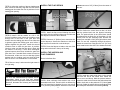
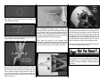
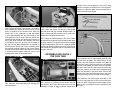
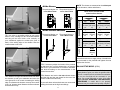
❏ 2. With the wing attached to the fuselage, all parts
of the model installed (ready to fly) and an empty
fuel tank, place the model upside-down on a Great
Planes CG Machine, or lift it upside-down at the
balance point you marked.
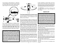
❏ 3. If the tail drops, the model is “tail heavy.” If the
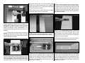
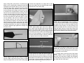
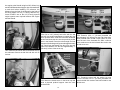
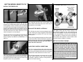
❏ 1. If using a Great Planes C.G. Machine, set the
rulers to 6-3/8" [162mm]. If not using a C.G. Machine,
use a fine-point felt tip pen to mark lines on the top of
the wing on both sides of the fuselage 6-3/8" [162mm]
back from the leading edge. Apply narrow (1/16"
[2mm]) strips of tape over the lines so you will be able
to feel them when lifting the model with your fingers.
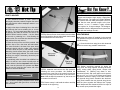
This is where your model should balance for the
first flights. Later, you may experiment by shifting
the C.G. 1/4” [6.4mm] forward or 1/4” [6.4mm] back
to change the flying characteristics. Moving the C.G.
forward will improve the smoothness and stability,
but the model will then be less aerobatic (which
may be fine for less-experienced pilots). Moving
the C.G. aft makes the model more maneuverable
and aerobatic for experienced pilots. In any case,
start at the recommended balance point and
do not at any time balance the model outside the
specified range.
nose drops, the model is “nose heavy.” For a tail heavy
model the receiver battery pack can be moved aft.
For a nose heavy model use Great Planes “stick-on”
lead (GPMQ4485). To find out how much weight is
required, place incrementally increasing amounts of
weight on the bottom of the fuselage over the location
where it would be mounted inside until the model
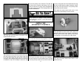
balances. A good place to add stick-on nose weight is
to the firewall. Do not attach weight to the cowl—this
will cause the mounting screws to open up the holes
in the cowl. Once you have determined the amount
of weight required, it can be permanently attached. If
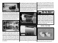
required, tail weight may be added by cutting open the
bottom of the fuse and gluing it permanently inside.
If mounting weight where it may be exposed to fuel or
exhaust, do not rely upon the adhesive on the back
to permanently hold it in place. Over time, fuel and
exhaust residue may soften the adhesive and cause
the weight to fall off. Instead, permanently attach the
weight with glue or screws.
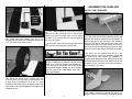
Note: It is highly recommended that with gas powered
planes the ignition system and all its components
be separated from the radio system components by
32
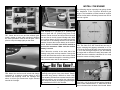
During the last few moments of preparation your
mind may be elsewhere anticipating the excitement
of the first flight. Because of this, you may be more
likely to overlook certain checks and procedures
that should be performed before the model is flown.
To help avoid this, a check list is provided to make
sure these important areas are not overlooked.
Many are covered in the instruction manual, so
where appropriate, refer to the manual for complete
instructions. Be sure to check the items off as they
are completed (that’s why it’s called a check list!).
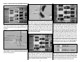
❏ 1. Fuelproof all areas exposed to fuel or exhaust
residue such as the cowl ring, wing saddle area, etc.
❏ 2. Check the C.G. according to the measurements
provided in the manual.
❏ 3. Be certain the battery and receiver are securely
mounted in the fuse. Simply stuffing them into place
with foam rubber is not sufficient.
❏ 4. Extend your receiver antenna and make sure it
has a strain relief inside the fuselage to keep tension
off the solder joint inside the receiver.
❏ 5. Balance your model laterally as explained in
the instructions.
❏ 6. Use threadlocking compound to secure critical
fasteners such as the set screws that hold the wheel
axles to the struts, screws that hold the carburetor
arm (if applicable), engine bolts, etc.
❏ 7. Add a drop of oil to the axles so the wheels will
turn freely.
❏ 8. Make sure all hinges are securely glued
in place.