1
PROGRAMMING MANUAL
Agilent Technologies
Electronic Load Family
Agilent Part No. 06060-90005
Microfiche Part No. 06060-90006
Printed in USA: September, 1991
Update April, 2000
PRINTING HISTORY
The manual printing date and part number indicate the current edition. Reprints between editions will have the same printing
date and may include change pages with corrections or additions to be made to the manual by the user.
New editions of this manual will have a new printing date and, in some cases, may have a new part number. The new edition
will include all changes and corrections made since the previous edition.
Update - April, 2000
Edition 3 - September, 1991
Edition 2 - August, 1989
Edition 1- December, 1988
Copyright 1988, 1989, 1991, 2000 Agilent Technologies, Inc.
This document contains proprietary information which is protected by copyright. All rights are reserved. No part of this
document may be photocopied, reproduced, or translated to another language without the prior consent of Agilent
Technologies. The information contained in this document is subject to change without notice.
SAFETY GUIDELINES
The beginning of the Electronic Load Operating Manual has a Safety Summary Page. Be sure that you are familiar with the
information on that page before programming the electronic load for operation from a controller.
2
CONTENTS
1.
Introduction
Purpose .........................................................................................................................................................7
Documentation .............................................................................................................................................7
Supplied.....................................................................................................................................................7
Recommended ...........................................................................................................................................7
How To Use This Guide..................................................................................................................................8
What You Should Already Know....................................................................................................................8
GPIB Capabilities of The Electronic Load ......................................................................................................8
2.
Introduction To HPSL
What is HPSL? ...........................................................................................................................................11
HPSL Statements........................................................................................................................................11
Simple Command Statements..................................................................................................................11
Compound Command Statements............................................................................................................11
Simple Command Queries.......................................................................................................................11
Compound Command Queries ................................................................................................................12
HPSL Keywords.........................................................................................................................................12
Forms of Keywords .................................................................................................................................12
Keyword Conventions .............................................................................................................................12
Keyword Parameters ...............................................................................................................................13
Numerical Data Formats.......................................................................................................................13
Numerical Data Suffixes and Multipliers .............................................................................................13
Numerical Data Conventions................................................................................................................14
Character Data Formats ........................................................................................................................14
Character Data Conventions .................................................................................................................14
Separators and Terminators .....................................................................................................................14
Data Separators ....................................................................................................................................14
Keyword Separators .............................................................................................................................14
Program Line Terminators ...................................................................................................................15
Common Commands ..................................................................................................................................15
3.
Introduction To Programming
Types of Commands and Queries...............................................................................................................17
Understanding The Command Tree............................................................................................................17
Understanding a Typical Branch ................................................................................................................17
Traversing the RESistance Branch..........................................................................................................18
Using the NRf+ Format ...........................................................................................................................19
Traversing The Command Tree..................................................................................................................20
Use of the Colon......................................................................................................................................20
Use of the Semicolon...............................................................................................................................20
Getting Back to the Root .........................................................................................................................21
Implied Keywords ...................................................................................................................................22
HPSL Queries..........................................................................................................................................23
HPSL Compatibility ...................................................................................................................................23
The SOURce Implied Keyword ..............................................................................................................23
Aliases .....................................................................................................................................................23
Value Coupling...........................................................................................................................................23
Common Commands ..................................................................................................................................24
Programming Examples .............................................................................................................................24
Battery Testing ........................................................................................................................................24
Power Supply Testing..............................................................................................................................24
3
CONTENTS (continued)
4.
4
Language Dictionary
Introduction ................................................................................................................................................29
Keywords ................................................................................................................................................29
Parameters ...............................................................................................................................................29
Related Commands..................................................................................................................................29
Order of Presentation .................................................................................................................................29
Common Commands ..................................................................................................................................30
Introduction .............................................................................................................................................30
Order of Presentation ..............................................................................................................................30
*CLS........................................................................................................................................................30
Syntax Diagram.......................................................................................................................................31
*ESE........................................................................................................................................................32
*ESR?......................................................................................................................................................32
*IDN? ......................................................................................................................................................33
*OPC .......................................................................................................................................................33
*OPC? .....................................................................................................................................................34
*OPT? .....................................................................................................................................................34
*PSC........................................................................................................................................................35
*RCL .......................................................................................................................................................35
*RDT? .....................................................................................................................................................36
*RST .......................................................................................................................................................36
*SAV.......................................................................................................................................................37
*SRE .......................................................................................................................................................37
*STB?......................................................................................................................................................38
*TRG.......................................................................................................................................................38
*TST? ......................................................................................................................................................39
*WAI.......................................................................................................................................................39
Root-Level Commands...............................................................................................................................40
Introduction .............................................................................................................................................40
Tree Diagram...........................................................................................................................................40
ABORt........................................................................................................................................................41
CHANnel....................................................................................................................................................41
Current Subsystem......................................................................................................................................42
Syntax Diagram.......................................................................................................................................43
CURR[:LEVel].......................................................................................................................................44
CURR:PROTection ................................................................................................................................45
CURR:RANGe........................................................................................................................................46
CURR:SLEW .........................................................................................................................................47
CURR:TLEVel.......................................................................................................................................48
Input Subsystem .........................................................................................................................................49
Syntax Diagram.......................................................................................................................................49
INP:PROT:CLEar ..................................................................................................................................50
INP:SHORt ............................................................................................................................................50
INP[:STATe] ..........................................................................................................................................51
MEASure....................................................................................................................................................51
MODE ........................................................................................................................................................52
PORT0 .......................................................................................................................................................53
Resistance Subsystem.................................................................................................................................54
Syntax Diagram......................................................................................................................................55
RES[:LEVel] ...........................................................................................................................................55
RES:RANGe ...........................................................................................................................................57
CONTENTS (continued)
RES:TLEVel ...........................................................................................................................................58
Status Subsystem........................................................................................................................................59
Syntax Diagram.......................................................................................................................................60
STAT:CHANnel......................................................................................................................................61
STAT:CSUMmary ..................................................................................................................................62
STAT:OPERation....................................................................................................................................63
STAT:QUEStionable ..............................................................................................................................65
SYST:ERRor? .........................................................................................................................................66
Transient Subsystem...................................................................................................................................66
Syntax Diagram......................................................................................................................................68
TRAN:DCYCle ......................................................................................................................................69
TRAN:FREQuency ................................................................................................................................69
TRAN:MODE .........................................................................................................................................70
TRAN[: STATe] .....................................................................................................................................71
TRAN:TWIDth .......................................................................................................................................71
Trigger Subsystem......................................................................................................................................72
Syntax Diagram.......................................................................................................................................73
TRIG[: IMMediate] .................................................................................................................................73
TRIG:SOURce ........................................................................................................................................74
TRlG:TlMer ............................................................................................................................................75
Voltage Subsystem .....................................................................................................................................75
Syntax Diagram.......................................................................................................................................76
VOLT[: LEVel].......................................................................................................................................76
VOLT: SLEW .........................................................................................................................................77
VOLT: TLEVel .......................................................................................................................................78
Command and Parameter Summary ...........................................................................................................79
Error Messages ...........................................................................................................................................79
Hardware Errors During Turn-On Selftest.. ............................................................................................79
Hardware Errors During Operation .........................................................................................................79
5.
Status Reporting
General Register Model..............................................................................................................................83
Channel Status............................................................................................................................................83
Channel Summary ......................................................................................................................................85
Questionable Status ....................................................................................................................................86
Output Queue .............................................................................................................................................87
Standard Event Status.................................................................................................................................87
Operation Status .........................................................................................................................................88
Status Byte Register ...................................................................................................................................89
Service Request Enable Register ................................................................................................................89
INDEX........................................................................................................................................................... 91
Agilent Sales and Support Offices ....................................................................................................... 96
5
1
Introduction
Purpose
The purpose of this guide is to enable you to use HPSL commands to remotely control your Agilent Technologies electronic
load from a controller using HPSL programming language. It is assumed that the following has been done:
•
The electronic load has been installed and is operating normally from its front panel.
•
The controller has been connected to the electronic load and the electronic load’s GPIB address has been set.
Note
The electronic load GPIB address cannot be set by program. It must be set from the front panel of the
electronic load (refer to the Installation chapter of your electronic load Operating Manual).
Documentation
Important
Read your electronic load Operating Manual before using this guide.
Supplied
Every Electronic Load comes with the following documentation:
Operating Manual
Installation and Basic Operating Instructions, including local front-panel operation. Be
sure to read that document first.
Programming Reference
Guide
This guide for remote operation from a controller.
Recommended
The following reference documents are recommended:
•
1
Tutorial Description of the General Purpose Interface Bus
Highly recommended for those not experienced with IEEE 488.1 and 488.2.
•
2
ANSI/IEEE Standard 488.2-1987
The source document for programming via IEEE 488.1 and IEEE 488.2.
1
Contact your local Agilent Sales office
Contact Institute of Electrical and Electronics Engineers, 345 E. 47 Street. New York, NY 10017, USA
2
Introduction
7
How To Use This Guide
Chapter
2 - Introduction to HPSL
Synopsis
The basics of HPSL to help you understand the terminology and diagrams in
Chapter 4.
3 - Introduction to Programming
How to understand the command tree diagram and construct typical operating
programs.
4 - Language Dictionary
An alphabetically ordered description of all electronic load HPSL commands.
5 - Status Reporting
An explanation of how the electronic load status registers are affected by the
HPSL programming statements.
Index
What You Should Already Know
This guide does not assume that you know anything about HPSL or are a programmer. It is assumed that you do know:
•
the basics of the General Purpose Interface Bus (GPIB).
•
how to send and receive ASCII data to and from a GPIB instrument (or where, in your computer and GPIB interface
documentation, to find instructions to do this).
•
how to incorporate the HPSL statements as ASCII strings within output and input statements of the programming
language you are using.
•
the basic operating principles of the electronic load as explained in Chapters 2 and 5 of your electronic load Operating
Manual.
GPIB Capabilities Of The Electronic Load
The GPIB capabilities of a typical electronic load are listed in Table 1 -1.
Note
8
Refer to the General Information chapter of your electronic load Operating Manual for its exact
capabilities.
Introduction
GPIB Capabilities
Table 1-1. GPIB Capabilities of Electronic Loads
Response
Interface
Function
Talker/Listener
All electronic load functions except for setting the GPIB address are
programmable over the GPIB. The electronic load can send and receive
messages over the GPIB. Status information is sent using a serial poll. Front
panel annunciators indicate the present GPIB state of the electronic load.
AH1, SH1, T6. L4
Service Request
The electronic load sets the SRQ line true if there is an enabled service
request condition. Refer to Chapter 5 - Status Reporting for more
information.
SR1
Remote/Local
In local mode, the electronic load is controlled from the front panel but will
also execute commands sent over the GPIB. The electronic load powers up
in local mode and remains in local mode until it receives a command over
the GPIB. Once the electronic load is in remote mode the front panel RMT
annunciator is on, all front panel keys (except
) are disabled, and the
display is in normal metering mode. Pressing
on the front panel
returns the electronic load to local mode.
can be disabled using
local lockout so that only the controller or the power switch can return the
electronic load to local mode.
RL1
Device Trigger
The electronic load will respond to device trigger function.
DT1
Device Clear
The electronic load responds to the Device Clear (DCL) and Selected
Device Clear (SDC) interface commands. They cause the electronic load to
clear any activity that would prevent it from receiving and executing a new
command (including *WAI and *OPC?). DCL and SDC do not change
any programmed settings.
DCL, SDC
Introduction
9
2
Introduction To HPSL
What Is HPSL?
HPSL is a system programming language developed by Agilent Technologies for controlling instrument functions. HPSL is
intended to function with standard GPIB hardware. HPSL conforms to the IEEE 488.2 Standard Digital Interface for
Programmable Instrumentation. This standard provides codes, formats, protocols, and common commands not defined in
the original IEEE 488.1 standards. Unless you intend to do some very intricate programming, you need not be expert in the
IEEE 488.2 standard, although it is a good reference document to have available.
Note
TMSL (Test and Measurement Systems Language) is a later version of HPSL that has been made
available outside of Agilent Technologies for industry use. Although it is very similar, the HPSL used in
the electronic loads may not be totally compatible with TMSL.
HPSL Statements
HPSL statements are instrument control commands and queries. A command statement sends an instruction to the electronic
load and a command query requests information from the electronic load.
Simple Command Statements
The simplest command statement consists of a command, or keyword, usually followed by a parameter or data:
VOLT 25
CURR 50
TRIG
Simple command statements
Compound Command Statements
When two or more keywords are connected by colons (2:), it creates a compound command statement. The last keyword
usually is followed by a parameter or data.
VOLT:SLEW 1000
CURR:RANG 6
TRIG:SOUR BUS
Compound common statements
Simple Command Queries
The simplest command query consists of a keyword followed by a question mark:
VOLT?
Simple command queries
CURR? CHAN?
Introduction to HPSL 11
Compound Command Queries
When two or more keywords are connected by colons and followed by a question mark, it creates a compound query
statement.
VOLT:TRIG? Compound command queries
CURR:PROT? MEAS:POW?
HPSL Keywords
Keywords (also known as “Instrument Control Headers”) are recognized by the electronic load's decoder, or “parser”. Each
keyword is intended to be descriptive of the statement function. Refer to Figure 4-2 in Chapter 4 - Language Dictionary for
a quick look at all the electronic load keywords.
Forms of Keywords
Every keyword has two forms:
Long Form
The word is spelled out completely to identify its function. STATUS, RESISTANCE, and TRIGGER are
long form keywords.
Short Form
The word contains only the first three or four letters of the long form. STAT, RES, and TRIG are short
form keywords.
Short forms are constructed according to the following rules:
• If the keyword consists of four or fewer letters
then all the letters are used
•
If the keyword consists of five or more letters
and the fourth letter IS NOT a vowel (a,e.i,o,u)
•
then the first four letters are used
Note
•
and the fourth letter is a vowel
then only the first three letters are used
The short form provides the fastest program execution.
Keyword Conventions
In keyword definitions and diagrams in this guide, the short form part of each keyword is emphasized in boldface UPPERCASE letters to help you remember it.
•
•
•
•
TRlGger
IMMediate
RESistance
SHORt
The HPSL parser (decoder) is not sensitive to case. It will accept Trig, trig, trigger, TRIGGER, triGgER, etc. Regardless of
which form you use, you must spell out all the letters. For example, RESI or TRI will not be recognized.
12
Introduction to HPSL
Keyword Parameters
Parameters are data values that the parser expects to find after certain keywords. All data programmed to or returned from
the electronic load is ASCII. The data may be numerical data or character strings. HPSL uses the parameter forms in
Section 7 of IEEE 488.2 Standard Digital Interface for Programmable Instrumentation with the additions described here.
Numerical Data Formats HPSL accepts the first four numerical data types listed in Table 2-1 and described in Section 7
of IEEE 488. 2 Standard Digital Interface for Programmable Instrumentation. In addition, HPSL recognizes an expanded
form of decimal numeric value known as < NRf > . This allows the characters MIN and MAX to be entered for the minimum
and maximum values that the parameter can be set to under the existing operating conditions.
Symbol
NR1
Table 2-1. Numerical Data Formats
Data Form
Digits with no decimal point. The decimal point is assumed to be to the right of the least-significant
digit. For example, 273, 0273
NR2
Digits with a decimal point. E.g.,273., 27.3, .0273
NR3
Digits with a decimal point and an exponent. E.g., 2.73E+2, 2.73E-2
NRf
Flexible decimal form that induces NR1 or NR2 or NR3. E.g., 273, 27.3, 2.73E+2
NRf +
Expanded decimal form that includes NRf and MIN,MAX. E.g., 273, 27.3, 2.73E-2, MIN, MAX. MIN
and MAX are the minimum and maximum limit values for the parameter and are implicit in the range
specification for the parameter.
Numerical Data Suffixes and Multipliers. Numeric data may be followed by a suffix that dimensions the data. A suffix
may be preceded by a multiplier. Section 7 of IEEE 488.2 Standard Digital Interface for Programmable Instrumentation
describes the approved data suffixes and multipliers. Where no suffix is entered, the dimension is implied by the syntax of
the command. The electronic loads make use of the suffixes and multipliers listed in Table 2-2 and Table 2-3. Note the
special consideration given to the multiplier for mega. In most cases, mega is represented by MA. However, there are
exceptions made for megahertz (MHZ) and megohm (MOHM). In only these two cases, M is understood to be lE + 6. Do not
confuse the mega multiplier MA with the combination suffix and multiplier MA, which represents milliamperes (lE-3).
Class
Current
Frequency
Resistance
Time
Amplitude
Power
Slew Rate
Table 2-2. Suffix Elements
Preferred
Secondary
Suffix
Suffix
A
Hz
MHZ
OHM
MOHM
s
V
W
A/s
V/s
Referenced
Unit
Ampere
Hertz
Megahertz
ohm
Megohm
Second
Volt
Watt
Amperes/Second
Volts/Second
Introduction to HPSL 13
Multiplier
1E6
1E3
1E-3
1E-6
1E-9
Note
Table 2-3. Most-Used Suffix Multipliers
Mnemonic
Definition
MA
mega
K
kilo
M
milli
U
micro
N
nano
You may construct compound suffixes of multipliers and elements. For example: 1 KHz for 1000 Hz;
1 A/µs for 1000000 A/s.
Numerical Data Conventions. In this guide, numerical data types are shown in emphasized text within angle brackets,
such as < NR1 > or < NRf > . On drawings, numerical data appears within boxes
.
. The brackets around the suffix indicate that the entry is
Data suffixes are shown inside brackets within boxes
optional. That is because there is a default suffix for the data that accompanies each command.
Character Data Formats. For command statements, the < NRF + > data format permits entry of required characters. For
query statements, character strings may be returned in either of the forms shown in Table 2-4, depending on the length of
the returned string.
Symbol
crd
aard
Table 2-4. Query Character String Formats
Character Form
Character Response Data. Permits the return of up to 12 characters.
Arbitrary ASCII Response Data. Permits the return of undelimited 7-bit ASCII. This data
type is an implied message terminator (refer to “Separators and Terminators”).
Character Data Conventions. In this guide, character string parameters are emphasized similar to keywords, such as ON,
OFF, and CONTinuos. This applies both to text and drawings.
Separators and Terminators
In addition to keywords and parameters, HPSL program statements require the following:
Data Separators. Data must be separated from the previous command keyword by a space. This is shown in examples as a
space (VOLT 25) and on diagrams by the letters SP inside a circle.
Keyword Separators. Keywords (or headers) are separated by a colon (:), a semicolon (;), or both. For example:
•
•
•
INP:SHOR
MEAS:CURR?;VOLT?
CURR 25;:VOLT 50
Important
14
Proper use of the (:) and the (;) is very important to the construction of command messages. This is
explained in Chapter 3 - Introduction to Programming .
Introduction to HPSL
Program Line Terminators. A terminator informs HPSL that it has reached the end of a statement. Normally, this is sent
automatically by your GPIB programming statements. The termination also occurs with other terminator codes, such as
EOI. In this guide, the terminator is assumed at the end of each example line of code. If it needs to be indicated, it is shown
by the symbol < nl >, which stands for “new line”' and represents the ASCII coded byte 0A hexadecimal (or l0 decimal).
Common Commands
Common statements are not derived from HPSL but are generic commands and queries defined by the IEEE 488.2 standard.
The following examples are common statements:
•
•
•
*RST
*IDN?
*TRG
Common statements are executed independently of HPSL statements. Their relationship to HPSL statements is described
more fully in “Chapter 3”. The function of each common statement is summarized in Chapter 4 - Language Dictionary and
fully described in Section 10 of IEEE 488.2 Standard Digital Interface for Programmable Instrumentation.
Introduction to HPSL 15
3
Introduction To Programming
Types Of Commands and Queries
The electronic load responds to two types of commands and queries, Common and Root. Common commands were
introduced in Chapter 2-Introduction to HPSL and are relatively simple to use. The root commands are organized in a
hierarchy that is best shown via a command tree diagram.
Understanding The Command Tree
Figure 4-2 in Chapter 4-Language Dictionary is a tree diagram of all the root commands for the electronic load. Notice the
following:
•
The originating point of the diagram is at the root. In this case, the diagram resembles an inverted tree. "Root" is not a
command, but the origin for all commands.
•
The root divides into two major branches-Channel-Specific commands and Channel-Independent commands. Both
types are accepted by all electronic loads.
•
Each major branch divides into several branches. The CURRent commands are a branch. The VOLTage commands
are another branch. So are the TRlGger commands.
•
Some keywords are within brackets [ ]. These are implied keywords. Implied keywords are optional, but you may want
to use them in certain situations (See Implied Keywords, later in this chapter).
Note
•
For fastest program execution, omit implied keywords.
Commands followed by ? are queries. They cause the electronic load to store information in its output buffer from
where it can be read by the controller over the GPIB.
Understanding A Typical Branch
Here are the keywords for the RESistance branch as they appear in Chapter 4-Language Dictionary:
Command and Function
RESistance[:LEVel][:IMMediate]
Specify input resistance for RESistance mode
RESistance[:LEVel]:TRlGgered
Preset input resistance level pending trigger occurrence
RESistance:RANGe
Specify full-scale resistance input range
RESistance:TLEVel
Specify resistance level for TRANsient function
Introduction To Programming 17
Note
Ignore the meanings of these commands for now. All keywords are defined in the Language Dictionary
and command functions are explained in the electronic load Operating Manual.
Figure 3-1 shows the RESistance commands, which form a typical branch that forms a ’’subtree" of its own. You can see
that the RESistance branch has three subbranches; LEVel, RANGe, and TLEVel. When it reaches the end of a branch, the
parser expects a parameter, a question mark (that identifies the keyword as a query), a semicolon or semicolon-colon
combination, or an end-of-line terminator.
.
Figure 3-1. RESistance Branch Subtree
Figure 3-2 is the syntax diagram for the RESistance branch. You can still identify the tree structure, although it runs from
left-to-right instead of from top-to-bottom. Note the following symbols that were discussed in Chapter 2-Introduction to
HPSL.
•
Keywords with the short form shown in bold-faced capital letters. Implied keywords are not within brackets in
diagrams.
•
Spaces shown as "SP" within circles.
•
Boxes showing the form (NRf + ) of the parameter.
•
Boxes showing optional suffixes. Multipliers are not shown.
•
Question marks that convert a command into a query
•
Colons (:) that precede each keyword. They are important and are discussed later in more detail.
Traversing The RESistance Branch
From Figure 3-2 note that there are two implied keywords that you can usually ignore. This makes two of the commands
very simple. If you enter:
RES 1.5
you will send the electronic load an immediate resistance level command. The command actually is:
RES:LEV:IMM 1.5
18
Introduction To Programming
but the parser assumes that the two implied keywords are there. For the same reason, you can query the immediate
resistance value with:
RES?
Note
When sending a query, do not enter a space between the keyword and the question mark.
The newline character < nl > or EOI terminator sends the parser back to the root level. Many controllers automatically send
this character at the end of each program output string. To program the resistance range and the TLEVel value, you could
send:
RES:RANG 1000 < nl >
RES :TLEV 5000 < nl >
Note
There is an alternate way to do this, which is shown under ''Traversing the Command Tree.”’
Figure 3-2. RESistance Branch Syntax Diagram
Using the NRf+ Format
Referring to Figure 3-2, note that all parameters are of the <NRf+ > type. This allows you to easily set a numeric parameter
to its maximum or minimum value. If you wanted to increase the immediate resistance of the presently selected range to its
maximum value, you could send:
Introduction To Programming 19
RES MAX < nl >
Note
MAX and MIN are the maximum and minimum values allowed in the present operating mode of the
electronic load. For the electronic load this generally means the limits within the present range.
MAX and MIN may also be used with queries to find the maximum and minimum permitted settings of the present mode.
For example:
RES? MAX
Returns the maximum permitted value of the present range
Traversing The Command Tree
Note
The HPSL parser traverses the command tree as described in Appendix A of IEEE 488.2 Standard
Digital Interface for Programmable Instrumentation . The Enhanced Tree Walking Implementation
given in that appendix is not implemented in HPSL . The simplified explanation given here is sufficient
for using the electronic load command set in most applications.
Use of the Colon
When you examined the RESistance branch, you noticed the colon (:) that separated keywords from each other. A colon
represents a change in branch level. ROOT is the highest level. Whenever you enter a (:), the parser expects it to be
followed by a command of the next lower level. For example:
INP:PROT:CLE
CURR:LEV:TRIG
Note
INP and CURR are root-level commands. PROT and LEV are first branches, and CLE and
TRIG are second branches. Each (:) instructs the parser to move down to the next branch.
A colon after a keyword always moves the parser down, never up the command tree.
If you enter INP:PROT:CLE:, you will get an error because the parser expects to find another keyword after the last (:). In
this example, you will also get an error if you enter INP:PROT because another keyword is required after PROT.
However, a command like MODE:RES is o.k. because no keyword or parameter is expected after RES. You will know
what is required in each case by referring to the Language Dictionary.
Use of the Semicolon
The semicolon (;) is a "back-up" command. It instructs the parser to return to the previous colon. Figure 3-3 illustrates how
the semicolon moves the parser backwards.
Note
The semicolon by itself can back the parser up to a colon only within the same branch.
The semicolon allows you to combine command statements on one line to create command messages.
VOLT:SLEW 5000 < nl > Statements are on separate lines
VOLT:TLEV 55 < nl >
VOLT: SLEW 5000;TLEV 55 < nl > Combined statements form a message
20
Introduction To Programming
Figure 3-3. What the Semicolon Does
Note
There is no single command to move the parser back two colons. In example a above, backing up from
Level 2 to Level 1 requires a return to the root.
Getting Back to the Root
To go from a command in one branch to a command in another branch, you must first return to the root. You can do this by:
■
entering a new-line character. This is symbolized by (<nl>) and can be any control character that starts a new line, such
as:
■
linefeed (LF).
■
an end-of-line (EOI).
■
entering a semicolon followed by a colon (;:). This instructs the parser to return to the root.
Looking at Figure 4-2 in the Language Dictionary, suppose you wanted to set two trigger levels; the CURRent level to 15.5
and the VOLTage level to 25.5. Either of the following commands would do this.
CURR:TRIG 15.5 < nl >
VOLT:TRlG 25.5 < nl >
or
CURR:TRIG 15.5;:VOLT:TRlG 25.5 < nl >
Similarly, the following query would return the present values of current, power, and voltage and the state of the output port.
MEAS:CURR?;POW?;VOLT?;:PORT0? < nl >
Note The < nl > notation is assumed and will be omitted in later programming examples.
Introduction To Programming 21
Figure 3-4. Returning the Parser to the Root
Implied Keywords
Keywords shown within brackets, such as CURR[:LEVel], are implied keywords. If they are omitted, the parser will
execute them automatically.
How to Use Implied Keywords. Because [LEVel] is an implied keyword, the parser regards the following two commands
as the same:
CURR:LEV 30
CURR 30
Under most circumstances, implied keywords are optional and you may omit them as in the above example. Sometimes you
may choose to use them in order to make the semicolon move the parser in the desired way. Returning to our previous
keyword diagram under Figure 3-2, note that you can set the immediate resistance value with:
RES .5
The parser automatically assumes that you want to program LEVel. If you wanted to program both LEV and TLEVel in
one program line and sent:
RES .5:TLEV 1
Incorrect parser positioning
the parser would end up back at the root and you would get an error because there is no TLEVel command at the root. The
correct statement would be:
RES:LEV .5;TLEV 1
or
RES .5;RES:TLEV 1
22
Correct parser positioning
Introduction To Programming
By inserting the implied keyword in RES:LEV .5; you allowed the parser to interpret the (;) as a command to move back to
the branch containing RANG and TLEV. Without LEV in the command, the parser would "find" only RES, CURR, STAT
or other root-level commands.
HPSL Queries
You can program more than one query in a single line such as:
CURR?;RES?;VOLT?
Return present values of programmed current, resistance, and voltage ,
However, observe the following precautions:
■
You must read back the results of the queries before sending another command line to the electronic load. Otherwise, a
Query Interrupted error will occur and the returned data will be lost.
■
Multiple queries must be separated by semicolons and some controllers may have problems interpreting this format. In
this case, you must enter each query and its corresponding readback on a separate line.
HPSL Compatibility
The SOURce Implied Keyword
Referring to Figure 4-2 in the Language Dictionary, note that several of the Channel-Specific branches include the implied
keyword [SOURce]. It is there to make electronic load programs compatible with other HPSL devices. Although the
electronic load will accept it, you can omit [SOURce] and consider the Channel-Specific branch as connected directly to the
root.
Aliases
Looking at Figure 4-2 you will notice that some electronic load commands will accept two keywords that perform the
identical function. For example:
MODE|FUNCtion
Examples of two commands that do the same thing
INPut|OUTPut
CHANnel|INSTrument
These alternate keywords are called "aliases" and are supported by the electronic load in order to make it compatible with
other HPSL instruments.
Value Coupling
When you program, you must be aware of the effect known as value coupling. Value coupling results when a command
directed toward one parameter changes the value of another parameter. For example, the CURRent branch includes the
following keywords:
Command
CURRent[:LEVel][:IMMediate]
CURRent:RANGe
CURRent:TLEVel
There is value coupling among the RANge, LEVel, and TLEVel commands. If a previously programmed LEVel value is
outside a particular range, then changing to that range will affect the value of LEVel. There are several instances of value
coupling among the electronic load commands and you should always check a command’s description in theLanguage
Dictionary to determine if it is value coupled to another command.
Introduction To Programming 23
Common Commands
Common commands, while not part of the command tree, can be mixed in with regular commands. The electronic load
responds to the Common commands and queries listed in Figure 4-1 of the Language Dictionary. You can mix Common
commands in with regular programming statements; the Common command will be executed without affecting the position
of the parser.
Programming Examples
The following programming examples are practical applications of the electronic load. Although they are in HP Series 300
Basic, the principles can be applied to any other version of BASIC or even to another language.
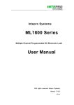
Battery Testing
The principal measurement of a battery’s performance is its rated capacity. The capacity of a fully charged battery, at a fixed
temperature, is defined as the product of the rated discharge current in amperes and the discharge time in hours, to a
specified minimum termination voltage in volts (see Figure 3-5). A battery is considered completely discharged when it
reaches the specified minimum voltage called the "end of discharge voltage" (EODV).
Figure 3-5. Typical Discharge Curve
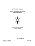
In this example, the electronic load discharges three nickel-cadmium batteries to determine their discharge rates at a fixed
temperature (see Figure 3-6). The batteries are connected in series so that when the EODV is reached, it is still above the
minimum operating voltage of the electronic load. The EODV for nickel-cadmium batteries is typically 1.0 volts.
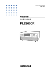
Power Supply Testing
A typical use for electronic loads when testing power supplies involves power supply burn-in. One of the problems
associated with burn-in is what to do if the power supply fails before the test is over. One solution involves continuously
monitoring the supply and removing the load if the supply fails during the test (see Figure 3-7).
24
Introduction To Programming
Figure 3-6. Batteries in Series
In this example, the Electronic Load is used to burn-in a power supply at its rated output current. Because the Electronic
Load is operating in CC mode, if the power supply’s output current drops below the rated output current during the test, the
UNR (unregulated) condition will be set on the Electronic Load. This can be used to indicate that a failure has occurred on
the power supply. If the unregulated condition persists for a specified time, the inputs of the Electronic Load are turned off.
The purpose of this example is not to illustrate power supply testing, but to explain how to program and use the status
registers on the Electronic Load. The part of the program that runs the test simply monitors the supply at the rated output
current for one hour and stops the test. You can replace this portion of the program with your own routine to test the power
supply. Although SRQ (service request) is enabled to interrupt only on the UNR bit in this example, you can modify the
program to interrupt on other conditions.
Figure 3-7. Typical Burn-In Test
Introduction To Programming 25
Battery Test Example Program
l0
20
30
40
50
60
70
80
90
l00
110
120
130
140
150
160
170
180
190
200
210
220
230
240
250
260
270
280
290
300
26
! Battery Test Example Program
!
Eodv=l.0
! End of discharge voltage for single cell
Number_of_cells=3
! Number of cells to be discharged in series
Discharge_at .05
! Constant current discharge rate in amperes
!
OUTPUT 705;"INPUT OFF"
! Disables the inputs
OUTPUT 705;"MODE:CURRENT"
! Sets CC mode
OUTPUT 705;"CURRENT:LEVEL";Discharge_at
! Sets the CC level
OUTPUT 705;"INPUT ON"
! Enables the inputs
!
Start_time=TIMEDATE
! Records test start time
!
Start_test:
! Starts test routine that
OUTPUT 705;"MEASURE:VOLTAGE?"
! continuously measures and reads
ENTER 705;Sum_of_volts
! back the voltage and current
OUTPUT 705;"MEASURE:CURRENT?"
! until batteries are completely
ENTER 705;Actual_current
! discharged
!
PRINT "Total cell voltage: ";Sum_of_volts
PRINT "Actual current: ";Actual_current
PRINT "Elapsed time in seconds: ";TIMEDATE-Start_time
!
IF Sum_of_volts>(Number_of_cells*Eodv) THEN GOTO Start_test
! Checks if the total voltage is less than the
! sum of the minimum cell voltages of all cells
!
OUTPUT 705;"INPUT OFF"
! Disables the inputs
!
END
Introduction To Programming
Power Supply Test Example Program
l0
20
30
40
50
60
70
80
90
l00
110
120
130
140
l50
160
170
180
190
200
210
220
230
240
250
260
270
280
290
300
310
320
330
340
350
360
370
380
390
400
410
420
430
440
450
460
470
480
490
500
! Power Supply Test Example Program
!
Current=10
! Load current in amperes
Burn_in_time=36000
! One hour burn-in time
!
ON INTR 7 GOSUB Srq_service
! Set up interrupt linkage
ENABLE INTR 7;2
! Enable interrupts for SRQs
!
OUTPUT 705;"INPUT OFF"
! Disables the inputs
OUTPUT 705;"*SRE 4"
! Enable SRQ (SRQ enable)
OUTPUT 705;"STAT:CSUM:ENAB 2"
! Enable Chan 1 (channel summary)
OUTPUT 705;"STAT:CHAN:ENAB l024"
! Enable UNR bit (channel status)
OUTPUT 705;"MODE:CURRENT"
! Sets CC mode
OUTPUT 705;"CURRENT:LEVEL";Current
! Sets the CC level
OUTPUT 705;"INPUT ON"
! Enables the inputs
!
PRINT "Burn-in test started at ";TIME$(TIMEDATE)
!
FOR I=1 TO Burn_in_time
! Loop on wait You can write your
WAIT .1
! own power supply test routine and
NEXT I
! insert it in this section
!
OUTPUT 705;"INPUT OFF"
! Disables the inputs at end of test
PRINT "Burn-in test complete at ";TIME$(TIMEDATE)
STOP
!
Srq_service
! Service request subroutine
Load_status=SPOLL(705)
! Conduct serial poll
IF BIT(Load_status, 6) THEN
! Check if SRQ bit is set
GOSUB Check_unr
ELSE
PRINT "A condition other than UNR generated SRQ at ";TIME$(TIMEDATE)
END IF
! You can also check the other bits
ENABLE INTR 7
! Re-enable interrupts before return
RETURN
!
Check_unr
! Check if UNR bit still set
WAIT 1
! Wait 1 s before reading UNR bit
OUTPUT 705;"STAT:CHAN:COND?"
! Read channel condition register
ENTER 705;Value
IF Bit(Value, l0)=0 THEN
! Return value for UNR bit only
OUTPUT 705;"*CLS"
! If 0, clear channel event register
PRINT "UNR was momentarily asserted at ";TIME$(TIMEDATE)
ELSE
OUTPUT 705;"INPUT OFF"
! Disables the inputs
PRINT "UNR is asserted at ";TIME$(TIMEDATE);" Inputs are turned off"
STOP
END IF
RETURN
END
Introduction To Programming 27
4
Language Dictionary
Introduction
This section gives the syntax and parameters for all the IEEE 488.2 common commands and HPSL commands used by the
electronic loads. It is assumed that you are familiar with the material in Chapters 2 and 3, which explain the terms, symbols,
and syntactical structures used here and provide an introduction to programming. You should also be familiar with the
Operation Overview and Remote Operation chapters in the electronic load Operating Manual that was shipped with the
electronic load. Those chapters explain how the electronic load functions and how to write simple programs to perform
basic functions from a controller.
Because the versatility of HPSL allows such freedom in programming, the programming examples show just simple
applications of the commands. With experience, you will find ways of combining simple statements into more complex
compound ones, or forming iterations within compound statements. Because HPSL functions are the same in all electronic
loads, the examples in this chapter are generic. If you send a command or query in a manner consistent with the syntax of
your programming language, then the statement or query will always perform the specified function.
Keywords
Keyword explanations use the “long form” of the word, but the short form is used in the examples. If you have any concern
that the meaning of a keyword in your program listing will not be obvious at some later time, then use the long form to help
make your program self-documenting.
Parameters
Most commands require a parameter and most queries will return a parameter. The range for a parameter may vary
according to the model of electronic load. For consistency, the examples and explanations use parameters for the Model
Agilent 6060A Electronic Load. However, these examples and explanations are valid for any electronic load. Parameters for
all current models can be found in Table 4-1 at the end of this chapter.
Related Commands
Where appropriate, related commands or queries are included. These are listed either because they are directly related by
function or because reading about them will clarify or enhance your understanding of the original command or query.
Order Of Presentation
All the electronic loads commands and queries are included in this dictionary. The dictionary is organized as follows:
•
•
IEEE 488.2 common commands, in alphabetical order.
Root level commands, in alphabetical order. These consist of:
Single commands.
Subsystems. The individual commands for a subsystem are listed in alphabetical order under the
subsystem.
Language Dictionary 29
Common Commands
Introduction
Common commands are defined by the IEEE 488.2 standard to perform some of the basic instrument functions, such as
identification, reset, determining how status is read and cleared, and how commands and queries are processed. Common
commands are accepted and processed when they are sent as separate commands and also when they are included within
program messages. Execution of a common command does not change the position of the parser in the program tree but
leaves it in the same place it was before the common command was executed (refer to Chapter 2 -Introduction to HPSL).
This does not mean that a common command has no effect on the rest of a programming message.
The electronic loads respond to the 13 required common commands that control internal operation, synchronization, status
and event registers, and system data. Because they have full trigger capability, the electronic loads also respond to *TRG.
In addition, the electronic loads accept six optional common commands. The description for each common command or
query specifies if it affects status registers. In order to make use of this information, you must refer to Chapter 5 - Status
Reporting, which explains how to read the status registers and use the information that they return.
Order of Presentation
Figure 4-1 shows the common commands and queries, which are presented in alphabetical order. If a command has a
corresponding query that simply returns the data or status specified by the command, then both command and query are
included under the explanation for the command. If a query does not have a corresponding command or is functionally
different from the command, then the query is listed separately.
*CLS
Clear Status Command
Type
Description
Device Status
This command causes the following actions (See Chapter 5 - Status Reporting for
descriptions of all registers):
•
•
•
•
Command Syntax
*CLS
Parameters
None
Query Syntax
30
Clears the following registers without affecting any corresponding Enable registers or
Transition Filters:
Channel Status Event registers for all channels.
Channel Summary Event register.
Questionable Status Event register.
Standard Event Status Event register.
Operation Status Event register.
Clears the Error Queue.
Forces a previously executed *OPC command to appear as if it had been completed.
It does not do this with the *OPC? command. (See *OPC? for more details).
If *CLS immediately follows a program message terminator (<nl>), then the output
queue and the MAV bit are also cleared.
*OPC
Language Dictionary
*OPC?
Syntax Diagram
Figure 4-1. Common Commands Syntax Diagram
Language Dictionary 31
*ESE
Standard Event Status Enable Command/Query
Type
Description
Command Syntax
Parameters
Suffix
Example
Device Status
This command sets the condition of the Standard Event Status Enable register, which
determines which events of the Standard Event Status Event register (see *ESR?) are
allowed to set the ESB (Event Summary Bit) of the Status Byte register. A "1" in the bit
position enables the corresponding event. All of the enabled events of the Standard Event
Status Event register are logically ORed to cause the ESB (bit 5) of the Status Byte
register to be set. See Chapter 5 - Status Reporting for descriptions of all three registers.
*ESE <NRf>
0 to 255
None
*ESE 129
Query Syntax
*ESE?
Returned Parameters
<NR1>
Related Commands
*ESR?
*PSC
Enables the OPC and PON events of the Standard Event Status Event
register.
Value: 0 to 255
*STB?
Standard Event Status Register Query
Type
Description
Device Status
This query reads the Standard Event Status Event register. Reading the register clears it.
See Chapter 5 - Status Reporting for a detailed explanation of this register.
Bit Position
Bit Name
Bit Weight
Query Syntax
*ESR?
Returned Parameters
<NR1>
Suffix
Related Commands
32
Value: 0 to 255
None
*OPC
Language Dictionary
Standard Event Status Event Register
7
6
5
4
3
2
PON
0
CME
EXE
DDE
QYE
128
64
32
16
8
4
*CLS
1
0
2
0
OPC
1
*IDN?
Identification Query
Type
Description
Query Syntax
Returned Parameters
Example
System Interface
This query requests the electronic load to identify itself.
*IDN?
<aard> form consisting of four strings separated by commas. The content of each string
is:
String
Information
Agilent Technologies
Manufacturer
xxxxA
Four-digit model number followed
by a letter suffix
0
Always returns zero
a.xx.xx
Revision level of primary
interface firmware
Agilent Technologies,6060A,0,A.01.02
Electronic
This identifies an Agilent Model 6060A
Load; with primary interface firmware
revision A.01.02
Related Commands
*OPC
*OPT
*RDT?
Operation Complete Event Bit Command
Type
Description
Device Status
This command causes Bit 0 of the Standard Event Status Event register to be set when the
electronic load has completed all pending operations. (See *ESR? for the bit configuration
of this register.) Pending operations are complete when:
•
All previous commands have been executed.
•
Any change in the input level caused by previous commands has been completed.
(Effects of slew rate have been accounted for.)
•
No pending trigger level operations are set for the single electronic load or for any
channel of the multiple electronic load.
*OPC does not prevent processing of subsequent commands but Bit 0 will not be set until
all pending operations are complete.
Command Syntax
Parameters
Related Commands
*OPC
None
*WAI
*OPC?
Language Dictionary 33
*OPC?
Operation Complete Output Query
Type
Description
Device Status
This query causes the electronic load to place an ASCII "1" in the Output Queue when all
pending operations are completed. Pending operations are complete when:
•
All commands that were issued before an *OPC command have been executed.
•
Any change in the input level caused by these previous commands has been
completed. (Effects of slew rate have been accounted for.)
•
No pending trigger level operations are set for the single electronic load or for any
channel of the multiple electronic load.
Unlike *OPC, *OPC? prevents processing of all subsequent commands. When all
pending operations are completed, an ASCII "1" is placed in the Output Queue.
*OPC? is intended to be used at the end of a command line so that the program can then
monitor the bus for data until it receives the "1" from the Output Queue.
Do not follow a :LEV:TRIG command (CURR:TRIG, VOLT:TRIG or RES:TRIG)
with *OPC? unless TRIG:SOUR has been previously set to EXTernal, LINE or TIMer.
These are the only triggers that can be processed after *OPC? TRIG:IMM, *TRG, and
GPIB bus triggers sent after *OPC? will be prevented from executing, stopping system
operation. If this occurs, the only programmable way to restore operation is by sending the
electronic load a GPIB DCL (Device Clear) command.
Command Syntax
*OPC?
Returned Parameters
<NR1>
ASCII 1 is placed in the Output Queue when the electronic load has completed
all pending operations.
*OPC
*TRIG:SOUR
Related Commands
*OPT?
Options Identification Query
Type
Description
Query Syntax
Returned Parameters
Suffix
Related Commands
34
*WAI
Device Status
This query specifies options installed in the multiple electronic load. The query presently
is not supported and returns a zero for all electronic loads.
*OPT?
0
None
*IDN?
Language Dictionary
*RDT?
*PSC
Power-on Status Clear Command/Query
Type
Description
Device Initialization
This command controls the automatic clearing at power turn-on of:
• The Service Request Enable register.
• The Standard Event Status Enable register.
If the command parameter = 0, then the electronic load can be programmed to request
service at turn on. Any non-zero parameter causes both registers to be cleared at turn on,
preventing the electronic load from being capable of requesting service at this time. See
Chapter 5 - Status Reporting for details of these registers.
Command Syntax
Parameters
Suffix
*PSC <NRf>
0 or not zero
None
Query Syntax
*PSC?
Returned Parameters
<NR1>
Suffix
None
Related Commands
None
*RCL
0 = power-on clear flag is false; affected registers not cleared at turn on.
1 = power-on clear flag is true; affected registers cleared at turn on.
Recall Instrument State Command
Type
Description
Device State
This command restores the electronic load to a state that was previously stored in memory
with a *SAV command to the specified location (see *SAV). *RCL also does the
following:
■
Forces an ABORt command before resetting any parameters. (This removes all
pending trigger levels.)
■
After all parameters have been recalled, executes an INP:PROT:CLE to clear the
electronic load’s protection circuits.
■
Sets CAL:MODE to OFF (See the electronic load Operating Manual for the
calibration commands).
■
Sets CHAN to 1 in the multiple electronic load.
At power turn-on, the equivalent of an *RCL 0 is executed to restore the electronic load to
the state stored in location 0. The same state is also set if the *RCL command is directed
to a location where no state was stored since the last time power was cycled.
Note *RCL does not affect any Status Enable registers or Transition Filters.
Language Dictionary 35
Command Syntax
Parameters
*RCL <NRf>
0 through 6 where:
States 1-6
State 0
Suffix
None
Related Commands
*RST
*RDT
Volatile states previously stored by *SAV
Nonvolatile state previously stored by *SAV 0
*SAV
Resource Description Transfer Query
Type
Description
Query Syntax
Returned Parameters
Device Specification
This query returns the model number of a single electronic load or the model number of the
module installed in each channel of a multiple electronic load. For multiple electronic
loads, a semicolon (;) separates each module and the string terminated with a LF (line feed).
*RDT?
<aard> String value as follows:
single electronic load
CHAN1:nnnnL; where “nnnnL” = model number
multiple electronic load
Related Commands
*RST
*IDN?
CHAN <c>:nnnnnL; where “c” = channel number and
“nnnnnL” = number and suffix letter of the module in that
channel.
*OPT?
Reset Command
Type
Description
Device State
This command sets the electronic load to its factory-defined state. (Refer to “Factory
Default Settings” in the Operating Manual of the electronic load model that you are
programming.) There are no parameters with this command; it sets all channels of the
multiple electronic load to the same state.
*RST also does the following:
■
Forces an ABORt command before resetting any parameters.
■
After all parameters have been reset, executes an INP:PROT:CLE to clear the
electronic load’s protection circuits.
Note *RST does not affect any Status Enable registers or Transition Filters.
Command Syntax
*RST
Parameters
None
Related Commands
36
*RCL
Language Dictionary
*SAV
*SAV
Save Command
Type
Description
Device State
This command stores the present state of the single electronic load and the states of all
channels of the multiple electronic load in a specified location in memory. Location 0 is in
nonvolatile memory and retains its state throughout power cycling. The electronic load will
be set to the state in location 0 at power turn-on. If no state has been saved to location 0,
then it will still contain the factory-default state (refer to “Factory Default Settings” in the
Operating Manual of the electronic load model that you are programming). States stored in
locations 1 through 6 are lost whenever power is cycled.
Note To restore the factory-default state to Location 0, execute *RST;*SAV 0
The parameters stored by *SAV are identical to those affected by *RST except that the
following states are not stored:
■
CAL:MODE ON|OFF (Refer to the electronic load; Operating Manual).
■
CHAN.
Note *SAV also does not store the states of Status Enable registers or Transition Filters.
Command Syntax
Parameters
0 to 6
Suffix
None
Example
Related Commands
*SRE
*SAV <NRf>
*SAV 2 Save the present state of the electronic load to location 2
*RCL
*RST
Service Request Enable Command/Query
Type
Description
Command Syntax
Parameters
Suffix
Example
Device Interface
This command sets the condition of the Service Request Enable register, which determines
which events of the Status Byte register (see *STB) are allowed to set the MSS (Master
Status Summary) bit. A “1” in the bit position enables the corresponding Status Byte bit to
set the MSS bit. All the enabled bits are logically ORed to cause Bit 6 (the Master
Summary Status Bit) of the Status Byte register to be set. See Chapter 5 - Status Reporting
for more details concerning the Status Byte register.
*SRE <NRf>
0 to 255
None
*SRE 20
Enables either the CSUM or MAV condition to cause a service request.
Language Dictionary 37
Query Syntax
*SRE?
Returned Parameters
<NR1>
Suffix
None
Related Commands
*PSC
*STB?
Value: 0 to 255
Read Status Byte Query
Type
Description
Device Status
This query reads the Status Byte register. Note that the MSS (Master Summary Status) bit
and not the RQS bit is returned in Bit 6. This bit indicates whether or not the electronic
load has at least one reason for requesting service. *STB? does not clear the Status Byte
register, which is cleared only when subsequent action has cleared all its set bits. Refer to
Chapter 5 - Status Reporting for more information about this register.
Bit Position
Condition
Bit Weight
Parameters
Returned Parameters
<NR1>
None
Related Commands
None
Status Byte Register
5
4
3
2
ESB
MAV
QUES CSUM
32
16
8
4
1
Always zero.
1
0
2
1
0
0
1
1
Value: 0 to 255
Immediate Trigger Command
Type
Description
Command Syntax
Parameters
Related Commands
38
6
MSS
64
None
Suffix
*TRG
7
OPER
128
Device Trigger
This command which is essentially the same as the Group Execute Trigger (<GET>),
generates a trigger to the electronic load only if TRIG:SOUR is set to BUS (refer to the
TRIGger Subsystem Root commands).
*TRG
None
<GET>
Language Dictionary
TRIG:SOUR
*TST?
Self Test Query
Type
Description
Device Test
This query causes the electronic load to go through a limited self-test ( a more complete one
is done at power turn on). The testing does not alter the mode or parameter settings of the
electronic load.
Query Syntax
*TST?
Returned Parameters
<NR1>
0 = test passed
Nonzero indicates a self-test failure. For single electronic loads, the
returned value is of concern only to service personnel. For multiple
electronic loads, the returned values indicate failures in the following
modules:
.
Bit Position
Failed Channel
Bit Weight
Suffix
None
Related Commands
None
*WAI
6
6
64
Multiple Electronic Load Failure Bit Map
5
4
3
2
1
0
5
4
3
2
1
Mainframe
32
16
8
4
2
1
Wait to Continue Command
Type
Description
Command Syntax
Parameters
Related Commands
Device Status
This command instructs the electronic load not to process any further commands until all
pending operations are completed. "Pending operations" are as defined under the *OPC
command. *WAI can be aborted only by sending the electronic load a GPIB DCL (Device
Clear) command.
*WAI
None
*OPC *OPC?
Language Dictionary 39
Root-Level Commands
Introduction
Root-level commands are those that are specific to the family of electronic loads. The
commands are grouped as either channel-specific or channel-independent commands. In the
Multiple Electronic Load, channel-specific commands are directed (via the CHANnel
command) to specific modules in the mainframe.
Tree Diagram
Figure 4-2 is a tree diagram of the root-level commands. Commands starting at the root
directory are listed as either single commands or command subsystems. Command subsystems
may consist of a single command, but usually are comprised of a set of commands that extend
two or more levels below the root. Refer to Chapter 3-Introduction to Programming for rules
for traversing the command tree and for examples.
Figure 4-2. Electronic Loads Tree Diagram
40
Language Dictionary
ABORt
Channel- Independent Termination Command
Description
Command Syntax
Parameters
This command applies only to trigger functions. It cancels all pending [:LEVel]:TRIG
operations (such as CURR:TRIG) in all operating modes and on all channels. As a result,
subsequent triggers have no effect on the input level. This command resets the WTG bit of
the Operation Condition register (refer to Chapter 5 - Status Reporting) and has the same
effect on status as the receipt of a trigger. ABORt has no affect on the Transient
Subsystem.
ABORt
None
ABOR Aborts all pending trigger level operations in the Current,
Resistance, or Voltage Subsystems
Examples
CURR 10; CURR: TRIG 20;: ABOR;: TRIG
Query
Related Commands
CHANnel
Cancels the programmed trigger level so
that the triggered input remains at 10 amps
None
CURR[:LEV]:TRIG
VOLT[:LEV]:TRIG
STAT:OPER:COND?
Channel-Independent Command/Query
Note This command is for the multiple electronic load but is supported in single electronic loads
for compatibility.
Description
CHANnel selects the multiple electronic load channel to which all subsequent channelspecific commands will be directed. If the specified channel number does not exist or is
outside the MIN/MAX range, an error code is generated (See Table 4-2 at the end of this
chapter). When used with the single electronic load the only valid parameter is 1.
Note This command and INSTrument are the only channel commands for electronic loads. No
other methods of channel selection are supported.
Command Syntax
Parameters
Examples
Query Syntax
CHANnel[:LOAD] <NRf+>
See Table 4-1 and the Operating Manual of the electronic load model.
CHANNEL:LOAD 5
CHAN 5
Select Channel 5
CHAN MAX
Select highest existing channel in a multiple electronic load.
CHAN?
CHAN? MAX
CHAN? MIN
Language Dictionary 41
Returned Parameters
< NRl > CHAN? returns number of channel presently selected.
CHAN? MAX returns the number of channels installed in the multiple
electronic load. If none are installed, 0 is returned. For single electronic
loads CHAN? MAX returns 1. CHAN? MIN always returns 1 for
either single or multiple loads.
Suffix
None
Related Commands
None
Alternate Syntax
INSTrument can be used as an alias for CHANnel.
CURRent Subsystem
Description
Channel-Specific Current Programming Function
This subsystem programs the CC (constant-current mode) function of a single electronic
load or a single channel of a multiple electronic load.
Keywords
Command
CURRent[:LEVel][:IMMediate]
Function
Specify the input current level for the CURRent mode.
CURRent[:LEVel] :TRIGgered
Preset a new input current level to be valid when a trigger occurs.
CURRent:PROTection[:LEVel]
Set current limit at which protection occurs.
CURRent:PROTection:DELay
Set time for which protection current limit may be exceeded.
CURRent:PROTection:STATe OFF|0
Disable protection function.
CURRent:PROTection:STATe ON|1
Enable protection function.
CURRent:RANGe
Specify full-scale input current range.
CURRent:SLEW
Specify the current level rate of change for all current ranges and for the
middle and maximum resistance ranges.
CURRent:TLEVel
Specify input current level used with the TRANsient Subsystem.
Related Subsystems
42
RESistance
Language Dictionary
VOLTage
Syntax Diagram
Language Dictionary 43
CURR[:LEVel]
Channel-Specific Current Command/Query
Description
This is an implied keyword that specifies the value of the programmed current level and
whether that level is to be applied immediately or on occurrence of a trigger. If the
specified channel is in the CC (Constant-Current) Mode, an IMMediate current level is
transferred to the input as soon as the command is executed. A TRIGgered level is stored
and then transferred to the electronic load input when a trigger occurs. At that time, the
change to the input level occurs at the slew rate presently in effect. Following the trigger
event, subsequent triggers will not affect the input level unless the electronic load has been
sent another TRIGgered level command.
If the electronic load is not in the CC (Constant-Current) Mode when an IMMediate or
TRIGgered level command is sent, the programmed levels are saved for the time the
electronic load is placed in the CC mode. Triggered levels are processed by the Current
Subsystem even when the electronic load is not in the CC Mode. In this case, the
TRIGgered level becomes a stored IMMediate level that takes effect when the electronic
load is again in the CC Mode.
Note Setting an IMM current level to the same value as the most recent TRIG current level will
not deactivate a pending TRIG level. You must use ABORt to deactivate it.
The present current level changes to the pending level on any of the following conditions:
■
■
■
■
■
■
On a TRIG[:IMM] command (always)
On receipt of an external trigger signal (if TRIG:SOUR is set to EXT)
On the next line voltage cycle (if TRIG:SOUR is set to LINE)
On receipt of *TRG (unless TRIG:SOUR is set to HOLD)
On receipt of a GPIB <GET> (if TRIG:SOUR is set to BUS)
On the next trigger timer pulse (if multiple electronic load is set to TRIG:SOUR
TIM)
The programmed current level (whether IMMediate or TRIGgered can be implicitly
changed with a RANGe command (See Chapter 3 - Introduction to Programming for
information concerning value coupling).
Command Syntax
Parameters
Status and Errors
Value Coupling
44
CURRent[:LEVel][:IMMediate] <NRf+>
CURRent[:LEVel]:TRIGgered <NRf+>
See Table 4-1 and the Operating Manual of the electronic load model.
TRIGgered level commands affect the WTG bit in the Operation Condition register and
the OPC bit of the Standard Event Status Event register (See Chapter 5 - Status
Reporting). Programmed current levels outside the value range generate an error (See
Table 4-2 at the end of this chapter). The correct current range must be programmed
before the current level is programmed.
If CURR:RANGe is set to a range that is below either type of LEVel, then that LEVel
will assume the MAX value of that range.
Language Dictionary
Examples
CURR 25
CURRENT:LEVEL 25
Immediate commands for 25-ampere input
CURR:TRIG 25MA
CURRENT:LEVEL:TRIGGERED 25E-3
CURR 30; :CURR:TRIG MIN
Query Syntax
Commands for 25 mA input on
occurrence of a trigger
Set input to 30 Amps now and minimum current when
trigger occurs
CURR? CURR? MAX
CURR? MIN
CURR:TRIG? CURR:TRIG? MAX CURR:TRIG? MIN
Returned Parameters
<NR3>
CURR? and CURR:TRIG?
return the presently programmed current levels. After a trigger or
ABORt, CURR:TRIG? returns the same value as CURR? .
CURR? MAX, CURR? MIN, CURR:TRIG? MAX and
CURR:TRIG? MIN return the maximum and minimum
programmable LEVel and TLEVel values for the present range.
Related Commands
CURR:PROTection
Description
ABOR
CURR:RANG see also TRANsient Subsystem
Channel-Specific Current Limiting Command/Query
This command sets a limit to the input current that the electronic load will sink. A current
limit may be specified for the single electronic load or for a channel of the multiple
electronic load. When the input current reaches the current limit for the specified delay
period, the input of the electronic load or channel is shut off and draws no current. This, in
effect, provides a "soft circuit breaker" for the input current. The
INPut:PROTection:CLEar command (or front panel key) re-enables the input current.
The trigger activated current functions (CURR[:LEV]:TRIG and CURR:TLEV)
automatically keep track of incoming triggers while the input is shut down and will
respond to the trigger as soon as the protection fault is cleared.
The :PROTection:DELay command specifies the time that the input current may equal or
exceed [:LEVel] before the soft circuit breaker is actuated. The PROTection:STATe
command enables or disables the soft circuit breaker function.
Note If the soft circuit breaker function causes the input to shut down, it will not affect
INP[STATe]. If INP:STAT is programmed ON, it will remain so even after the
CURR:PROT has turned the electronic load off.
Command Syntax
Command
CURRent:PROTection[:LEVel] <NRf+>
Function
Set immediate current limit.
CURRent:PROTection:DELay <NRf+>
Set time that current may be at or above :LEVel before input is turned off.
CURRent:PROTection:STATe OFF|0
Disable protection function.
CURRent:PROTection:STATe ON|1
Enable protection function.
Language Dictionary 45
Parameters
Examples
See Table 4-1 and the Operating Manual of the electronic load model.
CURR: PROT: LEVEL 35
CURR:PROT:STAT ON
Set input current limit to 35 amperes and
enable the current protection
CURR: PROT: LEVEL 35; DELAY . 025
Set input current limit to 35 amperes and
allow it to be exceeded for 25 milliseconds
Query Syntax
Returned Parameters
CURR:PROT?
CURR:PROT? MIN
CURR:PROT? MAX
CURR:PROT:DEL?
CURR:PROT:DEL? MIN
CURR:PROT:DEL? MAX
CURR:PROT:STAT?
<NR3>
CURR:PROT? returns the value of existing current limit.
CURR:PROT? MAX and CURR:PROT? MIN return the maximum
and minimum programmable values for the current limit.
<NR3>
CURR:PROT:DEL? returns the value of existing delay.
CURR:PROT:DEL? MAX and CURR:PROT:DEL? MIN return the
maximum and minimum programmable delay values.
<NR1>
Related Commands
CURR:RANG
CURR:RANGe
Description
Important
CURR:PROT:STAT? returns the state of the protection circuit where
1 is ON and 0 is OFF.
INP:PROT:CLE
Channel-Specific Current Command/Query
This command selects the full-scale current range of the electronic load. Programming any
value within the low range automatically selects the low range and programming any value
within the high range automatically selects that range. In the Agilent 6060A for example,
programming a value from 6 to 60 amperes automatically selects the 60-ampere range.
Whenever the electronic load changes range, it momentarily goes into the OFF (minimum
current) state.
When CURR:RANG is executed, the values of the current levels (IMMediate,
TRIGgered and TLEVel) are adjusted as follows:
If
The existing current setting is within the new range.
Then
The current level does not change.
The existing current setting is not within the new range.
The current level is set to the maximum of the new range.
46
Language Dictionary
For example, assume the electronic load is in the 60 A range and the main current level
(CURR:LEV) is 30 A. Switching to the 6 A range will reduce the current to the maximum
of that range, or 6 A. However, if another parameter (such as CURR:TRIG) was already
within the new range (e.g., 4 A), then it will remain at that level in the new range. Of
course, there is no change in value when switching from the lower range to the higher
range. However, the accuracy of the programmed value may be compromised because of
the reduced resolution of the higher range.
Command Syntax
Parameters
Value Coupling
Examples
CURRent:RANGe <NRf+>
See Table 4-1 and the Operating Manual of the electronic load model
This command affects the following parameters:
CURR:LEVel CURR:TLEVel
CURR: RANG 60; LEV 25 . 25
CURR:RANG 6; :TRIG 4.5
Query Syntax
Returned Parameters
Related Commands
CURR:SLEW
Set current to 25.25 A on 60-ampere range
In previous example, change range to 6 A and set Triggered
level to 4.5 A. Due to coupling, the main level will drop to 6 A
and remain there until a trigger occurs.
CURR:RANG?
CURR:RANG? MAX
CURR:RANG? MIN
<NR3> CURR:RANG? returns the present current range in amperes.
CURR:RANG? MAX and CURR:RANG? MIN return the maximum and minimum
programmable ranges for the electronic load.
CURR:[LEV]
CURR:TRIG
CURR:TLEV
Channel-Specific Current Command/Query
Description
Command Syntax
Parameters
Examples
This command sets the current programming slew rate for both CC mode ranges and the
resistance programming slew rate for the middle and high CR mode ranges. The
programmed slew rate is used for all programmed current changes except INPut ON or
OFF. The hardware implements discrete slew rates (refer to the electronic load Operating
Manual) and automatically selects the one that is closest to the programmed value. To
determine the actual rate, use the query (CURR:SLEW?).
CURRent:SLEW <NRf+>
See Table 4-1 and the Operating Manual of the electronic load model.
CURRENT:SLEW MAX
Set slew rate for maximum of present current range
CURR: RANGE MAX; SLEW 4E5
Set range to 60 A and slew rate to 400,000 A/s
(400 mA/µs)
Note Programming a slew rate value greater than MAX sets the slew rate to maximum without
generating an error message.
Language Dictionary 47
Query Syntax
CURR:SLEW?
CURR:SLEW? MAX
CURR:SLEW? MIN
Note This query is not applicable to CR mode when it is operating in the low-resistance range.
Returned Parameters
Related Commands
<NR3> CURR:SLEW? returns the internally selected slew rate (in A/S) that was chosen
as closest to the programmed value within the permissible range. CURR:SLEW? MAX
and CURR:SLEW? MIN return the maximum and minimum programmable slew rates for
the present range.
None
CURR:TLEVel
Description
Command Syntax
Parameters
Value Coupling
Examples
Channel-Specific Current Command/Query
This command specifies the value of the programmed current level for the TRANsient
input when the electronic load is in the CC Mode. When the Transient Subsystem is on,
the electronic load input current will switch (under control of the Transient Subsystem)
between the main level and TLEVel at a rate determined by the present value of SLEW.
In order for the input current level to switch, TLEVel must be set to a value greater than
the main level. If TLEVel is set to a value below the main level, no error is generated but
switching will not occur until the main level is subsequently below the value of TLEVel. If
TLEVel is programmed outside the specified range, an error is generated (See Table 4-2
at the end of this chapter).
CURRent:TLEVel <NRf+>
See Table 4-1 and the Operating Manual of the electronic load model.
If CURR:RANGe is set to a range that is below TLEVel, then TLEVel will assume the
MAX value of that range.
CURR:TLEV MAX
Set transient level to maximum current for the range
CURR: RANG 6; TLEV 5 . 5 Set range to 6 A and Transient level to 5. 5 A
Query Syntax
Returned Parameters
Related Commands
48
CURR:TLEV?
CURR:TLEV? MAX
CURR:TLEV? MIN
<NR3> CURR:TLEV? returns the transient current level for present current range.
If the electronic load is not in CC Mode, the level will still be set, even if it is less than the
presently programmed input level. CURR:TLEV? MAX and CURR TLEV? MIN return
the maximum and minimum programmable values for the present range.
CURR:RANG
Language Dictionary
also see TRANsient Subsystem
INPut Subsystem
Description
Channel-Specific Input Programming Functions
This subsystem has commands for:
■
■
■
Turning the electronic load input on or off.
Placing a short across the electronic load input.
Clearing any input software protection circuits that have been set.
For multiple electronic loads these commands function only on the presently specified
channel.
Keywords
Alternate Syntax
Related Subsystems
Command
INPut[:STATe] ON|l
Function
Turn electronic load input circuit ON.
INPut[:STATe] OFF|0
Turn electronic load input circuit OFF.
INPut:PROTection:CLEar
Reset input protection circuits.
INPut:SHORt[:STATe]:ON|l
Place short across electronic load input.
INPut:SHORt[:STATe]:OFF|0
Remove short from electronic load input.
OUTPut can be used as an alias for INPut.
CURRent
RESistance
VOLTage
Syntax Diagram
Input Subsystem Syntax Diagram
Language Dictionary 49
INP:PROT:CLEar
Description
Channel-Specific Input Command
This command resets the electronic load latched protective features (such as overvoltage,
overcurrent, overpower, etc.). If an electronic load protective circuit has shut down the
input and no INPut:OFF command has been sent, INPut:CLEar will restore the input to
the ON state and restore the previously existing operating mode and its parameters. Of
course, if the cause of a shutdown condition is not corrected, it will reoccur.
If a trigger is received during the time a protection circuit has shut down the input, any
triggered levels (CURR:TRIG, RES:TRIG, etc.) are stored and will be transferred to the
main level after the protection is cleared. Triggers received during protective shutdown are
also applied to the Transient Subsystem. This ensures that after the shutdown is cleared,
the transients on the restored channel will still be synchronized with those of other
channels.
Command Syntax
INPut:PROTection:CLEar
Parameters
None
Query Syntax
None
Related Commands
CURR:PROT[:LEV]
INP:SHORt
Description
CURR:PROT:DEL
CURR:PROT:STAT
Channel-Specific Input Command/Query
This command applies the equivalent of an electronic short across the input of the
electronic load. The actual condition of the electronic load under a short condition depends
on its operating mode as follows:
Mode of Operation
High-Range CC Mode
Low-Range CC Mode
Low-Range CR Mode
Middle-Range CR Mode
High-Range CR Mode
CV Mode
Shorted Condition
MAX current
MAX current
MIN resistance
MIN resistance
MIN resistance
MIN voltage
If a mode or current or resistance range is changed, the short will be reapplied to the new
mode or range. If a trigger is received while SHORt is ON, any triggered levels (CURR
TRIG, RES:TRIG, etc.) are stored and will be transferred to the main level after SHORt
is programmed OFF. Triggers received during SHORt:ON are also applied to the
Transient Subsystem. This ensures that after the short is programmed off, the transients on
the shorted channel will still be synchronized with those of channels that had remained
unshorted.
Executing INPut:SHORt does not affect any programmed settings and the electronic load
will return to them when the short is removed. This command is subordinate to
INPut:[STATe]. If INPut[:STATe] is programmed OFF, then the effect of
INPut:SHORt:ON will not be observed until INPut[:STATe]:ON is sent to the electronic
load.
50
Language Dictionary
Command Syntax
INPut:SHORt[:STATe] <NRf+>
Parameters
Examples
Value Range
OFF or 0
ON or 1
INP:SHOR ON
INP:SHOR 1
Units
None
None
*RST Default
0
Set shorted input condition
CHAN 2;INP:SHOR 1;:CHAN 1;INP:SHOR 0
On multiple electronic load, short Channel 1 and unshort Channel 2
Query Syntax
Returned parameters
Related Commands
INP[:STATe]
Description
Command Syntax
INP:SHOR?
<NR1>
Value; 0 for unshorted, 1 for shorted
INP[:STAT]
Channel-Specific Input Command/Query
This implied keyword turns the electronic load input ON and OFF. When INPut is OFF,
the electronic load will draw minimal current at its input. INP[STAT]e:OFF overrides
INPput:SHORt:ON. The presently programmed slew rate setting is not used when turning
the input on or off; the current and voltage change at their maximum rates .
INPut [:STATe] <NRf+>
Parameters
Examples
Value Range
OFF or 0
ON or 1
INP:STAT OFF
INP 0
Returned Parameters
Related Commands
MEASure
*RST Default
0
Turn electronic load input off
INP:STAT OFF;SHOR ON;:INP ON
Query Syntax
Units
None
None
Turn input off, short the input, and turn input on.
INP?
<NR1>
Value; 0 for OFF, 1 for ON
CURR:PROT
INP:SHOR
Channel-Specific Measurement Query
Description
Query Syntax
This function consists of queries that return the current, voltage, and power at the input of
the electronic load.
Query
MEASure:CURRent[:DC]?
MEASure:POWer[:DC]?
MEASure:VOLTage[:DC]?
Value Returned
electronic load input current
Computed electronic load input power
electronic load input voltage
Language Dictionary 51
Returned parameters
<NR3>
Value representing amperes, watts, or volts
Note If the input voltage or current exceeds the maximum measurement capability of the
electronic load, an 9.9E+37 out-of-range indication will be returned in place of the normal
measurement reading.
Examples
MEAS:VOLT?
Return input voltage
MEAS: CURR?; VOLT?; POW?
Return input current, voltage and power
CHAN 1; :MEAS CURR?;:CHAN 2;:MEAS POW?
Related Commands
Return Channel 1 current &
Channel 2 power
None
Syntax Diagram
Measure Query Syntax Diagram
MODE
Channel-Specific Command/Query
Description
This command selects the operating mode of the electronic load, which can be:
CURRent
RESistance
VOLTage
Constant-current (CC) input
Constant-resistance (CR) input
Constant-voltage (CV) input
If the mode is changed while the input is on, the input is momentarily turned off as if
INPut(:STATe] OFF were executed. However, changing modes does not change the state
of the input nor does it turn off the TRANsient function. For multiple electronic loads, the
mode of each channel is programmed independently.
Command Syntax
52
Command
MODE:CURRent[:DC]
Function
Sets electronic load to constant-current mode.
MODE RESistance
Sets electronic load to constant-resistance mode.
MODE:VOLTage[:DC]
Sets electronic load to constant-voltage mode.
Language Dictionary
Parameters
Examples
Enter the desired mode as a string variable in either the full or abbreviated format. There
are no units. The *RST Default is CURRent.
MODE :CURR
Set electronic load input to CC mode
CHAN 1;: MODE:CURR; :CHAN 2; :MODE:RES
Query Syntax
Returned Parameters
Alternate Syntax
Set Channel 1 input to CC mode
and Channel 2 input to CR mode
MODE?
<aard>
String value: CURR, RES, or VOLT
FUNCtion can be used as an alias for MODE.
Syntax Diagram
Mode Command Syntax Diagram
PORT0
Channel-Specific Output Command/Query
Description
This command controls the general-purpose digital port on the rear of each electronic load
or each channel of the multiple electronic load. The state of the port is with respect to the
common side of the electronic load input. Setting a port to the OFF or 0 state connects it
to the common; setting a port to the ON or 1 state disconnects it from common and sets it
to a TTL logical high.
The command is the same for both single and multiple electronic loads. To control a port
in a multiple electronic load you must first select the channel and then use PORT0 on that
channel.
Command Syntax
PORT0[:STATe] <NRf+>
Note This command does not have a four-character short form. You must always include the
fifth character (zero).
Parameters
Value Range
OFF or 0
ON or 1
Units
None
None
*RST Default
0
Language Dictionary 53
Examples
PORT0 ON
Set the port output high (logical 1)
CHAN 1;: PORT0 ON;:CHAN 2;:PORT0 OFF
Query Syntax
Returned Parameters
Related Commands
PORT0?
<NR1>
1 for ON or 0 for OFF
None
RESistance Subsystem
Description
Set Channel 1 port high
and Channel 2 port low.
Channel-Specific Resistance Programming Function
This subsystem programs the constant-resistance (CR) mode function of a single electronic
load or a single channel of a multiple electronic load. There is no SLEW command in this
subsystem. In the lowest resistance range the level changes in Volts/sec at the rate specified
by the present VOLT:SLEW command. The middle and high ranges change level in
Amps/sec at the rate specified by the present CURR:SLEW command.
Keywords
Command
RESistance[:LEVel][:IMMediate]
RESistance[:LEVel]:TRIGgered
RESistance:RANGe
RESistance:TLEVel
54
Language Dictionary
Function
Specify input resistance for CR mode.
Preset a new input resistance to be valid when a trigger occurs.
Specify full-scale input resistance range.
Specify input resistance used with TRANsient Subsystem.
Syntax Diagram
Resistance Subsystem Syntax Diagram
RES[:LEVel]
Channel-Specific Resistance Command/Query
Description
This is an implied keyword that specifies the value of the programmed input resistance and
whether that value is to be applied immediately or on occurrence of a trigger. If the
specified channel is in the CR (Constant-Resistance) Mode, an IMMediate resistance level
is transferred to the input as soon as the command is executed. A TRIGgered level is
stored and transferred to the electronic load input when the trigger occurs. At that time, the
change to the input level occurs at the presently active voltage slew rate (for the lowest
resistance range) or presently active current slew rate (for the middle and highest ranges).
Following the trigger event, subsequent triggers will not affect the input level unless the
electronic load has been sent another TRIGered level command.
If the electronic load is not in the CR Mode when an IMMediate or TRIGgered level
command is sent, the programmed levels are saved for the next time the electronic load is
placed in the CR Mode. Triggered levels are processed by the Resistance Subsystem even
when the electronic load is not in the CR Mode. Thus, the TRIGered level becomes a
stored IMMediate level that takes effect when the electronic load is again in the CR mode.
Note Setting an IMM resistance level to the same value as the most recent TRIG resistance
level will not deactivate a pending TRIG level. You must use ABORt to deactivate it.
Language Dictionary 55
The present resistance level of each channel changes from the present level to the pending
level on any of the following:
■
■
■
■
■
■
On a TRIG[:IMM] command (always).
On receipt of an external trigger signal (if TRIG:SOUR is set to EXT).
On the next line voltage cycle (if TRIG:SOUR is set to LINE).
On receipt of *TRG (unless TRIG:SOUR is set to HOLD).
On receipt of a GPIB <GET> (if TRIG:SOUR is set to BUS).
On the next trigger timer pulse (if multiple electronic load is set to TRIG:SOUR
TIM).
The programmed resistance level (whether IMMediate or TRIGgered) can be implicitly
changed with a RANGe command (refer to Chapter 3 - Introduction to Programming for
information concerning value coupling).
Command Syntax
Parameters
RESistance[:LEVel][:IMMediatel <NRf+>
RESistance[:LEVel] :TRIGgered < NRf+ >
See Table 4-1 and the Operating Manual of the electronic load model.
Note The higher values of resistance levels have less resolution. Programmed levels are set to
the nearest value obtainable by the hardware.
Status and Errors
TRIGgered level commands affect bits in the STATus OPERating CONDition and
STATus CHANnel CONDition registers (See Chapter 5 - Status Reporting).
Programmed resistance values outside the value range generate an error (See Table 4-2 at
the end of this chapter). The correct resistance range must be programmed before the
resistance level is programmed. Note from the parameters that there is considerable
overlap between the middle and high ranges, but no overlap between the low and middle
ranges.
Value Coupling
If RES:RANGe is set to a range that is below either type of LEVel, then that LEVel will
assume the MAX value of that range.
Examples
RES 25
RESISTANCE:LEVEL 25
Immediate commands for 25-ohm input
RES:TRIG: . 025
RESISTANCE:LEVEL:TRIGGERED 25E-3
RES:IMM .1;TRIG 1
Query Syntax
Returned Parameters
Related Commands
56
Commands for 25 milliohm input on
occurrence of a trigger
Set input to 100 milliohms now and to 1 ohm
when trigger occurs
RES? RES? MAX RES? MIN
RES:TRIG? RES:TRIG? MAX
RES:TRIG? MIN
<NR3> RES? and RES:TRIG? return the presently programmed input resistance levels.
After a trigger or ABORt, RES:TRIG? returns the same value as RES?.
RES? MAX, RES? MIN, RES:TRIG? MAX and RES:TRIG? MIN return the
maximum and minimum programmable RES and RES:TRIG values for the present range.
ABOR
Language Dictionary
RES:RANG
TRANsient Subsystem
RES:RANGe
Channel-Specific Resistance Command/Query
Description
This command selects the full-scale resistance range of the electronic load. Programming
any value equal to or greater than zero ( ≥ 0) and less than or equal to ( ≤ ) the maximum
value of the lowest range automatically selects that range. Programming any value greater
than the minimum range and less than or equal to ( ≤ ) the maximum value of the middle
range automatically selects that range. There is no overlap between the low and middle
ranges. Programming a value greater than the maximum value of the middle range
automatically selects the highest range
Note Whenever the electronic load changes resistance range, the input momentarily goes into
the OFF (minimum current) state.
The values of the input resistance (IMMediate, TRIGgered and TLEVel) are adjusted as
follows:
If
Then
The existing resistance setting is
within the new range.
The resistance value does not change.
The existing resistance value is
not within the new range.
The resistance is set to the closest limit of
the new range.
For example, assume the Agilent 6060A Electronic Load; is in the 10000-ohm range and
the input resistance (RES:LEV) is 2000 ohms. Switching to the 1000-ohm range will
reduce the resistance to the closest limit of that range, or 1000 ohms. However, if another
parameter (such as RES:TRIG) was already within the new range (e.g., 500 ohm), then it
will remain at that level in the new range. When switching between two ranges that
overlap, the accuracy of the programmed value may be compromised because of reduced
resolution when going from a lower to a higher range.
Command Syntax
Parameters
Value Coupling
RESistance:RANGe <NRf+>
See Table 4-1 and the Operating Manual of the electronic load model.
This command affects the following parameters:
RES:LEV
Examples
RES:50
RES:TLEV
Set resistance 50 ohms.
RES:RANG 1; :TRIG 45E-3 Change range to 1 ohm and set Triggered resistance to 45
milliohms. The main resistance will drop to 1 ohm and remain there until a trigger occurs.
Query Syntax
Returned Parameters
Related Commands
RES:RANG?
RES:RANG? MAX
RES:RANG? MIN
<NR3>
RES:RANG? returns the present resistance range in ohms. RES:RANG?
MAX and RES:RANG? MIN return the maximum and minimum programmable ranges
for the electronic load.
RES:[LEV]
RES:TRIG
RES:TLEV
Language Dictionary 57
RES:TLEVel
Description
Channel-Specific Resistance Command/Query
This command specifies the value of the programmed resistance level for the TRANsient
input when the electronic load is in the CR (Constant-Resistance) Mode. When the
Transient Subsystem is on, the electronic load input resistance will switch (under control
of the Transient Subsystem) between the main resistance and TLEVel at a rate determined
by the present value of VOLT:SLEW (lowest resistance range) or by CURR:SLEW
(middle and high resistance ranges). In order for input resistance level switching to occur,
TLEVel must be programmed as follows:
Lowest range
Middle and highest ranges
TLEVel > LEVel
TLEVel < LEVel
If the above rules are not followed, no error is generated but transient switching will not
occur. If the main resistance is subsequently programmed to the proper level with respect
to TLEVel, switching will begin provided the TRANsient subsystem is on. If TLEVel is
programmed outside the specified range, an error is generated (See Table 4-2 at the end of
this chapter).
Command Syntax
Parameters
Value Coupling
Examples
Query Syntax
RESistance:TLEVel <NRf+>
See Table 4-1 and the Operating Manual of the electronic load model.
The higher values of resistance levels have less resolution. Programmed levels are set to
the nearest value obtainable by the hardware.
RES: TLEV MAX
RES:RANG 1000
RES 200; :RES:TLEV 400; :TRAN ON
Since TLEV> LEV on the 1k range, no
transient switching occurs
RES: TLEV 100
Now TLEV < LEV and input switches from
100 to 200 ohms
RES:TLEV?
Returned Parameters
Related Commands
58
Set transient level to maximum resistance for the range
<NR3> Transient resistance value for present range. If the electronic
load is not in Resistance Mode, the value will still be set, even if it is less
than the presently programmed input resistance.
See TRANsient Subsystem
Language Dictionary
STATus Subsystem
Description
Channel-Specific & Channel-Independent Status Commands/Queries
The electronic load has the following four groups of device-dependent status registers:
Register Group
Channel Status
Registers
Condition, Enable, Event
Channel Summary
Enable, Event
Questionable Status
Condition, Enable, Event
Operation Status
Condition, Enable, Event, Transition Filters
Note See Chapter 5 - Status Reporting for details concerning the functions of these four groups
of registers.
There are four groups of status command/queries corresponding to the above registers.
The groups are placed in alphabetical order in the rest of this subsystem. The keywords for
all groups are summarized below.
Keywords
STATus:CHANnel
STATus:CHANnel
STATus:CHANnel
STATus:CSUMmary
STATus:CSUMmary
STATus:OPERation
STATus:OPERation
STATus:OPERation
STATus:OPERation
STATus:OPERation
STATus:QUEStionable
STATus:QUEStionable
STATus:QUEStionable
Related
Commands/Queries
:CONDition?
:ENABle :ENABle? :ENABle? MAX ENABle? MIN
[:EVENt]?
:ENABle :ENABle? :ENABle? MAX ENABle? MIN
:EVENt?
:CONDition?
:ENABle :ENABle? :ENABle? MAX ENABle? MIN
[:EVENt]?
:NTRansition :NTRansition? :NTRansition? MAX :NTRansition? MIN
:PTRansition :PTRansition? :PTRansition? MAX :PTRansition? MIN
:CONDition?
:ENABle :ENABle? :ENABle? MAX ENABle? MIN
[:EVENt]?
*CLS
*ESE
*ESR?
*SRE
*STB
Language Dictionary 59
Syntax Diagram
Status Subsystem Syntax Diagram
60
Language Dictionary
STAT:CHANnel
Channel-Specific Channel Status Command/Queries
Description
The Channel Status group consists of a set of registers for each channel. Each channel
register set monitors all events for that channel and sums them into a corresponding
summary bit in the Event register of the Channel Summary group.
The following Channel Status registers are associated with each channel:
Condition
Real-time (“live”) channel status.
Event
Records all channel events that occurred since the last time the register
was read.
Enable
Mask for selecting which bits in the Event register are allowed to be
summed into the corresponding channel bit of the Channel Summary
Event register.
Remember The STAT:CHAN commands are channel specific. For the multiple electronic load first
send a CHANnel command to select the desired channel.
Bit Configuration of Channel Status Registers
Bit Position
Condition
15,14
2
NU
Bit Weight
1
1
13
12
11
10
9
8-5
4
3
2
1
0
PS
OV
RV
UNR
EPU
NU
OT
OP
NU
OC
VE
8192
4096
2048
1024
512
16
8
4
2
1
See Chapter 5 -Status Reporting for explanations of the bit mnemonics. 2NU = Always zero.
Command/Query Syntax
Function
Command/Query
STATus:CHANnel:CONDition?
Returns the binary value of the Channel Status Condition register, which
represents the present status. A condition exists if the corresponding bit = 1.
STATus:CHANnel[:EVENt]?
Returns the binary value of the Channel Event register, which latches 0-to-1
transition of the channel conditions the first time they occur. The Event bit
remains 1 even if the condition has since disappeared. Reading this register
resets it to zero.
STATus:CHANnel:ENABle
A mask that specifies which bits of the Channel Status Event register will be
allowed to be summed into the appropriate channel bit of the Channel Summary
register. Set the bit to 1 to enable the condition. Program MAX to enable all
allowable bits or MIN to disable them.
STATus:CHANnel:ENABle?
Returns the binary mask value of the Channel Status Enable register.
Returned Parameters
Examples
< NR1 >
Register binary value.
STAT: CHAN?
Returns the value of the Event register in a single electronic load or of
the presently addressed channel Event register in a multiple electronic load.
Language Dictionary 61
STAT:CHAN:ENAB 18
Programs the Channel Enable register to allow the occurrence
of either an OC or an OT condition to set the corresponding bit in the Channel Summary
Event register for the present channel.
STAT:CHAN:EVEN?;COND?
Returns the values of the Event and Condition
registers for the present channel. The Condition value is the status as it existed at the
moment the Condition register was read.
CHAN 2;STAT:CHAN:ENAB 19
Programs the Channel Status Enable register to
enable OV, OC. and OT conditions to set the Channel Summary Event bit for Channel 2.
Related
Commands/Queries
STAT:CSUM STAT:QUES
INP:PROT:CLE
STAT:CSUMmary
Description
*CLS
INP:PROT:CLE
Channel-Independent Channel Summary Command/Queries
The Channel Summary group of registers provides a convenient way to determine if any
enabled CHAN:STAT Events have occurred on a particular channel. The Channel
Summary group is primarily intended for use with multiple electronic loads. However, all
commands in this group are valid with single electronic loads. The following registers
comprise the Channel Summary group:
Event
Register
Indicates all channels on which an enabled STAT:CHAN
Event has occurred since the last time the register was read.
Enable
Register
Mask for selecting which bits in the Channel Event register
are allowed to be summed into the CSUM (Channel
Summary) bit of the Status Byte register.
Bit Configuration of Channel Summary Registers
1
Bit Position
12
11
10
9
8
7
6
5
4
3
2
1
0
Condition
12
11
10
9
8
7
6
5
4
3
2
1
NU
Bit Weight
4096
2048
1024
512
256
128
64
32
16
8
4
2
1
1
Not all channel bits may be used.
Command/Query
Syntax
62
*CLS
Command/Query
NU = Always zero.
Function
STATus:CSUMmary[:EVENt]?
Returns the binary value of the Channel Summary
Event register. A 1 in the bit position indicates that
there is an event from that channel. Reading this
register resets it to zero.
STATus:CSUMmary:ENABle
A mask that specifies which bits of the Channel
Summary Event register can be selected to set the
Status Byte register CSUM bit. Set the bit to l to
enable the bit. Program MAX to enable all allowable
bits or MIN to disable them.
STATus:CSUMmary:ENABle?
Returns the binary mask value of the Channel
Summary Enable register.
Language Dictionary
Returned Parameters
Examples
<NR 1>
Register binary value
STAT:CSUM?
Returns the value of the CSUMmary EVENt register
STAT:CSUM:ENAB 18
Programs the Channel Summary
Enable register to allow the Channel Summary Event register
to set the error summary bits for Channels 1 and 4.
Related
Commands/Queries
STAT:OPERation
Description
STAT:QUES
*CLS
Channel-Independent Operation Status Command/Queries
The Operation Status registers provide information about the following operating
conditions:
WTG
A l indicates that at least one channel of the electronic load is waiting for a
trigger to occur.
CAL
A 1 indicates that the calibration constants of the channel are
presently being recalculated. Unless you are explicitly calibrating the
electronic load, this bit is always 0.
The WTG bit is used to detect if the electronic load is waiting to complete the transfer of a
pending trigger level. When the bit is set, it means that the electronic load has processed a
trigger level command (e.g., CURR:TRIG 25) but is waiting for a trigger in order to execute
that command.
Note Refer to the electronic load Operating Manual for information concerning Calibration
commands.
The following registers are associated with Operation Status commands:
Register
Function
Condition
Real-time (“live”) operating status.
PTR/NTR
Programmable filters that determine what
type of transition (0 to-1 or 1-to-0) in the Condition register will set
the corresponding bit in the Event register.
Event
Records all channel conditions that occurred since the
last time the register was read.
Enable
Mask for selecting which bits in the Event register are allowed
to be summed into the OPER (Operation Summary) bit of the Status Byte
register
1
Bit Configuration of Operation Status Registers
11-6
5
4-1
0
Bit Position
1
1
NU
WTG
NU
CAL
Condition
32
1
Bit Weight
1
NU = Not Used
Language Dictionary 63
The following command/queries are associated with this register group:
Command/Query Syntax
Register
Returns the binary value of the Operation Status Condition register, which
STATus:OPERation:CONDition?
represents the present status. The condition is occurring whenever the bit is l.
STATus:OPERation:PTRansition
A filter that specifies whether or not a 0-to-1 transition in the Condition register
will set the corresponding bit in the Event register. Program the bit position to
1 to enable the transition requirement.
STATus:OPERation:PTRansition?
Returns the binary value of the PTRansition filter.
STATus:OPERation:NTRansition
A filter that specifies whether or not a 1-to-0 transition in the Condition register
will set the corresponding bit in the Event resister. Program the bit position to 1
to enable the transition requirement.
STATus:OPERation:NTRansition?
Returns the binary value of the NTRansition filter.
STATus:OPERation [:EVENt]?
Returns the binary value of the Operation Event register, which latches
specified transition in the Operation Condition register the first time they occur.
The event bit remains 1 even if the condition has since disappeared. Reading
this register resets it to 0.
STATus:OPERation:ENABle
A mask that specifies which bits of the Operation Status Event register are
allowed to be summed into the OPER (Operation) bit of the Status Byte
register. Set the bit to l to enable the corresponding condition. Program MAX to
enable all allowable bits or MIN to disable them.
STATus:OPERation:ENABle?
Returns the binary mask value of the Operation Status Enable register.
Note To specify a bit to be set on either a 0-to-l or a l-to-0 transition, program both filters (NTR
and PTR) for that bit to 1. To prevent a bit from being sent under any conditions, program
that bit in both filters to 0.
Returned Parameters
Examples
<NR 1>
Register binary value.
STAT:OPER?
Returns the binary value of the Operation Status Event register.
STAT: OPER: COND?
Returns the status of the electronic load as it existed the
instant the register was read.
STAT:OPER:PTR 32;NTR 32
Note
Related
Commands/Queries
64
Program a recorded event on any transition of the
WTG bit.
ABORt can also cause a WTG bit event if the corresponding NTRansition bit is set to 1.
ABOR
Language Dictionary
*CLS
TRIG
*TRG
STAT:QUEStionable
Description
Channel-Independent Questionable Status Command/Queries
The Questionable Status register group provides information that some data or parameters
may be unreliable. The Questionable Status registers monitor the same conditions as the
Channel Status group. However, the Questionable Status monitors a specified condition for
all channels in the multiple electronic load and sums them into the QUES (Questionable
Summary) bit of the Status Byte register. This permits the controller to use a single
command to determine if the specified condition exists on any of the channels. All
commands associated with this group are valid with single electronic loads, but in that case
the Questionable and Channel Status registers will hold the same information. The
following three Channel Status registers are associated with each channel:
Condition
Real-time ("live") recording of Questionable data.
Event
Records all Questionable conditions that occurred since the last time the
register was read.
Enable
Mask for selecting which bits on the Event register are allowed to
be summed into the QUES bit of the Status Byte register.
Bit Configuration of Questionable Status Registers
15,14
Bit Position
1
NU
Condition
Bit Weight
13
12
11
10
9
8-5
PS
OV
RV
UNR
EPU
NU
8192
4096
2048
1024
512
1
4
2
TE
16
3
2
PE
NU
2
8
1
2
CE
0
2
2
VE
1
1
NU = Not Used
2
All signals are the same as the Channel Status Condition register.
Different mnemonics are required by the HPSL standard.
Note
Command/Query Syntax
Query
STATus:QUEStionable:CONDition?
See Chapter 5 - Status Reporting for a explanations of the bit mnemonics.
Function
Returns the binary value of the Questionable Status Condition register, which
represents real-time status of possible electronic load malfunctions. A condition
exists if the corresponding bit = 1.
STATus:QUEStionable [:EVENt]?
Returns the binary value of the Questionable Status Event register, which
latches each 0-to 1 transition of the condition of the Questionable Condition
register the first time it occurs. The bit remains 1 even if the original condition
has since disappeared. Reading this register resets it to zero.
STATus:QUEStionable:ENABle
A mask that specifies which bits of the Questionable Event register can be
summed into the QUES bit of the Status Byte register. Set the bit to l to enable
the corresponding event. Program MAX to enable all allowable bits or MIN to
disable them.
STATus:QUEStionable:ENABle?
Returns the binary mask value of the Questionable Status Enable register.
Language Dictionary 65
Returned Parameters
Examples
Related
Commands/Queries
<NR 1>
Register binary value
STAT: QUES?
Returns the binary value of the Questionable Status
Event register and clears it.
STAT:QUES:EVEN?;ENAB?
Returns the binary values of the Questionable Status
Event and Enable registers.
STAT: QUES: ENAB 19
Programs the Questionable Status Enable register to
enable OV, OC, and OT conditions to set the Status
Byte register QUES bit.
*CLS
SYST:ERRor?
:INP:PROT:CLE
Channel-Independent Error Query
Description
This query reads the remote programming error queue of the electronic load. The queue,
which operates in a FIFO (first-in, first-out) mode, records only programming errors - not
front panel errors. As it is read, each error is removed from the queue. When all errors
have been read, a zero is returned.
Negatively numbered errors are generic HPSL errors and positively numbered errors are
specific to the electronic load. (See Table 4-2 at the end of this chapter) If the error queue
should become full, error -350 will be returned.
Query Syntax
Returned Parameters
SYSTem:ERRor?
<aard or crd>
Gives the error number and a short description of the error.
Error Number Range
-32768 to 32767
Note For an error summary list, see Table 4-2 at the end of this chapter.
Examples
Related Queries
SYST: ERR?
None
TRANsient Subsystem
Description
Returns the oldest (first) error currently in the system error queue
Channel-Specific Transient Programming Function
The Transient Subsystem may be used with Constant-Current, Constant- Resistance, or
Constant-Voltage load operation. The transient function provides an alternate input level
(TLEVel) that occurs periodically under programmed control.
The three transient modes are:
CONTinuous
66
Language Dictionary
A continuous pulse train that alternates between LEVel and TLEVel
under control of an internal oscillator.
PULSe
A one-shot pulse that alternates between LEVel and TLEVel upon
occurrence of an explicit trigger.
TOGGle
Each explicit trigger causes the input to alternate between LEVel and
TLEVel.
The input levels (LEVel and TLEVel) are programmed from the Current, Resistance, or
Voltage Subsystems. So is SLEW, which determines the rate at which the input changes
from one level to the other.
Note For a detailed description of transient subsystem operation, see Operation Overview in the
Electronic Load Operating Manual.
Keywords
Command
TRANsient[:STATe] ON|1
Enable Transient function.
Function
TRANsient[:STATe] OFF|0
Disable Transient function.
TRANsient:MODE
CONTinuous
Select continuous pulse train varying between LEVel and TLEVel at
FREQuency.
TRANsient:MODE PULSe
Select single triggered pubes of duration TWIDth.
TRANsient:MODE TOGGle
Select pulses that switch between LEVel and TLEVel on alternate triggers.
TRANsient:DCYCle
Set pulse duty cycle of CONTinuous mode.
TRANsient:FREQuency
Set pulse frequency of CONTinuous mode.
TRANsient:TWIDth
Set pulse duration of PULSe mode.
Related Commands
LEVel
Related Subsystem
TRIGger Subsystem
<GET>
*TRG
SLEW
TLEVel
Language Dictionary 67
Syntax Diagram
Transient Subsystem Syntax Diagram
.
68
Language Dictionary
TRAN:DCYCle
Description
Command Syntax
Parameters
Examples
Channel-Specific Transient Command/Query
DCYCle specifies the duty cycle of TLEV, as a percent of the total cycle, when the
electronic load is in the CONTinuous mode. If programmed when the electronic load is in
the PULSe or TOGGle mode, DCYCle is stored until the next time the electronic load is
in CONTinuous mode. If a value is specified outside the parameter limits, an error is
generated (See Table 4-2 at the end of this chapter) .
TRANsient:DCYCle <NRf+>
See Table 4-1 and the Operating Manual of the electronic load model.
TRAN: DCYC 10
Set Continuos output to TLEVel for 10% of the cycle.
TRAN: MODE CONT; FREQ 500; DCYC 10; STAT 1
Query Syntax
Returned Parameters
Related Commands
TRAN:FREQuency
Description
Command Syntax
Parameters
Examples
TRAN:DCYC?
TRAN:DCYC? MAX
<NR3>
TRAN:DCYC? MIN
TRAN:DCYC? returns present value of Continuous Mode duty
cycle in percent.
TRAN:DCYC? MAX and TRAN:DCYC? MIN return the
maximum and minimum programmable duty cycle values.
TRAN:FREQ
Channel-Specific Transient Command/Query
FREQuency specifies the pulse frequency of the CONTinous mode. If specified in a
PULSe or TOGGle mode, FREQuency will be stored for the next time the electronic load
is in the CONTinuous mode. If a value is specified outside the parameter limits, an error is
generated (See Table 4-2 at the end of this chapter).
TRANsient:FREQuency <NRf+>
See Table 4-1 and the Operating Manual of the electronic load model.
TRAN:FREQ 100
Set Transient Generator frequency to 100 Hz.
TRAN:FREQ 10 KHZ
Set Transient Generator frequency to 10 kHz.
TRAN:MODE CONT;FREQ 560;DCYC 50;STAT 1
Query Syntax
Set Transient Generator to
continuous mode, 500 Hz at 10%
duty cycle and enable the generator.
Set Transient Generator to
continuous mode, frequency to 560
Hz, duty cycle to 50% and enable
the generator.
TRAN: STAT OFF; FREQ 2E4; STAT ON
Turn off Transient Generator change
frequency to 20 kHz, and turn generator on.
TRAN:FREQ? TRAN:FREQ? MAX
TRAN:FREQ? MIN
Language Dictionary 69
Returned Parameters
Related Commands
<NR3>
TRAN:FREQ? returns the value representing continuous mode
FREQuency in Hz.
TRAN:FREQ? MAX and TRAN:FREQ? MIN? return the
maximum and minimum programmable frequency values.
TRAN:DCYC
TRAN:MODE
Channel-Specific Transient Command/Query
Description
Selects the type of operation provided by the transient generator for each channel.
■
CONTinous mode provides periodic pulses of programmable frequency and duty
cycle, which are not related to TWIDth in any way. Each channel has its own
oscillator that runs asynchronously with respect to oscillators of other channels.
■
PULSe mode provides a triggered one-shot pulse with a programmable pulse
duration. When a trigger occurs, the input goes to TLEVel for the duration of
TWlDth (which is not related to FREQuency or DCYCle in any way) and then
returns to LEVel. This mode is not retriggerable; triggers that occur while the input is
at TLEVel are ignored. In multiple electronic loads, the trigger is applied to all
channels simultaneously and TRIG:SOUR TIMer can be used to produce
synchronized load waveforms (See TRIGer Subsystem).
■
TOGGle mode causes the input to switch between LEVel and TLEVel on alternate
triggers. Odd triggers set TLEV; even triggers set LEV, FREQ, DCYC, and TWID
have no effect on this mode. Triggers are applied to all channels simultaneously in the
multiple electronic load.
Note The Operation Status Condition register WTG bit (See Chapter 5 - Status Reporting) is
not affected by setting either the PULSe or TOGGle modes.
Command Syntax
TRANsient:MODE <aard>
Parameters
Examples
Query Syntax
Returned Parameters
Related Commands
70
Value Range
CONT, PULS, TOGG
*RST Default
CONT
TRAN:MODE PULS
Set Transient Generator to pulse mode.
TRAN:STAT 0;MODE CONT;STAT 1
Turn off Transient Generator, change mode
to continuos, and turn generator on
TRAN:MODE?
Character string CONT, PULS, or TOGG
See TRIGger Subsystem
Language Dictionary
TRAN[:STATe]
Description
Command Syntax
Channel-Specific Transient Command/Query
STATe is an implied keyword that enables or disables the Transient Subsystem. When the
subsystem is disabled, TLEVel inputs cannot occur. However, they may be programmed
while the subsystem is disabled and will take effect when the subsystem is enabled. The
enable or disable state may be programmed with either characters or equivalent numerics.
TRANsient[:STATe] <NRf+>
Parameters
Examples
Value Range
ON or 1;OFF or 0
TRAN ON
*RST Default
0
Enable Transient Generator function.
TRAN:STAT l;MODE TOGG Enable Transient Generator function and set to toggle mode.
TRAN:STAT 0;MODE PULS;TWID l0E-3;STAT ON
Disable Transient Generator
function, set generator to Pulse Mode with a 10 -millisecond
pulse, and re-enable thegenerator function.
Query Syntax
Returned Parameters
Related Commands
TRAN:STAT?
<NRl>
Command Syntax
Parameters
Examples
Query Syntax
Returned Parameters
Related Commands
0 for OFF, 1 for ON
None
TRAN:TWIDth
Description
Value:
Channel-Specific Transient Command/Query
TWIDth specifies the duration of TLEVel during the PULSe mode. If specified when the
electronic load is in the CONTinuous or TOGGle mode, TWIDth is stored until the next
use of PULSe mode. If a value is entered outside the specified parameters, an error is
generated (See Table 4-2 at the end of this chapter).
TRANsient:TWIDth <NRf+>
See Table 4-1 and the Operating Manual of the electronic load model.
TRAN: TWID 5E-5
Set Transient Generator pulse duration to 50
microseconds.
TRAN:STAT l;MODE PULS;TWID .500
Enable Transient Generator function, set
mode to pulse, and program pulse width to
500 milliseconds.
TRAN:TWID?
TRAN:TWID? MIN
TRAN:TWID? MAX
<NR3>
TRAN:TWID? returns value representing duration of TLEV in seconds.
TRAN:TWID? MAX and TRAN:TWID? MIN return the maximum and minimum
programmable duration values.
None
Language Dictionary 71
TRlGger Subsystem
Description
Channel-Independent Trigger Programming Function
In a multiple electronic load, triggering can be initiated from the controller, the a-c line,
the external Trigger jack, or the mainframe timer. single electronic loads may be triggered
from their external Trigger jack, or from the controller. Any trigger signal generated by a
single electronic load or multiple electronic load also exists at the Trigger output jack and
may be used as a trigger source for any other electronic load.
Note For a detailed explanation of the effects of triggers, see Operation Overview in the
electronic load Operating Manual.
Keywords
Command
TRIGger[:IMMediate]
Function
Trigger-true input from the controller.
TRIGger:SOURce EXTernal
Selects trigger source at external Trigger jack.
TRIGger:SOURce BUS
Selects GPIB *TRG or <GET> as trigger source.
TRIGger:SOURce HOLD
Disables all trigger inputs except the TRlG:IMM command.
1
Selects the internal a-c line frequency detector as the trigger source.
1
Selects internal trigger oscillator as the trigger source.
TRIGger:SOURce LINE
TRIGger:SOURce TIMer
1
These commands apply only to multiple electronic loads
Related Commands
Related Subsystems
72
*TRG
<GET>
TRANsient Subsystem
Language Dictionary
Syntax Diagram
Trigger Subsystem Syntax Diagram
TRIG[:IMMediate]
Description
Implied Channel-Independent Trigger Command
This implied keyword generates a trigger signal to the electronic load, regardless of which
trigger SOURce is currently in effect. This is the only command that overrides
TRIG:SOUR HOLD. When TRIG:IMM is executed, all pending triggered levels are
transferred to the electronic load’s input. The input also is affected if the transient
generator is enabled in either the PULSe or TOGGle mode. In a multiple electronic load,
a trigger is applied simultaneously to all channels.
Note When TRIG:IMM is executed in a single electronic load there is brief period (≤100 µs)
during which the electronic load can also respond to either an external trigger or a <GET>
command. This situation does not occur with multiple electronic loads.
TRIG:IMM affects the WTG bit of the Operation Status Event register (See Chapter 5 Status Reporting).
Command Syntax
Parameters
Examples
Related Commands
TRIGger
None
TRIG
TRIG:IMM
Immediate trigger commands
None
Language Dictionary 73
TRlG:SOURce
Channel-Independent Trigger Command/Query
Description
TRIGger:SOURce selects the electronic load trigger source as follows:
BUS
Accepts a GPIB <GET> signal or *TRG command as the trigger source. This
mode guarantees that all previous commands will be completed before the trigger is
executed.
EXTernal
Selects the electronic load’s external Trigger jack as the trigger source.
The EXTernal trigger is processed asynchronously with respect to other commands. The
user must ensure that the trigger occurs at a valid time with respect to commands that are
already being processed or are pending.
Note When TRIG:SOUR BUS is specified for a single electronic load there is brief period (100
µs) during which the electronic load can also respond to an external trigger. This situation
does not occur with multiple electronic loads.
HOLD
Only the TRIGger:IMMediate command causes a trigger in this mode. All
others, including *TRG, are ignored.
1
LINE
This generates triggers in synchronization with the a-c line frequency.
1
TIMer
Selects the multiple electronic load’s internal trigger oscillator as the trigger
source. The oscillator begins running as soon as this command is executed. The oscillator
period is selected with the TRIG:TIM command. TRIG:SOUR TIM can be used with
TRAN:MODE PULS to generate synchronous, continuous transient waveforms on
multiple channels.
1
These modes exist only in the multiple electronic load. Programming them in a single
electronic load will generate an error.
Command Syntax
TRIGger:SOURce
Parameters
1
Examples
Value Range
Units
*RST Default
BUS, EXTernal, HOLD
None
HOLD
LINE, TIMer
1
The long or short form may be used.
TRIG
TRIG:IMM
Send immediate bus trigger.
TRIG:SOUR HOLD;IMM
Query Syntax
Returned Parameters
Related Commands
74
Disable all sources and send immediate bus trigger.
TRIG:SOUR?
BUS
EXT
&410 <GET>
Language Dictionary
HOLD
*TRG
LINE
TIM
TRIG:TIMer
Channel-Independent Trigger Command/Query
Description
This command determines the period of the trigger pulses generated by the multiple
electronic load’s internal trigger oscillator. The trigger oscillator begins running as soon as
this command is executed. If the command is executed when the TRIG:SOUR is not
TIMer, the programmed period will take effect when the next TRIG:SOUR:TIM
statement is executed. If the TIM parameter is out of the specified limits, an error is
generated (See Table 4-2 at the end of this chapter).
Note Do not confuse this command with TRIG:SOUR TIM. In that command, TIM is a
parameter for SOURce. This TIM is on the same tree level as SOURce and has its own
parameter.
Command Syntax
Parameters
Examples
Query Syntax
Returned Parameters
Related Commands
TRIGger:TIMer <NRf+>
See Table 4-1 and the Operating Manual of the electronic load model.
TRIG:SOUR TIM;TIM .001
Select time mode with frequency = 1 kHz.
TRIG: TIM 5E-5
Change trigger frequency to 20 kHz.
TRIG:TIM?
<NR3>
None
VOLTage Subsystem
Description
Value representing period in seconds.
Channel-Specific Voltage Programming Function
This subsystem programs the voltage-mode function of a single electronic load or a single
channel of a multiple electronic load.
Keywords
Command
VOLTage[:LEVel][:IMMediate]
Function
Specify main level for CV Mode.
VOLTage[:LEVel]:TRlGgered
Preset voltage level pending trigger occurrence.
VOLTage:SLEW
Specify voltage level rate of change.
VOLTage:TLEVel
Specify input voltage level used by TRANsient subsystem.
Related Subsystems
CURRent
RESistance
Language Dictionary 75
Syntax Diagram
Voltage Subsystem Syntax Diagram
VOLT[:LEVel]
Channel Specific Voltage Command/Query
Description
This implied keyword specifies the value of the programmed voltage level and whether
that level is to be applied immediately or on occurrence of a trigger. If the specified
channel is in the Voltage Mode, an IMMediate voltage level is transferred to the input as
soon as the command is executed. A TRIGgered level is stored and transferred to the input
when a trigger occurs. At that time, the change to the input level occurs at the slew rate
presently in effect. Following the trigger event, subsequent triggers will not affect the input
level unless the electronic load has been sent another TRIGgered level command.
If the electronic load is not in the CV (Constant-Voltage) Mode when an IMMediate or
TRIGgered level command is sent, the programmed levels are saved for the next time the
electronic load is placed in the CV Mode. Triggered levels are processed by the Voltage
Subsystem even when the electronic load is not in the CV Mode. Thus, the TRIGered
level becomes a stored IMMediate level that takes effect when the electronic load is again
in the CV Mode.
Note Setting an IMM voltage level to the same value as the most recent TRIG voltage level
will not deactivate a pending TRIG level. You must use ABORt to deactivate it.
76
Language Dictionary
The present voltage level changes to the pending level on any of the following conditions:
■
■
■
■
■
■
Command Syntax
Parameters
Status and Errors
Examples
On a TRIG[:IMM] command (always).
On receipt of an external trigger signal (if TRIG:SOUR is set to EXT).
On the next line voltage cycle (if TRIG:SOUR is set to LINE).
On receipt of *TRG (unless TRIG:SOUR is set to HOLD).
On receipt of a GPIB <GET> (if TRIG:SOUR is set to BUS).
On the next trigger timer pulse (if multiple electronic load is set to TRIG:SOUR
TIM).
VOLTage[:LEVel][:IMMediate] <NRf+>
VOLTage[:LEVel]:TRIGgered <NRf+>
See Table 4-1 and the Operating Manual of the electronic load model.
TRlGgered level commands affect the WTG bit in the Operation Condition register and
the OPC bit in the Standard Event Status Event register (refer to Chapter 5 - Status
Reporting).
VOLT 25
VOLTAGE: LEVEL 25
Immediate commands for 25-volt input.
VOLT:TRIG 25MV
VOLTAGE:LEVEL; TRIGGERED 25E-3
VOLT 12; :VOLT:TRIG MIN
Query Syntax
Returned Parameters
Commands for 25 mV input on occurrence of
trigger.
Set input to 12 volts now and minimum voltage when
trigger occurs.
VOLT? VOLT? MAX VOLT? MIN
VOLT:TRIG? VOLT:TRIG? MAX
VOLT:TRIG? MIN
<NR3>
VOLT? and VOLT:TRIG? return the presently programmed voltage levels.
After a trigger or ABORt, VOLT:TRIG? returns the same value as VOLT?.
VOLT? MAX, VOLT? MIN, VOLT:TRIG? MAX,and VOLT:TRIG? MIN
return the maximum and minimum programmable LEVel and TLEVel values
for the present range.
Related Commands
VOLT:SLEW
Description
ABOR
See also TRANsient Subsystem
Channel-Specific Voltage Command/Query
This command sets the voltage programming slew rate and the resistance programming
slew rate for lowest CR range. The programmed slew rate remains in effect for all
programmed voltage changes except INPut ON or OFF. The hardware implements
discrete slew rates (refer to the electronic load Operating Manual) and automatically
selects the one that is closest to the programmed value. To determine the actual value, use
the query VOLT:SLEW?.
Language Dictionary 77
Command Syntax
Parameters
Examples
VOLTage:SLEW < NRf+>
See Table 4-1 and the Operating Manual of the electronic load model.
VOLT:SLEW 5E6
VOLTAGE:SLEW MAX
Set slew rate for 5,000,000 Volts/Sec.
VOLT:TRIG 60MV; :VOLT:SLEW 1E4
Triggered input of 60 mV to be slewed at
10000 volts/second.
Note Programming the slew rate value greater than MAX sets the slew rate to maximum without
generating an error message.
Query Syntax
Returned Parameters
Related Commands
VOLT SLEW?
VOLT:SLEW? MAX
VOLT:SLEW? MIN
<NR3>
None
VOLT:TLEVel
Description
Command Syntax
Parameters
Examples
Query Syntax
78
VOLT:SLEW? returns the internally selected slew rate (in V/s) that was
chosen as closest to the programmed value within the permissible range.
VOLT:SLEW? MAX and VOLT:SLEW? MIN return the maximum
and minimum programmable slew rates for the present range.
Channel-Specific Voltage Command/Query
This command specifies the value of the programmed voltage level for the TRANsient
input when the electronic load is in the CV (constant-voltage) Mode. When the Transient
Subsystem is on, the electronic load input voltage will switch (under control of the
Transient Subsystem) between the main level and TLEVel at a rate determined by the
present value of SLEW. In order for input voltage level switching to occur, TLEVel must
be greater than the main level. If TLEVel is set to a value below the main level, no error is
generated but switching will not occur until the main level is subsequently programmed
below the value of TLEVel. If TLEVel is programmed outside the specified range, an
error is generated (See Table 4-2 at the end of this chapter).
VOLTage:TLEVel < NRf+>
See Table 4-1 and the Operating Manual of the electronic load model.
VOLT:TLEV MAX
Set transient level to maximum voltage.
VOLT 40:TLEV 60
Set main voltage level to 40 V and transient level to 60 V.
VOLT:TLEV?
VOLT:TLEV? MAX
VOLT:TLEV? MIN
Language Dictionary
Returned Parameters
Related Commands
<NR3> VOLT:TLEV? returns the transient voltage level for present range. If the
electronic load is not in CV Mode, the level will still be set, even if it is less than
the presently programmed input level.
VOLT:TLEV? MAX and VOLT:TLEV? MIN return the maximum and
minimum programmable values for the present range.
TRANsient Subsystem
Command and Parameters Summary
Table 4-1 lists all electronic load common commands in alphabetical order, followed by all root-level commands in
alphabetical order. For the numerical parameters of a specific electronic load model, refer to the ’’Programming Ranges’’
table in that model’s Operating Manual. See Chapter 2 in this manual if you are not familiar with the representations used as
data types.
Error Messages
Table 4-2 lists the error numbers and associated error messages that apply to the electronic load. The error number is the
value that is placed in the electronic load’s error queue. This can be read back using the SYST:ERR? query, which returns
the error number into a variable, and both the error number and error message into a string. Information inside the brackets
is not part of the standard error message, but is included for clarification. Command errors (-100 through -199) set bit 5 in
the Standard Event Status register. Execution errors (-200 through -299) set bit 4 in the Standard Event Status register.
Device-dependent errors (-300 through -399) set bit 3 in the Standard Event Status register. Query errors (400 through 499)
set bit 2 in the Standard Event Status register. See Chapter 5 - Status Reporting for a complete description of the Standard
Event Status register.
Hardware Errors During Turn-On Selftest
If a GPIB failure occurs during selftest, the electronic load may or may not be able to communicate with the controller. If it
can, error -330 (Self Test Error) is placed in the error queue. If an electronic load input error occurs during selftest, error
-330 and error -240 (Hardware Error) are placed in the queue. If input errors occur, the electronic load will generate one or
more -240 errors for each command it cannot process. Use the SYST:ERR? query to read the error queue after turn-on to
ensure that no -330 or -240 errors are present. Any electronic load value returned by a query (such as CURR?) should be
assumed to be invalid.
Hardware Errors During Operation
If an error does not occur during selftest but after the electronic load has been operating correctly for a time, error -240 is
placed in the error queue. Most subsequent commands will not be executed and will also cause one or more -240 errors to
be placed in the queue after each attempt. If your application requires the controller to be signaled if the electronic load
fails, program the status registers to allow Execution errors or Device-dependent errors to generate an SRQ to the controller.
See Chapter 5 - Status Reporting for more details.
Language Dictionary 79
Table 4-1. Summary of Commands and Parameters
(For numerical parameters, refer to the Operating Manual of the specific electronic load model.)
Command
*CLS
*ESE
*ESE?
*ESR?
*IDN?
*OPC
*OPC?
*OPT?
*PSC
*PSC?
Parameters
Command
Common Commands
(none)
(space)<NRf>
(none)
(none)
(none)
(none)
(none)
(none)
(space)<NRf>
(none)
Command
ABOR
CHAN[:LOAD]
CHAN[:LOAD]?
CURR[:LEV][:IMM]
CURR[:LEV][:IMM]?
CURR[:LEV]TRIG
CURR[:LEV]TRIG?
CURR[:PROT][:LEV]
CURR[:PROT][:LEV]?
CURR:PROT:DEL
CURR:PROT:DEL?
CURR:PROT:STAT
CURR:PROT:STAT?
CURR:RANG
CURR:RANG?
CURR:SLEW
CURR:SLEW?
CURR:TLEV
CURR:TLEV?
INP:PROT:CLE
INP:SHOR[:STAT]
INP:SHOR[:STAT]?
INP[:STAT]
INP[:STAT]?
MEAS:CURR[:DC]
MEAS:POW[:DC]
MEAS:VOLT[:DC]
MODE:CURR[:DC]
MODE:RES
MODE:VOLT[:DC]
MODE?
PORT0
80
*RCL
*RDT?
*RST?
*SAV
*SRE
*SRE??
*STB?
*TRG
*TST?
*WAI
Parameters
Root-Level Commands
(none)
(space)<NRf+>
(none) or (space)MIN or (space)MAX
NOTE: INST may be used as an alias for CHAN
(space)<NRf+>[suffix]
(none) or (space)MIN or (space)MAX
(space)<NRf+>[suffix]
(none) or (space)MIN or (space)MAX
(space)<NRf+>[suffix]
(none) or (space)MIN or (space)MAX
(space)<NRf+>[suffix]
(none) or (space)MIN or (space)MAX
(space)OFF or 0;(space)ON or 1
(none)
(space)<NRf+>[suffix]
(none) or (space)MIN or (space)MAX
(space)<NRf+>[suffix]
(none) or (space)MIN or (space)MAX
(space)<NRf+>[suffix]
(none) or (space)MIN or (space)MAX
(none)
(space)OFF or 0;(space)ON or 1
(none)
(space)OFF or 0;(space)ON or 1
(none)
NOTE: OUTP may be used as an alias for INP
(none)
(none)
(none)
(none)
(none)
(none)
(none)
NOTE: FUNC may be used as an alias for MODE
(space)OFF or 0 (space)ON or 1
Language Dictionary
Parameters
Type1
(space)<NRf>
(none)
(none)
(space)<NRf>
(space)<NRf>
(none)
(none)
(none)
(none)
(none)
CI
Type1
CI
CI
CS
CS
CS
CS
CS
Table 4-1. Summary of Commands and Parameters (continued)
Command
RES[:LEV][:IMM]
RES[:LEV][:IMM]?
RES[:LEV]:TRIG
RES[:LEV]:TRIG?
RES:RANG
RES:RANG?
RES:TLEV
RES:TLEV?
STAT:CHAN:COND?
STAT:CHAN:ENAB
STAT:CHAN:ENAB?
STAT:CHAN[:EVEN]?
STAT:CSUM:ENAB
STAT:CSUM:ENAB?
STAT:CSUM[:EVEN]?
STAT:OPER:COND?
STAT:OPER:ENAB
STAT:OPER:ENAB?
STAT:OPER[:EVEN]?
STAT:OPER:NTR
STAT:OPER:NTR?
STAT:OPER:PTR
STAT:OPER:PTR?
STAT:QUES:COND?
STAT:QUES:ENAB
STAT:QUES:ENAB?
STAT:QUES[:EVEN]?
SYST:ERR?
TRAN:DCYC
TRAN:DCYC?
TRAN:FREQ
TRAN:FREQ?
TRAN:MODE
TRAN:MODE?
TRAN:[:STAT]
TRAN:[:STAT]?
TRAN:TWID
TRAN:TWID?
TRIG[:IMM]
TRIG:SOUR
Type1
Parameters
(space)<NRf+>[suffix]
(none) or (space)MIN or (space)MAX
(space)<NRf+>[suffix]
(none) or (space)MIN or (space)MAX
(space)<NRf+>[suffix]
(none) or (space)MIN or (space)MAX
(space)<NRf+>[suffix]
(none) or (space)MIN or (space)MAX
(none)
(space)<NRf+>
(none) or (space)MIN or (space)MAX
(none)
(space)<NRf+>
(none) or (space)MIN or (space)MAX
(none)
(none)
(space)<NRf+>
(none) or (space)MIN or (space)MAX
(none)
(space)<NRf+>
(none) or (space)MIN or (space)MAX
(space)<NRf+>
(none) or (space)MIN or (space)MAX
(none)
(space)<NRf+>
(none) or (space)MIN or (space)MAX
(none)
(none)
(space)<NRf+>[suffix]
(none) or (space)MIN or (space)MAX
(space)<NRf+>[suffix]
(none) or (space)MIN or (space)MAX
(space)CONT or (space)PULS or (space)TOGG
(none)
(space)OFF or 0;(space)ON or 1
(none)
(space)<NRf+>[suffix]
(none) or (space)MIN;or (space)MAX
(none)
(space)BUS or (space)EXT or (space)HOLD or (space)LINE
or (space)TIM
(none)
TRIG:SOUR?
TRIG:TIM
(space)<NRf+>
TRIG:TIM?
(none) or (space)MIN or (space)MAX
NOTE: LINE and TIM not valid for Single Electronic Loads
VOLT[:LEV][:IMM]
(space)<NRf+>[suffix]
VOLT[:LEV][:IMM]?
(none) or (space)MIN or (space)MAX
VOLT[:LEV]TRIG
(space)<NRf+>[suffix]
VOLT[:LEV]TRIG?
(none) or (space)MIN or (space)MAX
VOLT:SLEW
(space)<NRf+>[suffix]
VOLT:SLEW?
(none) or (space)MIN or (space)MAX
VOLT:TLEV
(space)<NRf+>[suffix]
VOLT:TLEV?
(none) or (space)MIN or (space)MAX
1
CI = channel independent
CS = channel specific
CS
CS
CI
CI
CS
CI
CS
Language Dictionary 81
Table 4-2. Summary of Error Messages
Error String (Description/Explanation/Examples)
Error Number
82
-100
-101
-102
-103
-104
-105
-108
-109
-112
-113
-121
-123
-124
-128
-131
-138
-141
-144
-148
-150
-151
-158
-160
-161
-168
-170
-171
-178
-180
-181
-183
Command error [generic]
Invalid character
Syntax error [unrecognized command or data type]
Invalid separator
Data type error [e.g., "numeric or string expected, got block data’’]
GET not allowed
Parameter not allowed [too many parameters]
Missing parameter [too few parameters]
Program mnemonic too long [maximum 12 characters]
Undefined header [operation not allowed]
Invalid character in number [includes "9" in octal data "#q", etc.]
Exponent too large [numeric overflow; exponent magnitude >32 k]
Too many digits [number too long; more than 255 digits received]
Numeric data not allowed
Invalid suffix [unrecognized units, or units not appropriate]
Suffix not allowed
Invalid character data [bad character, or unrecognized]
Character data too long [maximum length is 12 characters]
Character data not allowed
String data error
Invalid string data [e.g., END received before close quote]
String data not allowed
Block data error
Invalid block data [e.g., END received before length satisfied]
Block data not allowed
Expression error
Invalid expression [e.g., illegal character in expression]
Expression data not allowed
Macro error
Invalid outside macro definition [e.g., ’$1’ outside macro definition]
Invalid inside macro definition
-200
-220
-221
-222
-223
-240
Execution error [generic]
Parameter error
Settings conflict [uncoupled parameters]
Data out of range [e.g., frequency too high for this instrument]
Too much data [out of memory; block, string, or expression too long]
Hardware error
-310
-313
-330
-350
System error
Calibration memory lost [out of cal due to memory failure]
Self-test failed [more specific data after ";"]
Too many errors [error queue overflow]
-400
-410
-420
-430
-440
Query error
Query INTERRUPTED [query followed by DAB or GET before response complete]
Query UNTERMINATED [addressed to talk, incomplete program message received]
Query DEADLOCKED [input buffer and output buffer full; can’t continue]
Query UNTERMINATED after indefinite response [indefinite response request not the last request in
message unit]
Language Dictionary
5
Status Reporting
This chapter discusses the status data structure of the electronic loads as shown in Figure 5-1. The Standard Event Status
register group, the Output Queue, and the Status Byte and Service Request Enable registers perform standard GPIB
functions and are defined in IEEE 488. 2 Standard Digital Interface for Programmable Instrumentation. Other status
register groups implement the status reporting requirements of the electronic load. The Channel Status and Channel
Summary groups are primarily used by multiple electronic loads. This is because each channel in a multiple electronic
load has its own Status register to provided status information for that channel.
General Register Model
The Condition register represents the present or “live” state of various electronic load signals. Reading the Condition
register does not change the state of its bits. Only changes in electronic load conditions change the contents of this
register. Not all status register groups have a Condition register. In some cases, such as the Standard Event Status
registers, conditions are directly input into an Event register. In other cases, such as the Channel Summary registers,
summary information from other registers is directly input into an Event register.
The Event register captures changes in conditions. Each bit in an Event register either corresponds to a condition bit in a
Condition register, or to a specific condition in the electronic load. An event becomes true when the associated condition
makes one of the following electronic load-defined transitions:
•
•
•
Positive TRansition (0-to-1)
Negative TRansition (1-to-0)
Positive or Negative TRansition (1-to-0 or 0-to-1)
The PTR/NTR filters determine what type of condition transitions set the bits in the Event register. Only the operation
Status registers allow transitions to be programmed. All other register groups use an implied 0-to-1 condition transition to
set bits in the Event register. Reading an Event register clears the register (all bits set to zero). When the electronic load
is turned on, Event registers are set to zero, and the PTR/NTR filters are set to their firmware assigned states.
The Enable register selects which bits in the corresponding Event register are logically-ORed into the Summary bit. At
turn-on, Enable registers are set to zero. However, the Standard Event Enable register and the Service Request Enable
register are not set to zero if the *PSC command is programmed. These registers are set to the most recent values saved in
non-volatile memory before the Electronic Load was last turned off.
Channel Status
The Channel Status registers inform you that one or more channel status conditions, which indicate the presence of certain
errors or faults, have occurred on a specific channel. Table 5-1 describes the channel status conditions that apply to the
electronic load.
The Channel Status Condition register represents the present status of a channel; the bits are set when the indicated
condition is true.
The Channel Status Event register records all of the channel conditions that have occurred since the last time this register
was read. A condition transition from 0-to-l on a bit in the Channel Status Condition register will set the corresponding bit
in the Channel Status Event register. Reading the Channel Status Event register resets it to zero.
Status Reporting 83
The Channel Status Enable register can be programmed to specify which channel status event bits are logically-ORed to
become the corresponding channel bit in the Channel Summary Event register.
Figure 5-1. Electronic Load Status Registers
84
Status Reporting
Channel Summary
The Channel Summary registers can summarize the channel status conditions of up to six channels. The channel/bit
assignments in the Channel Summary registers are as follows:
Channel
Channel 1
Channel 2
Channel 3
Channel 4
Channel 5
Channel 6
Bit
1
2
3
4
5
6
Value
2
4
8
16
32
64
When an enabled bit in the Channel Status Event register is set, it causes the corresponding channel bit in the Channel
Summary Event register to be set. Reading the Channel Summary Event register resets it to zero.
The Channel Summary Enable register can be programmed to specify which channel summary event bits from the existing
channels are logically-ORed to become Bit 2 (CSUM bit) in the Status Byte register. For single electronic loads, only
Channel exists.
Mnemonic
VF
Bit
0
OC
1
1
Table 5-1. Channel Status Bit Description
Value
Meaning
1
Voltage Fault. Either an overvoltage or a reverse voltage condition has
occurred on a channel. When either of these conditions occur, Bit 0 is set
and remains set until INP:PROT:CLE is programmed. Note that this bit
reflects the active state of the Flt pin on the back of the unit.
2
Overcurrent. An overcurrent condition has occurred on a channel. This
condition sets Bit 1 if the current exceeds 102% of the rated current, or if
the current exceeds the user-programmed current protection level. If the
overcurrent condition is removed, Bit 1 is cleared.
However, if the user-programmed overcurrent condition persists beyond
the user-programmed current protection delay time, Bit 13 is also set and
the channel is turned off. In this case, Bits 1 and 13 remain set until the
overcurrent condition is removed and INP:PROT:CLE is programmed.
OP
3
8
Overpower An overpower condition has occurred on a channel. This
condition sets Bit 3 when the internal overpower protection circuit is
limiting the input power. This occurs if the unit exceeds the rated power
of a channel.
However, if an overpower condition occurs and persists for more than 3
seconds. Bit 13 (PS bit) is also set and the channel is turned off. In this
case, Bits 3 and 13 remain set until the overpower condition is removed
and INP:PROT:CLE is programmed.
Status Reporting 85
Mnemonic
OT
Table 5-1. Channel Status Bit Description (continued)
1
Bit
Value
Meaning
4
16
Overtemperature. An overtemperature condition has occurred on a
channel. When this occurs, both Bit 4 and Bit 13 (PS bit) are set and the
channel is turned off. Bits 4 and 13 remain set until the channel (or unit)
has cooled down well below the overtemperature trip point and
INP:PROT:CLE is programmed.
EPU
9
512
Extended Power Unavailable. This bit has no significance in later "A"
version and in all ’’B’’ version electronic loads.
UNR
10
1024
Unregulated Input. A channel is unregulated. This condition sets Bit 10.
When the load becomes regulated, Bit l0 is cleared. Unregulated input
does not occur in CV mode or in the 1 ohm range of CR mode.
RV
11
2048
Reverse Voltage on input. A channel has a reverse voltage applied to it.
When this occurs, both Bit 11 and Bit 0 (VF bit) are set. When the reverse
voltage is removed, Bit 11 is cleared. However, Bit 0 remains set until
INP:PROT:CLE is programmed.
OV
12
4096
Overvoltage. An overvoltage condition has occurred on a channel. When
this occurs, both Bit 12 and Bit 0 (VF bit) are set and the FETs are turned
on as hard as possible to lower the voltage. Bits 12 and 0 remain set until
the overvoltage condition is removed and INP:PROT:CLE is
programmed.
PS
13
8192
Protection Shutdown. A channel has turned off because of an overcurrent,
overpower, or overtemperature condition. When any of these three
conditions occur, Bit 13 is set and remains set until INP:PROT:CLE is
programmed.
1
Bits 2, 5-8, 14 and 15 are not used by the electronic load.
Questionable Status
The Questionable Status registers inform you that one or more questionable status conditions, which indicate the presence
of certain errors or faults, have occurred on at least one channel. This lets you check for specific errors or faults that have
occurred without having to poll each channel individually. Table 5-2 lists the questionable status conditions that apply to
the electronic load. These conditions are the same as the channel status conditions. Refer to Table 5-1 for a complete
description.
The Questionable Status Condition register represents the present status of all channel conditions; the bits are set when the
indicated condition is true.
The Questionable Status Event register represents all of the conditions that have occurred since the last time this register
was read. A condition transition from 0-to-1 on a bit in the Questionable Status Condition register will set the
corresponding bit in the Questionable Status Event register. Reading the Questionable Status Event register resets it to
zero.
The Questionable Status Enable register can be programmed to specify which questionable status event bits are logicallyORed to become Bit 3 (QUES bit) in the Status Byte register.
86
Status Reporting
Table 5-2. Questionable Status Bit Description
1
Mnemonic
Bit
Value
Meaning
VE/VF
0
1
Voltage Error (Voltage Fault)
CE/OC
1
2
Current Error (Overcurrent)
PE/OP
3
8
Power Error (Overpower)
TE/OT
4
16
Temperature Error (Overtemperature)
EPU
9
512
Extended Power Unavailable
UNR
10
l024
Unregulated input
RV
11
2048
Reverse Voltage on input
OV
12
4096
Overvoltage
PS
13
8192
Protection Shutdown
1
Bits 2, 5-8, 14, and 15 are not used
Output Queue
The Output Queue is a data structure that stores output messages until they are read from the electronic load. The Output
Queue stores messages sequentially on a FIFO (first-in, first-out) basis. When there is data in the queue, it sets Bit 4
(MAV bit) in the Status Byte register.
Standard Event Status
The function of the Standard Event Status register is standard on all IEEE 488.2 devices. Table 5 -3 describes the standard
events that apply to the electronic load. Note that all programming errors that have occurred will set one or more of the
error bits in the Standard Event Status register. Programming errors are listed in Table 4-2.
The Standard Event Status register represents all of the standard events that have occurred since the last time this register
was read. Reading the Standard Event Status register resets it to zero.
The Standard Event Enable register can be programmed to specify which standard event bits are logically-ORed to
become Bit 5 (ESB bit) in the Status Byte register.
Note
The present settings of the Standard Event Enable register can be saved in non-volatile memory if *PSC
is programmed to zero. The next time the unit is turned on, the Standard Event Enable register will be
programmed according to the saved settings.
Mnemonic
OPC
Bit
0
QYE
2
DDE
3
EXE
4
1
Table 5-3. Standard Event Status Bit Description
Value
Meaning
1
Operation Complete. The electronic load has completed all pending operations.
Programming *OPC causes this bit to be set when the electronic load completes
all pending operations
Query Error. The output queue was read when no data was present or the data in
the queue was lost. Errors in the range of -499 thru -400 can set this bit.
8
Device Dependent Error. Memory was lost, or self-test failed. Errors in the
range of -399 thru -300 can set this bit.
16
Execution Error. A command parameter was outside the legal range or
inconsistent with the electronic load’s operation, or the command could not be
executed due to some operating condition. Errors in the range of -299 thru -200
can set this bit.
Status Reporting 87
Mnemonic
CME
Bit
5
PON
7
Table 5-3. Standard Event Status Bit Description (continued)
Value
Meaning
32
Command Error. A syntax or semantic error has occurred or the electronic
load received a < GET > within a program message. Errors in the range of
-199 thru -l00 can set this bit.
1
128
Power On. The electronic load has been turned on or off since the last time this
register was read. This bit is always set when the electronic load is turned on.
1
Bits 1 and 7 are not used by the electronic load.
Operation Status
The Operation Status registers let you determine whether either of the operation conditions described in Table 5-4
presently exist on the electronic load.
The Operation Condition register represents the present status of the electronic load; the bits are set when the indicated
condition is true.
The PTR/NTR filter determines what type of transition in the Operation Condition register will set the bit in the
corresponding Operation Event register.
•
Programming a bit in the PTR filter causes a 0-to-1 transition in the Operation Condition register to set the
corresponding bit in the Operation Event register.
•
Programming the NTR filter causes a 1-to-0 transition to set the bit.
•
Programming both filters causes either transition to set the bit.
If the transition filters are not programmed, the bit is disabled.
Mnemonic
CAL
Bit
0
WTG
5
1
Table 5-4. Operation Status Bit Description
Value
Meaning
1
Calibrating. A calibration calculation is in progress. (Refer to the Operating
Manual for details of calibration commands.)
Waiting for trigger. At least one channel is waiting for a trigger to occur. Any
TRIG command for any mode on any channel sets this bit. When a trigger is
received, the bit is reset. ABORt also resets this bit.
1
Bits 1-4, and 6-15 are not used by the electronic load.
Note
32
When the unit is turned on, the PTR filter is programmed on for the CAL bit, and the NTR filter is
programmed on for the WTG bit.
The Operation Event register represents all of the filtered operation conditions that have occurred since the last time this
register was read. Reading the register resets it to zero.
The Operation Enable register can be programmed to specify which operation event bits are logically-ORed to become Bit
7 (OPER bit) in the Status Byte register.
Note
88
Refer to the Electronic Load Operating Manual for information about calibration.
Status Reporting
Status Byte Register
The Status Byte register summarizes all of the status events from all status registers. Table 5-5 describes the status events
that apply to the electronic load.
The Status Byte register can be read with a serial poll or *STB? query. When a serial poll is sent in response to a service
request, Bit 6 of the Status Byte register will contain the RQS bit. The RQS bit is the only bit that is automatically cleared
after a serial poll. The other bits in the Status Byte register (including the MSS bit) are unaffected by a serial poll.
When the Status Byte register is read with a *STB? query, Bit 6 of the Status Byte register will contain the MSS bit. The
MSS bit indicates that the load has at least one reason for requesting service. It is the inclusive-OR of the enabled bits
(excluding bit 6) of the Status Byte register. *STB? does not affect the status byte. The Status Byte register is cleared
when a *CLS command clears all of the associated status registers.
Service Request Enable Register
The Service Request Enable register can be programmed to specify which bits in the Status Byte register will generate
service requests. All bits except Bit 6 (RQS/MSS) can be enabled to generate service requests. In addition to generating a
service request, the enabled bits in the Service Request Enable register are logically-ORed to become the MSS bit in the
Status Byte register.
Note
The present settings of the Service Request Enable register can be saved in non-volatile memory if
*PSC is programmed to zero. The next time the unit is turned on, the Service Request Enable register
will be programmed according to the saved settings.
1
Value
4
Table 5-5. Status Byte Bit Description
Meaning
Channel Summary. Indicates if an enabled channel event has occurred. Affected by
Channel Condition, Channel Event, and Channel Summary Event registers.
Mnemonic
CSUM
Bit
2
QUES
3
8
Questionable. Indicates if an enabled questionable event has occurred. Affected by
Questionable Condition and Questionable Event registers.
MAV
4
16
Message Available. Indicates if the Output Queue contains data.
ESB
5
32
Event Status Bit. Indicates if an enabled standard event has occurred. Affected by
Standard Event register.
RQS/MSS
6
64
During a serial poll, RQS (Request Service)) is returned and cleared. For an *STB?
query, MSS (Master Summary Status) is returned without being cleared.
OPER
7
128
Operation. Indicates if an enabled operation event has occurred. Affected by
Operation Condition and Operation Event registers.
1
Bits 0 and 1 are not used by the electronic load. They will be read back as zeroes.
Status Reporting 89
Index
A
aard ................................................................................................................................................14, 33, 36, 53, 66, 70
ABOR ......................................................................................................................................35, 36, 41, 44, 65, 76, 88
AH1 ...............................................................................................................................................................................9
alias......................................................................................................................................................23, 42, 49, 53, 80
C
CAL .......................................................................................................................................................................64, 88
CE................................................................................................................................................................................87
channel status condition...............................................................................................................................................61
channel status condition register..................................................................................................................................83
channel status enable ...................................................................................................................................................61
channel status enable register.......................................................................................................................................83
channel status event .....................................................................................................................................................61
channel status event register ..................................................................................................................................30, 83
channel status registers ....................................................................................................................................59, 61, 83
channel summary.........................................................................................................................................................83
channel summary enable register.................................................................................................................................83
channel summary event register.............................................................................................................................30, 83
channel summary registers.....................................................................................................................................59, 62
character data...............................................................................................................................................................14
character data conventions...........................................................................................................................................14
*CLS......................................................................................................................................................................40, 89
CME ......................................................................................................................................................................32, 88
colon ............................................................................................................................................................................20
command errors ...........................................................................................................................................................79
command parameters .............................................................................................................................................29, 79
command queries.........................................................................................................................................................11
command statements....................................................................................................................................................11
command tree ........................................................................................................................................................17, 40
common commands .........................................................................................................................................15, 24, 30
condition register .........................................................................................................................................................83
crd................................................................................................................................................................................14
CSUM....................................................................................................................................................................38, 89
CURR:SLEW ........................................................................................................................................................47, 58
CURR:TLEV ...................................................................................................................................................45, 47, 48
CURR:TRIG....................................................................................................................................................34, 41, 47
D
data separators .............................................................................................................................................................14
data suffix ....................................................................................................................................................................14
DCL ...................................................................................................................................................................9, 34, 39
DDE.......................................................................................................................................................................32, 87
documents......................................................................................................................................................................7
DT1................................................................................................................................................................................9
Index 91
Index (continued)
E
EOI ..................................................................................................................................................................15, 19, 21
EPU ...........................................................................................................................................................61, 65, 86, 87
error messages .............................................................................................................................................................79
ESB........................................................................................................................................................................38, 89
event register................................................................................................................................................................83
EXE .......................................................................................................................................................................32, 87
external trigger jack ...............................................................................................................................................72, 74
F
front panel......................................................................................................................................................................7
FUNC ..........................................................................................................................................................................53
G
<GET>..........................................................................................................................38, 39, 44, 56, 67, 72-75, 77, 92
GPIB..............................................................................................................................................................................8
GPIB address .................................................................................................................................................................7
H
hardware errors .........................................................................................................................................................4-51
HPSL ...........................................................................................................................................................................11
I
IEEE ..................................................................................................................................................................7, 11, 83
implied keyword ..............................................................................................................................................17, 18, 22
INP ........................................................................................................................................................................45, 51
INST ............................................................................................................................................................................41
K
keyword parameters.....................................................................................................................................................13
keywords................................................................................................................................................................12, 29
keyword separators ......................................................................................................................................................14
keywords, long form....................................................................................................................................................12
keywords, short form ..................................................................................................................................................12
L
L4...................................................................................................................................................................................9
local mode .....................................................................................................................................................................9
M
MAV................................................................................................................................................................30, 38, 89
MSS .................................................................................................................................................................37, 38, 89
92
Agilent Sales and Support Offices
Index (continued)
N
newline symbol............................................................................................................................................................15
NR1 .............................................................................................................................................................................13
NR2 .............................................................................................................................................................................13
NR3 .............................................................................................................................................................................13
NRf ..............................................................................................................................................................................13
NRf+......................................................................................................................................................................13, 18
NTR .............................................................................................................................................................................65
NTR filter ............................................................................................................................................36, 37, 64, 83, 88
numerical data..............................................................................................................................................................13
numerical data conventions..........................................................................................................................................14
numerical data formats.................................................................................................................................................13
numerical data multipliers............................................................................................................................................13
numerical data suffixes ................................................................................................................................................13
O
OC ...................................................................................................................................................................61, 85, 87
OP....................................................................................................................................................................61, 85, 87
OPC ...........................................................................................................................................................32, 33, 80, 87
*OPC? .....................................................................................................................................................................9, 34
OPER.....................................................................................................................................................................38, 89
operation condition register .........................................................................................................................................88
operation event register..........................................................................................................................................30, 88
operation status registers..................................................................................................................................59, 64, 88
OT....................................................................................................................................................................61, 86, 87
output queue ........................................................................................................................................30, 34, 83, 87, 89
OV .............................................................................................................................................................61, 65, 86, 87
P
parser ...............................................................................................................................................................12, 19, 20
PE ................................................................................................................................................................................87
PON .......................................................................................................................................................................32, 88
programming examples................................................................................................................................................24
PS ..............................................................................................................................................................61, 65, 86, 87
*PSC................................................................................................................................................................35, 87, 89
PTR..............................................................................................................................................................................64
PTR filter .............................................................................................................................................36, 37, 64, 83, 88
Q
query................................................................................................................................................................17, 19, 23
QUES.....................................................................................................................................................................38, 89
questionable status condition .......................................................................................................................................65
questionable status condition register ..........................................................................................................................89
questionable status enable............................................................................................................................................66
questionable status enable register...............................................................................................................................89
questionable status event .......................................................................................................................................30, 65
questionable status event register.................................................................................................................................89
Index 93
Index (continued)
questionable status registers.............................................................................................................................59, 65, 86
QYE............................................................................................................................ ...........................................32, 87
R
reference documents ......................................................................................................................................................7
resistance slew rate ................................................................................................................................................55, 77
RES:TRIG .......................................................................................................................................................34, 40, 50
RL1................................................................................................................................................................................9
root ..................................................................................................................................................................17, 20, 40
RQS .............................................................................................................................................................................89
RV .............................................................................................................................................................61, 65, 86, 87
S
SDC ...............................................................................................................................................................................9
semicolon.....................................................................................................................................................................20
service request enable ..................................................................................................................................................37
service request enable register .........................................................................................................................35, 37, 89
SH1................................................................................................................................................................................9
SR1 ................................................................................................................................................................................9
SRQ .............................................................................................................................................................9, 25, 27, 79
standard event status enable.........................................................................................................................................35
standard event status register .................................................................................................................................32, 89
standard operation condition........................................................................................................................................64
standard operation enable ............................................................................................................................................64
standard operation event ..............................................................................................................................................64
status............................................................................................................................................................................83
status byte register .................................................................................................................................................38, 89
status enable.....................................................................................................................................................35, 36, 37
*STB? ....................................................................................................................................................................38, 89
syntax diagram.............................................................................................................................................................19
system errors................................................................................................................................................................66
T
T6 ..................................................................................................................................................................................9
TE ..........................................................................................................................................................................65, 87
TMSL ..........................................................................................................................................................................11
*TRG .............................................................................................................................................38, 44, 56, 74, 75, 77
*TST? ..........................................................................................................................................................................39
U
UNR.....................................................................................................................................................25, 61, 65, 86, 87
94
Agilent Sales and Support Offices
Index (continued)
V
value coupling..........................................................................................................................23, 44, 47, 48, 56, 57, 58
VE..........................................................................................................................................................................61, 87
VF..........................................................................................................................................................................85, 87
VOLT:SLEW ........................................................................................................................................................58, 77
VOLT:TRIG ........................................................................................................................................12, 34, 40, 77, 78
W
*WAI .......................................................................................................................................................................9, 39
WTG............................................................................................................................41, 44, 63, 64, 65, 70, 73, 77, 88
Index 95
Agilent Sales and Support Offices
For more information about Agilent Technologies test and measurement products, applications, services, and
for a current sales office listing, visit our web site: http://www.agilent.com/find/tmdir
You can also contact one of the following centers and ask for a test and measurement sales representative.
United States:
Agilent Technologies
Test and Measurement Call Center
P.O. Box 4026
Englewood, CO 80155-4026
(tel) 1 800 452 4844
Latin America:
Agilent Technologies
Latin American Region Headquarters
5200 Blue Lagoon Drive, Suite #950
Miami, Florida 33126
U.S.A.
(tel) (305) 267 4245
(fax) (305) 267 4286
Canada:
Agilent Technologies Canada Inc.
5150 Spectrum Way
Mississauga, Ontario
L4W 5G1
(tel) 1 877 894 4414
Australia/New Zealand:
Agilent Technologies Australia Pty Ltd
347 Burwood Highway
Forest Hill, Victoria 3131
(tel) 1-800 629 485 (Australia)
(fax) (61 3) 9272 0749
(tel) 0 800 738 378 (New Zealand)
(fax) (64 4) 802 6881
Europe:
Agilent Technologies
Test & Measurement European Marketing Organisation
P.O. Box 999
1180 AZ Amstelveen
The Netherlands
(tel) (31 20) 547 9999
Asia Pacific:
Agilent Technologies
24/F, Cityplaza One, 1111 King’s Road,
Taikoo Shing, Hong Kong
tel: (852)-3197-7777
fax: (852)-2506-9284
Japan:
Agilent Technologies Japan Ltd.
Measurement Assistance Center
9-1, Takakura-Cho, Hachioji-Shi,
Tokyo 192-8510, Japan
(tel) (81) 426 56 7832
(fax) (81) 426 56 7840
Technical data is subject to change.
96
Agilent Sales and Support Offices
Manual Updates
The following updates have been made to this manual since the print revision indicated on the title page.
4/15/00
All references to HP have been changed to Agilent.
All references to HP-IB have been changed to GPIB.