1
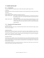
10. 3. Charger Wire Cleaner Operational Circuit
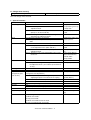
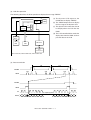
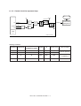
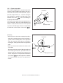
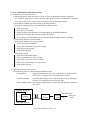
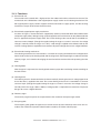
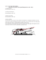
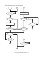
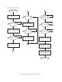
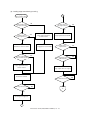
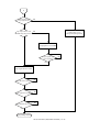
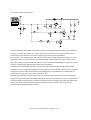
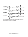
(1) Role of the charger wire cleaner circuit
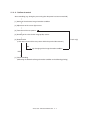
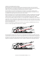
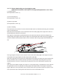
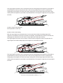
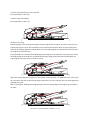
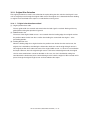
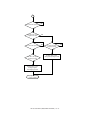
This circuit is for cleaning the main charger wire. It reciprocates the wire cleaner regularly to avoid
a poor charging and irregularities of the drum.
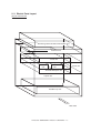
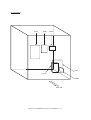
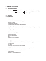
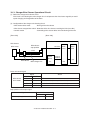
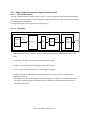
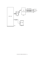
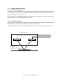
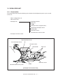
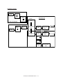
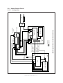
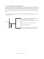
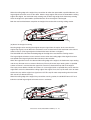
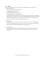
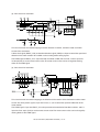
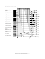
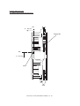
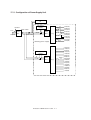
(2) Configuration of the charger wire cleaning circuit
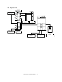
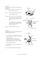
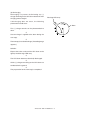
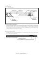
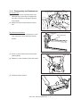
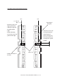
• Wire cleaner drive motor
: Driving of the wire cleaner
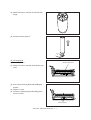
• Wire cleaner stop position switch : Detection of the wire cleaner reaching the limit (rear side)
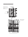
• Control section
: Controlling of the cleaner drive unit and cleaning of the wire
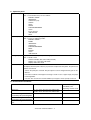
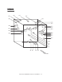
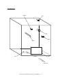
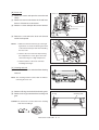
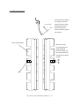
[Front side]
[Rear side]
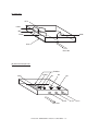
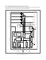
Control section
PWA-F-LGC-340/341/342
Wire cleaner
Wire cleaner
drive motor
MCLSW-0
stop position
Gate
Main
array
CPU
switch
Motor
CLMTA-0
CLMTB-0
driver
Wire cleaner
Main charger wire
IC58
IC56
IC9
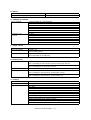
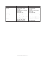
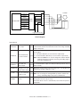
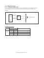
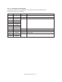
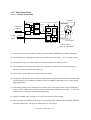
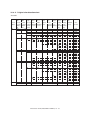
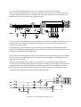
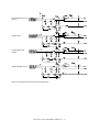
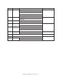
Drive unit control signal
Signal
Status
CLMTA-0
CLMTB-0
Wire cleaner
“L” level
“L” level
OFF
drive motor
“H” level
“L” level
Reverse rotation (Home position limit)
“L” level
“H” level
Forward rotation (Limit Home position)
“H” level
“H” level
Brake
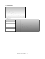
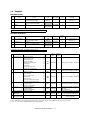
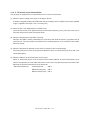
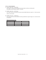
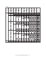
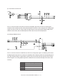
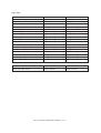
Stop position switch input signal
Signal
MCLSW-0 (Stop position switch)
Status
“H” level
“L” level
Not detected
Detected
AR-651/810 PROCESS SECTION 10 - 3

















































































































![取扱説明書[NI-FS350]](http://vs1.manualzilla.com/store/data/006555666_3-60968ee3a84023c894538f98d15ad355-150x150.png)