1
HP Vectra User’s Guide
Table of Contents
WELCOME TO YOUR HP VECTRA PC
1 SETTING UP YOUR PC
55
UNPACKING YOUR PC
CONNECTING THE DISPLAY, MOUSE, AND KEYBOARD
CONNECTING TO A NETWORK
CONNECTING A PRINTER
CONNECTING AUDIO ACCESSORIES
CONNECTING A SCSI ACCESSORY
CONNECTING THE POWER CORDS
STARTING AND STOPPING YOUR PC
INSTALLING AN OPERATING SYSTEM
INSTALLING THE WINDOWS NT WORKSTATION OPERATING
SYSTEM
INSTALLING THE OS/2® OPERATING SYSTEM
INSTALLING WINDOWS 95
2 USING YOUR PC
54
55
56
57
58
59
59
61
63
65
66
69
72
75
WORKING IN COMFORT
REPETITIVE STRAIN INJURY
QUESTIONS AND ANSWERS
INSTALLING YOUR DISPLAY
WHAT IS DISPLAYED ON THE SCREEN
USING A DOCUMENT HOLDER
YOUR HP KEYBOARD
YOUR DESK
YOUR CHAIR
YOUR POSTURE
YOUR WORKSPACE AND WORK ENVIRONMENT
LIGHTING
FURTHER SUGGESTIONS
SUMMARY RECOMMENDATIONS
BIBLIOGRAPHY OF ARTICLES FOR MORE INFORMATION
CONFIGURING PASSWORD SECURITY
SETTING A PASSWORD
USING YOUR CD-ROM DRIVE
LOADING A CD
EJECTING A CD WHEN THE OPEN/CLOSE BUTTON IS DISABLED
TIPS FOR USING YOUR PC
75
75
75
76
76
77
77
78
78
79
80
80
81
81
83
83
84
85
86
87
87
3 HOW TO INSTALL ACCESSORIES INSIDE YOUR PC
88
SUPPORTED HP ACCESSORIES
REMOVING AND REPLACING THE COVER
REPLACING THE COVER AFTER INSTALLING ACCESSORIES
MOVING THE POWER SUPPLY
REPLACING THE POWER SUPPLY AFTER INSTALLING
ACCESSORIES
INSTALLING MEMORY
MAIN MEMORY MODULES
INSTALLING MORE MEMORY ON THE MGA VIDEO ADAPTER
INSTALLING ACCESSORY BOARDS
CONFIGURING ACCESSORY BOARDS WITH PLUG AND PLAY
INSTALLING THE BOARD
INSTALLING DISK DRIVES
INSTALLING A HARD DISK DRIVE
COMPLETING THE INSTALLATION OF A HARD DISK DRIVE
INSTALLING A DRIVE IN A FRONT-ACCESS SHELF
INSTALLING A PROCESSOR
COMPLETING THE INSTALLATION OF A PROCESSOR
88
89
92
93
94
95
95
96
98
98
100
103
104
110
111
114
117
4 TROUBLESHOOTING YOUR PC AND USING THE SETUP
PROGRAM
118
SOLVING PROBLEMS
IF YOU CANNOT SOLVE THE PROBLEM
IF YOUR PC DOES NOT START
IF YOUR DISPLAY IS BLANK AND THERE ARE NO ERROR
MESSAGES
IF AN ERROR MESSAGE APPEARS
IF YOUR PC HAS A HARDWARE PROBLEM
IF YOUR DISPLAY DOES NOT WORK
IF YOUR KEYBOARD OR MOUSE DOES NOT WORK
IF YOUR PRINTER DOES NOT WORK
IF THE FLEXIBLE DISK DRIVE DOES NOT WORK
IF THE HARD DISK DOES NOT WORK
IF AN ACCESSORY BOARD DOES NOT WORK
IF YOUR PC HAS A SOFTWARE PROBLEM
IF YOU HAVE FORGOTTEN YOUR PASSWORD
IF YOU CAN’T START THE SETUP PROGRAM
IF THE DATE AND TIME ARE INCORRECT
IF YOUR PC HAS AN AUDIO PROBLEM
IF THE CD-ROM DRIVE HAS A PROBLEM
USING THE HP SETUP PROGRAM
STARTING THE SETUP PROGRAM
UNDERSTANDING THE SETUP PROGRAM
USING THE SCSISELECT UTILITY
IF THE SCSI HARD DISK STOPS WORKING
118
119
119
119
120
123
123
124
125
125
126
126
127
127
127
128
128
129
130
130
132
137
141
IF YOU LOSE THE KEY
5 TECHNICAL INFORMATION
141
142
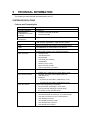
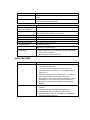
SYSTEM SPECIFICATIONS
AUDIO FEATURES
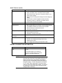
POWER CONSUMPTION INFORMATION
THE PC’S MEMORY MAP
IRQS, DMAS, AND I/O ADDRESSES USED BY YOUR PC
AVAILABLE VIDEO RESOLUTIONS
THE PC’S REAR CONNECTORS
SYSTEM CONNECTORS AND SWITCHES
SYSTEM BOARD CONNECTORS
VIDEO ADAPTER SWITCHES
SYSTEM BOARD SWITCHES
RECYCLING YOUR PC
142
143
144
145
146
147
148
149
149
150
151
152
6 HEWLETT PACKARD SUPPORT AND INFORMATION SERVICES
153
INTRODUCTION
153
YOUR HP AUTHORIZED RESELLER
153
HP SUPPORTPACK
154
HP SUPPORT ASSISTANT CD-ROM
154
HEWLETT-PACKARD INFORMATION SERVICES
154
HP FORUM ON COMPUSERVE
154
HP FORUM ON AMERICA ONLINE
155
HP BBS LIBRARY
155
INTERNET—FTP LIBRARY SERVICE
156
ACCESS HP WORLD WIDE WEB SITE
156
HP FAXBACK ON DEMAND—HP FIRST
156
HP AUDIO TIPS (USA ONLY) HP AUTOMATED SUPPORT DIRECTORY 156
ORDERING DRIVERS AND BIOS ON DISKETTE{XE "DRIVERS"}{XE
"BIOS"}
157
HP SUPPORT SERVICES
157
HEWLETT-PACKARD TELEPHONE SUPPORT
158
LIFELINE TELEPHONE SUPPORT
159
HP NETWORK PHONE-IN SUPPORT SERVICE (NPS)
159
SUMMARY
160
HEWLETT-PACKARD MARKETING HEADQUARTERS
161
HP WORLD WIDE WEB SERVER
161
HP ANONYMOUS FTP SERVER
161
EUROPEAN CUSTOMER SUPPORT CENTER
161
HP WORLD WIDE WEB SERVER
162
HP ANONYMOUS FTP SERVER
162
EUROPEAN CUSTOMER SUPPORT CENTER
162
GLOSSARY
163
7 REGULATORY INFORMATION AND WARRANTY 168
REGULATORY INFORMATION
FCC (FOR USA ONLY)
HP HARDWARE WARRANTY
HP SOFTWARE PRODUCT LICENSE AGREEMENT AND SOFTWARE &
PRODUCT LIMITED WARRANTY
168
168
170
172
WELCOME TO YOUR HP VECTRA PC
Congratulations on the purchase of your new Hewlett-Packard Personal Computer. Your highperformance HP Vectra PC provides:
•
a PentiumTM Pro processor in a Zero Insertion Force (ZIF) socket for easy processor
upgrades
•
processor-integrated level-two cache for improved performance
•
16 MB of ECC (error correcting code) memory, upgradeable to 256 MB
•
an Ultra VGA PCI (Peripheral Component Interconnect) video controller with 2 MB of
video memory (upgradeable to 4 MB)
•
an integrated Enhanced IDE (Integrated Drive Electronics) controller on the PCI bus
supporting Fast IDE and Standard IDE
•
an integrated Ultra SCSI controller on the PCI bus supporting Fast-20 SCSI-2 (up to 20
MB-per-second data transfer rate) and SCSI Plug and Play (SCAM) compliant devices
•
a 32-bit PCI 100VG/10BaseT Ethernet LAN controller
•
seven mass storage shelves:
• five front-access shelves
• two internal shelves
•
six slots for accessory boards:
• three 32-bit PCI (Peripheral Component Interconnect) slots
• two 16-bit ISA (Industry Standard Architecture) slots
• one combination ISA or PCI slot
•
a quad-speed CD-ROM drive on the SCSI bus
•
an integrated SoundBlasterTM 16 audio interface on the ISA bus
•
headphones jack, microphone jack, and volume control on the front panel
•
MIDI/joystick interface connector, audio Stereo In jack, and audio Stereo Out jack on the
rear panel
•
Wavetable upgrade connector on the system board
•
one SCSI connector, one parallel port, and two serial ports on the rear panel
•
System BIOS and Video BIOS stored in Flash ROMs (for easy upgradeability)
•
BIOS support for ISA “Plug and Play” accessory board configuration
•
Optimized for 32-bit operating systems.
NOTE
The advanced processor installed in your HP Vectra
PC provides the best performance when used with
32-bit operating systems and applications.
1
SETTING UP YOUR PC
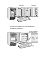
This chapter leads you through the first time installation of your HP Vectra PC.
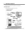
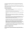
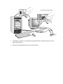
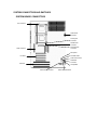
UNPACKING YOUR PC
1
When you receive your PC, unpack all of the components:
•
•
•
•
the computer and power cords
the display and its video cable
the keyboard and mouse
the manuals and disk kit.
This Manual
Video Cable
Power Cords
Display
Computer
Mouse
Disk kit
Keyboard
NOTE
2
Device drivers, HP utilities, and an online Network
Administrator Guide are provided in a disk kit.
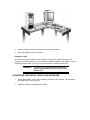
Place the PC on (or under) a sturdy desk with easily accessible power outlets, and enough
space for the keyboard, mouse, and any other accessories.
3
Position the PC so that its rear connectors are easily accessible.
4
Place the display next to the computer.
Installation Tools
No tools are required to install your PC. However, if you plan to install a disk drive or an
accessory board inside your PC, you will need a flat-blade screwdriver. See chapter 3, How to
Install Accessories Inside Your PC, for more information on installing accessories.
WARNING:
If you are in any doubt that you can lift the PC
and the display safely, do not try to move them
without help.
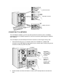
CONNECTING THE DISPLAY, MOUSE, AND KEYBOARD
1
Connect the display, mouse, and keyboard to the back of the computer. The connectors
are shaped to go in one way only.
2
Tighten the display cable attachment screws.
Mouse Connector
Keyboard Connector
Display Connector
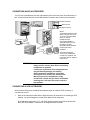
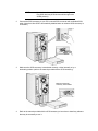
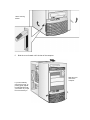
CONNECTING TO A NETWORK
The LAN Adapter installed in your PC may have two RJ-45 connectors (one for 100-Mbit/s
operation and one for 10-Mbit/s operation) or one RJ-45 connector (supporting both 100-Mbit/s
and 10-Mbit/s).
The LAN Adapter can automatically detect which connector or network type is being used.
1
Connect the RJ-45 plug on your network cable to the 100-Mbit/s or 10-Mbit/s LAN
connector on the LAN Adapter as appropriate for your network type. Push the plug into the
connector until the plug clicks into place.
100-Mbit/s
Connect the
network cable to
the 100-Mbit/s or
10-Mbit/s LAN
connector
(Your LAN
adapter may
have one
connector which
supports both
network types.)
10 Mbit/s
2
Attach the other end of the LAN cable to a hub (or into a wall jack that is connected to a
hub).
Let your Network Administrator know you are connecting your PC to the network. Refer to
the online Network Administrator Guide (provided with the disk kit) for instructions on
setting up your PC for a LAN connection.
CONNECTING A PRINTER
If you have a printer, connect its cable to the back of the computer and tighten the attachment
screws. Use these connectors:
•
•
•
Parallel (25-pin parallel connector) for a parallel device
Serial A (9-pin serial connector) for a serial device
Serial B (9-pin serial connector) for a second serial device.
Serial B
Serial A
Parallel
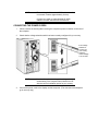
CONNECTING AUDIO ACCESSORIES
Your PC has a Headphones jack and a Microphone jack on the front panel. An audio Stereo In
jack, an audio Stereo Out jack, and a MIDI interface connector are located on the rear panel.
MIDI connector
Stereo in jack
Stereo out jack
NOTE
The internal speaker and the
Stereo Out jack on the rear
of your PC are deactivated
when you use the
Headphones jack.
The internal speaker is
deactivated when you use
the Stereo Out jack.
Note that external speakers
should have built-in
amplifiers.
The audio accessories
shown h ere (headphones,
microphone, speakers, and
hifi system) are not supplied
with your PC.
WARNING:
To avoid discomfort from unexpected noise,
always turn the volume down before connecting
headphones or speakers.
Listening to loud sounds for prolonged periods
may permanently damage your hearing.
Before putting on headphones, place them
around your neck and turn the volume down.
When you put on the headphones, slowly
increase the volume until you find a comfortable
listening level, and leave the volume control in
that position.
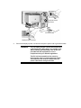
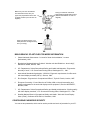
CONNECTING A SCSI ACCESSORY
Note that Ultra SCSI mode is disabled automatically when an external SCSI accessory is
connected to your PC.
1
Refer to the manual provided with the SCSI accessory for instructions on selecting a SCSI
address. You should assign an unused SCSI address to the accessory.
SCSI addresses range from 0 to 7, with SCSI address 0 used by the first SCSI hard disk
drive and SCSI address 7 reserved for the integrated SCSI controller.
NOTE:
You don’t need to set a SCSI address for Plug and
Play SCSI devices (SCSI devices which support the
SCAM protocol).
2
Connect the SCSI accessory to your PC’s external SCSI connector with a shielded SCSI
cable. (Note that Ultra SCSI is automatically disabled when an external SCSI accessory is
connected.)
3
Make sure the SCSI accessory is terminated correctly—either internally or by a
terminating resistor (refer to the manual provided with the SCSI accessory).
Make sure the SCSI
accessory is terminated
4
Refer to the manual provided with the SCSI accessory to learn how to install any software
that may be necessary to use it.
NOTE
The total length of the external SCSI cables should
not exceed 3 meters (approximately 10 feet).
Contact your dealer to order shielded HP SCSI
cables to connect external SCSI accessories.
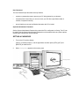
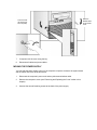
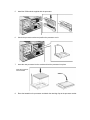
CONNECTING THE POWER CORDS
1
If fitted, remove the warning label covering the computer’s power connector on the rear of
the computer.
2
Check that the voltage selection switch has been correctly configured for your country.
If the voltage
selection is
incorrect for
your country,
select the
correct voltage
115V or 230V
NOTE
3
You should not have to change the voltage selection
switch setting if the computer was ordered from HP
with the correct localization option for your country.
Connect the power cords to the display and the computer. (The connectors are shaped to
go in one way only.)
Computer Power
Connector
Grounded Outlet
Display Power Connector
4
Connect the display’s power cord and the computer’s power cord to grounded outlets.
WARNING:
For your safety, always connect the equipment to
a grounded wall outlet. Always use a power cord
with a properly grounded plug, such as the one
provided with this equipment, or one in
compliance with your national regulations.
This PC is disconnected from the power by
removing the power cord from the power outlet.
This means the PC must be located close to a
power outlet that is easily accessible.
STARTING AND STOPPING YOUR PC
Starting Your PC
1
Press the power button on the display.
Switch on the display
Then switch on the PC
2
Press the power button on the PC.
The PC performs a power-on self-test. If an error is detected, a message is displayed.
Follow the instructions provided to correct the error.
NOTE
If the space bar on your keyboard has a power-on
icon, you can start the PC by pressing the space bar.
(This feature can be enabled or disabled with the
Setup program — see chapter 4 for more information
about the Setup program.)
Note that you cannot stop your PC by pressing the
space bar.
3
If a Password has been set in the PC’s Setup program, the power-on prompt appears
when you switch on the PC. If the power-on prompt is displayed, type your Password and
press [ENTER] to use the PC.
Correct password
Wrong password
Restart the PC, then
enter your password
again
4
When your PC has started:
•
Adjust the display screen’s brightness and contrast to your needs. If the picture does
not fill the screen or is not centered refer to the display’s manual for instructions.
•
Set the keyboard to a comfortable position.
Adjust brightness
(your display may be different
from the display shown here)
Stopping Your PC
1
To stop your PC, make sure that you have exited all programs then shutdown your
operating system (refer to your operating system reference guide for details if you are not
sure how to shutdown your operating system).
2
Press the power button to stop your PC.
NOTE
If Windows 95 is installed, select Shutdown from the
Start menu and the PC will power off. It is not
necessary to press the power button.
Resetting Your PC
The Reset button lets you restart the PC without switching the PC off and then on again. Make
sure that you have exited all programs then shutdown your operating system before you press
the reset button.
You may need to push
hard on the reset button
INSTALLING AN OPERATING SYSTEM
This section provides information on installing the Windows NT Workstation operating system,
OS/2 Warp Connect, and Windows 95 on your HP Vectra. For detailed installation information,
refer to the manual that came with your operating system.
INSTALLING THE WINDOWS NT WORKSTATION OPERATING SYSTEM
The following instructions describe a simple installation of the US English version of the
Windows NT Workstation operating system on a Vectra PC with a SCSI hard disk. For
complete installation information, consult the manual that came with the operating system.
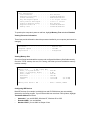
Preparing to Install Windows NT
Your PC is supplied with a disk kit, comprising one “XU/VT Boot” diskette and one “XU/VT
Drivers and Documentation” CD-ROM disk. You will need to copy some important files (system
drivers) from the CD-ROM to a blank diskette, before attempting to install Windows NT.
To copy the files from the CD-ROM:
1
Use the MS-DOS DISKCOPY command to make a duplicate copy of the “XU/VT Boot”
diskette onto the blank diskette, then store the original “XU/VT Boot” diskette in a safe
place.
2
Label the duplicate diskette: “XU/VT Boot” diskette.
3
Insert the duplicate “XU/VT Boot” diskette in the flexible disk drive and insert the “XU/VT
Drivers and Documentation” CD-ROM disk in the CD-ROM drive.
4
Restart your PC and press [F2] to enter the Setup program.
5
Highlight Operating System and select Windows NT. Press the [F3] key to save the
setting and exit the Setup program.
6
When your PC restarts, it will start (boot) from the inserted diskette. Follow the displayed
instructions to copy the files needed for an installation of Windows NT.
7
Remove the disks from your computer when the files have been copied from the CD-ROM
disk to the duplicate diskette.
Installation Procedure
Before installing Windows NT, make sure you have these disks:
•
•
•
Windows NT Setup disks
(Setup Boot disk, Setup disk #2, and Setup disk #3)
Windows NT CD-ROM
the duplicate “XU/VT Boot” diskette.
1
Insert the Windows NT “Setup Boot Disk” into drive A and insert the Windows NT CDROM in the CD-ROM drive. Restart your PC.
2
Insert “Setup Disk #2” when prompted by the installation program.
3
Press [ENTER] to setup Windows NT.
4
Press [ENTER] to select the Express Setup.
NOTE
If you are installing the US English version of
Windows NT with a localized (non-US English)
keyboard, you should choose the Custom Setup. The
Custom Setup gives the option of selecting a
localized keyboard.
5
Insert “Setup Disk #3” when prompted by the installation program.
6
When the installation program reports that no mass storage devices have been found,
press S to specify an additional device.
7
Select Other by pressing [ENTER]. Remove “Setup Disk #3”, insert the duplicate “XU/VT
Boot” diskette, and then press [ENTER].
8
Press [ENTER] to select the displayed Adaptec driver and then press [ENTER] to continue
the installation.
9
Insert “Setup Disk #3” when prompted by the installation program.
10
Press [ENTER] to install Windows NT from the CD-ROM.
11
Follow the instructions displayed by the installation program. When asked to insert the
Adaptec driver diskette, insert the duplicate “XU/VT Boot” diskette and press [ENTER] to
retry.
12
When the files have been copied from the duplicate “XU/VT Boot” diskette, remove the
diskette and press [ENTER] to restart your computer.
13
Follow the instructions displayed by the Windows NT installation program to continue the
installation of Windows NT.
14
When the installation program tries to detect the network adapter, click Continue, then
select Continue in the next dialog box.
15
Select No Network in the Add Network Adapter dialog box, then click OK to confirm
your choice. (The installation of network drivers is explained in the following section.)
16
Continue the Windows NT installation until a dialog box proposes the type of display
connected to your computer.
17
Click OK to select the VGA Compatible Display, then click OK to save the configuration.
18
When the installation of Windows NT is complete, click Restart Computer to restart your
computer.
Enabling Networking After Installation
To enable networking, start Windows NT and follow these steps:
1
In the Control Panel, choose the Network icon.
2
Click Yes when the Install Network Now message appears.
3
Confirm (or change) the proposed setup path, which is the source of the Windows NT
installation files on the Windows NT CD-ROM (for example, D:\i386).
4
Click Continue to install the HP network driver for Windows NT. To install the driver:
a
Choose Do Not Detect to manually select an adapter.
b
Click Continue to choose a network adapter.
c
In the list box, choose Other and then select Continue.
d
Insert the duplicate “XU/VT Boot” diskette and specify the location of the drivers with
A:\LAN.
e
Choose the displayed HP 10/100VG network adapter.
5
The system will continue with the installation. Follow the instructions displayed by
Windows NT to complete the network driver installation process.
6
When prompted by the installation program, click on Restart Computer.
Changing the Video Driver after Installation
Windows NT starts in VGA mode by default. To install the latest HP qualified video driver for
Windows NT:
1
In the Control Panel, choose the Display icon.
2
Choose Change Display Type.
3
Click Change.
4
To install the HP video driver:
a
Choose Other.
b
Insert the duplicate “XU/VT Boot” diskette and specify the location of the drivers with
A:\VIDEO.
c
Choose your desired resolution from the list of Matrox MGA Millennium drivers and
click Install.
d
When asked to confirm the location of the drivers, verify that A:\VIDEO is displayed
then click Continue.
e
When the files have been copied from the duplicate “XU/VT Boot” diskette, follow the
displayed instructions to restart the computer.
Enabling the integrated Audio Interface after Installation
To enable the integrated audio interface:
1
In the Control Panel, choose the Drivers icon.
2
Click on Add.
3
Remove the highlighted adapter.
4
Click Add.
5
Choose Creative Labs Sound Blaster 1.x, Pro, 16 from the list and click OK.
6
Confirm the proposed settings in the following dialog box, then click OK.
NOTE
The proposed settings will correspond, by default,
with the Audio Interface settings in the HP Setup
program. If an error message appears, check that the
proposed settings are the same as those configured
in the Setup program. Refer to chapter 4 for more
information about the Setup program.
Changing the SCSI Driver after Installation
To install the latest HP qualified SCSI driver for Windows NT:
1
Click the Windows NT Setup icon.
2
In the Options menu, choose Add/Remove SCSI Adapters.
3
Click on Remove, to remove the highlighted adapter.
4
Click Add, to add a new adapter.
5
Choose Other from the list box.
6
Insert the duplicate “XU/VT Boot” diskette (or a diskette containing the latest qualified
SCSI driver) and specify the location of the driver, for example A:\SCSI.
7
When the name of the new Adaptec SCSI driver is displayed, click OK to select it.
8
Choose Install, then click New.
9
After the installation, follow the instructions displayed by Windows NT to restart the
computer.
INSTALLING THE OS/2® OPERATING SYSTEM
These instructions explain how to install OS/2 Warp Connect on a HP Vectra PC with a SCSI
hard disk. For complete installation information, consult the manual that came with the
operating system diskettes.
Before installing OS/2 Warp, make sure you have these disks:
•
•
OS/2 Warp installation disks
“XU/VT Drivers and Documentation” CD-ROM.
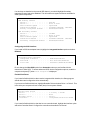
Preparing to Install OS/2 Warp
1
Start your PC and press [F2] to enter the Setup program.
2
Highlight Operating System and select IBM OS/2. Press the [F3] key to save the setting
and exit the Setup program.
Installation Procedure
Consult the manual that came with your OS/2 Warp installation disks for a detailed explanation
of the installation procedure.
When the installation program prompts you to install networking support, select No. Networking
support should be installed after completing the installation of OS/2 Warp.
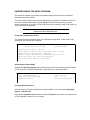
When the installation of OS/2 Warp has completed, two error messages will appear when your
computer is restarted:
SYS1201: The device driver C:\MMOS2\SB16D2.SYS... was not
installed
SYS1201: The device driver C:\MMOS2\AUDIOVDD.SYS... was not
installed
Press [ENTER] to continue when each error message appears. (These messages will appear
because the HP SCSI drivers have not yet been installed. You must install the HP SCSI
drivers, as described below, to prevent this error message appearing again.)
Installing the HP SCSI Drivers
To install the latest HP qualified SCSI driver for OS/2:
1
Insert the “XU/VT Drivers and Documentation” CD-ROM into the CD-ROM drive.
2
Open the OS/2 System folder, then the System Setup folder.
3
Click on the Device Driver Install icon.
4
Change the source directory for the drivers with the Change button to D:\SCSI\OS2.
5
Click the Install button. The drivers will be copied from the CD-ROM.
6
Exit from the OS/2 Device Driver installation.
7
Shutdown OS/2, then restart your computer to use the new SCSI drivers.
Installing the HP Network Drivers
To install networking support with the latest HP qualified network drivers for OS/2:
1
Insert the “XU/VT Drivers and Documentation” CD-ROM into the CD-ROM drive.
2
Open the OS/2 System folder, then open the OS/2 Warp Connect Install/Remove folder.
3
Click on Warp Connect Selective Install for Networking.
4
Select an installation on this workstation (local install).
5
Follow the instructions displayed by the installation program.
6
Click on the Other Adapter button, when the Select Network Adapter dialog box
appears.
7
Enter D:\LAN\IBM\OS2, when asked for the file location, and click OK.
8
The HP PCI Integrated 10/100VG Interface will be displayed in the Drivers Found dialog
box. Select Ethernet as the Type of LAN.
9
When the Select Network Adapter dialog box appears, the HP PCI Integrated 10/100VG
Interface is highlighted in the adapter list.
10
Remove the “XU/VT Drivers and Documentation” CD-ROM from the CD-ROM drive, insert
the OS/2 Warp Connect CD-ROM and then click OK.
11
Click OK in the Select Network Adapter dialog box, to accept the selection of the
adapter.
12
Click OK, then click OK again in the configuration dialog box.
13
Click the Install button in the Ready to Install window.
14
Select OK to confirm the shutdown of the operating system. Leave the OS/2 Warp
Connect CD-ROM in the drive (some files will be copied from the CD-ROM when the
operating system restarts).
Installing the HP Video Driver
After successful installation of OS/2, you should install the HP video driver from the “XU/VT
Drivers and Documentation” CD-ROM.
1
Insert the “XU/VT Drivers and Documentation” CD-ROM in the CD-ROM drive.
2
In the OS/2 System folder, open the Command Prompts folder and click on the OS/2
Full Screen icon.
3
At the command prompt, type the following:
D: [ENTER]
CD VIDEO\DISK5 [ENTER]
INSTALL /U [ENTER]
This will start an ‘unattended’ installation of the video drivers.
4
When the installation of the drivers has completed, exit from the command prompt,
shutdown the operating system, then restart the system.
Selecting a Display
1
In the OS/2 System folder, open the Command Prompts folder and click on the OS/2 Full
Screen icon.
2
At the command prompt, type the following:
CD \MGA\OS2 [ENTER]
MGAMON [ENTER]
This will start the MGA Display selection program. Choose your display (monitor) from the
list.
3
When this selection process has completed, exit from the command prompt, shutdown the
operating system, then restart the system.
Changing Display Settings
1
In the OS/2 System folder, open the System Setup folder.
2
Click on the System icon and change the settings (for example, the screen resolution).
INSTALLING WINDOWS 95
These instructions explain how to install the US English version of Windows 95 (for PCs
without Windows) on a HP Vectra PC with a SCSI hard disk. For complete Windows 95
installation information, consult the manual that came with your Windows 95 diskettes.
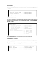
Preparing to Install Windows 95
Your PC is supplied with a disk kit, comprising one “XU/VT Boot” diskette and one “XU/VT
Drivers and Documentation” CD-ROM disk. Before attempting to install Windows 95 you should
make a duplicate copy of the “XU/VT Boot” diskette onto a blank diskette:
1
Use the MS-DOS DISKCOPY command to make a duplicate copy of the “XU/VT Boot”
diskette onto a blank diskette, then store the original “XU/VT Boot” diskette in a safe place.
2
Label the duplicate diskette: “XU/VT Boot” diskette.
3
Restart your PC and press [F2] to enter the Setup program.
4
Highlight Operating System and select Windows 95. Press the [F3] key to save the
setting and exit the Setup program.
Installation Procedure
Install Windows 95 from the Windows 95 (for PCs without Windows) installation disks, following
the instructions in the manual supplied with the Windows 95 diskettes.
1
When Windows 95 is installed, shutdown the PC by selecting Shutdown from the Start
menu.
2
Switch off the PC.
3
Insert the duplicate “XU/VT Boot” diskette in the flexible disk drive and insert the “XU/VT
Drivers and Documentation” CD-ROM in the CD-ROM drive.
4
Switch on the PC.
5
Select the Windows 95 Diskette Kit option from the menu. This option copies the SCSI
drivers from the “XU/VT Drivers and Documentation” CD-ROM to the hard disk.
6
When the files have been copied, remove the diskette and the CD-ROM, then restart your
PC.
7
To install the SCSI drivers after restarting your PC, click on the Start button then:
point to Settings,
click on Control Panel,
double-click on System,
and click on the Device Manager tab.
8
Double-click on Other Device then double-click on PCI SCSI Bus Controller.
9
Click on the Driver tab and then click on the Change Driver button.
10
Click on Other Devices, then click on OK. Confirm the selection of the Adaptec AIC-7880
PCI SCSI Controller by clicking on OK.
11
Click on OK then click on OK again. Click on Cancel when the Test button appears.
12
Windows 95 will build a new driver database and install the new SCSI drivers. Restart the
PC to activate the SCSI drivers.
Installing the MGA Video Driver
1
Insert the “XU/VT Drivers and Documentation CD-ROM” in the CD-ROM drive.
2
Double-click on the My Computer icon on the Windows 95 desktop.
3
Double-click on the CD-ROM drive icon, then on the Video folder, then on the folder
named Disk 6.
4
Execute the file named Setup (to start the MGA Millennium PowerDesk Setup).
5
Click on the Next button to accept the default destination path.
6
Click on the Next button to confirm the installation of Quick Access and the MGA
Monitor Program.
7
Click OK in the Information . . . window.
8
Click OK in the next dialog box, when asked to use the Windows 95 monitor mechanism.
9
Click OK when a message explains that the driver has been installed.
10
Click on the Start button of the MGA Change Display Wizard.
11
Click on the Settings tab in the Display Properties folder.
12
Click on Change Display Type.
13
Click on Change of the Adapter Type (the adapter will be incorrectly detected as “Oak
Technology Super VGA”).
14
Click on Have Disk.
15
Enter D:\VIDEO\DISK6 as the path to copy the files from.
16
Click on OK to confirm MGA Millennium Power Desk. (The files will be copied from the
CD-ROM to the hard disk.)
17
Click Close in the Change Display Type folder.
18
Click Finish on the MGA Change Display Wizard.
19
Click Yes to restart in the MGA Exit Wizard dialog box. Windows 95 will restart with the
new video drivers.
Configuring the Display
1
Click on the Start button then:
point to Programs,
click on MGA Millennium Power Desk,
and double-click on MGA Monitor Program.
2
Click on the Selection button, select your display, then confirm your selection with OK.
3
Click on Save and Exit, then select Restart to restart Windows 95.
Changing Display Settings
1
Click on the Start button then:
point to Settings,
click on Control Panel,
and double-click on Display.
2
Click on the MGA Settings tab to change display settings.
Configuring the Network
1
Click on the Start button then:
point to Settings,
click on Control Panel,
and double-click on the Network icon.
2
Click on the Add button and, in the Select Network Component Type window, choose
Adapter then click on the Add button.
3
Click on the Have Disk button, then insert the “XU/VT Drivers and Documentation” CDROM in the CD-ROM drive.
4
In the Install from Disk window, specify the path for the files on the CD-ROM with
D:\LAN\W95.
5
Click OK to confirm the selection of the HP PCI Integrated 10/100VG Interface.
6
Restart the PC, by selecting Shutdown from the Start menu.
2
USING YOUR PC
This chapter gives important ergonomic advice, explains how to set a password, and shows
how to use your CD-ROM drive.
WORKING IN COMFORT
Thank you for choosing Hewlett-Packard equipment. To maximize your comfort and
productivity it is important that you set up and use your equipment properly. This section of the
User’s Guide provides guidance and hints, based on the latest ergonomic findings, to help you
work in a comfortable and ergonomically low-risk environment. Also, international regulations
and guidelines are included from the European Community Display Screen Equipment
directive and ISO 9241 to ensure that the information presented is applicable worldwide.
Please be aware that the quoted dimensions are for an average person. They may need to be
adjusted to your individual physical characteristics. For example: if you are an extra tall person,
your work surface may need to be higher than the range listed. Prior to using any HewlettPackard equipment, study these instructions and suggestions and consult the bibliography at
the end of this section. If, during use of this or any other equipment, you experience pain or
discomfort, stop work and review this section of the User’s Guide. Should the discomfort return,
discontinue use of the equipment and consult a doctor as soon as possible.
REPETITIVE STRAIN INJURY
Because your safety and comfort is our primary concern, we strongly recommend that our
equipment be used in accordance with ergonomic standards and recommendations. Recent
literature suggests that there may be a relationship between injury to soft tissues, especially in
the hands and arms, and the prolonged use of keyboards or other equipment requiring
repeated motions of the hands and forearms. Literature also suggests that there are many
other risk factors which may increase the chance of such soft-tissue injury, commonly called
Repetitive Strain Injury.
QUESTIONS AND ANSWERS
What is RSI?
Repetitive Strain Injury (RSI - also known as cumulative trauma disorder or repetitive motion
injury) is a type of injury where soft tissue in the body, such as muscles, nerves, or tendons,
become irritated or inflamed. In an extreme case, this irritation can lead to permanent tissue
damage. RSI has been a reported problem for workers performing specific tasks such as
assembly line work, meat packing, sewing, playing musical instruments, and VDT work. It may
also result from other activities such as carpentry, knitting, housework, gardening, tennis, wind
surfing, and lifting children.
Why is it important for me to exercise care in how I set up and use my equipment?
Some people who use VDTs experience physical discomfort during their use. Sometimes this
discomfort leads to a repetitive strain injury. Setting up and using equipment properly can help
to minimize this discomfort. Use your equipment in an appropriate way. Well-designed and
adjusted equipment may not be sufficient to eliminate all potential problems. How you perform
your VDT activities is also important.
What causes RSI?
RSI is caused by any demanding activity that exceeds the ability of the body to do work.
Common factors that are associated with RSI include too many uninterrupted repetitions of an
activity or motion, performing an activity in an awkward or unnatural posture, maintaining static
posture for prolonged periods, failing to take frequent short breaks, and stress. Also, certain
medical conditions such as rheumatoid arthritis and diabetes may contribute to RSI.
What should I do if I start to experience RSI symptoms or discomfort?
By following the guidance on proper equipment and work environment set up and use, the risk
of developing RSI can be minimized. However, if you are experiencing any discomfort, seek
professional medical advice immediately. Typically, the earlier a problem is diagnosed and
treated, the easier it may be to resolve.
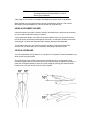
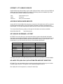
INSTALLING YOUR DISPLAY
Most HP displays come with a tilt and swivel feature that makes it easy to adjust the screen
position. If your display does not have this feature, consider acquiring an accessory to provide
this capability. The optimum distance between the eyes and the screen depends on the size of
the displayed characters.
•
Optimum readability is generally considered to be 21 minutes of arc. This corresponds to a
character size of 3.7 mm (0.15 in) at a viewing distance of 60 cm (24 in).
•
If your eyes are closer to the screen than 50 cm (20 in) undue stress may occur: Most
people prefer a viewing distance of approximately 60 cm (24 in).
•
The maximum viewing distance is usually limited by the character size and the available
space on the desk top.
The top of your display screen should be at or slightly below eye level. This will keep you from
looking down more than 15 to 20 degrees to see the center of the screen. You should not have
to look down more than 60 degrees for normal work tasks, such as typing or reading.
Ideally the screen should be positioned perpendicular to your line of sight. In case of
undesirable reflections, tilting the screen forward slightly usually solves the problem. However,
if this is not sufficient, it may be necessary to change the position of the display on the desk, or
change the location of the desk.
If this still does not correct the problem, try a good quality anti-glare filter, or a screen hood.
Keep the contrast and brightness adjusted to the level that is most comfortable for you. High
contrast and low brightness is usually the preferable combination. Since buildup of screen dirt
is gradual and therefore often overlooked, don't forget to clean the screen on a regular basis.
WHAT IS DISPLAYED ON THE SCREEN
Text should be easy to read. To help ease eye strain, try to adjust text attributes to make
reading the display as easy as possible (adjust such attributes as character size, spacing, and
color).
NOTE
The ISO 9241 and ANSI/HFS 100-1988 standards
give ample technical recommendations on how to
achieve good readability.
If the image on your screen is not stable, the display may require repair or adjustment.
When possible, use a program that has a simple "machine/user interface". Also, screen
information should be displayed in a structured and well organized way.
USING A DOCUMENT HOLDER
A document holder may make it easier to transfer information from a document to the screen
(or if you need to read while using your system).
If using a document holder, it should be at the same distance from your eyes as the screen,
next to the screen, and at the same height as the screen. An alternative location preferred by
some people is to locate the document holder between the screen and keyboard.
To help reduce stress on your neck and prevent eye fatigue, keep the back and forth
movement of your head and eyes to a minimum while using a document holder.
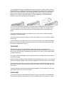
YOUR HP KEYBOARD
Your HP keyboard has a long cable so you can place it in the position most comfortable for you
while you are using the system.
The keyboard has a low profile to prevent excessive bending of your wrists while typing.
Literature suggests that you should not bend your wrists more than 10 degrees up or down, or
more than 10 degrees sideways. Keep your wrists straight by moving your entire hand and
forearm over to use the function keys or numeric keypad.
Your HP keyboard may have a kickstand which can be opened or closed to raise or lower the
keyboard angle. If your elbows are at about the same level as the work surface, then you may
choose not to use the kickstand. If your elbows are below the work surface, you may wish to
raise the back of the keyboard by using the kickstand. The point is to make sure that your
hands are in a "neutral" or flat position when you use the keyboard. This means that your
forearms, wrists, and hands should be in straight line.
You may use a wrist rest to help keep your wrists in a more comfortable and neutral position. If
you use a wrist rest, ensure that it is flush in height with the front edge of the keyboard, and
rounded or padded. Try not to rest your wrists on a sharp edge, such as a desk edge, when
typing.
It is recommended that you place your keyboard in front of the screen or document holder
(whichever is viewed the most).
If you use a mouse or trackball, position it close to the keyboard so you do not have to stretch
while using it.
It is not necessary to type with very much force. Use of too much force can place unnecessary
stress on your body, including tendons and muscles in your hands, wrists, and forearms, and
increase risk of discomfort or injury.
YOUR DESK
Sufficient desk space should be available to allow you to set up your equipment in a
convenient, comfortable arrangement. Recommended workstation desk space is 160 by 80 by
90 cm (63 by 32 to 36 inches). Depending on the nature of your work, you may need a smaller
or larger work surface.
To minimize reflections and glare (and thus eye discomfort), the surface of the desk should be
non-reflective (matt).
Ideally, the work top height should be adjustable. Recommended range is 66 to 77 cm (26 to 30
inches). If the desk top height is fixed, it should be between 72 and 75 cm (28.5 to 29.5 inches).
There should be at least 6 cm (2 inches) of space between your thighs and the desk top. If the
desk has a "kneehole" it should be at least 58 cm (23 in) wide, 65 cm (25.5 in) high, and 60 cm
(24 in) deep.
If possible, choose a desk with cable management capabilities. This will keep your cables and
wires orderly, off the floor, and out of the way.
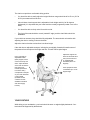
YOUR CHAIR
Your chair should have a stable base (for example: five legs with casters). It is important that
the casters be matched to the type of floor in your workspace (that is, hard surface or carpet).
The chair must provide a comfortable sitting position.
•
You should be able to easily adjust the height. Minimum range should be 40 to 52 cm (15.5 to
20.5 in) as measured from the floor.
•
It should have a back support that is adjustable in both height and tilt (0 to 30 degrees
backwards). It is important that your lower back be correctly supported (lumbar curve of the
back).
•
You should be able to freely swivel from side to side.
•
The front of the seat should be curved (“waterfall” edge), and the chair fabric should be
breathable.
If your chair has armrests, they should be fully adjustable. The arms should not interfere with
adjusting the chair or moving it close to the desk.
Adjust the chair so that the work surface is at elbow height.
If the chair has an adjustable seat pan, inclining the seat slightly forward will transfer some of
the pressure from the spine to the thighs and feet. This will relieve spine fatigue.
Use a chair with an
adjustable lumbar
(back) support, which
can be moved up and
down. Adjust the back
of the chair so that the
part that curves
outward (toward the
front of the chair)
corresponds to the part
of your lower back that
curves inward.
(Portable lumbar
cushions are also
available at medical
and office supply
houses.)
Adjust the angle of the
back rest and seat tilt so
that your back is erect
or angled slightly
backward (90 to 110
degrees)
Some people feel more
comfortable up to a 135
degree angle.
YOUR POSTURE
While sitting at your workstation, your back should be erect or angled slightly backwards. Your
back should be supported by the backrest.
Your arms should be relaxed and loose, elbows close to your sides, with the forearms and
hands approximately parallel with the floor.
Your wrists should be as straight as possible while using the keyboard, mouse, or trackball.
They should not have to be bent upward, downward, or to either side more than 10 degrees.
Your thighs should be horizontal or bent slightly downward. Your lower legs should be near a
right angle to your thighs. Your feet should rest comfortably on the floor (flat). If necessary, use
a footrest to get into a comfortable position.
Your head should be upright or tilted slightly forward (but not more than 15 degrees).
Avoid working with your head or trunk twisted in an unnatural position.
Change your position frequently to avoid fatigue.
YOUR WORKSPACE AND WORK ENVIRONMENT
To prevent muscle stiffness, you must have enough space to move around and vary your
position. Do not remain in one position for extended periods of time.
For better eye relief, the ceiling, walls, and floors should have a medium level of reflectance
(approximately 75%, 40%, and 30% respectively). Try to avoid excessive contrast between the
screen and its surroundings.
The work environment should be as quiet and free of distraction as possible (background noise
preferably below 55 dBA).
Where possible, relative air humidity should be in the range of 40 to 60%.
The recommendation for room temperature is 19 to 23 degrees C (66 to 73 degrees F). If
possible, adjust the temperature for whatever is comfortable to you.
The workplace should be well ventilated (as with any indoor environment).
LIGHTING
Lighting in your area should allow easy reading of documents and keyboard legends.
Recommended levels are:
•
Not too bright. Values over 1000 lux (100 foot candles) are considered to be too bright.
•
Recommended value is between 300 and 500 lux (30 to 50 foot candles).
•
For work on the screen, 300 lux (30 foot candles) is enough for most work.
•
When documents are to be read, 500 lux (50 foot candles) is recommended.
If more light is needed for a particular task, use an individual lamp ("task lighting") rather than
increasing the general lighting.
Incoming light should be shielded or diffused to prevent glare and distracting reflection. In
cases where strong sunlight is a problem, curtains, adjustable shades, or display hoods are
recommended.
If possible, try not to position the display in front of windows where glare, high contrast, and
reflections will interfere with your screen presentations. Try to position the display so the screen
is at a right angle to the window.
FURTHER SUGGESTIONS
•
Have your eyes checked on a regular basis and ensure your eyeglass prescription is
suitable for working on a display screen.
•
Look away from the screen from time to time to help reduce eye strain. Focus on distant
objects briefly. Also, blinking periodically helps lubricate the eyes.
•
Avoid holding your muscles tensed for long periods of time. Keep your fingers and body
relaxed.
•
Changing tasks frequently will help prevent muscle stiffness. For example: alternating
between using the keyboard, writing, filing, and moving around in your work environment,
helps keep muscles loose.
•
When prolonged screen work is required, take frequent short breaks. As a rule of thumb, a
five or ten minute break every hour is a good idea. Short frequent breaks are more
beneficial than longer less frequent breaks. Data shows that people who work for long
lengths of time without a break are more prone to injury.
•
Occasionally stretch the muscles in your hands, arms, shoulders, neck and back. You
should stretch at least as often as you take your breaks, that is, at least once per hour.
•
Discomfort, if any, may be alleviated by use of alternative ergonomic designs and
accessories such as: ergonomic personalized chairs, wrist rests, keyboard trays,
alternative input devices, non-prescription eye glasses, glare screens, and more. Seek
additional information from the sources available to you, including your employer, doctor,
local office supply store, and the bibliography provided at the end of this section.
•
If you experience any discomfort, discontinue use and see a doctor as soon as possible. If
you want additional information on VDT setup, ergonomics and related topics, consult your
employer and the sources listed at the end of this section.
SUMMARY RECOMMENDATIONS
The recommendations in the following illustrations are drawn from the latest available
international ergonomic standards and recommendations, including ISO 9241 and ANSI/HFS
100-1988.
Do not tilt your head forward by
more than 15 degrees, and try not to
turn your head toward the side.
Make sure frequently
used equipment is within
easy reaching distance
from your body. For
example, if you are
primarily using the
keyboard, place it directly
in front of you, not to the
side. If you are primarily
using the mouse, place it
in front of your hand or
arm.
If you are using both a
mouse and a keyboard,
place them both at the
same work surface
height.
Adjust your seat height, work surface
or both to position the surface at
approximately elbow height.
Place your display so that the top of
the screen is at or slightly below eye
level (but no more than 15 degrees).
If a wrist rest
is used, the
height should
be flush with
the front edge
of the
keyboard.
Make sure there
is sufficient
room under the
work surface for
your legs.
If after adjusting your chair you
cannot rest your feet comfortably
on the ground, use a footrest,
preferably adjustable in height
and angle.
Remember to occasionally shift position and move your body. Keeping your body "locked"
in one position for a long period of time is unnatural and stressful.
Make sure your arms and elbows
are relaxed and loose, with your
upper arm perpendicular to the floor
or slightly forward (no more than 30
degrees)
Keep your forearms and hands
approximately parallel with the floor
(elbows bent between 70 and 115
degrees)
Keep your elbows close to your
sides (less than 20 degrees away
from your body)
BIBLIOGRAPHY OF ARTICLES FOR MORE INFORMATION
1
Caisse Nationale d’Assurances: “Le travail a l’écran de visualisation”, Lucerne
(Switzerland), 1991.
2
Bayerisches Staatsministerium für Arbeit: “Arbeiten mit dem Bildschirm - aber richtig!”,
Max Schick GmbH, Munich, 1992.
3
U.S. Department of Labor/Occupational Safety and Health Administration: “Ergonomics:
the study of work”, U.S. Government Printing Office, Washington D.C., 1991.
4
International Standards Organization: “ISO 9241: Ergonomic requirements for office work
with visual display terminals (VDTs)”, Geneva, 1992.
5
Eric Granjean: “Ergonomics in Computerized Offices”, Taylor & Francis, London, 1987.
6
European Community: “Council directive of 29 May 1990 on the minimum safety and
health requirements for the work with display screen equipment”, Directive 90/270/EEC,
Brussels, 1990.
7
U.S. Department of Labor/Occupational Safety and Health Administration: “Working safely
with video display terminals”, U.S. Government Printing Office, Washington D.C., 1991.
8
Swedish National Board of Occupational Safety and Health: “Work with Visual Display
Units (VDUs)”, Ordinance AFS 1992:14, Stockholm, 1992.
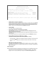
CONFIGURING PASSWORD SECURITY
You can set two passwords, which can be used to provide two levels of protection for your PC.
User Password
The User Password provides these security features:
•
a power-on password prompt to prevent your PC being started in your absence
•
a keyboard lock timer which you can use to lock your PC after a specified number of
minutes of keyboard inactivity
•
screen blanking to conceal confidential data when the PC is locked.
System Administrator Password
Set the System Administrator Password to protect the PC’s configuration in Setup. The PC can
be started, but the System Administrator Password must be entered before any Setup options
(except User Preferences) can be modified.
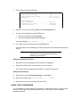
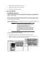
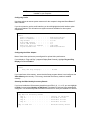
SETTING A PASSWORD
1
Turn on the PC and the display.
If the PC is already turned on, exit all applications and then press [CTRL] [ALT] and
[DELETE] to restart the PC.
2
When <Setup=F2> appears on the screen press
<Setup=F2>
3
The PC’s Setup program will appear.
Date (Year/Month/Day) . . . . . . .1995 / 01 / 01
Time (Hour/Minute/Second) . . . . . 09 : 35 : 53
Windows 95 . . . . . . . . . . . . Not Installed
User Preferences
User Password . . . . . . . . . . Not Set
Keyboard Lock Timer . . . . . . . Disabled
Screen Blanking . . . . . . . . . Disabled
4
Use the ↑ or ↓ key to move the highlight to the User Password line.
5
To set your User Password, press [ENTER] once.
a
b
Type your password and press [ENTER].
Type your password and press [ENTER] again.
The screen displays User Password . . . . . . . Set
6
If you wish to erase your Password, press [ENTER] twice.
If you only want to set a password, press the [F3] key now to save your password and exit
SETUP.
NOTE
The Keyboard Lock Timer and Screen Blanking
options may not be available if Windows 95 is
installed on your computer.
Setting the Keyboard Lock Timer
7
Press the ↓ key until the Keyboard Lock Timer line is highlighted.
8
Press [F7] or [F8] to select a value between 1 and 75 minutes.
If you wish to save this setting and leave SETUP, press the [F3] key now.
Setting Screen Blanking
9
Press the ↓ key until the Screen Blanking line is highlighted.
10
Press [F7] or [F8] to select Screen Blanking . . . Enabled.
11
Use the [F3] key to save this setting and exit SETUP.
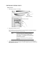
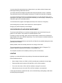
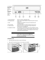
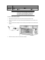
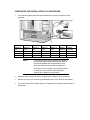
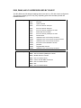
USING YOUR CD-ROM DRIVE
Your CD-ROM drive reads information or programs on a Compact Disc (CD). It cannot record
to a CD. To learn how to access information stored on a CD, refer to the documentation
supplied with the CD.
Your CD-ROM
drive may be
different from
the drive
shown here —
the
Headphones
Socket and
Volume
Control may
not be
present.
1. Open/Close Button
Opens or closes the CD-ROM drawer.
2. Emergency Eject
Used to open the CD-ROM drive mechanically when the power
supply is off.
3. Door
Protects the CD-ROM drive from dust contamination and
accidental damage.
4. Busy Indicator
Glows when the drive is ready and when the drive is busy.
5. Volume Control
Adjusts the volume of music played through headphones
connected to the CD-ROM drive.
6. Headphones Socket
Lets you listen to music CDs by connecting headphones directly
to the CD-ROM drive using a stereo mini-jack. (This does not cut
out the speakers.) Adjust the volume using the Volume Control,
and not using the audio software.
WARNING:
To avoid electrical shock and harm to your eyes
by laser light, do not open the CD-ROM drive
enclosure. The CD-ROM drive should be serviced
by service personnel only.
LOADING A CD
1
Press the Open/Close button to open the CD drawer.
2
Place the CD, label side facing up, in the recess in the drawer.
3
Press the Open/Close button to close the drawer. The drawer can also be closed by gently
pushing the drawer back into the drive.
4
To remove the CD, press the Open/Close button to open the drawer. Remove the CD.
Press the Open/Close button to close the drawer.
EJECTING A CD WHEN THE OPEN/CLOSE BUTTON IS DISABLED
If the Open/Close button is disabled by software or a power failure, use this procedure to
remove a CD:
1
Turn off the PC.
2
Insert a straight rod (for example, a straightened paper clip) into the emergency eject hole
next to the Open/Close button. The drawer should eject by about 15mm.
3
Pull out the drawer by hand until the CD can be easily removed.
4
Remove the CD.
5
Push the drawer gently back into the drive.
TIPS FOR USING YOUR PC
If you want to:
You need to:
• Install hardware accessories.
Refer to chapter 3 “How to Install Accessories Inside
Your PC”.
• Configure hardware accessories.
Refer to chapter 3 “How to Install Accessories Inside
Your PC”.
• Install new applications, and set up
and use an application.
Read the manuals supplied with the application
software.
• Make more disk space available.
Delete unnecessary files and increase disk space by
using a disk compression program.
Install a larger disk drive.
• Make more memory available.
Install more main memory. Refer to chapter 3.
• Display more colors.
Install more video memory. Refer to chapter 3.
• Stop anyone from starting the PC
in your absence.
Run the built-in Setup program and set a Password.
Refer to this chapter for details.
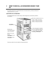
3
HOW TO INSTALL ACCESSORIES INSIDE YOUR
PC
This chapter explains how to install accessories, such as extra memory, accessory boards, and
additional disk drives, in your PC.
SUPPORTED HP ACCESSORIES
This chapter describes how to install memory, mass storage devices, and accessory boards in
your computer.
Main Memory Upgrades (ECC, 60 ns)
16 MB (2 X 8 MB), order D3553A
32 MB (2 X 16 MB), order D3555A
64 MB (2 X 32 MB), order D3554A
Internal Mass
Storage Devices
Mounting Trays:
3.5 inch disk drive trays,
5 pack, order D2037A
Rails for Front Access
Devices:
5.25 inch disk drive rails,
order D2880A
3.5 inch disk drive rails,
order D3566A
Contact your dealer for an up-to-date list of supported devices.
Front Access Drives, for example:
3.5 inch 1.44 MB flexible disk drive
(one third height), order D2035B
5.25 inch 1.2 MB flexible disk drive
(half height), order D2881B
Up to six accessory
boards can be installed:
three 32-bit PCI slots
two 16-bit ISA slots
one combination ISA
or PCI slot
WARNING:
For your safety, never remove the computer’s
cover without first removing the power cord and
any connection to a telecommunications
network. Always replace the cover before
switching on the computer.
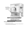
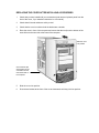
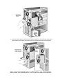
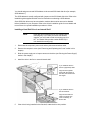
REMOVING AND REPLACING THE COVER
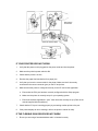
1
Switch off the display and computer.
2
Disconnect the power cords from the power outlets, computer, and display. Disconnect
any telecommunication cables from the computer.
Disconnect the power cords
3
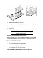
If necessary, unlock the cover using the key provided with the computer (the lock is on the
back of the computer).
4
Lift the two securing latches at the front of the computer.
Lift the securing
latches
5
Slide the cover forward until it is clear of the computer.
Slide the cover
clear of the
computer
If you have difficulty
removing the cover, try
pushing gently against
the CD-ROM drive with
your thumbs as you pull
the cover toward you
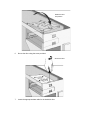
REPLACING THE COVER AFTER INSTALLING ACCESSORIES
1
Check that you have installed all your accessories (and removed a plastic panel from the
front of the cover, if you installed a disk drive in a front shelf).
2
Check that all internal cables are safely routed.
3
Check that the cover is unlocked and the latches are outwards.
4
Place the cover in front of the computer and ensure that the two lips at the bottom of the
case slide onto the two rails at the base of the computer.
Slide the cover
into position
Check that the lips
at the bottom of the
case slide onto the
rails at the base of
the computer
5
Slide the cover into position.
6
Push the two latches at the front of the cover downwards until they click into position.
Lock the cover
(at the back of
the computer)
7
If required, lock the cover using the key.
8
Reconnect all cables and power cables.
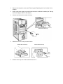
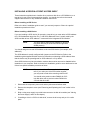
MOVING THE POWER SUPPLY
You can slide the power supply unit out of the computer to improve access to the system board
and the cables at the rear of the disk drives.
1
Disconnect the computer’s power cord and any telecommunications cable.
2
Remove the computer’s cover (see "Removing and Replacing the Cover" earlier in this
chapter).
3
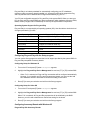
Unscrew the two self-retaining screws at the back of the power supply.
Push the
latches down
to secure the
cover
Unscrew the
self-retaining
screws
4
Using the small handle at the base of the power supply unit, slide the power supply out of
the computer until it stops—the power supply unit remains connected to the computer
Slide the power
supply unit clear
of the computer
Power
supply
REPLACING THE POWER SUPPLY AFTER INSTALLING ACCESSORIES
1
Check that all internal cables are safely routed.
2
Slide the power supply back into the computer.
3
Tighten the two self-retaining screws.
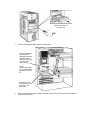
INSTALLING MEMORY
MAIN MEMORY MODULES
Your PC is supplied with main memory. If you need more main memory to run your application
software, you can install up to a total of 256 MB. Main memory upgrades are available in pairs
of 8 MB, 16 MB, or 32 MB.
Memory modules must be installed in identical pairs of the same size and same type (a pair of
ECC or a pair of non-ECC) from bank A, up to bank D. For a list of available memory modules,
refer to the beginning of this chapter.
If your PC supports ECC (error correcting code) memory, error correcting will be disabled if any
non-ECC memory is installed.
WARNING:
Static electricity can damage electronic
components. Turn all equipment OFF. Don’t let
your clothes touch the accessory.
To equalize the static electricity, rest the
accessory bag on top of the power supply while
you are removing the accessory from the bag.
Handle the accessory as little as possible and
with care.
To install a pair of main memory modules:
1
Disconnect the computer’s power cord and any telecommunications cable.
2
Remove the computer’s cover (see "Removing and Replacing the Cover" earlier in this
chapter). The location of the memory modules is shown here.
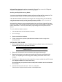
3
Slide each memory module into the slot at 90° to the system board (hold the memory
module with the cutouts closest to the processor).
Slide the memory module into the slot at 90°
Push the module until the retaining clips click
into position
4
Firmly press each memory module completely into the connector until the retaining clips
click into position.
5
Repeat this procedure for each pair of memory modules you are installing.
6
Install any other accessories before replacing the cover (see "Removing and Replacing
the Cover" earlier in this chapte). Reconnect all cables and power cords.
Completing the Main Memory Installation Procedure:
1
Switch on the PC. When Error 0250 appears (indicating that the Power-On-Self-Test
has detected a change in your memory configuration) follow the displayed instructions to
run the Setup program.
2
Check that Setup has automatically detected and configured the Memory Size fields.
Ensure the TOTAL memory is correct. If it is incorrect, check that you have correctly
installed the memory modules.
3
Set the extended memory limit field to Y if you use software designed for i286 processors
(or earlier processors) that cannot work with more than 16 MB total memory.
4
Press [F3] to save and exit the Setup program.
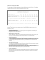
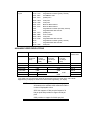
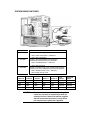
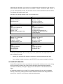
INSTALLING MORE MEMORY ON THE MGA VIDEO ADAPTER
If you need to have more video memory to display more colors, higher resolutions, or for
increased speed, you can install more video memory on the MGA Video Adapter (order
D3557A, 2 MB WRAM upgrade). Some of the available video resolutions are listed below
(refer to chapter 5 for more detailed information on video resolutions).
Resolution:
Video memory required for these colors:
256 colors
(8 bpp)
64 K colors
hi-color (16 bpp)
16.7 M colors
true-color (24 bpp)
16.7 M colors
true-color (32 bpp)
640 x 480
2 MB
800 x 600
2 MB
1024 x 768
2 MB
1280 x 1024
2 MB
WARNING:
4 MB
4 MB
8 MB
Static electricity can damage electronic
components. Turn all equipment OFF. Don’t let
your clothes touch the accessory. Handle the
accessory as little as possible and with care.
To install a video memory module:
1
Disconnect the computer’s power cord and any telecommunications cable.
2
Remove the computer’s cover (see "Removing and Replacing the Cover" earlier in this
chapter).
3
Remove the MGA video adapter from the accessory slot and place it on a static-free flat
surface.
4
Install the memory module on the MGA video adapter.
5
Replace the MGA video adapter in the computer.
6
Install any other accessories before replacing the cover (see "Removing and Replacing
the Cover" earlier in this chapter). Reconnect all cables and power cords.
Completing the Video Memory Installation Procedure
1
Switch on the PC.
2
Check that the Setup program has detected and configured the Video memory.
NOTE
If you need to use a special video driver for your
application, you may be asked to insert the CD-ROM
or diskette containing the driver.
Video Adapter accessories available from other sources
Additional accessories, including memory upgrades and a video MPEG module, are available
for your video adapter. However, these accessories cannot be ordered from HP. Contact your
dealer for more details about these accessories.
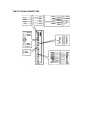
INSTALLING ACCESSORY BOARDS
The PC has six accessory board slots:
•
Slot 1 (the bottom slot) for full-length 16-bit ISA boards
•
Slot 2 for full-length 16-bit ISA boards
•
Slot 3 for either a full-length 32-bit PCI or a 16-bit ISA board
•
Slot 4 can be used for a full-length 32-bit PCI board
•
Slot 5 for a full-length 32-bit PCI board
•
Slot 6 (the top slot) for a full-length 32-bit PCI board.
CONFIGURING ACCESSORY BOARDS WITH PLUG AND PLAY
Plug and Play is an industry standard for automatically configuring your PC's hardware
resources and the accessory boards installed in it. Accessory boards which support the Plug
and Play standard can be detected and configured automatically by your PC.
Your PC has configurable support for Plug and Play in the system BIOS. When you start your
PC, the Plug and Play system BIOS can detect automatically which hardware resources (IRQs,
DMAs, memory ranges, and I/O addresses) are used by the system-based components.
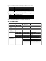
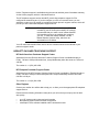
Operating System Support for Plug and Play
Plug and Play is not supported by all operating systems (OS). Use this table to check the level
of support provided by your OS.
Your Operating System
Level of Support for Plug and Play
Windows 3.11
Supported by ISA Configuration Utility (ICU)
Windows 95
Full support (integrated in OS)
Windows NT
None
OS/2 Warp
Support for PCMCIA cards only
SCO Unix
None
NextStep
None
Solaris
None
Configuring Plug and Play with the Setup program
You can use the Setup program to select the level of support provided by the system BIOS for
Plug and Play-compatible accessory boards.
Configuring Setup for Windows 95
1
Turn on the PC and press [F2] when <Setup=F2> appears.
2
Highlight the Plug and Play Device Management line and use [F7] or [F8] to select Full.
•
3
When Full is selected, all Plug and Play accessories will be configured automatically.
However, if you install a non-Plug and Play accessory board, you must use the Add
New Hardware wizard to determine a conflict-free setting for the board.
Press [F3] to save your selection and exit from the Setup program.
Configuring Setup for Other OS
1
Turn on the PC and press [F2] when <Setup=F2> appears.
2
Highlight the Plug and Play Device Management line and use [F7] or [F8] to select Full.
When Full is selected, all Plug and Play accessories will be initialized by the BIOS.
However, you will need to determine a conflict-free setting for the board.
3
Press [F3] to save your selection and exit from the Setup program.
Configuring Accessory Boards with Windows 95
Plug and Play ISA Accessory Boards
Windows 95 can detect and configure automatically Plug and Play accessories if Plug and
Play Device Management is set to Full in the Setup program.
Non-Plug and Play ISA Accessory Boards
You must run the Add New Hardware wizard to configure non-Plug and Play accessories. The
Add New Hardware wizard can identify automatically many accessory boards.
If the Add New Hardware wizard does not recognize the accessory board, you can manually
select the accessory board from a list of supported products. Windows 95 is preloaded with
configuration details for many non-Plug and Play accessory boards.
Windows 95 will determine the recommended settings for each ISA non-Plug and Play board
you want to install. These settings may be different from those recommended by the accessory
board’s manufacturer. In this case, the board’s jumper settings and driver options must be
altered.
To run the Add New Hardware wizard:
1
Click the Start button on the Windows 95 task bar.
2
Point to Settings.
3
Double-click Add New Hardware.
4
Follow the instructions provided by the Add New Hardware wizard to configure the
accessory board.
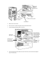
INSTALLING THE BOARD
1
Before installing the board, refer to "Installing Accessory Boards" earlier in this chapter for
important Plug and Play configuration information.
NOTE
PCI boards are configured automatically when
installed in the PC.
2
Disconnect the computer’s power cord and any telecommunications cable.
3
Remove the computer’s cover and power supply (see "Removing and Replacing the
Cover" and "Replacing the Power Supply after Installing Accessories" earlier in this
chapter).
4
Find a free slot. ISA boards should be installed in the lowest available slot and PCI boards
in the highest available slot to ease cable routing.
Some boards may have preferred locations and special installation instructions detailed in
their manuals.
5
Unscrew and remove the slot cover. Store it in a safe place.
If the slot cover is tight, loosen the screws on the adjacent slots.
Unscrew and remove
the slot cover
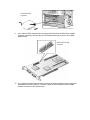
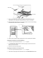
6
Hold the board horizontally by its “top” edge. Slide it into the board guide of the chosen
slot. Do not bend the board.
Slide the
accessory
board into
position
7
Align the board’s connector with the slot’s socket. Firmly press the board into the socket.
Ensure the board’s connector engages completely with the socket and does not touch
components on other boards.
8
Secure the board by replacing the slot cover screw.
If you loosened the screws on adjacent slots, tighten them.
Secure the board
in position
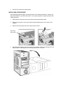
9
If you install a VESA-standard video accessory board that uses the MGA video adapter,
connect the accessory board’s cable to the VESA pass-through connector on the MGA
adapter board.
VESA Pass-Through
Connector
10
If you install a Creative Labs wavetable accessory board that operates with the integrated
SoundBlasterTM audio interface, connect the board’s interface cable to the wavetable
interface connector on the system board.
Wavetable interface
connector
11
Install any other accessories before replacing the cover (see "Replacing the Cover after
Installing Accessories" earlier in this chapter). Reconnect all cables and power cords.
Completing the Installation of an ISA Accessory Board
If you have installed an ISA accessory board that uses IRQ 9, 10, 11, or 15, you must run the
Setup program and reserve the IRQ for the accessory board. This allows PCI devices to be
automatically configured.
1
Turn on the PC and press [F2] when <Setup=F2> appears.
2
Highlight the IRQ field you want to change, for example IRQ 11.
3
Press [F7] or [F8] to make the IRQ available for PCI (Available for PCI) or make it
unavailable for PCI (Used by an ISA Board).
4
Press [F3] to save any changes you made and exit the SETUP program.
NOTE
You should always leave at least one IRQ available
for use by the integrated PCI devices.
INSTALLING DISK DRIVES
If you need extra mass storage space for your application software, you can install additional
mass storage devices.
The computer has two internal shelves (for hard disk drives) and five front-access drive
shelves (for front-access disk drives and hard disk drives).
Your computer is supplied with one 3.5-inch flexible disk drive and a CD-ROM drive. If your
computer is supplied with a hard disk, the hard disk will be installed in the first internal shelf.
two internal shelves
for 3.5-inch hard disks
two shelves for
3.5-inch disk drives
three shelves for
5.25-inch disk drives
INSTALLING A HARD DISK DRIVE
The computer has an integrated SCSI controller and an integrated Enhanced IDE controller.
•
The Enhanced IDE controller supports up to four IDE devices:
•
•
•
two IDE devices can be connected to the Primary Channel cable (connected to the
grey connector on the system board)
two IDE devices can be connected to the Secondary Channel cable (connected to the
red connector on the system board)
The SCSI controller supports up to seven SCSI devices
(up to five SCSI devices can be connected to the internal SCSI cable).
Before Installing an IDE Hard Disk
Refer to the drive’s installation guide to see if you must set jumpers or if there is a special
installation procedure to follow.
Before Installing a SCSI Hard Disk
If you are installing an additional SCSI drive you must select a SCSI address for the new drive.
SCSI addresses range from 0 to 7, with SCSI address 0 used by the first SCSI drive and SCSI
address 7 reserved for the integrated SCSI controller.
NOTE
You don’t need to select a SCSI address for Plug and
Play SCSI hard disks (SCSI hard disks which support
the SCAM protocol).
You should assign an unused SCSI address to the second SCSI hard disk drive (for example,
SCSI address 1).
The SCSI address is usually configured with jumpers on the SCSI hard disk drive. Refer to the
installation guide supplied with the drive for information on selecting a SCSI address.
Some SCSI disk drives may have termination resistors that must be removed or disabled
before installation in your computer. Refer to the drive’s installation guide for more details and
to see if there is a special installation procedure to follow.
Installing a Hard Disk Drive in an Internal Shelf
NOTE
Hard disk drives ordered from HP are supplied with a
mounting tray. If you order your drive from another
supplier, you may need to order a mounting tray from
HP. You should order product number D2037A (3.5inch hard disk mounting tray).
1
Disconnect the computer’s power cord and any telecommunications cable.
2
Remove the computer’s cover (see "Removing and Replacing the Cover" earlier in this
chapter).
3
Slide the power supply out to improve access to the drive (see "Moving the Power Supply"
earlier in this chapter).
4
Install the drive in the first or second internal shelf.
If you install the drive in
the first (uppermost) shelf:
Align the drive (upside
down) with the hinges on
the shelf, then insert it into
the hinges
If you install the drive in
the second shelf:
Align the drive with the
slots in the shelf, then
insert it carefully, as
shown here
5
If the drive is being installed in the first shelf, rotate the drive into position.
Rotate the drive
into position
6
Secure the drive using the screw provided.
Secure the drive
7
Locate the appropriate data cable for the hard disk drive.
IDE drives should be
connected to the
Primary IDE Channel
cable (this cable is
connected to the grey
connector on the
system board)
NOTE
The IDE data cables
are in a bag supplied
separately with your
PC
SCSI drives can be
connected to any free
connector on the
SCSI cable
8
Connect the power cable and the data cable to the rear of the drive. (The connectors are
shaped to go in one way only.)
Power Cable
Data Cable
9
Install any other accessories before completing the installation.
10
See "Completing the Installation of a Hard Disk Drive" later in this chapter to complete the
installation.
Installing a Hard Disk Drive in a Front-Access Shelf
1
Disconnect the computer’s power cord and any telecommunications cable.
2
Remove the computer’s cover (see "Removing and Replacing the Cover" earlier in this
chapter).
3
Slide out the power supply to provide better access to the disk drive cables (see "Moving
the Power Supply" earlier in this chapter).
4
Unscrew and remove an unused drive tray.
Remove the drive tray
5
Mount the drive on the tray as shown below.
Set the drive on the tray
6
Fix the drive to the tray
Slide the drive tray into the drive shelf and secure it.
Slide the drive tray into
the drive shelf
7
Locate the appropriate data cable for the disk drive.
IDE drives should be
connected to the
Primary IDE Channel
cable (this cable is
connected to the grey
connector on the
system board)
NOTE
The IDE data cables
are in a bag supplied
separately w ith your
PC
SCSI drives can be
connected to any free
connector on the
SCSI cable
8
Connect the data and power cables to the rear of the device. (The connectors are shaped
to go in one way only.)
Data Cable
Power Cable
9
Slide the power supply back into position, and tighten its self-retaining screws (see
"Replacing the Power Supply after Installing Accessories" earlier in this chapter).
10
Install any other accessories before replacing the cover and completing the installation.
11
"Completing the Installation of a Hard Disk Drive" later in this chapter to complete the
installation.
COMPLETING THE INSTALLATION OF A HARD DISK DRIVE
When a SCSI Drive is Installed
1
Switch on the computer.
2
When the SCSI BIOS initialization messages are displayed, check that the details for the
new SCSI drive have been correctly detected.
Refer to the operating system documentation for information on formatting a drive.
When an IDE Drive is Installed
1
Switch on the computer.
2
When an error message appears, follow the instructions provided by the Error Message
Utility. When prompted, press [F2] to run the Setup program.
3
In the IDE Primary Channel (or IDE Secondary Channel) section, check that the details
for Device 1 (or Device 2) have been correctly detected by the Setup program.
4
Press [F3] to save and exit Setup.
Refer to the operating system documentation for information on formatting a drive.
NOTE
If an IDE drive is removed, switch on the computer
and follow the instructions displayed by the Error
Message Utility. When prompted, press [F2] to run
the Setup program and select None or SCSI for the
missing drive.
INSTALLING A DRIVE IN A FRONT-ACCESS SHELF
These instructions explain how to install a drive (such as a disk drive, a CD-ROM drive, or a
tape drive) in one of the front-access drive shelves. You should also refer to the manual
supplied with the drive for any additional installation instructions.
Before Installing an IDE Device
Refer to the drive’s installation guide to see if you must set jumpers or if there is a special
installation procedure to follow.
Before Installing a SCSI Device
If you are installing a SCSI device (for example, a tape drive) you must select a SCSI address
for it. SCSI addresses range from 0 to 7, with SCSI addresses 0 and 1 usually used by the
SCSI hard disk drives. SCSI address 7 is reserved for the integrated SCSI controller.
NOTE
You don’t need to select a SCSI address for Plug and
Play SCSI devices (SCSI devices which support the
SCAM protocol).
You should assign an unused SCSI address to the new SCSI device (for example, SCSI
address 2).
The SCSI address is usually configured with jumpers on the SCSI device. Refer to the
installation guide supplied with the device for information on selecting a SCSI address. Note
that the device may be preconfigured for SCSI address 2 or 3 by default.
Some SCSI devices may have termination resistors that must be removed or disabled before
installation in your computer. Refer to the device’s installation guide for more details and to see
if there is a special installation procedure to follow.
NOTE
Drives ordered from HP are supplied with mounting
rails. If you order your drive from another supplier,
you may need to order drive mounting rails from HP.
You should order product number D2880A for 5.25inch disk drive rails or product number D3566A for
3.5-inch disk drive rails.
1
Disconnect the computer’s power cord and any telecommunications cable.
2
Remove the computer’s cover (see "Removing and Replacing the Cover" earlier in this
chapter).
3
Slide out the power supply to provide better access to the disk drive cables (see "Moving
the Power Supply" earlier in this chapter).
4
If installing a drive in a 5.25-inch wide shelf, remove the drive tray and put it in a safe
place.
Remove; the
drive tray if
installing a
5.25-inch drive
Slide the drive into position
Secure the drive
in position
Mounting Rails
5
Slide the drive into the shelf.
6
Secure the drive in position using the screws provided with the drive.
7
Locate the appropriate data cable for the device
Flexible Disk
Drive Cable
SCSI devices can
be connected to
any free connector
on the SCSI cable
8
IDE CD-ROM drives
should be connected
to the Secondary IDE
Channel cable (this
cable is connected to
the red connector on
the system board)
NOTE
The IDE data cables
are supplied
separately in a bag
with your PC
Connect the data and power cables to the rear of the device. (The connectors are shaped
to go in one way only.)
Data Cable
Power Cable
9
Slide the power supply back into position, and tighten its self-retaining screws (see
"Replacing the Power Supply after Installing Accessories" earlier in this chapter).
10
Remove the plastic panel from the cover by pulling the panel from the left and unhinging
its right-hand side. Store the panel in a safe place.
Unclip and lift out the plastic panel
11
Install any other accessories before replacing the cover and completing the installation.
Completing the Installation of an IDE CD-ROM drive
1
Turn on the computer and press [F2] when <Setup=F2> appears.
2
In the IDE Secondary Channel section of the Setup program, make sure that the CDROM drive has been detected.
3
Press [F3] to save and exit the program.
Completing the Installation of a Flexible disk drive
1
Turn on the computer and press [F2] when <Setup=F2> appears.
2
Check that the Setup program has detected the drive in the Flexible Disk Drives section.
3
Press [F3] to save and exit the program.
INSTALLING A PROCESSOR
Some operating systems support a second processor for increased performance. Contact your
authorized reseller for up-to-date information. You may also replace the original processor with
a faster processor.
1
Disconnect the computer’s power cord and any telecommunications cable.
2
Remove the computer’s cover (see "Removing and Replacing the Cover" earlier in this
chapter).
3
Remove the airflow guide from above the processor socket.
Remove the
airflow guide
4
Move the power supply to improve access to the processor socket (see "Moving the Power
Supply" earlier in this chapter), then carefully place the PC on its side.
5
Install the VRM module supplied with the processor.
6
Unlock the processor socket and position the processor over it.
7
Insert the new processor into the socket and lock the processor into place.
Insert the processor
into the socket
8
Place the heatsink on the processor and attach the retaining clips to the processor socket.
Attach the
heatsink to the
socket
9
Carefully set the PC in the upright position.
10
Slide the power supply back into the computer and tighten the two self-retaining screws.
11
Replace the airflow guide above the processor socket.
COMPLETING THE INSTALLATION OF A PROCESSOR
1
Verify that the system board bus speed switches are correctly configured for the
processor.
Switch 4
Switch 5
Switch 6
Switch 7
Switch 8
Bus
Speed
Processor
Speed
ON
OFF
ON
OFF
OFF
60 MHz
150 MHz
OFF
OFF
ON
OFF
OFF
66 MHz
166 MHz
ON
OFF
OFF
ON
OFF
60 MHz
180 MHz
OFF
OFF
OFF
ON
OFF
66 MHz
200 MHz
NOTE
If two processors are installed, both must operate at
the same bus speed and processor speed. Refer to
the manual supplied with the processor to verify
which bus and processor speeds are supported.
Note that you must configure your operating system
to use the second processor. Some operating
systems do not support two processors.
1
Install any other accessories before completing the installation of the processor.
2
Replace the cover (see "Removing and Replacing the Cover" earlier in this chapter).
3
Turn on the computer and check that the new processor is recognized by the power-on
system-test.
4
TROUBLESHOOTING YOUR PC AND USING THE
SETUP PROGRAM
This chapter can help you solve problems that you may encounter when using your PC and
describes how to use the HP Setup program.
SOLVING PROBLEMS
If you have a problem with your PC, search the list below for the problem description which
most closely matches it. Then turn to the page indicated for guidance.
If Your PC Does Not Start
•
If nothing appears on your display, see "If Your PC Does Not Start" in this chapter.
•
If an error message appears:
•
If a System ROM message appears, see "If an Error Message Appears" in this
chapter.
•
If a Power-On-Self-Test error appears, see "If an Error is Detected by the Power-OnSelf-Test" in this chapter.
•
If a Power-On-Self-Test error prevents your PC from starting, see "If an Error is
Detected by the Power-On-Self-Test" in this chapter.
•
If a BIOS message prevents your PC from starting, see "BIOS Error Messages that
May Prevent Your PC From Starting" in this chapter.
•
If an Operating System message prevents your PC from starting, see "Operating
System Messages that May Prevent Your PC From Starting" in this chapter.
If Your PC Has a Hardware Problem
•
If your display does not work, see "If Your Display Does Not Work" in this chapter.
•
If you cannot set any video resolution higher than 640 5 480, see "If You Cannot Use
Any Video Resoluton Higher Than 640 X 480" in this chapter.
•
If your keyboard or mouse does not work, see "If Your Keyboard or Mouse Does Not
Work" in this chapter.
•
If your printer does not work, see "If Your Printer Does Not Work" in this chapter.
•
If the flexible disk drive does not work, see "If the Flexible Disk Drive Does Not Work" in
this chapter.
•
If the hard disk does not work, see "If the Hard Disk Does Not Work" in this chapter.
•
If the hard disk activity light does not work, see "If the Hard Disk Activity Light Does
Not Work" in this chapter.
•
If an accessory board does not work, see "If an Accessory Board Does Not Work" in this
chapter.
If Your PC Has a Software Problem
•
If you have forgotten your passwords, see "If You Have Forgotten Your Password" in this
chapter.
•
If you can’t start the Setup program, "If You Can't Start the Setup Program" in this chapter.
•
If the date and time are incorrect, "If the Date and Time Are Incorrect" in this chapter.
If Your PC Has a Networking Problem
•
Use the HPVGSET utility (provided on the “XU/VT Drivers and Documentation” CD-ROM)
to troubleshoot your network adapter.
The HPVGSET utility is described in the Network Administrator’s Guide on the “XU/VT
Drivers and Documenation” CD-ROM.
IF YOU CANNOT SOLVE THE PROBLEM
If you are unable to solve your problem after following the troubleshooting advice in this
chapter, refer to chapter 6, HP Support and Information Services, for information on getting
help from your HP Reseller or from your nearest HP Customer Support Center.
IF YOUR PC DOES NOT START
IF YOUR DISPLAY IS BLANK AND THERE ARE NO ERROR MESSAGES
1
Make sure that all cables and power cords are firmly plugged in.
2
Make sure the power outlet is working.
3
Check that the computer and display are turned on. (The power light should be
illuminated.)
4
Check the display’s contrast and brightness settings.
5
If the PC still does not work:
a
Turn off the display, the computer, and all external devices.
b
Unplug all power cords and cables, noting their positions.
c
Remove the cover (refer to "Removing and Replacing the Cover" in chapter 3).
d
Check that the processor is correctly installed (refer to "Installing a Processor" in
chapter 3).
e
Check that the memory modules are correctly installed (refer to "Installing Memory" in
chapter 3).
f
Check that accessory boards are firmly seated in their slots (refer to "Installing
Accessory Boards" in chapter 3).
g
Verify that any switches and jumpers on the accessory boards are properly set (refer
to the manuals that came with each board).
h
Check that the switches on the system board are properly set (refer to "System
Connectors and Switches" in chapter 5).
i
Replace the cover (refer to "Replacing the cover After Installing Accessories" in
chapter 3).
j
Connect all cables and power cords (refer to chapter 1).
k
Turn on the display and computer.
If your PC still does not start, remove all boards and accessories, except the hard disk drive.
Start the PC. If the PC now works, add the boards and accessories one at a time to determine
which one is causing the problem.
IF AN ERROR MESSAGE APPEARS
If a System ROM Message Appears
If the following system ROM error message appears:
Cannot display error messages
Flash ROM may be defective
the contents of the system ROM are corrupted or incomplete, and you will need to update the
system BIOS using the HPInit utility.
Contact your HP reseller (or your HP sales office) to get an HPInit utility diskette and the latest
system BIOS for your PC by mail.
NOTE
Please specify the model number of your HP Vectra
PC when ordering the HPInit utility and the latest
system BIOS.
If you have access to a PC with a modem or network
connection, which functions correctly, you can
retrieve the latest system BIOS from one of the HP
Information Services described in chapter 6, HP
Support and Information Services.
To update the system BIOS:
1
Insert the HPInit utility diskette in drive A.
2
Switch the computer OFF and then ON, and follow the instructions until the procedure
finishes. Do NOT switch off the computer until the system BIOS update procedure has
completed (successfully or not) since irrecoverable damage to the ROM may occur.
3
Remove the HPInit utility diskette.
4
Switch the computer OFF and then ON to initialize the system ROM.
If an Error is detected by the Power-On-Self-Test
If an error is detected when the PC starts, the Error Message Utility (EMU) is launched.
•
Follow the instructions provided by the EMU.
•
If prompted by the EMU, press [F2] to run Setup and correct the error (refer to "Using the
HP Setup Program" in this chapter for information on using Setup).
•
Press [F1] to continue and ignore the error. (It is recommended that you fix the error
before proceeding, even if the PC appears to start successfully.)
Corrective actions for errors that may prevent your PC from starting are described in the
following table.
Power-On-Self-Test Errors that May Prevent Your PC From Starting:
0130,
0241
0280
What you should do:
1 Ensure the configuration stored in CMOS memory has not been cleared by the
system board switch (refer to chapter 5).
2 Run Setup to correct the configuration information.
3 If all the above fail to correct the problem, the system board may need to be replaced.
Contact your service representative.
0250
What you should do:
1 Run Setup and correct the errors highlighted by the Setup program.
2 Ensure the configuration stored in CMOS memory has not been cleared by the
system board switch (refer to chapter 5). Make a written note of the configuration.
3 If the hardware was changed, run Setup to update the configuration information.
06xx
What you should do:
1 Ensure that nothing is pushing down on the keyboard, and that no key is stuck down.
2 If the problem persists, contact your service representative.
61xx,
6500,
6510,
6520
8x06
What you should do:
1 Ensure the memory modules are installed correctly (refer to chapter 3).
2 If this does not fix the problem, initialize the system ROM (refer to “If You Can’t Start
the Setup Program” in this chapter on page 103).
3 If the problem persists, the system board may need to be replaced. Contact your
service representative.
65xx,
66xx
What you should do:
1 Disable all shadowing with the Setup program.
2 If this fails to correct the problem, the system board may need to be replaced. Contact
your service representative.
8060
What you should do:
1 Check that the hard disk drive has not been disabled with the Setup program.
2 Check that the disk power and data cables are correctly connected (refer to chapter
3).
910B
Explanation:
1 You connected the flexible disk drive connector B to the disk drive, and there is no
connection to a drive A.
2 Change the flexible disk drive connector to A (refer to chapter 3).
BIOS Error Messages that May Prevent Your PC From Starting:
Cannot start from
hard disk (A new
drive may need to be
partitioned and
formatted).
For more information
refer to your
manual. To continue
without an explanation, just press F1.
Insert system
diskette in drive.
Press any key to
continue.
Explanation:
There is no operating system installed on your hard disk.
What you should do:
Install an operating system on the hard disk or insert a diskette
with an operating system, and press any alphanumeric key to
continue.
Refer to chapter 1 of this User’s Guide for instructions on installing
an operating system.
Explanation:
•
there is no operating system installed on your hard disk
•
there is no operating system on the diskette in drive A
•
the hard disk drive is disabled, or not present.
What you should do:
Install an operating system on the hard disk or insert a diskette
with an operating system, and press any alphanumeric key to
continue.
Refer to chapter 1 of this User’s Guide for instructions on installing
an operating system.
Boot program in
first sector of
diskette is invalid,
cannot start from
this diskette.
Cannot start from
hard disk.
Missing operating
system
Explanation:
There is a problem with the disk drive, or the disk drive is not
properly formatted.
What you should do:
Insert a diskette with the proper operating system, and press any
alphanumeric key to continue.
Explanation:
You tried to start the PC but the PC could not find the operating
system.
What you should do:
Run Setup and make sure the hard disk has been correctly
configured.
System boot process
failed. Press any
key to try again.
Explanation:
You tried to start the PC but the PC could not find the operating
system.
What you should do:
•
check the diskette contains the operating system
•
check the hard disk contains the operating system
•
ensure “start from the flexible disk” or “start from the hard
disk” is enabled in Setup
•
for a network, ensure “remote start” is enabled in Setup.
Operating System Messages that May Prevent Your PC From Starting:
Non-system disk
or disk error
What you should do:
Not ready error
reading (or
writing) drive x
Explanation:
Remove the diskette, or replace it with the
proper operating system diskette, and press
any alphanumeric key to continue.
The device specified in the error message is
not ready to accept or transmit data. This
could occur if:
• The diskette has not been inserted correctly.
If this is the problem, reinsert the diskette and
type ‘‘R’’ (for Retry).
• The printer is not working—ensure it is on
and ready to print.
• The device has been disabled using Setup.
IF YOUR PC HAS A HARDWARE PROBLEM
This section describes what to do if you have problems with your display, disk drives, printer,
accessory boards, keyboard, or mouse.
IF YOUR DISPLAY DOES NOT WORK
If nothing is displayed on the screen, but the PC starts and the keyboard, disk drives, and other
peripheral devices seem to operate properly:
1
Check that the brightness and contrast controls are properly set.
2
Make sure that the display is plugged in and switched ON.
3
Ensure that the display video cable is correctly connected to the display and to the PC.
4
Switch off the display, and unplug it from the power outlet. Examine the video cable pins
to see if they are bent. If they are, carefully straighten them.
If the display image is not aligned with the screen (usually when you change resolutions), use
the display’s controls to center the image. Refer to the display manual for instructions.
If the screens generated by your software applications do not appear correct, check the
application’s manual to find out which video standard is required. Also check your display
manual to find out which refresh rate is required. Use the HP User Tools (in Windows 95 only)
or the Setup program to select the correct refresh rate.
If the display works correctly during the Power-On-Self-Test (POST), but goes blank when the
operating system starts:
•
Restart the PC and check that the amount of video memory detected by the POST is
correct. If you have installed extra video memory and only 2 MB is detected, check that
the video memory module is installed correctly on the video accessory board (see
"Installing More Memory on the MGA Video Adapter" in chapter 3).
•
If the video memory is correctly detected by the POST, follow the instructions below to
correct the problem.
If You Cannot Use Any Video Resolution Higher Than 640 X 480
If you cannot select a video resolution higher than 640 X 480, you should clear the contents of
the CMOS memory.
To clear the configuration:
1
Switch off the PC and remove the cover (refer to chapter 3 for instructions).
2
Set the system board switch 1 (CONFG) on the switch block to ON to clear the
configuration from the CMOS memory (refer to "System Board Switches" in chapter 5 for
the switch location).
3
Switch on the PC to erase the CMOS memory.
4
Check that error codes 0240 and 0130 are displayed by the Error Message Utility, and wait
until the PC has started.
5
Switch off the PC.
6
Set the system board switch 1 (CONFG) on the switch block to OFF to re-enable the
configuration.
7
Replace the cover (refer to chapter 3).
8
Switch on the PC and run Setup by pressing [F2] when <Setup=F2> appears. (Error code
0130 will appear when the PC starts.)
9
Press [F3] to save the configuration and exit from Setup.
IF YOUR KEYBOARD OR MOUSE DOES NOT WORK
1
Ensure that the keyboard or mouse is correctly connected.
2
Ensure that the mouse driver supplied with the preloaded software is installed correctly.
(Choose a Logitech™ mouse driver for your operating system.)
3
Clean the mouse ball and rollers as shown in the figure below (use a non-residual contact
cleaner).
Remove the
mouse ball
Clean the mouse rollers
Clean the mouse ball
IF YOUR PRINTER DOES NOT WORK
1
Verify that the power cord is plugged into the power outlet and into the printer.
2
Make sure the printer’s power switch is ON.
3
Check that the printer is on-line.
4
Examine the paper feed mechanism for a paper jam.
5
Verify that you have the correct cable for the printer. Make sure that it is securely
connected to the correct connector (port) on the PC and printer.
6
Make sure that the printer is configured correctly for the PC and for the application.
a
Ensure that the PC’s port has been correctly configured with the Setup program.
b
Make sure the printer is correctly set up for your operating system.
c
Ensure the software application’s “print” menu has been correctly set up. (Refer to the
manual supplied with the software.)
7
Check that the PC’s port is working properly by connecting another printer to the port.
8
If the printer displays an error message, refer to the printer’s manual for help.
IF THE FLEXIBLE DISK DRIVE DOES NOT WORK
1
Ensure you are using a formatted diskette and it is inserted correctly.
2
Check you are using a diskette that is the right density. You should use only 1.44 MB High
Density diskettes in drive A (High Density diskettes have a HD symbol printed on the
diskette).
3
Check that the flexible disk drive has not been disabled in Setup (refer to "Using the HP
Setup Program" in this chapter).
a
There are two options in the Security Features section of Setup which may be used
to disable or enable:
• the flexible disk drives
• writing to flexible disks.
b
There is one option in the Start-Up Center which may be used to disable or enable:
• start (boot) from flexible disks
4
Check that the disk power and data cables are correctly connected (refer to chapter 3).
5
Clean the flexible disk drive using a “wet-cleaning diskette kit” (this kit may be purchased
from most resellers).
IF THE HARD DISK DOES NOT WORK
1
Check that the hard disk drive has not been disabled in Setup (refer to "Using the HP
Setup Program" in this chapter).
•
There is an option in the Security Features section of Setup which may be used to
disable or enable the hard disk drives
•
the Start-Up Center may be used to disable or enable starting from hard disk.
2
Check that the disk power and data cables are correctly connected (refer to chapter 3).
3
Check that power management has been correctly configured.
If the Hard Disk Activity Light Does Not Work
If the hard disk activity light does not flicker when the PC is accessing the hard disk drive:
1
Check that the control panel connector is firmly attached to the system board.
2
Check that the disk power and data cables are correctly connected (refer to chapter 3).
IF AN ACCESSORY BOARD DOES NOT WORK
Perform the following checks:
1
Ensure the board has been firmly installed in the accessory board slot (refer to chapter 3)
2
Ensure the board is not using memory, I/O addresses, an IRQ, or DMA also used by the
PC. Refer to the board’s manual for details.
3
Check that the PC has been configured correctly in Setup.
4
If the problem persists, contact the accessory board vendor.
IF YOUR PC HAS A SOFTWARE PROBLEM
IF YOU HAVE FORGOTTEN YOUR PASSWORD
•
•
If you forget the User Password and the System Administrator Password is set and known:
1
Restart the PC. If the keyboard is locked, unplug the power cord and plug it in again.
2
Wait for the message <F2=Setup>.
3
Press [F2] to start Setup.
4
Type the System Administrator Password to enter Setup.
5
Highlight the User Password field and set a new User Password.
6
Press [F3] to save the new User Password and exit Setup.
If you forget both the User Password and the System Administrator Password:
1
Switch off the PC.
2
Remove the computer’s cover (refer to chapter 3).
3
Set switch 2 (PSWRD) on the system board switch block to ON (refer to chapter 5 for
the switch location).
4
Switch on the PC and allow it to complete its startup routine.
5
Switch off the computer.
6
Reset switch 2 (PSWRD) to OFF.
7
Replace the computer’s cover (refer to chapter 3).
8
Switch on the PC and allow it to complete its startup routine.
9
Press [F2] when prompted to use Setup.
10 Set new User and System Administrator Passwords.
11 Press [F3] to save the new passwords and exit Setup.
IF YOU CAN’T START THE SETUP PROGRAM
This may happen if the copy of the PC’s configuration stored in memory is corrupted. You will
need to erase this bad configuration.
To clear the configuration:
1
Switch off the PC and remove the cover (refer to chapter 3).
2
Set the system board switch 1 (CONFG) on the switch block to ON to clear the
configuration (refer to "System Connectors and Switches" in chapter 5 for the switch
location).
3
Switch on the PC to erase the memory.
4
Check that error codes 0240 and 0130 are displayed, and wait until the PC has started.
5
Switch off the PC.
6
Set the system board switch 1 (CONFG) on the switch block to OFF to re-enable the
configuration.
7
Replace the cover (refer to chapter 3).
8
Switch on the PC and run Setup by pressing [F2] when <Setup=F2> appears. (Error code
0130 will appear when the PC starts.)
9
Press F[3] to save the configuration and exit from Setup.
IF THE DATE AND TIME ARE INCORRECT
The date and time can be incorrect for the following reasons:
•
the time has changed for the seasons
•
the PC has been unplugged from the power too long, and the Gold Capacitor which
supplies power to the CMOS memory has discharged.
Use the Setup program to change the date and time.
IF YOUR PC HAS AN AUDIO PROBLEM
No Sound When Running Any Applications
First, check that the output volume is not set to zero. Use the volume control on the front panel.
Make sure the headphones are not connected directly to the CD-ROM drive (see the
connection information in chapter 1).
Remember also that plugging the headphones into the front panel cuts out sound to the internal
speaker and to external speakers connected to the audio Stereo Out jack.
When your PC starts up, the integrated audio interface may have no IRQ or DMA settings.
These settings are initialized by software upon startup. Your system files may not have the
necessary entries. Run the Setup program to configure the IRQ and DMA settings.
Absence of sound can also be caused by a hardware conflict. Hardware conflicts occur when
two or more peripheral devices compete for the same signal lines or channels. Conflicts
between your audio interface and another peripheral device might be due to the settings of the
I/O addresses, IRQ channel, or DMA channel. To resolve the conflict, change the settings
either of the audio interface or of any other ISA accessory in your system.
No Output from the 8-bit or 16-bit Digitized Sounds
This might be due to the DMA channel selected. If you hear no output from both the 8-bit and
16-bit digitized sounds, this might be due to an interrupt conflict. Use the HP Setup program or
your operating system’s audio control software to change the audio interface’s DMA channel or
IRQ setting.
The Volume is Too Low
The computer has two output jacks, Stereo Out on the rear of the computer and a headphones
jack on the front panel, which provide the same output signal. This is a low-distortion output
that cannot drive (without amplification) low-impedance devices such as speakers. If you plug
devices with a low-impedance (less than 32 ohms) into the Stereo Out jack or the headphones
jack, the volume will be low.
Audio Input from the Microphone is Too Low, or No Audio At All
Check that the microphone specifications meet the requirements of the 16-bit sound
components. The microphone should be a 600-ohm dynamic type.
Humming Noise
If the power grounding of your audio components is inadequate, a humming noise may be
generated. This may happen if your PC is connected to a hi-fi system. Plug all devices into
adjacent power outlets (outlets within 5 cm / 2 inches of each other), or use line filters.
Occasional Crackles When Playing Back Sounds
These crackles are usually the result of your PC being unable to transfer audio samples within
the required time. A solution is to use a lower sampling rate. Recording and playing back at 22
kHz is less demanding upon system resources than recording audio at 44 kHz.
The PC Hangs While Recording
Uncompressed digital audio can eventually fill your hard disk. For example, one minute of
stereo sound recorded at a resolution of 44 kHz will occupy about 10.5 MB. Before recording,
check that there is enough free space on your hard disk.
Data compression can reduce the space required. The A-law and m-law hardware compression
used by the audio interface enables the sampling of sound at a resolution of 16-bits, but it
generates the same quantity of data as an 8-bit sample.
MS-DOS Games Give “Not enough memory” Errors
Many games require a large amount of base memory and may not execute if many drivers or
TSR (Terminate and Stay Resident) programs are installed. You may solve this problem by
loading device drivers and TSRs into high memory. Refer to your MS-DOS manual for details
of how to do this.
IF THE CD-ROM DRIVE HAS A PROBLEM
Check that the software is correctly installed and the system correctly configured before
removing your computer’s cover to check the CD-ROM cable connections and jumper settings.
No Sound from the CD-ROM Drive
If you are having problems with sound when playing a CD:
•
Check that the volume control (if present) on the CD-ROM drive front panel is not set to
the minimum.
•
Ensure that the disk in the CD-ROM drive is an audio disk and not a Photo CD or data CD.
•
If using headphones or external speakers, check that they are properly connected (see
chapter 1).
•
Check that the CD audio cable is correctly installed and is connected to the system board.
CD-ROM Drive is Idle
If the CD-ROM drive does not appear to be working, try accessing the disk by clicking on the
CD-ROM drive icon or drive letter assigned to the CD-ROM drive by your operating system.
WARNING:
Be sure to disconnect the power cord from your
computer before you remove the cover to check
the cable connections or jumper settings.
USING THE HP SETUP PROGRAM
Setup is an integrated (ROM-based) program that displays the PC’s configuration.
Configuration information for associated PC features is grouped together to make it easier to
find.
Check the configuration when you first use the PC and each time after you install, remove, or
upgrade accessories.
NOTE
If you are unable to change the PC’s configuration,
check that you entered the correct password when
you started Setup.
STARTING THE SETUP PROGRAM
1
Turn on the PC and the display.
If the PC is already turned on, save your data and exit all programs, then press [CTRL]
[ALT] and [DELETE] to restart the PC.
2
Press [F2] while <Setup=F2>is displayed on the screen.
<Setup=F2>
<Setup=F2> appears for only a few seconds, just after the beeps signalling the end of the selftest.
3
The PC’s Setup program will appear.
System BIOS (Version x.xx.xx)
Video Adapter (MGA Millenium 2 MB, Video BIOS version xx.xx)
System Board (Pentium™) Pro, XXX MHz)
Memory (xx MB, 640 KB base, 384 KB Reserved, XX Ext.)
Hard Disk Drives (No IDE disk detected)
LAN (100VG, MAC address: 1234567890)
•
To change a setting, move the highlight to the desired line and follow the instructions
on the bottom of the screen.
•
Use the ↑ or ↓ keys to move the highlight from one line to another.
•
Use the [F7] or [F8] key to display available values.
•
Use the [NUM LOCK] key to set the numeric keypad to cursor control or numerics.
•
Use the [HOME] key to display the first Setup screen.
•
Use the [F1] key to display help (press it again to turn the help off).
•
Use the [F3] key to save your settings and exit Setup.
•
Use the [F10] key to print the Setup configuration.
•
Use the [F12] key to exit Setup without saving any changes.
UNDERSTANDING THE SETUP PROGRAM
This section of the book only explains the important Setup options that are not described
elsewhere in this User’s Guide.
The built-in Setup program is accessed by pressing [F2] during the PC’s Power-On-Self-Test.
For more information about Setup options, highlight an option and press [F1] for contextsensitive online help. If you have a printer connected to your computer, press [F10] to print out
the current Setup configuration.
NOTE
The Setup options displayed on your screen may be
different from those described here.
Viewing the Configuration Screen
This screen provides information about your computer’s configuration. These items are for
information only and cannot be changed.
Setup (Version x.xx.xx)
F1=Help On/Off
System BIOS (Verxion x.xx.xx)
Video (MGA Millenium 2 MB, Video BIOS version xx.xx)
System Board (Pentium™) Pro, XXX MHz)
Memory (xx MB, 640 KB base, 384 KB Reserved, XX Ext.)
Hard Disk Drives (No IDE disk detected)
LAN (100VG, MAC address: 1234567890)
Optimizing the System BIOS
Highlight the Operating System option and select the name of the operating system installed
on your computer. The system BIOS will be optimized for your operating system.
Date (Year/Month/Day) . . . . . . . . . 1995 / 01 / 01
Time (Hour/Minute/Second) . . . . . . . 09 : 35 : 53
Operating System . . . . . . . . . . . . Microsoft Windows NT
Changing User Preferences
Some of the User Preferences options will not be available if you have selected Operating
System . . Windows 95.
Highlight the Keyboard Power On option and select Enabled if you want to use the space bar
on your keyboard to switch on your computer.
User Preferences
User Password . . . . .
Keyboard Lock Timer . .
Screen Blanking . . . .
Key Autorepeat Speed .
Delay before Autorepeat
Power-on Numlock State
Keyboard Power On . . .
Memory Test . . . . . .
.
.
.
.
.
.
.
.
.
.
.
.
.
.
.
.
.
.
.
.
.
.
.
.
.
.
.
.
.
.
.
.
.
.
.
.
.
.
.
.
Not Set/Set
Disabled/Enabled
Enabled/Disabled
2 to 30 per second
0.25 to 1 second
Not Set/Set
Disabled/Enabled
Disabled/Enabled
To speed up the computer’s power-on self-test, highlight Memory Test and select Disabled
Viewing Processor Information
These lines provide information about the processor installed in your computer (and cannot be
changed).
Processor . . . . . . . . . . . . . . Pentium Pro
Computer Speed . . . . . . . . . . . 150 MHz
Coprocessor . . . . . . . . . . . . . Integrated
Viewing Memory Size
Check that Setup has detected the memory and configured the Memory Size fields correctly.
Check the TOTAL memory size and, if it is wrong, check that you have installed the memory
modules correctly.
Memory Size
(1 MB = 1024
Base, on System Board . . .
Base, on Accessory Board .
Base, TOTAL . . . . . . . .
Reserved . . . . . . . . .
Extended . . . . . . . . .
TOTAL . . . . . . . . . . .
Memory Hole Below 1 MB
KB)
. .
. .
. .
. .
. .
. .
.
.
.
.
.
.
640 KB
0 KB
640 KB
384 KB
13312 KB
14336 KB
(13.0 MB)
(14.0 MB)
. . . . . . Base = D400h, D800h
Configuring IDE Devices
Most IDE devices (for example, hard disk drives and CD-ROM drives) are automatically
detected by the Setup program. If your IDE hard disk has more than 1023 cylinders, highlight
Translation Method and select:
•
•
•
Automatic if you use MS-DOS, Windows NT, Windows 95 or OS/2
Extended CHS if you use NetWare
Standard CHS if you use UNIX or Banyan Vines.
If no devices are installed on the second IDE channel, you should highlight Secondary
Integrated Channel and select Disabled. This will make more system resources available for
other system components.
IDE Primary Channel
Device 1 . . . . . . . . .
Device 2 . . . . . . . . .
Data Transfer Speed . . .
Translation Method . . . .
Primary Integrated Channel
IDE Secondary Channel
Device 1 . . . . . .
Device 2 . . . . . .
Data Transfer Speed
Translation Method .
Secondary Integrated
.
.
.
.
.
.
.
.
.
.
.
.
.
.
.
840 MB
None or SCSI
Optimized
Standard CHS/Ext. CHS/Auto
Enabled/Disabled
. . . .
. . . .
. . . .
. . . .
Channel
.
.
.
.
.
.
.
.
.
.
CD-ROM
None or SCSI
Optimized
Standard CHS/Ext. CHS/Auto
Enabled/Disabled
Configuring the SCSI Interface
If you install a SCSI host adapter board, highlight the Integrated Interface option and select
Disabled.
Integrated SCSI Interface
Integrated Interface . . . . . . Enabled/Disabled
SCSI BIOS . . . . . . . . . . . . Not Available/Enabled
Ultra SCSI . . . . . . . . . . . Automatic/Enabled/Disabled
Do not change the Ultra SCSI option from Automatic unless you are familiar with the
restrictions of Ultra SCSI. To access advanced SCSI device configuration options, restart the
computer and press [F7] when <SCSI Setup=F7> is displayed.
Flexible Disk Drives
If you install a flexible disk drive that uses the integrated disk interface, the Setup program
should detect and configure the drive automatically.
If you have two flexible disk drives, highlight Bootable Drive and select Drive 1 or Drive 2. This
is the drive your computer will use to start (boot) from a system diskette.
Flexible Disk Drives
Drive 1 . . . . . .
Drive 2 . . . . . .
Bootable Drive . .
Interface . . . . .
.
.
.
.
.
.
.
.
.
.
.
.
.
.
.
.
.
.
.
.
.
.
.
.
.
.
.
.
3.5-inch, 1.44 MB
None
Drive 1
Integrated/Controller Board
If you install a flexible disk drive that has its own controller board, highlight the Interface option
and select Controller Board. Configure the controller as described in its manual.
Security Features
Some of the Security Features options will not be available if you have selected Windows 95
… Installed.
Security Features
System Administrator Password .
Start with Keyboard Locked . .
Flexible Disk Drives . . . . .
Writing on Flexible Disks . . .
Plug and Play Device Management
.
.
.
.
.
Not Set
Enabled/Disabled
Enabled/Disabled
Allowed/Not Allowed
Full/None/Required for Boot
Using the Start-Up Center
The Start-Up Center lets you choose which system devices the computer can start (boot) from.
Some options will not be available if you selected Operating System … Microsoft Windows
NT, OS/2, or Other.
Start-Up Center
Control
Start from Flexible Disk
Start from Hard Disk . .
Bootable HDD Interface .
Start from Network . . .
.
.
.
.
.
.
.
.
.
.
.
.
Enabled/Disabled
Enabled/Disabled
IDE/SCSI
Enabled/Disabled
Priority Selected
Priority of available devices .
.
.
.
.
.
.
.
1
2
3
4
Flexible Drive
IDE Hard Drive
SCSI Hard Disk
Network
The Priority Selected items are for information only and cannot be changed.
Parallel Ports and Serial Ports
Use these options to select a combination of I/O address and IRQ channel for the parallel port
and for the serial ports.
To configure a parallel port mode, highlight Parallel Port Mode and select Centronics, EPP,
or ECP.
Parallel Port . . . . . . . . . . . Parallel 1 (378h, IRQ7)
Parallel Port Mode . . . . . . . . Centronics/EPP/ECP
Serial Port A . . . . . . . . . . . Serial 1/2/3/4/Off
Serial Port B . . . . . . . . . . . Serial 1/2/3/4/Off
NOTE
These options may not be available if Windows 95 is
installed on your computer.
Configuring Audio
Use these options to reserve system resources for the computer’s integrated SoundBlaster™
audio interface.
If you do not want to use the audio interface, you should highlight the Audio Interface option
and select Disabled. This will make more system resources available for other system
components.
Audio
Audio Interface . . . . . .
Base I/O Address . . . . .
IRQ Channel . . . . . . . .
8-bit DMA Channel . . . . .
16-bit DMA Channel . . . .
MIDI Port base I/O address
Joystick/Game Port . . . .
.
.
.
.
.
.
.
.
.
.
.
.
.
.
.
.
.
.
.
.
.
Enabled/Disabled
220/240/260/280
5/7/10
1/3
5/7
330h/300h
Enabled/Disabled
Configuring the Video Adapter
Most of these video options are preconfigured for optimal video performance.
If your display is “Plug and Play” (supports Display Data Channel), highlight Plug and Play
Display and select Enabled.
Video
Plug and Play Display . . . . . . On/Off
If you install more video memory, ensure that the Setup program detects it and configures the
Video Memory size correctly. If it is wrong, check that the memory module is installed
correctly.
Selecting the IRQs Used by Accessory Boards
If you have installed an ISA accessory board that uses IRQ 9, 10, 11, or 15, you must highlight
the IRQ x line and select Used by an ISA Board. This allows PCI devices to be automatically
configured. You should always leave at least one IRQ free for use by the installed PCI devices.
IRQ Map for Accessory Boards
IRQ 9 . . . . . . . . . .
IRQ 10 . . . . . . . . . .
IRQ 11 . . . . . . . . . .
IRQ 12 . . . . . . . . . .
IRQ 12 used for
.
.
.
.
.
.
.
.
.
.
.
.
.
.
.
.
Used by an ISA Board
Available for PCI
Available for PCI
Available for PCI
. . . . . . . . . . Mouse/Accessory Board
IRQ 12 is used by the mouse. If you do not use a mouse, IRQ 12 can be used by accessory
boards.
Viewing the PC Serial Number
If your computer supports a Serial Number, it can viewed here.
PC Serial Number . . . . . . . . . Not Available/1234567890
USING THE SCSISELECT UTILITY
WARNING:
The SCSISelect utility is intended for advanced
users only. Note that the SCSISelect options
displayed on your screen may be different from
those described here.
The SCSISelect utility is accessed by pressing [F6] when prompted during the PC’s start-up
process.
Viewing the Options menu
When you run the SCSISelect utility, the Options menu is displayed.
SCSISelect™ Utility v1.00
Would you like to configure the interface, view
configuration tips, or run the SCSI disk utilities?
Select the option and press <Enter>. Press <F5> to
switch between color and monochrome modes.
Options
Configure View Interface Settings
SCSI Disk Utilities
Arrow keys move cursor
<Enter> to select option. <Esc> to exit
Use the ↑ and ↓ keys and the [ENTER] key to make selections in the SCSISelect utility. Press
[ESC] at any time to return to the previous menu.
Configure/View Interface Settings Menu
We recommend that these settings are not changed.
SCSISelect™ Utility v1.00
Configuration
SCSI Channel Interface Definitions
Interface SCSI ID . . . . . . . . . . 7
SCSI Parity Checking . . . . . . . . Enabled
Additional Options
SCSI Device Configuration . . . . . . Press <Enter>
Advanced Configuration Options . . . Press <Enter>
<F6> - Reset to Interface Defaults
Arrow keys to move cursor, <Enter> to select option, <Esc> to exit
SCSI Channel Interface Definitions:
•
Interface SCSI ID
Changes the interface SCSI ID from its default value of 7 (which has the highest priority
on the SCSI bus).
•
SCSI Parity Checking
Enable or disable host adapter SCSI parity checking. You should disable SCSI Parity
Checking if any attached SCSI devices do not support SCSI parity (most currently
available SCSI devices do support SCSI parity).
Additional Options:
•
SCSI Device Configuration
Press [ENTER] to display the SCSI Device Configuration menu.
•
Advanced Configuration Options
Press [ENTER] to view the Advanced Configuration Options menu.
SCSI Device Configuration Menu
This menu lets you configure parameters for each SCSI device on the SCSI bus. To configure
a specific SCSI device, you need to know which SCSI ID it uses.
SCSISelect™ Utility v1.00
SCSI Device Configuration
SCSI Device ID
Initiate Sync Negotiation
Maximum Sync Transfer Rate
Enable Disconnection
#0
yes
10.0
yes
#1
yes
10.0
yes
#2
yes
10.0
yes
#3
yes
10.0
yes
#4
yes
10.0
yes
#5
yes
10.0
yes
#6
yes
10.0
yes
#7
yes
10.0
yes
Options Listed Below Have NO EFFECT if the BIOS is Disabled
Send Start Unit Command
Include in BIOS Scan
no
yes
no
yes
no
yes
no
yes
no
yes
no
yes
no
yes
no
yes
Arrow keys to move cursor, <Enter> to select option, <Esc> to exit
Use the ↑ and ↓ keys to move between options. Press [ENTER] to display a menu with a
selection of values.
•
Initiate Sync Negotiation
Some older SCSI-1 devices do not support synchronous negotiation. Set Initiate Sync
Negotiation to No for these devices.
•
Maximum Sync Transfer Rate
Certain older SCSI-1 devices do not support Fast SCSI data transfer rates (typically 10.0,
8.0, and 6.7). Select a Maximum Sync Transfer Rate of 5.0 for these devices.
•
Enable Disconnection
To optimize SCSI bus performance, Enable Disconnection should be set to Yes when two
or more SCSI devices are connected to the host adapter. Set Enable Disconnection to No
to achieve slightly better performance when only one SCSI device is connected to the
SCSI bus.
•
Send Start Unit Command
This option is not supported by some SCSI devices. Some SCSI devices require a jumper
to be changed before they can respond to this command.
When set to Yes this option reduces the load on your computer’s power supply by allowing
the interface to power-up SCSI devices one-at-a-time when you start your computer.
When set to No each SCSI device powers up at the same time.
•
Include in BIOS Scan
When this option is set to Yes the interface BIOS supports devices attached to the SCSI
bus without the need for device driver software. This option is valid only if the interface
BIOS is enabled.
SCSISelect™ Utility v1.00
Advanced Configuration Options
SCSI Bus Reset at Interface Initialization
Enabled
Options Listed Below Have NO EFFECT if the BIOS is Disabled
Interface BIOS
Support Removable Disks Under BIOS as Fixed Disks
Extended BIOS Translation for DOS Drives > 1 GByte
BIOS Support for More Than 2 Drives (MS-DOS 5.0 and above)
Enabled
Boot Only
Enabled
Enabled
Arrow keys to move cursor, <Enter> to select option, <Esc> to exit
•
SCSI Bus Reset at Interface Initialization
SCSI Bus Reset at Interface Initialization should always be enabled. When set to Enabled
(and the interface BIOS is enabled), the SCSI bus is reset the first time the interface is
initialized and the host adapter waits two seconds before scanning the SCSI bus for SCSI
devices. There is no two second delay when Disabled is selected.
•
Interface BIOS
The Interface BIOS is enabled by default.
•
Support Removable Disks Under BIOS as Fixed Disks
When Boot Only is selected, only the removable media drive designated as the boot
device is treated as a hard disk drive.
If All Disks is selected, all removable-media drives supported by the BIOS are treated as
hard disk drives.
No removable-media drives are treated as hard disk drives when Disabled is selected.
•
Extended BIOS Translation for DOS Drives >1 GByte
This option is enabled by default with the following translation schemes:
•
•
SCSI hard disks < 1 GByte use a translation scheme of 64 heads, 32 sectors per track
•
SCSI hard disks > 1 GByte use a translation scheme of 255 heads, 63 sectors per
track.
BIOS Support for More Than 2 Drives
This option is only available if the interface BIOS is enabled. It lets you enable or disable
BIOS support for between two to eight SCSI hard disk drives. This feature is supported by
DOS 5.0 and above.
SCSI Disk Utilities
When the SCSI Disk Utilities are selected from the Options menu, the SCSISelect utility scans
the SCSI bus and lists all the SCSI devices on the SCSI bus. Use the ↑ and ↓ keys to
highlight a device and press [ENTER] to display the Format Disk/Verify Media menu.
•
Format Disk
This utility can be used to perform a low-level format of a hard disk. Most SCSI disks are
preformatted and do not need low-level formatting.
•
Verify Disk Media
This utility scans for media defects on the selected SCSI device. Press the [ESC] key to
abort this utility.
IF THE SCSI HARD DISK STOPS WORKING
If the SCSI subsystem has been operating properly for a reasonable length of time, and if no
specific errors appear on the display, the problem may be due to equipment failure. The
problem may also be due to some recent change you have made to the system.
1
If you have made recent changes to the software, such as changes to configuration files or
drivers, this could cause the problem. Refer to the software documentation for more
information.
2
If you have installed a board, ensure there is not a resource conflict between the new
board you have added and existing boards. If you have changed the options on an existing
board there may be a resource conflict:
a
Remove the new board and restart the computer. If this corrects the problem, the
board is either defective, or it is trying to use a system resource used by the SCSI
subsystem. Change the board’s settings as needed.
b
Check that the new board is not using memory, I/O addresses, an IRQ, or DMA also
used by the SCSI subsystem. Refer to the board’s and SCSI subsystem manuals for
more information.
3
Check the SCSI cable for problems that may have been caused by recent computer
maintenance, hardware upgrades, or physical damage.
4
If you suspect hardware failure and there are no system error messages, check each
component associated with the failure. Equipment failure, however, is the most unlikely
reason for a SCSI subsystem failure.
IF YOU LOSE THE KEY
If you lose the key to the PC, you need to order a replacement lock (HP part number 50625590) from the HP dealer or HP Sales and Service Office. The new lock is delivered with two
keys. Contact your HP dealer for installing the new lock.
5
TECHNICAL INFORMATION
This chapter provides technical information about your PC.
SYSTEM SPECIFICATIONS
Features and Characteristics
Feature:
Description:
Processor (standard)
Pentium Pro
Cache Memory
(integrated in processor
package)
•
•
Main memory
(size/speed)
Upgradeable to 256 MB (ECC memory modules)
Video
64-bit Ultra VGA Controller on PCI accessory board
2MB standard, upgradeable to 4 MB, DDC2B compliant
LAN
Ethernet 10/100VG LAN controller on PCI accessory board
Audio
SoundBlasterTM 16 audio interface on the ISA bus
Disk drive controller
Ultra SCSI controller on PCI bus (supporting SCSI-2 Fast-20)
Enhanced IDE controller on PCI bus (IDE Bus Master)
Rear connectors
•
•
•
•
•
•
•
•
mini-DIN mouse
mini-DIN keyboard
25-pin parallel
9-pin serial (two, buffered)
Joystick/MIDI
Stereo In jack (3.5 mm)
Stereo Out jack (3.5 mm)
SCSI-2 (high-density connector)
25-pin parallel connector
•
•
Mode: Centronics or bidirectional modes (ECP/EPP)
Parallel port: 1 (378h, IRQ 7), 2 (278h, IRQ 5), or Off.
9-pin serial connectors
•
Standard: Two UART 16550 buffered serial ports
(both RS-232-C).
Serial port:
• Serial Port A: 3F8h (IRQ 4), 3E8h (IRQ 4), or Off
• Serial Port B: 2F8h (IRQ 3), 2E8h (IRQ 3), or Off
•
Disk drive shelves
System board connectors
Level-One: 8 KB code, 8 KB data
Level-Two: 256 KB
Seven mass storage shelves supporting:
•
two front-access, third-height, 3.5-inch drives
•
•
three front-access, half-height, 5.25-inch drives
two internal 3.5-inch hard disk drives
•
One flexible disk drive connector
•
•
•
Two Enhanced IDE connectors (for up to 4 IDE devices)
One SCSI-2 connector (for up to 7 SCSI devices)
One wavetable connector
(for wavetable accessory board)
•
•
One CD-ROM audio connector
One external start connector
Feature:
Description:
Accessory slots
Three 32-bit PCI slots, one combo ISA/PCI slot, two 16-bit ISA
slots
Keyboard/Mouse
HP keyboard with mini-DIN connector
HP mouse with mini-DIN connector
Characteristics:
Description:
Weight (excluding
keyboard and display)
15 kilograms (33 pounds).
Dimensions
40.5 cm (D) by 21 cm (W) by 41.5 cm (H)
(15.95 inches by 8.27 inches by 16.34 inches).
Footprint
0.085 m2 (0.91 sq ft).
Storage temperature
-40 °C to 70°C (-40 °F to 158 °F).
Storage humidity
8% to 80% (relative).
Operating temperature
5 °C to 40 °C (40 °F to 104 °F).
Operating humidity
15% to 80% (relative).
Acoustic noise emission
< 40 db in the workplace under normal conditions as defined by
DIN 45635 T.19 and ISO 7779.
Power supply
•
•
•
Input voltage: 100-127 V ac, 200-240 V ac (switch-selectable)
Input frequency: 50/60Hz
Maximum power: 280 W continuous.
AUDIO FEATURES
Feature:
Description:
Digitized Sounds
•
•
•
•
•
•
Music Synthesizer
Sound Blaster 16, General MIDI, MPC2 Compliant
Compatible with AdLib FM
16-bit and 8-bit stereo sampling from 5 kHz to 44.1 kHz
8-bit DMA transfer on channel 1 or 3, 16-bit DMA transfer on
channel 5 or 7
8-bit ADPCM decompression in hardware (2:1, 3:1, and 4:1)
16-bit software-based real-time audio compression/
decompression system with the following standards: Creative
ADPCM (16:4), CCITT A-law (16:8), CCITT m-law (16:8)
•
Automatic dynamic filtering for digital audio recording and
playback
•
20-voice enhanced OPL3 FM music synthesis using four
operators
4 operator mode with 6 melodies and 5 percussions
•
or 2 operator mode with 15 melodies and 5 percussions
•
Wavetable upgrade option for orchestral, 32-voice polyphony
(16-bit wave-sample synthesis)
Audio Features (contd.)
Feature:
Description:
Mixer
•
•
Output mixing of all audio sources: digitized sounds, FM
music, microphone, line in, CD audio, and PC speaker
Input mixing sources: FM music, microphone, Stereo In, CD
audio, and PC speaker
•
Multiple source recording and Left/Right channels swapping or
mixing
•
•
8-level volume control for digitized sounds, FM music,
microphone, Stereo In, CD audio, and master volume
4-level volume control for PC speaker
Built-in Power Amplifier
•
One watt with eight ohms speaker
MIDI Interface
•
•
Built-in MIDI interface for connection to external MIDI devices
Sound Blaster and MPU-401 UART mode compatible
•
•
MIDI time-stamp for multimedia extension
Input buffer: 64-byte FIFO
Microphone Input
•
•
•
Automatic Gain Control (AGC) amplifier or fixed gain amplifier
Input impedance: 600 ohms
Sensitivity: 30 mVpp to 200 mVpp
Headphones Jack/Stereo
Out Jack
•
Impedance: 32 ohms
Sound Codec
•
•
•
•
High-performance, 16-bit stereo ADC/DAC
64 times over-sampling Delta-Sigma technology
85-dB dynamic range
On-chip digital anti-aliasing and interpolation filters
POWER CONSUMPTION INFORMATION
Full Power mode
280 W
Off
< 3 W*
* The power supply in your Vectra PC
continues to supply power to the CMOS
memory, even when switched off.
NOTE
When the PC is turned off with the power button on
the front panel, the power consumption falls below 5
Watts, but is not zero. The special on/off method
used by this PC considerably extends the lifetime of
the power supply. To reach zero power consumption
in “off” mode, either unplug the PC from the power
outlet or use a power block with a switch. You should
be aware that, in this case, the PC will lose its time
settings within a few days.
Typical Power Consumption/Availability for ISA Accessory Slots
+5 V
1 A limit per slot (limited by system board)
+12 V
0.2 A limit per slot (limited by system board)
-5V
0.2 A total power limit (limited by power supply)
-12 V
0.5 A total power limit (limited by power supply)
Typical Power Consumption/Availability for PCI Accessory Slots
+3.3 V
2.5 A maximum per slot
+5 V
2.5 A maximum per slot
+12 V
0.2 A maximum per slot
-12 V
0.2 A maximum per slot
There is a maximum per-slot limit of 15 W between all supply rails.
THE PC’S MEMORY MAP
Memory Area
Memory Range
Hexadecimal
Address Range
Used By
01000 to 0F0000
Windows Applications
Extended Memory: 1 MB to 256 MB
Extended
memory
1024 KB upward
Conventional Memory: 0 KB to 1024 KB (1 MB)
384 KB
Reserved
Memory Area
640 KB Base
Memory Area
960 KB to 1024 KB
0F0000 to 010000
64 KB BIOS area
896 KB to 960 KB
0E0000 to 0F0000
64 KB (available)
800 KB to 896 KB
0C8000 to 0E0000
96 KB available for accessory
boards
768 KB to 800 KB
0C0000 to 0C8000
32 KB Video BIOS Area
640 KB to 768 KB
0A0000 to 0C0000
128 KB Video Memory Area
0 KB to 640 KB
09F000 to 0A0000
Extended BIOS Data Area
—
User Application Area
—
MS-DOS Operating System
0500 to 0700
MS-DOS Temp Buffer
0400 to 04FF
BIOS Data Area
0000 to 03FF
Interrupt Vector Table
IRQS, DMAS, AND I/O ADDRESSES USED BY YOUR PC
The IRQ, DMA, and I/O address mappings shown here are for a PC with a basic configuration.
The resources used by your PC may vary, depending upon which accessory boards are
bundled with the PC.
IRQs used by PC
DMAs used by PC
IRQ0
IRQ1
system timer
keyboard
IRQ2
IRQ3
system cascade
free if not used for serial port
IRQ4
IRQ5
free if not used for serial port
free if not used for parallel port or audio
IRQ6
IRQ7
flexible disk drive controller
free if not used for parallel port or audio
IRQ8
IRQ9
IRQ10
real-time clock
available for PCI, if not used by ISA board
available for PCI, if not used by ISA board or audio
IRQ11
IRQ12
IRQ13
IRQ14
IRQ15
available for PCI, if not used by ISA board
free if the mouse is disabled in SETUP
processor
integrated IDE controller
available for PCI, if not used by ISA board
DMA 0
DMA 1
DMA 2
DMA 3
DMA 4
DMA 5
DMA 6
DMA 7
free
free if not used for parallel port or audio
flexible disk drive controller
free if not used for audio
used to cascade DMA channels 0-3
free if not used for audio
free
free if not used for audio
I/O Addresses used
by PC
170h - 177h
1F0h - 1F7h
integrated IDE controller (secondary channel)
integrated IDE controller (primary channel)
220h - 22Fh
278h - 27Fh
SoundBlaster audio
parallel port 2
2E8h - 2EFh
2F8h - 2FFh
serial port 4
serial port 2
300h - 301h
330h - 331h
MPU-401 MIDI interface
MPU-401 MIDI interface
376h
377h
378h - 37Fh
integrated IDE controller (secondary channel)
integrated flexible disk controller
parallel port 1
388h - 38Bh
3E8h - 3EFh
3F0h - 3F5h
music controller
serial port 3
integrated flexible disk controller
3F6h
3F7h
3F8h - 3FFh
integrated IDE controller (primary channel)
integrated flexible disk controller
serial port 1
AVAILABLE VIDEO RESOLUTIONS
Resolution
Minimum video memory required for these color scales
256 colors
(8 bits per
pixel)
64 K colors
hi-color
(16 bits per
pixel)
16.7 M colors
true-color
(24 bits per
pixel)
Maximum
refresh rates*
16.7 M colors
true-color
(32 bits per
pixel)
640 X 480
2 MB
120 Hz
800 X 600
2 MB
120 Hz
1024 X 768
2 MB
4 MB
120 Hz
1152 X 882
2 MB
4 MB
120 Hz
1280 X 1024
2 MB
1600 X 1200
2 MB
4 MB
4 MB
8 MB
8 MB
90 Hz
72 Hz
*Your display may not support the maximum refresh rates shown here. Refer to the User’s Guide
supplied with your display for details of the refresh rates supported by your display.
NOTE
The video drivers supplied for your operating system
will determine the available video resolutions and the
number of displayable colors.
SCO Unix supports 15 bits per pixel instead of 16
bits per pixel and provides no support 32 bits per
pixel.
OS/2 provides no support for 24 bits per pixel.
THE PC’S REAR CONNECTORS
SYSTEM CONNECTORS AND SWITCHES
SYSTEM BOARD CONNECTORS
Fan Connector
Processor 1
Processor 2
Status Panel
Connector
Primary IDE
Connector
Flexible Drive
Connector
Secondary IDE
Connector
SCSI Connector
Microphone
PCI Slots
CD-ROM Audio
Audio Control Panel
Wavetable
Connector
ISA Slots
Loudspeaker
External Start Connector
System Board Switches
VIDEO ADAPTER SWITCHES
Video Adapter Switches
The Matrox video adapter has a Flash BIOS. This gives you the possibility of upgrading the
video BIOS when updates are made available by Matrox.
Switch
Use Switch Block to:
1
Flash EEPROM Switch for VGA BIOS:
• OFF to prevent Video BIOS upgrades — DEFAULT
• ON to allow Video BIOS upgrades.
2
Enable or disable VGA for single-screen or dual-screen operation
(with a second VGA controller):
• OFF for single-screen operation — DEFAULT
• ON for dual-screen operation (with a second VGA controller).
SYSTEM BOARD SWITCHES
System Board
Switches
Switch
Use Switch Block to:
1 - CONFG
Retain or clear the configuration stored in EEPROM:
• OFF to retain configuration — DEFAULT
• ON to clear configuration.
2 - PSWRD
Enable or clear (and disable) User and System
Administrator Passwords stored in EEPROM:
• OFF to enable passwords — DEFAULT
• ON to clear passwords.
3 - SECURE
Disable or enable security mode—security mode prevents
changes to the PC’s configuration with the Setup program:
• OFF to disable security mode — DEFAULT
• ON to enable security mode.
Switch 4
Switch 5
Switch 6
Switch 7
Switch 8
Bus
Speed
Processor
Speed
ON
OFF
ON
OFF
OFF
60 MHz
150 MHz
OFF
OFF
ON
OFF
OFF
66 MHz
166 MHz
ON
OFF
OFF
ON
OFF
60 MHz
180 MHz
OFF
OFF
OFF
ON
OFF
66 MHz
200 MHz
CAUTION:
These switch settings should not be changed,
unless the processor is replaced by a faster (or
slower) processor. Refer to the manual supplied
with the replacement processor to verify which
bus and processor speeds are supported.
RECYCLING YOUR PC
HP has a strong commitment toward the environment. Your HP Personal Computer has been
designed to respect the environment as much as possible.
HP can also take your old PC back for recycling when it reaches the end of its useful life.
HP has a product take-back program in several countries. The collected equipment is sent to
one of HP’s recycling facilities in Europe or the USA. As many parts as possible are reused.
The remainder is recycled. Special care is taken for batteries and other potentially toxic
substances, which are reduced into non-harmful components through a special chemical
process.
If you require more details about HP’s product take-back program, contact your dealer or your
nearest HP Sales Office.
6
HEWLETT PACKARD SUPPORT AND
INFORMATION SERVICES
INTRODUCTION
Hewlett Packard computers are engineered for quality and reliability to give you many years of
trouble-free service. To ensure that your desktop system maintains its reliability and to keep
you up-to-date with the latest developments, HP and a worldwide network of trained and
authorized resellers provide a comprehensive range of service and support options which are
listed below:
•
•
•
•
•
HP Authorized Reseller
HP SupportPack
HP Support Assistant CD-ROM
HP Information Services
Service
Means of Access
HP Forum on CompuServe
Modem
HP Forum on America Online (US only)
Modem
HP BBS Library
Modem
Internet FTP Library Service
FTP access to the Internet
HP Access World Wide Web Site
World Wide Web Access
HP FIRST Faxback
Phone and Fax
Audio Tips (US only)
Phone
HP Drivers/BIOS diskettes
Delivered by mail
HP Support Services
Technical phone support
Lifeline phone support
Network phone-in support.
NOTE
When calling any of the international telephone
numbers listed in this chapter, replace the ‘+’ with
your international telephone access code.
YOUR HP AUTHORIZED RESELLER
HP Authorized Resellers have been trained on HP Vectra equipment and are familiar with its
configuration and environment. Authorized Resellers can also answer questions regarding nonHP hardware, software and systems as well as answer queries about usage not intended for, or
not commonly used with the HP Vectra.
Authorized HP Resellers can also offer consulting services tailored to your specific needs
regarding product development or custom installations, as will third party support services, or
the HP Customer Support organization in your country.
HP SUPPORTPACK
HP’s three-year SupportPack is available from your local reseller. It must be purchased within
30 days of purchasing your HP Vectra.
The concept of SupportPack is simple. It allows you to extend your one-year on-site hardware
warranty to a three-year on-site hardware warranty, offering next day on-site response.
SupportPack is valid for the piece of equipment for which it was bought, but is not transferable
from one piece of equipment to another.
HP SUPPORT ASSISTANT CD-ROM
HP Support Assistant is a yearly subscription service on CD-ROM. It is published four times a
year.
Each CD-ROM contains information about Vectra PCs as well as other HP computing products.
The types of information you can find include:
•
•
•
•
•
Product manuals and service manuals
Installation and configuration information
Troubleshooting information
Drivers and utilities
Technical reference manuals.
Subscriptions to HP Support Assistant can be obtained with an order form which is available
from the HP FIRST Faxback system. Request document number 9025 (US and Asia Pacific) or
19025 (Europe). Subscriptions can also be obtained by contacting the following numbers:
Region
Phone Number
Fax Number
Asia-Pacific
+65 740-4477
+65 740-4499
Europe
+31 (55) 384279
+31 (55) 434455
Latin America
+1 (317) 364-8882
+1 (317) 364-8888
US/Canada
1 (800) 457-1762
+1 (317) 364-8888
HEWLETT-PACKARD INFORMATION SERVICES
Hewlett Packard Electronic Information Services are available 24 hours per day, 7 days per
week, ensuring that the most up-to-date information is always available.
HP FORUM ON COMPUSERVE
The HP Systems Forum on CompuServe is an on-line service, accessible via modem. This
service provides information about your HP PC, and allows you to communicate with other HP
users through an on-line user forum. HP users share their knowledge and experience with you,
and you will be able to ask, or answer, technical questions about your HP Vectra PC, and HP
products.
You can also download the latest versions of drivers, BIOS and software utilities for HP Vectra
PCs.
As a preferred Hewlett Packard customer, you are invited to join CompuServe at no initial
charge.
For the United States and the United Kingdom, call the number shown below and ask for
representative 51. For all other locations, first call the worldwide number to obtain the number
of your local sales office, then call your local sales office and ask for representative 51.
Country
Local Call / Freephone Number
Direct Number
United States
1 (800) 848-8199
+1 (614) 529-1349
United Kingdom
(0800) 289378
+44 (1272) 760680
Worldwide
+1 (614) 529-1349
CompuServe will send you a free introductory membership immediately, including information
on how to access CompuServe.
At the CompuServe ! prompt, type GO HP.
HP FORUM ON AMERICA ONLINE
The HP Forum on America Online is an electronic information and communication service
which can be accessed via modem.
To access the HP Forum:
•
•
•
select Keyword Search from the menu,
type HP,
press [ENTER]
This will load the HP Home Page directly onto your screen.
In the HP Forum you can ask and answer questions about HP products and you can also
download drivers, software application notes, or utilities for HP products.
Membership information can be obtained by calling 1(800) 827-6364, giving the preferred
customer number 1118.
HP BBS LIBRARY
The HP electronic bulletin board library service contains the latest versions of drivers, BIOS,
and utilities, which you can download to your PC using a modem. Support documentation is
also available.
Country
Number
Baud Rate
United States
+1 (208) 344-1691
300, 1200, 2400, 4800, 9600, 14400
United Kingdom
+44 (1344) 3600880
up to 14400
Worldwide
+1 (208) 344-1691
300, 1200, 2400, 4800, 9600, 14400
Set your modem for no parity, 8 data bits, and 1 stop bit (N, 8, 1).
INTERNET—FTP LIBRARY SERVICE
Hewlett-Packard provides a library service which offers the latest versions of drivers, BIOS and
utilities and other information about HP products. This library service is available if you have
FTP access to the Internet, whatever your location.
Alias
Name
ftp-boi.external.hp.com
anonymous
Password
Enter your E-mail address
ACCESS HP WORLD WIDE WEB SITE
Access HP, HP’s World Wide Web site gives you access to information about HP, its products,
including product data sheets, service and support information, electronic newsletters and
technical tips. You can also download the latest versions of drivers, BIOS and software utilities.
The Access Guide Directory guides you through the information and services available.
World-Wide Web URL
http://www.hp.com
HP FAXBACK ON DEMAND—HP FIRST
HP FIRST is a service where you can select documents, support and technical information,
data sheets and pre-sales information, which are then faxed to you. To access this service, you
can use a touch-tone phone and have the fax sent to the fax machine of your choice, or use
the handset on your fax machine and dial one of the numbers given below:
Country/Region
Number
Access Method
United States
1 (800) 333-1917
Phone or fax
U.K.
(0800) 960271
Phone or fax
Australia
+61 (3) 9272-2627
Phone or fax
Singapore
+ 65 291-7951
Phone or fax
Hong Kong
+ 852 2506-2422
Phone or fax
New Zealand
+ 64 (9) 356-6642
Phone or fax
Europe
+ 31 (20) 681-5792
Phone or fax
Worldwide
+ 1 (208) 344-4809
Fax
A complete description of Hewlett-Packard electronic services is provided in document #9020.
HP AUDIO TIPS (USA ONLY) HP AUTOMATED SUPPORT DIRECTORY
HP Audio Tips is an automated system containing recordings which can direct you to Hewlett
Packard support services. Live support is not available through this service.
Dial 1 (800) 333-1917 and press 3, to access HP Audio Tips.
ORDERING DRIVERS AND BIOS ON DISKETTE{XE "DRIVERS"}{XE "BIOS"}
You can order diskettes from HP, with the latest versions of drivers, BIOS and software utilities.
The diskettes will be delivered by mail.
Information for ordering diskettes is set out in the table below:
North and Latin America
Europe
Phone +1 (970) 339 7009
Monday - Saturday
24 hours per day
Phone +44 (1429) 865511
Monday - Friday
8.30 a.m. - 6.00 p.m.
Central European Time
Fax +1 (970) 330 7655
Fax +44 (1429) 866000
Mail
Mail
US Driver Fulfillment for
Hewlett-Packard
PO Box 1754,
Greeley, Colorado 80632 USA
European Fulfillment for
Hewlett-Packard
c/o StarPak International, Ltd.,
Hartlepool, Cleveland,TS25 2YP
United Kingdom
Australia
Asia - Pacific
Phone + 61 (2) 565 6099
Monday - Friday
8.30 a.m. - 5.30 p.m.
Australian Eastern Time
Phone + 65 740 4477
Monday - Friday
8.30 a.m. - 5.30 p.m.
Singapore Time
Fax + 61 (2) 519 5631
Fax + 65 740 4499
Mail
Mail
Fulfill: Plus Pty Ltd.,
Private Bag 75,
Alexandria NSW
Australia 2015
Fulfill: Plus Pte Ltd.,
No 51, Ubi Ave. 3,
Singapore 1440
To identify a specific BIOS, driver or utility for your PC, please follow the steps listed below
prior to placing your order.
•
Contact your authorized HP reseller for assistance in selecting the appropriate driver.
•
If your reseller is unable to help you, call HP FIRST for the most up-to-date list of drivers.
HP SUPPORT SERVICES
Hewlett-Packard provides a three year hardware warranty which includes on-site service during
the first year after purchase, and a return service during the second and third years after
purchase. This warranty coverage will apply from the nearest HP or HP authorized service
outlet.
HP telephone support for your Vectra PC is available during the first year of your hardware
warranty. This service will also provide technical assistance with the basic configuration and
setup of your Vectra PC and for the pre-loaded operating system.
Lifeline Telephone support is available during the second and third years of hardware warranty,
via the Lifeline program, which is a fee-based service.
The HP telephone support service does NOT provide free telephone support for PCs
configured as network servers. If you do configure your PC as a network server, you are
advised to contact your HP reseller to purchase a network phone-in support contract, which will
provide you with a fee-based telephone support service.
NOTE
Reloading the software pre-loaded on your PC is not
covered by your HP three-year warranty. HP strongly
recommends that you make a set of master diskettes
of this software as soon as possible after receiving
your PC. To make the master diskettes, use the
Master Diskette Creation Utility, which can be
accessed from HP Utilities.
Your HP authorized reseller offers various service contracts which can be tailored to your
particular support needs.
HEWLETT-PACKARD TELEPHONE SUPPORT
HP North American Customer Support Center
Assistance from the HP North American Customer Support Center is available Monday to
Friday, 7:00 am to 6:00 pm Mountain time, except Wednesday when the hours are 7.00 am to
4:00 pm.
The number is: +1 (970) 635-1000
HP European Customer Support Center
Assistance from the HP European Customer Support Center is available in English, Monday to
Friday, 8:30 am to 6:00 pm Central European time, except Wednesday when the hours are
8.30 am to 4:00 pm.
The number is: +31 (20) 581-3330
Other Regions
Contact your reseller who will be able to help you, or direct you to the appropriate HP telephone
support service.
Please have the following information ready when you call so that your enquiry can be dealt
with quickly:
•
•
•
your HP Vectra model number and serial number
the operating system version and the configuration
a description of the software installed and the accessories used.
LIFELINE TELEPHONE SUPPORT
Lifeline is a fee-based telephone support program for Vectra PCs available after the one-year
telephone support provided as part of the hardware warranty has expired.
Your call can either be charged to your phone bill at a per minute rate or to your credit card
(Visa, Mastercard or American Express) at a flat fee.
The charge begins AFTER you have been put in contact with a support technician. If your
problem is found to be covered by the HP Hardware Warranty, no charge will be applied.
In the US please call the appropriate number listed below.
Number
Method of Payment
Charge Type
1 (900) 555-1500
Charged to phone bill
per minute rate
1 (800) 999-1148
Charged to credit card
Flat fee
Free access to HP information services is not affected by this service. You are encouraged to
access HP Information Services throughout the life of your PC, whether in or out of warranty.
HP NETWORK PHONE-IN SUPPORT SERVICE (NPS)
The HP Network Phone-in Support Service (NPS) provides fast access to HP experts in
networked Multivendor environments.
It can help you to:
•
•
•
•
resolve complex network problems,
leverage HP’s alliances with leading Network Operating Systems and Network
manufacturers,
support your HP and non-HP products with a single telephone call,
increase network uptime.
You can purchase the HP NPS service as an annual contract, billable in advance annually, biannually, quarterly, or at an hourly rate. This contract service provides unlimited toll-free
access to HP Response Center Engineers (RCEs).
To obtain an HP NPS contract, contact your HP authorized reseller, or if you are in the US call
(800) 437-9140.
SUMMARY
The table below summarizes the services and support available from HP or authorized
resellers.
Service
Covers
Period
Covered
Response
Time
Fee
When
Available
Purchase
From
Basic
Warranty
Parts and labor
for HP products:
first year on-site,
second and third
year return to HP
Three
years from
date of
purchase
Next working
day for onsite
No charge
At time of
purchase
HP
HP
SupportPack
Onsite
Service
Parts and labor
for HP products
First three
years
Next working
day
One fee
which covers
the three
years
Within 30
days of
purchase
HP Authorized
reseller
HP Support
Assistant
CD-ROM
containing:
Product
Manuals,
Technical
Information and
Product features
Released
quarterly
N/A
Annual
subscription
Anytime
HP
Electronic
Services
Technical
information,
drivers, utilities,
tools and
diagnostics
Anytime
24-hour
access
No charge
Anytime
HP BBS,
Internet-FTP,
WWW,
CompuServe
Technical
Phone
Support
Basic assistance
for PC setup,
configuration,
start-up and
hardware
diagnosis
First year
Business
hours
No charge
At time of
purchase
HP
Lifeline
Phone
Support
Basic assistance
for PC setup,
configuration,
start-up and
hardware
diagnosis
After first
year
Business
hours
Per-call fee,
no time limit
Anytime
after first
year
HP
HP Network
Phone-in
Support
Advanced remote
technical support
for multivendor
networked
environments
Annual
contract
Business
hours: 24hour/ 7-day
service also
available
Annual fee,
or minimum
fee per
incident
Anytime
HP Authorized
reseller
Service
Contracts
Technical
Support
Customer
defined
As required
Annual fee,
or fee per
incident
Anytime
Reseller
HEWLETT-PACKARD MARKETING HEADQUARTERS
Should you wish to contact Hewlett-Packard, check your local telephone directory for the HP
Sales and Service Office near you. If you cannot find a convenient HP office, you can write to
one of the major HP Sales and Service Offices or one of the Worldwide Marketing
Headquarters listed here.
ASIA
Far East Sales Region Hdqtrs
Hewlett-Packard Asia Ltd.
22/F Peregrine Tower
Lipp Centre
89 Queensway, Central
Hong Kong
LATIN AMERICA
Hewlett-Packard Latin Am. Hdqtrs
Monte Pelvoux 111
Lomas de Chapultepec
11000 Mexico D.F.
EUROPE
European Operations Hdqtrs
Hewlett-Packard S.A.
150, route du Nant-d’Avril
P.O. Box 1217
Meyrin 2/Geneva
Switzerland
USA
Intercon Operations Hdqtrs
Hewlett-Packard Company
3495 Deer Creek Road
P.O. Box 10495
Palo Alto, CA 94303-0896
USA
MIDDLE EAST / AFRICA
Middle East / Central Africa Sales
Hdqtrs
Hewlett-Packard S.A.
Rue de Veyrot 39
CH-1217 Meyrin 1/Geneva
Switzerland
CANADA
Hewlett-Packard Ltd.
6877 Goreway Drive
Mississauga
Ontario L4V 1M8
Canada
HP WORLD WIDE WEB SERVER
Access the HP World Wide Web server for technical information, to download new drivers,
utilities, and flash BIOS upgrades.
Point your WWW browser at: http://www.hp.com
HP ANONYMOUS FTP SERVER
Access the HP Anonymous FTP server to download new drivers, utilities, and flash BIOS
upgrades.
FTP to IP address: xxx.x.xx.x
EUROPEAN CUSTOMER SUPPORT CENTER
For assistance from the HP European Customer Support Center, the number is: +00 000 0000.
GLOSSARY
100VG-AnyLAN
Refers to the 100 Mbit/s network technology over voice grade cable that is compatible with the
proposed IEEE 802.12 standard. This technology guarantees access to any end node that
requests to transmit, while ensuring priority access to end nodes that require consistent,
continuous access for applications such as full-motion video or video conferencing.
adapter
An accessory board, that connects to the system board via an accessory board slot.
BBS
Bulletin Board System. A computer that uses a modem and software to serve as an information
source for other computers equipped with a modem. Hewlett-Packard has a BBS that can be
reached at +1 (408) 553-3500.
BIOS
Basic Input-Output System. Software that provides an interface between the computer
hardware and the operating system.
bus
An electrical connection over which information is transported.
cache
A block of high-speed memory used for the temporary storage of data and processor
instructions.
CD-ROM
Compact Disc Read Only Memory. A mass storage device that uses compact disc technology.
CDs can store data, but most cannot be written to.
CMF
Filename extension for sound files saved in the Creative Labs, Inc. music data file format.
CMOS
Complementary Metal-Oxide Semiconduct or memory requires very little power to operate. The
contents of your computer’s CMOS memory are preserved when you turn off the computer. It is
used to store information that must be maintained, such as your computer’s configuration.
controller
A device that enables another device (such as a hard disk) to communicate with the computer.
DIMM
Dual In-line Memory Module. These memory modules provide a 64-bit data path for improved
system performance.
device driver
Software that enables the computer to interface with a specific peripheral, such as a printer or
display.
DSP
Digital Signal Processor.
ECC
Error Correcting Code can detect and correct data errors in memory modules.
expansion slot
A slot inside the computer, connected to the system board, that can be used for accessory
boards.
extended memory
Memory which can be addressed by the processor in the area of memory above the first 1 MB.
IDE
Integrated Device Electronics. An interface standard for communicati ons between the
computer and a hard disk or CD-ROM.
IRQ
Interrupt Request. A signal, that when received by the processor, halts the current process and
allows a different task to be undertaken.
jumper
An electrically-conductive part that is used to connect two or more points on a circuit board.
Commonly used to select configuration options.
LAN
Local Area Network. A general-purpose communications network that interconnects a variety of
devices within a limited geographical area. A LAN might connect computers on adjacent desks,
within a building, or within several buildings of a campus.
mass storage
Any device used to store large amounts of data. Usually refers to hard disks and tape backup
units.
memory modules
Miniature boards containing memory chips. Used for increasing the amount of memory
available in the computer.
MID files
Standard file format used to store MIDI sequence information.
MIDI
Musical Instrument Digital Interface. An international hardware/ software standard that specifies
the cable and hardware interface that allows several devices, instruments, and computers to
interchange music codes and events.
multimedia
Combining static media (such as text and pictures) with dynamic data (such as sound, video,
and animation) on the same system.
network server mode
A security feature that prevents unauthorized use of an input device (like a keyboard or mouse)
while your computer is running as an unattended network server.
OLE
Object Linking and Embedding. A Windows feature that allows different object types (such as
speech clips or notes of music) to appear in a document. The objects can be linked, in which
case they remain separate files, or embedded, where they become a part of the document.
pixel
Picture element. The smallest addressable spot on the screen.
Plug and Play
Plug and Play is an architecture designed to simplify installation and configuration of new
devices in a PC.
POST
Power-On Self-Test. A series of tests your computer performs when you switch the computer
on.
RAM
Random Access Memory. This memory is used to hold programs and data temporarily.
resolution
A measure of the visible detail on a screen or printout. Screen resolution is measured in ‘pixels
across’ by ‘pixels down’ by ‘number of colors’. Printer resolution is measured in dpi (dots-perinch).
ROM
Read-Only Memory. Computer memory used to store parts of the computer’s operating system
permanently. ROM chips can contain instructions and data.
SCAM
SCSI Configured Automatically. A protocol which automatically assigns device IDs to SCSI
devices which support SCAM.
SCSI
Small Computer System Interface. A high-speed data bus used for connecting hard disks, tape
drives, and other accessories to your computer.
SCSI chain
Devices connected on a single SCSI bus.
Setup program
Used to inform the computer about its configuration, for example the amount of memory
installed. The setup program is stored in ROM on the system board.
shadow RAM
A method of relocating the system and/or video BIOS from slower ROM chips to faster RAM to
improve system performance.
SIMM
Single In-line Memory Module. These memory modules can provide a 32-bit data path.
Sound files
Files containing sound data. Sound files are usually stored in one of four formats, with the
extension .WAV, .MID, .VOC, or .CMF.
terminator
A resistor at the end of a SCSI cable that prevents the signal from reflecting back along the
cable.
video controller
A chip or expansion card which converts signals in the computer into displayable signals.
video RAM
Memory that enables or speeds up drawing to the screen or increases resolution or color
options.
VOC files
Proprietary digital audio format developed by Creative Labs, Inc. Most digital audio adheres to
the Microsoft WAV format.
WAV files
A Microsoft file format for storing digital audio data.
7 REGULATORY INFORMATION AND WARRANTY
REGULATORY INFORMATION
DECLARATION OF CONFORMITY
according to ISO/IEC Guide 22 and EN 45014
Manufacturer’s Name and Address:
HEWLETT-PACKARD
Boulevard Steve Biko
38090 Villefontaine
FRANCE
Declares that the product:
Product Name:
Personal Computer
Model Number:
HP Vectra VE 5/series 2
Conforms to the following Product Specifications:
SAFETY
EMC
International:
IEC 950: 1991+A1+A2
IEC 825-1: 1993 (*)
Europe:
EN 60950: 1992+A1+A2
EN 60825-1:1994 (*)
(*) applicable when the product has a built-in CD-ROM Drive
International: CISPR 22: 1985 Class B
Europe: EN 50082-1: 1992
IEC 555-2:1982 + AI:1985 / EN 60555-2:1987
IEC 1000-3:1994 / EN 61000-3:1995
IEC 801-2: 1991 / prEN 55024-2: 1992 - 3 kV CD, 8 k V AD
IEC 801-2: 1991 / prEN 55024-3: - 3 V/m
IEC 801-4: 1988 / prEN 55024-4: 1992 / - 0.5 kV Signal Lines, 1 kV Power Lines
Supplementary information: The product complies with the requirements of the Low Voltage Directive
73/23/EEC and of the EMC Directive 89/336/EEC.
Grenoble
January 1996
Gilbert BERTHET
Quality Manager
FCC (FOR USA ONLY)
Federal Communications Commission Radio Frequency Interference Statement
Warning:
This equipment has been tested and found to comply with the limits for a Class B digital
device, pursuant to Part 15 of the FCC Rules. These limits are designed to provide reasonable
protection against harmful interference in a residential installation. This equipment generates
and uses, and can radiate radio frequency energy and, if not installed and used in accordance
with the instructions, may cause harmful interference to radio communications. However, there
is no guarantee that interference will not occur in a particular installation. If this equipment does
cause harmful interference to radio or television reception, which can be determined by turning
the equipment off and on, the user is encouraged to correct the interference by one or more of
the following measures:
•
reorient or relocate the receiving antenna
•
increase the separation between the equipment and the receiver
•
connect the equipment into an outlet on a circuit different from that to which the receiver is
connected
•
consult the dealer or an experienced radio/TV technician for help.
Hewlett-Packard’s system certification tests were conducted with HP-supported peripheral
devices and HP shielded cables, such as those you receive with your system. Changes or
modifications not expressly approved by Hewlett-Packard could void the user’s authority to
operate the equipment.
Notice for Canada
This Class B digital apparatus meets all requirements of the Canadian Interference-Causing
Equipment Regulations.
Cet appareil numérique de la Class B respecte toutes les exigences du Règlement sur le
matériel brouilleur du Canada.
Safety Warning for the USA and Canada
If the power cord is not supplied with the computer, select the proper power cord according to
your local national electric code.
USA: use a UL listed type SVT detachable power cord.
Canada: use a CSA certified detachable power cord.
For your safety, never remove the PC's cover without first removing the power cord and any
connection to a telecommunication network. Always replace the cover before switching on
again.
Changing a battery
There is a danger of explosion if the battery is incorrectlyinstalled. The old battery must be
removed before installing a replacement battery. Replace only with the same or equivalent
type recommended by the manufacturer.
For your safety, never attempt to recharge, disassemble or burn the old battery.
The battery in this PC is a lithium battery which does not contain heavy metals, nevertheless,
in order to protect the environment, do not dispose of batteries in household waste.
Used batteries should be returned to the shop from which you bought them, to the dealer from
whom you purchased the PC, or to Hewlett-Packard, so that they can either be recycled or
disposed of in an environmentally sound way. Returned batteries will be accepted free of
charge.
Notice for the United Kingdom
The HP Vectra PC is approved under approval number NS/G/1234/J/100003 for indirect
connection to Public Telecommunication Systems within the United Kingdom.
Noise Declaration for Germany
Lärmangabe nach Maschinenlärmverordnung - 3 GSGV (Deutschland)
LpA < 70 db am Arbeitsplatz normaler Betrieb nach EN 27779:11.91
Notice for Japan
Notice for Korea
HP HARDWARE WARRANTY
IMPORTANT This is your hardware product warranty statement. Read it carefully.
Warranty terms may be different in your country. If so, your Authorized HP Dealer or
Hewlett-Packard Sales and Service Office can give you details.
Three Year Limited Hardware Warranty
Hewlett-Packard (HP) warrants this hardware product against defects in materials and
workmanship for a period of three years from receipt by the original end-user purchaser.
The three year warranty includes on-site service during the first year of use, and return service
provided by an HP Service Center or a participating Authorized HP Personal Computer Dealer
Repair Center, during the second and third years of use.
If HP receives notice of above defined defects during the warranty period, HP will either, at its
option, repair or replace products which prove to be defective.
Should HP be unable to repair or replace the product within a reasonable amount of time, the
customer’s alternate exclusive remedy shall be a refund of the purchase price upon return of
the product.
Limitation of Warranty
The above warranty shall not apply to defects resulting from: misuse; unauthorized
modification; operation or storage outside the environmental specifications for the product; intransit damage; improper maintenance; or defects resulting from use of non-HP software,
accessories, media, supplies, consumables, or such items not designed for use with the
product.
HP makes no other express warranty, whether written or oral, with respect to this product.
Any implied warranty of merchantability or fitness is limited to the three-year duration of this
written warranty.
Some states or provinces do not allow limitations on how long an implied warranty lasts, so the
above limitation or exclusion may not apply to you.
This warranty gives you specific legal rights, and you may also have other rights which vary
from state to state, or province to province.
Limitation of Liability and Remedies
The remedies provided above are the customer’s sole and exclusive remedies.
In no event shall HP be liable for any direct, indirect, special, incidental, or consequential
damages, whether based on warranty, contract, tort, or any other legal theory.
The foregoing limitation of liability shall not apply in the event that any HP product sold
hereunder is determined by a court of competent jurisdiction to be defective and to have
directly caused bodily injury, death, or property damage; provided, that in no event shall HP’s
liability for property damage exceed the greater of $50,000 or the purchase price of the specific
product that caused such damage.
Some states or provinces do not allow the exclusion or limitation of incidental or consequential
damages–including lost profit–so the above limitation or exclusion may not apply to you.
Obtaining On-Site Warranty Service
To obtain on-site warranty service, the customer must contact an HP Sales and Service Office
(in the US, call the HP Customer Support Center at (303) 635-1000) or a participating
Authorized HP Personal Computer Dealer Repair Center and arrange for on-site repair of the
product. The customer must be prepared to supply proof of the purchase date.
This warranty is extended worldwide to products purchased from HP or an Authorized HP
Personal Computer Dealer which are reshipped by the original purchaser either for use by the
original purchaser or provided as an incidental part of systems integrated by the original
purchaser. Service is provided in the same manner as if the product was purchased in the
country of use and can only be provided in countries where the product is designed to operate.
If the product is not normally sold by HP in the country of use, it must be returned to the
country of purchase for service.
The system processor unit, keyboard, mouse, and Hewlett-Packard accessories inside the
system processor unit–such as video adapters, mass storage devices, and interface
controllers–are covered by this warranty.
Customer-replaceable components–such as the keyboard or mouse–may be serviced through
expedited part shipment. In this event, HP will prepay shipping charges, duty, and taxes;
provide telephone assistance on replacement of the component; and pay shipping charges,
duty, and taxes for any part that HP asks to be returned.
HP products external to the system processor unit–such as external storage subsystems,
displays, printers, and other peripherals–are covered by the applicable warranties for those
products; HP software is covered by the HP Software Product Limited Warranty.
On-site visits caused by non-Hewlett-Packard products–whether internal or external to the
system processor unit–are subject to standard per-incident travel and labor charges.
On-site service for this product is restricted or unavailable in certain locations. In HP Excluded
Travel Areas–areas where geographical obstacles, undeveloped roads, or unsuitable public
transportation prohibit routine travel–service is provided on a negotiated basis at extra charge.
Response time for HP on-site service in an HP Service Travel Area is normally next business
day (excluding HP holidays) for HP Travel Zones 1-3 (generally 100 miles or 160 Km from the
HP office). Response time is second business day for Zones 4 and 5 (200 miles, 320 Km); third
business day for Zone 6 (300 miles, 480 Km); and negotiated beyond Zone 6. Worldwide
Customer Support Travel information is available from any HP Sales and Service Office.
Travel restrictions and response time for dealer or distributor service are defined by the
participating dealer or distributor.
Service contracts which provide after-hour or weekend coverage, faster response time, or
service in an Excluded Travel Area are often available from HP, an authorized dealer, or
authorized distributor at additional charge.
Customer Responsibilities
The customer may be required to run HP-supplied diagnostic programs before an on-site visit
or replacement part will be dispatched.
The customer is responsible for the security of its proprietary and confidential information and
for maintaining a procedure external to the products for reconstruction of lost or altered files,
data, or programs.
For on-site service, the customer must provide: access to the product; adequate working space
and facilities within a reasonable distance of the product; access to and use of all information
and facilities determined necessary by HP to service the product; and operating supplies and
consumables such as the customer would use during normal operation.
When service is being performed on-site, a representative of the customer must be present at
all times. The customer must state if the product is being used in an environment which poses
a potential health hazard to repair personnel; HP or the servicing dealer may require that the
product be maintained by customer personnel under direct HP or dealer supervision.
Obtaining Return Warranty Service
When return warranty service applies, the product must be returned to a service facility
designated by HP. Customer must enclose a copy of a document proving date of purchase.
The customer shall prepay shipping charges (and shall pay all duty and taxes) for products
returned to HP for warranty service. HP shall pay for return of products to the customer except
for products returned to the customer from another country.
HP products may contain remanufactured parts equivalent to new in performance or may have
been subject to incidental use.
HP SOFTWARE PRODUCT LICENSE AGREEMENT AND SOFTWARE &
PRODUCT LIMITED WARRANTY
The HP Software Product License Agreement and Product Limited Warranty shall govern all
Software which is provided to you, the Customer, as part of the HP computer product. This HP
Software Product Agreement and Product Limited Warranty shall supersede any non-HP
software license or warranty terms which may be found in any documentation or other
materials contained in the computer product packaging.
CAREFULLY READ THIS LICENSE AGREEMENT BEFORE PROCEEDING TO OPERATE
THIS EQUIPMENT. RIGHTS IN THE SOFTWARE ARE OFFERED ONLY ON THE
CONDITION THAT THE CUSTOMER AGREES TO ALL TERMS AND CONDITIONS OF THE
LICENSE AGREEMENT. PROCEEDING TO OPERATE THE EQUIPMENT INDICATES
YOUR ACCEPTANCE OF THESE TERMS AND CONDITIONS. IF YOU DO NOT AGREE TO
THE LICENSE AGREEMENT, YOU MUST NOW EITHER REMOVE THE SOFTWARE FROM
YOUR HARD DISK DRIVE AND DESTROY THE MASTER DISKETTES, OR RETURN THE
COMPLETE COMPUTER AND SOFTWARE FOR A FULL REFUND.
Software License Agreement
In return for payment of the applicable fee, Hewlett-Packard grants the Customer a license in
the software, subject to the following:
1.
USE. Customer may use the software on any one computer. Customer may not network
the software or otherwise use it on more than one computer. Customer may not reverse
assemble or decompile the software unless authorized by law.
2.
COPIES AND ADAPTATIONS. Customer may make copies or adaptations of the software
(a) for archival purposes or (b) when copying or adaptation is an essential step in the use
of the software with a computer so long as the copies and adaptations are used in no other
manner.
3.
OWNERSHIP. Customer agrees that he/she does not have any title or ownership of the
software, other than ownership of the physical media. Customer acknowledges and agrees
that the software is copyrighted and protected under the copyright laws. Customer
acknowledges and agrees that the software may have been developed by a third party
software supplier named in the copyright notices included with the software, who shall be
authorized to hold the Customer responsible for any copyright infringement or violation of
this Agreement.
4.
TRANSFER OF RIGHTS IN SOFTWARE. Customer may transfer rights in the software to
a third party only as part of the transfer of all rights and only if Customer obtains the prior
agreement of the third party to be bound by the terms of this License Agreement. Upon
such a transfer, Customer agrees that his/her rights in the software are terminated and
that he/she will either destroy his/her copies and adaptations or deliver them to the third
party.
5.
SUBLICENSING AND DISTRIBUTION. Customer may not lease, sublicense the software
or distribute copies or adaptations of the software to the public in physical media or by
telecommunication without the prior written consent of Hewlett-Packard.
6.
TERMINATION. Hewlett-Packard may terminate this software license for failure to comply
with any of these terms provided Hewlett-Packard has requested Customer to cure the
failure and Customer has failed to do so within thirty (30) days of such notice.
7.
UPDATES AND UPGRADES. Customer agrees that the software does not include
updates and upgrades which may be available from Hewlett-Packard under a separate
support agreement.
8.
EXPORT CLAUSE. Customer agrees not to export or re-export the software or any copy
or adaptation in violation of the U.S. Export Administration regulations or other applicable
regulation.
9.
GOVERNMENT RESTRICTED RIGHTS. Use, duplication, or disclosure by the U.S.
Government is subject to restrictions as set forth in subparagraph (c)(1)(ii) of the Rights in
Technical Data and Computer Software clause in DFARS 252.227-7013. Hewlett-Packard
Company. 3000 Hanover Street, Palo Alto, CA 94304 U.S.A. Rights for non-DOD U.S.
Government Departments and Agencies are as set forth in FAR 52.227-19(c)(1,2).
Software Product Limited Warranty
Ninety-Day Limited Software Warranty
HP warrants for a period of NINETY (90) DAYS from the date of the purchase that the software
product will execute its programming instructions when all files are properly installed. HP does
not warrant that the operation of the software will be uninterrupted or error free. In the event
that this software product fails to execute its programming instructions during the warranty
period, Customer’s remedy shall be a refund or repair. Should HP be unable to replace the
media within a reasonable amount of time, Customer’s alternate remedy shall be a refund of
the purchase price upon return of the product and all copies.
Removable Media (If supplied)
HP warrants the removable media, if supplied, upon which this product is recorded to be free
from defects in materials and workmanship under normal use for a period of NINETY (90)
DAYS from the date of purchase. In the event the media proves to be defective during the
warranty period, Customer’s remedy shall be to return the media to HP for replacement. Should
HP be unable to replace the media within a reasonable amount of time, Customer’s alternate
remedy shall be a refund of the purchase price upon return of the product and destruction of all
other nonremovable media copies of the software product.
Notice of Warranty Claims
Customer must notify HP in writing of any warranty claim not later than thirty (30) days after the
expiration of the warranty period.
Limitation of Warranty
HP makes no other express warranty, whether written or oral with respect to this
product. Any implied warranty of merchantability or fitness for a particular purpose is
limited to the 90-day duration of this written warranty. Some states or provinces do not
allow limitations on how long an implied warranty lasts, so the above limitation or
exclusion may not apply to you.
This warranty gives specific legal rights, and you may also have other rights which vary from
state to state, or province to province.
Limitation of Liability and Remedies
THE REMEDIES PROVIDED ABOVE ARE CUSTOMER’S SOLE AND EXCLUSIVE
REMEDIES. IN NO EVENT SHALL HP BE LIABLE FOR ANY DIRECT, INDIRECT, SPECIAL,
INCIDENTAL OR CONSEQUENTIAL DAMAGES (INCLUDING LOST PROFIT) WHETHER
BASED ON WARRANTY, CONTRACT, TORT OR ANY OTHER LEGAL THEORY. Some
states or provinces do not allow the exclusion or limitation of incidental or consequential
damages, so the above limitation or exclusion may not apply to you.
Obtaining Warranty Service
Warranty service may be obtained from the nearest HP sales office or other location indicated
in the owner’s manual or service booklet.
Consumer transactions in Australia and the United Kingdom: The disclaimers and limitations
above shall not apply and shall not affect the statutory rights of a Consumer.