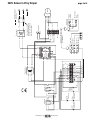
1
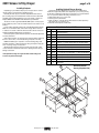
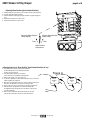
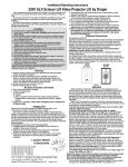
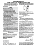
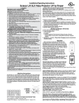
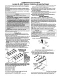
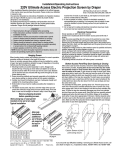
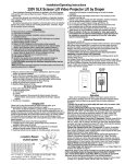
Installation/Operating Instructions
220V SL & SLX Scissor Lift Video Projector Lift by Draper
➂ Fastening methods must be suitable for mounting surface, and securely
anchored so that vibration or abusive pulling on unit will not weaken
installation.
➃ Unit should be level, with weight shared more or less equally by all four
threaded mounting rods.
➄ Bottom of unit must be unobstructed after installation. Sufficient clearance
must be allowed below projector or optional ceiling closure: 4' for Model
SL4, 5' for Model SL5, etc.; 11' for Model SLX11, 12' for Model SLX12, etc.
➅ Do not use unit to support adjacent ceiling, light fixtures, etc.
➆ Do not complete the ceiling below unit until electrical connections have
been completed and unit has been operated successfully.
➇ We recommend that safety cables be attached to the Scissor Lift for added
security (a sound installation practice with overhead equipment).
These Installation/Operating Instructions are available in the official language
of the country where you purchase the product. Please contact your
distributor to request a copy.
Vous pourriez demander les instructions d’installation et d’opération traduises
dans la langue officielle du pays ou vous achetez le produit. Veuillez
demander à votre distributeur.
Die Gebrauchsanweisung für Installation und Konstruktion sind in der
offiziellen Sprache des Landes, indem Sie das Produkt gekauft haben,
vorhanden. Fragen Sie die jeweilige Verkaufs-Abteilung.
Caution:
➀ Read instructions completely before proceeding.
➁ Test lift prior to installation.
➂ Follow instructions carefully. Installation contrary to instructions
invalidates warranty.
➃ Do not obstruct operation of Scissor Lift with fingers or any object.
Serious injury or damage could result.
➄ Scissor Lift is designed to accommodate ceiling suspended equipment.
Equipment should not be allowed to rest on optional ceiling closure
during operation. (Refer to section titled “Installing Projector.”)
➅ Entire bottom of unit must be unobstructed to permit proper operation.
Sufficient clearance must be allowed below projector or optional ceiling
closure: see chart on page 4.
➆ Unit must be installed level (use a carpenter’s level).
➇ Unit operates on 220V, 50 Hz. AC current.
Note: Unit has been thoroughly inspected and tested at factory and found
to be operating properly prior to shipment.
Electrical Connections
Unit operates on 220V AC, 50 Hz. current. Removing the top cover of the
unit and opening the electrical box exposes terminals for field connections.
Unit is shipped with internal wiring complete. Wire to connect unit to power
supply should be furnished by installer. Connections should be made in
accordance with wiring diagram, and wiring should comply with national and
local electrical codes. All operating switches should be “off” before power is
connected.
Scissor Lift should be operated and checked prior to installing projector and/or
optional ceiling closure.
Standard switch shown below comes with 22.86 meters of cable and should
be plugged in to box on front of top pan of lift to control lift.
Planning
UP
OFF
➀ Based on screen location and projector specifications, determine proper
position for projector installation.
➁ Confirm that there is adequate space for installation and operation.
Minimum clearance above ceiling level varies according to Scissor Lift
model, plus height of projector, optional mounting bracket, optional ceiling
closure, and optional plenum rated housing.
➂ Arrange to provide service access to the unit.
As Soon As Scissor Lift Arrives
Operation
➀ Open carton and inspect for damage.
➁ Locate the following parts:
A. The unit itself
B. Controls
C. Any optional equipment: plenum housing, closure panel, ceiling finish kit
or decorative cover (all ship in separate cartons).
➂ Test lift prior to installation.
Hanging Unit
The Scissor Lift may be installed in a variety of ways; recessed above the
ceiling, or suspended below the ceiling. The lift should be supported by four
½" threaded mounting rods. If ceiling recessed, the entire unit (including
the projector) should set approximately 1½" above the finished ceiling in its
“stored” position. The threaded rods should pass through the corner mounting
flanges and be secured by nuts above and below. Use a thread locking
compound such as Loctite® #242 (provided). The unit should then be guy
wired or blocked to prevent swinging.
All installations should observe the following guidelines:
➀ Access from above the unit, with enough clearance to remove the top
cover, should be provided in case service is required. If installing above a
hard ceiling, optional Draper Access Panels are available to allow access to
the unit.
➁ Installer must ensure that all fasteners and supports are of adequate
strength to securely support Scissor Lift and projector.
®
OFF
DOWN
When unit is first operated, be cautious! If unit fails to operate when toggle
switch is flipped “down”, return switch to “off” and recheck electrical
connections before proceeding. Cycle unit down and up several times to
confirm satisfactory operation.
Standard Single Station Control (CE Approved)—One, 12V toggle switch:
moving 3-position toggle switch to “down” position will start lift down. Moving
toggle switch to “up” will start lift up. When lift is in “show” position, travel will
automatically be stopped by factory set limit switches. Whenever switch is
placed in center “off” position, operation will stop. One, 12V key switch will
lower lift from “show” to “service” position.
Video Interface Control (CE Approved)—This optional 12V control device
allows the Scissor Lift switch to control the operation of a Draper motorized
projection screen via a relay.
Multiple Station Control (Not CE Approved)—Optional, moves lift from
“stored” to “show” position only. Each switching station has a 3-button switch
with “up”, “down”, and “off” buttons. Lift starts up or down when appropriate
button is pressed, and may be stopped by pressing “off” button. Factory set
limit switches stop lift automatically when projector is in “show” position.
Key Operated Switch (Not CE Approved)—If ordered, a single station, keyoperated three position (up/off/down) switch is available. Multiple Station Control required for this option. Moves lift from “stored” to “show” positions only.
Infrared or Radio Frequency Remote Control (CE Approved)—If ordered, a
three-button transmitter is provided, with “up”, “down”, and “stop” buttons. Unit
starts up or down when appropriate button is pressed, and may be stopped by
pressing “off” button. Factory set limit switches stop unit automatically when
projector is in “show” position. Only controls "show" and "stored" positions.
Loctite® is a registered trademark of Henkel Corporation.
Copyright © 2008 Draper Inc.
Form ScissorLift_220VInst08
Printed in U.S.A.
If you encounter any difficulties installing or servicing your Scissor Lift, call your
dealer or Draper, Inc. in Spiceland, Indiana, 765-987-7999; or fax 765-987-7142.
220V Scissor Lift by Draper
page 2 of 6
Installing Projector
Installing Optional Plenum Housing
Depending on job conditions and projector, it may be easier to remove
optional ceiling closure panel before installing projector.
Generally, the video projector should be suspended from the bottom
pan according to projector manufacturer’s instructions and recommended
standard ceiling mounting hardware. For projectors 10 kgs or below, use
Draper's SMS Low Profile Mount with Universal Projector Bracket.
The Scissor Lift has a grounded 220V AC, 60Hz power cord for projector
power supply. The power cord is laced down the back scissor and is “hot” at
all times.
Control cables should be laced through our Cable Management System.
Make sure to use flexible cables, and to allow enough cable at each turn
so cables do not stretch or kink. This will ensure that cords do not become
tangled and damaged during Scissor Lift operation.
Unit and projection system should be operated, checked and adjusted as
necessary at this time.
After testing operations, the optional closure panel should be reattached.
Be sure to use Loctite®, or other thread locking compound on the nuts.
NOTE: Immediately upon completion of the surrounding ceiling, units
should be operated to confirm that optional ceiling closure panel stops just
short of touching ceiling in closed position.
Warning: Keep fingers and other objects away from automatic ceiling
closure and scissor mechanisms when unit is operating. Serious injury or
damage could result.
Some plenum housings are longer than wide and mounting hole
locations for plenum will change.
The Plenum Housing is shipped in pieces, and must be assembled by the
installer. The height of the plenum can be adjusted by up to 2" (5 cm) by moving
the trim frame to different mounting holes in side panels. It is recommended that
an access panel be installed in the ceiling to allow future access.
➀ Attach Plenum frame to top of Scissor Lift.
➁ Install top panel to plenum frame.
➂ Attach assembly to overhead structure. Allow clearance between plenum top
and structure for ease of future access.
➃ Install side and end panels, and trim frame.
Parts List for Scissor Lift Plenum
Item Quantity
Part
1
1
Plenum Top Frame
2
2
Plenum End Panel
3
2
Plenum Side Panel
4
1
Plenum Top Panel
5
varies
#10-32 x 3/8" (9.5mm) Hex Head Screw with Zinc Washer
6
varies
#8-32 Zinc Keps Lock Nut
7
varies
½" (8mm)-13 x 3½" (90 mm) Zinc Hex Head Screw
8
varies
½" (8mm)-13 Zinc Hex Grd 2
9
varies
3
10
varies
¼"(6mm)-20 x 1½"(38mm) Zinc Hex Head Screw
11
varies
¼" (6mm) Flat Zinc Washer
12
varies
¼"(6mm)-20 Zinc Nylon Insert Lock Nut
13
1
/16"(5 mm) ID x 5"(127mm) OD x 1/16"(3mm) tk Flat Washer
Trim Frame
4
Scissor Lift Plenum
Housing (Exploded View)
2
3
6 5
13
7 8
1
10 11 12
www.draperinc.com
(765) 987-7999
6
9
220V Scissor Lift by Draper
page 3 of 6
Installing Optional Ceiling Closure Panel—"B", "S", "E", "J"
Optional Ceiling Closure for Scissor Lift
If your Scissor Lift is equipped with a "B" or "E" ceiling closure panel, it can be
used as is, or in conjunction with a piece of existing ceiling tile.
➀ If installing with ceiling tile, you may need to cut tile so its overall dimensions
are the same as (or slightly less than) the closure panel. Place tile into trim
frame. Lay closure panel on top (back side) of ceiling tile, and tighten screws to
hold in place.
➁ Attach provided angle brackets to side of bottom pan of Scissor Lift.
➂ For larger units, attach short angle brackets to ends of long angle brackets.
➃ Attach 5/16" (8mm) threaded rods to angle bracket.
➄ Run unit “up” until bottom pan stops at highest position. Mark position on 5/16"
(8mm) rods even with ceiling and cut to length (remove from pan if convenient).
➅ Run unit “down” until bottom pan stops at “show” position.
➆ Attach closure to lower end of 5/16" (8mm) rods by slipping into four corner slots
and secure with nuts above and below slots.
➇ Run unit “up” again to highest position. Measure distance by which panel
fails to reach required “closed” height for surrounding ceiling.
➈ Run unit “down” then re-adjust mounting of 5/16" (8mm) rods in traveling grid to
raise panel required distance.
➉ Test unit operation to confirm that panel will stop in closed position just
before touching ceiling.
NOTE: Immediately upon completion of the surrounding ceiling, unit should be
operated to confirm that optional ceiling closure panel stops just short of touching
ceiling in closed position.
Installing Optional Ceiling Closure—"G", "U"
Your Scissor Lift can be equipped with an optional ceiling closure system. To install
it:
➀ Remove closure and all mounting hardware from carton.
➁ Optional ceiling closure can be mounted in either of the following styles:
A. If ceiling tile is to be inserted in the closure, this may be done now, or later
when the rest of the ceiling is installed (permitting a better match). Cut tile so
that its overall dimensions are the same as (or slightly less than) the closure
panel. Attach to the closure panel with adhesive.
B. Position one pre-cut aluminum tee along outside edge of panel so arm
extends under and rests on the panel (or tile if tile is being used). Be careful
not to compress the tile. Drill three holes through rib of tee into edge of panel
and pop rivet into place (or use self-tapping screws).
C. Follow same procedure with remaining 3 tees.
NOTE: Since tees comprise part of exposed trim, care should be taken to
ensure accurate fit.
➂ Attach two (2) mounting angles to the corresponding holes in the bottom pan
with the supplied hardware.
➃ Attach other two (2) mounting angles at 90° to previous angles (right to left) in
the corresponding holes with the supplied hardware.
➄ Attach one of four 3/8" (10 mm) threaded rods by passing the rod through one of
the four corner holes, in the angles and secure with nuts top and bottom.
Approximately ½" (13 mm) of rod should extend above angle.
➅ Run unit “up” until bottom pan stops at highest position. Mark position on 3/8" (10
mm) rod that is even with ceiling level and cut rod to length (removing it from
pan if convenient). Cut remaining three rods to same length.
➆ Run unit “down” until bottom pan stops at “show” position. Secure all four 3/8"
(10 mm) rods to traveling pan in same fashion as first one.
➇ Attach closure to lower end of each 3/8" rod using two remaining nuts on each
rod to firmly clamp fixtures on top of panel.
➈ Run unit “up” again to highest position. Measure distance by which panel
fails to reach required “closed” height for surrounding ceiling.
➉ Run unit “down” then readjust mounting of 3/8" rods in traveling grid to raise
panel required distance.
NOTE: Rods should not extend more than 1" above the angles attached to
the pan. Cut extra rod off if necessary.
11 Test unit operation to confirm that panel will stop in closed position just
before touching ceiling.
Bottom Pan of
Scissor Lift
Angles with
Pre-drilled Holes
Threaded Rod
Installer to Drill Holes
Closure Pan
Tee Moulding
(w/Mitred Corners)
Pop Rivets or Screws
Supplied by Others
Optional Acoustical
Tile by Others
E, G, J
Ceiling Finish Kit
Bottom Pan of
Scissor Lift
Angles with
Pre-drilled Holes
Threaded Rod
8-32 Weld Studs
Trim Frame
Installing Optional Ceiling Finish Kit
The Scissor Lift is available with a ceiling finish kit, which consists of the lower
section of the plenum housing (trim frame) and the closure panel.
➀ Install Scissor Lift as previously described in these instructions.
➁ Install trim frame in opening. This can be accomplished by suspending with
wire or mounting directly to ceiling joists (if space permits).
➂ Install projector and attach optional ceiling closure panel to Scissor Lift. See
above for appropriate ceiling closure instructions.
Closure Pan
Tee Moulding
(w/Mitred Corners)
Installer to Drill Holes
Pop Rivets or Screws
Supplied by Others
Optional Acoustical
Tile by Others
www.draperinc.com
(765) 987-7999
220V Scissor Lift by Draper
page 4 of 6
SL Series
Scissor Lift Dimensions
Model
SL4
SL5
SL6
SL7
SL8
SL9
SL10
SLX11
SLX12
SLX13
SLX14
SLX15
SLX16
SLX17
Maximum
Lowering Retracted
Distance Height 1
122 cm
21 cm
152 cm
24 cm
183 cm
26 cm
213 cm
29 cm
244 cm
31 cm
274 cm
33 cm
305 cm
36 cm
335 cm
35 cm
366 cm
40 cm
396 cm
40 cm
427 cm
44 cm
457 cm
44 cm
488 cm
49 cm
518 cm
49 cm
597 mm
528 mm
585 mm
528 mm
15 mm dia.
mounting holes
See chart
(shown slightly
lowered)
Space for
projector's
ceiling
mounting
bracket
Fail-safe inertial
safety belt system
Space for projector
Pair of 5 mm aircraft cables
Optional ceiling
closure panel
51 mm
SLX Series
m
6m
m
68
9m
62
67
75
9m
0m
m
m
1
SMS Low Profile Mount adds 124
mm, including universal projector
bracket, to unit height.
14.3 mm dia.
mounting holes
See chart
(shown slightly lowered)
Fail-safe inertial
safety belt system
Space for projector's
ceiling mounting bracket
Pair of 5 mm aircraft cables
Space for projector
Optional ceiling
closure panel
51 mm
Typical Installation Details
Mounting brackets with
14.3 mm dia. holes
Typical mounting
hardware—12.7 mm
threaded rods
by installer
Scissors, positioned
on left and right
Drive system
enclosure
Stabilizing 3rd
scissor on rear
*For projectors
through 10 kgs
Fail–safe inertial
safety belt
Typical projector
by others
www.draperinc.com
Bottom pan
SMS Low Profile Mount
with Universal Bracket
(765) 987-7999
www.draperinc.com
(765) 987-7999
BE
RD
NC
NO
COM
(-) (+)
Down
Service position
Limit switch
RD
BE
Down
Show position
Limit switch
Down
Key
Limit switch
RD
RD
Up Relay
BE
BE
BK
Up
Limit
Switch
(DPDT)
BE
NC
NO
COM
(-) (+)
RD
BK
BK
Down Relay
BE
YW
BE
BE
RD
BE
BE
RD
BK
BN WH BK GN RD
BE RD RD RD BK BE BK BK
YW
BE
YW
BE BK
BK
12V
Key
Key
BK RD BK
BK
RD
WH
BK
1 2 3 4 5 6 7 8 9 10
3x3
Connection
Board
1 2 3 4 5 6 7 8 9 10
WH
1A
BK
3A
YW
Transformer
10A
BN
GN
BE
BK
BK
RD
RD
Down
(Brown)
Up (Red)
Common
(Yellow)
GN
BK
RD
Dn
Up
BK
WH
Motor
Momentary
Key
Switch
Toggle
Switch
BK
RD
RD not used
GN
BE
YW
BE
GN
GRD
N
L1
Dashed wiring by
electrician
Wall Switch
Capacitor
Fuses and fuse clips
provided by Draper are
located in the electrical
box (also provided).
BLUE
RED
6 Conductor Modular Cable
(75' supplied)
WH
BK
Transformer
220V Scissor Lift by Draper
page 5 of 6
220V Scissor Lift by Draper
page 6 of 6
Adjusting Show Position (Up to Standard Position)
➀ Find the empty slot in the bottom of the top pan of lift (the only empty slot).
➁ Use the open-end wrench (provided)
➂ Find the threaded coupling (long nut) just inside the top pan (through the
slot).
➃ Push wrench toward rear of unit to lower.
➄ Pull wrench toward front of unit to raise.
Decrease Show Position
(Stops Higher)
Front
Front of Unit
Increase Show Position
(Stops Lower)
Rear
Show Position
Adjustments
Adjusting Scissor Lift “Show Position” Past Standard Position (46 cm)
➀ If the desired show position is beyond the standard
position (46 cm) but not more than half the service
position, proceed to step #7.
➁ If the desired show position is over half the
service position, proceed with the following steps.
➂ Remove the top pan cover of the scissor lift.
➃ Locate micro switches # 1 and #2 that are wired in series on the micro
switch assembly (see figure #1).
➄ Disconnect the yellow wire from m/s #1 from the red wire from m/s #2.
Disconnect the black wire from m/s #1 from the green wire.
➅ Connect the green wire to the red wire from m/s #2 (see figure #2).
➆ At this point you can adjust the micro switch assembly, with
the supplied wrench, through the slot in the bottom of the top pan
(see above drawing).
➇ After you have reached the desired show position, raise and
lower the unit several times in order to verify show position.
www.draperinc.com
Figure A
Micro
Switch
#2
COM
(765) 987-7999
NC
Micro
Switch
#1
COM
NC