1
Model 5220
Stereo
~R
Cassette Deck
MARANTZ CO., INC . 20525 NORDHOFF STREET, CHATSWORTH, CALIFORNIA 91311
A WHOLLY-OWNED SUBSIDIARY OF SUPERSCOPE INC., CHATSWORTH, CALIFORNIA 91311
E
o
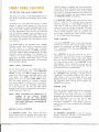
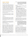
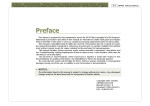
To obtain maximum performance and enjoyment
from t he Model 5220 Ste reo Cassette Deck,
please study these instructi ons carefully. Install
ing and ope rating the Mode l 5220 is not com pi i
cated, but the flexib il ity p rov ided by its nume
rous operating features merits your becoming
fam il iar with its controls and connections. Our
recommended procedures will assure you of
securing the superb performance for which the
Model 5220 was designed.
For convenience, this manual is divided into three
parts. The first part covers installation. The
second part outlines a simplified operating pro
cedure. The third part provides a more detailed
description of the features of the Model 5220,
and explains some of the finer points of recording
techniques. Technical specifications are also in
cluded in this part.
For quick identification of the many controls,
connection facilities, and adjustments on the
Model 5220 all references to them in this manual
are printed in BOLDFACE type.
AC Line Operation
WARNING : TO PREVENT FIRE OR SHOCK HAZARD, 00
NOT EXPOSE THIS APPLIANCE TO RAIN OR MOISTURE.
FT
A
It is advisable to reta in all original packing
material to p revent d amage should you wish to
transport or ship the Model 5220 (refe r to page
16 for repacking and shipping instructions). Be
careful t hat you do not inadvertently throwaway
or lose the parts packed with the unit.
Please inspect your Model 5220 Stereo Cassette
Deck carefully for any signs of shipping damage.
Our very strict qu ality control and profess ional
pride ensure that each Model 5220 left the
factory in perfect condition. If the unit is
damaged or fails to operate, immediately notify
your dealer. If the unit was shipped to you
directly, notify the transportation company with
out delay. Only you, the consignee, may institute
a claim against the carrier for shipping damage.
Save the carton and all packing material as
evidence of damage for their inspection. Should
assistance be required, the Marantz Company will
cooperate fully in assisting your cla im.
Please fill out and m ail the Warranty Registration
Card within ten days of purchase. The card will
rema in on fi le at the Marantz Company for the
durat ion of the w arranty per iod. We also st rongly
advise that you ret ain your sales receipt to
prov ide proof of purchase in the event that
Warranty service is sought.
I
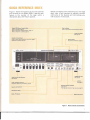
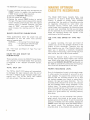
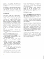
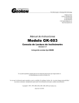
Figure 1 shows the lo cation of the main co nt rols
and switches on the Model 5220. Listed by each
feature is the number of the page where a
description about the fe ature appears.
Model 5220 Stereo Cass ette Deck
How to connect, p age 5.
How to use with a Dol b y Sy stem , p age 12 .
Ho w to install in a cab ine t, pa ge 3 .
Before proceeding with connect ing your new tape
deck, take a f ew moments to acqu aint yourself
with some of the features and term inology you
will encounter in this book.
Peak Indicator
How to se t p roper record ing levels, page 8.
Large VU Met ers
See pa ge 8 .
Cassette Compartment
How to ma ke rea lly excellen t reco rd ings, p age 9 .
Clea n in g the h ead s, p age 10 .
Pow er Switch
AC po wer co n nect io n, page 5.
p u _ _r
~
Tape Counter with Memory
See pa ge 8 .
Tape T rans por t Controls
S im p lified Opera ting Proc edure, pa ge 6 .
Input Level Controls
ph..,.....
Headphone Jack
See pa ge 8 .
Limiter
See p age 8.
Bias/Equalization Selector
See page 9 .
Th e typ e an d br and of ta pe y ou use , pa ge 9 .
Microphone Jacks
Dolby FM Switch
Dolby NR Switch
Figure 1. Main Controls and Switches
2
liON F
MECHANICAL INSTALLATION
The Model 5220 Stereo Cassette Dec k can be
installed in two basic ways : I n a beautiful walnut
veneer cabinet for placement on a table or shelf,
or mounted i n your own cabinetry or custom
installation.
MARANTZ WALNUT CABINET
An attractive walnut veneer cabinet, Model
WC-15T, may be obtained from your Marantz
dealer. The case provides for proper ventilation,
and can be placed on furniture, or on a bookshelf.
Complete instructions for installation are pro
vided with the WC-15T.
CUSTOM INST ALLATIOI\I
When planning a custom installation, allow ade
quate spacing between the Model 5220, cabinet
surfaces, and other componets for adequate venti
lation.
To install the Model 5220 Stereo Cassette Deck in
a custom cabinet, cut an opening 16-7/8 inches
wide by 5-1/8 inches high. Since the front panel
of the Model 5220 is larger than the cutout, it
will neatly hide the edges of the cut. Remove the
plastic feet from the bottom of the unit and slide
it through the opening. To support the weight of
the Model 5220, adequate bracing across the rear
of the cabinet must be located to provide contact
with the rear of the unit.
3
_ __
_
H3"/383t1 03t131S
o
an
"dll\lV 03H31S
@88888 8
@ 0
°
@
o
0
-_
...-------....:~
.___.r_
~
r _
_
-
_
~
_
~
_
,,_
~
-....-
~
..
~-------~ ~
_..--.
-.....-""---'~
....--...=-_
- ~ -.~
-----,. ~
------- ~
....::::::,::::--... _ ..,..~~
.,.... ......
~-~~
--~
Ina 3dVI
~
NI 3dVI
1@ @H 1@ @H
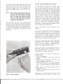
CONNECTING
THE MODEL 5220
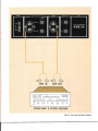
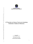
REAR PANEL SIGNAL COI\INECTIONS
Figure 2 shows th e loc ation of th e input and
output jack s on the rear panel. Thes e j acks are for
" permanent " connections. Front panel jacks and
their use will be discussed later.
All connections to the rear panel should be m ade
with the power to the ent i re system tu rned off.
The rear panel signal connect ions should be made
with shielded audio cables. To avoid confusion,
connect one cable at a time between the 5220
and the oth er components of your system. This is
the safest w ay to avo id cross-connect i ng channels
or confusing signal source outputs with input s.
When connecting audio cables insert the con
nectors completely into the j acks. Loose con
nections may cause hum and noi se.
LINE INPUTS
These jac ks will accept signals from any line level
sou rce. They are also the inputs for the DOLBY
FM circuitry in the Model 5220. Therefore, th ese
jacks should be connected to the set of t ape
output jacks on your receiver, which will supply
signals from FM and other audio sources. If you
own an aud io system comprised of separate
components, conn ect the LINE IN jacks of th e
Model 5220 to th e t ape output j acks of your
preamplifier.
LINE OUTPUTS AND OUTPUT LEVEL
CONTROLS
Connect th e OUTPUT to the t ape monitor input
jacks of your receiv er.
The LEVEL controls located next to the output
jacks determine the volume output of each
channel. They operate the same as a volume
control, and can be turned with a screwdriver. The
purpose of these adj ust m ents is to m at ch the
output level of the Model 5220 to the input
sensitivity of the tape monitor circuits in your
receiver. When the LEVEL controls are properly
adjusted, th e volume through your speak ers wi ll
remain constant as the tape monitor is sw it ched
in and out. Of course, you can't m ake th ese
adjustments until the system is set up, so for the
present time, the LEVEL controls should be set
ap p rox i mate ly on e qu arter turn above the mini
mum volume setting.
5
AC POWER SOURCE CONNECTION
With the POWER switch set to the OF F (out)
position, plug the AC line cord into an AC outlet
providing the proper voltage.
CAUTION: DO NOT PLUG THE MODEL 5220
INTO A DC OUTLET, AS SERIOUS
DAMAGE WILL OCCUR.
I f you r receiver has a switched AC outlet on its
rear pan el, you may f ind it convenient to plug the
Model 5220 into that outlet.
Now that you have connect ed your Model 5220
to you r receiver and external t ape recorder, you
are doubtlessly eager to try it out. So, the
following section will outline a simplified operat
ing proc edure to follow so you can begin record
ing and listening to your new St ereo Cassette
Deck immediately. After becoming famili ar with
the Stereo Cassette Deck, you may tak e full
advantage of its many featu res and operating
versati Iitv.
I
o
INSTRUCTIO
Fi rst , set the control s and switches on t he Model
5220 as foll ows:
PO WE R Switch
TAPE TRAN SPO RT Controls
DOLBY NR Switch
DOLBY FM-OFF Switch
DOLBY FM-OI\I Swit ch
BIAS/EQ SELECTOR Switches
LIMITER
ALL LEVEL Controis
OFF (out)
STOPPE D
OFF (out)
(in)
(out)
Depress button that
matches kind of tape
used.
OFF (out)
Minim um (to left)
Af ter setting the controls and SWitches, record on
a b lan k cassette as fol lo ws:
1. De pr ess th e POWER swi tch . Th e m et er s will
illuminate, indicating t he uni t's power is on.
If they don 't, check to make sure the power
cord is plugged in. Turn on the sou rce
eq u ipm ent (receiver, t urntable, etc .l
2. Befo re inserting th e cassette, take up the slack
of t he ta pe t o preve nt it f rom beco m ing
en tangled ar ound the capstan . T w ist the tape
hub inside t he cassette with your fingernai l or
with a pencil . (See Fig ure 4 .)
3. De p ress t he EJECT b utton fu lly t o open the
ca sset te compartme nt and raise th e cassette
holder.
----~--
--- -
---
---,
ejee::1
ree::
re~
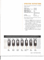
Eject
Button
Record
Button
Rewind
Button
play
ff
slop
pause
Stop
Button
Pause
Button
I
Play
Button
Fast Forward
Button
Figure 3. Tape Transport Controls
6
4. Insert the cassette with the desired side for
recording up. Close the lid.
I\IOTE: The cassette can only be inserted if the
cassette holder is up.
5 . Play the audio signal source (phono, tuner,
etc.) with the tape monitor switch on the
receiver in the "source" position.
6. Press the RESET button on the tape COUN
TER to reference the beginning of the re
cording.
7. Place the Model 5220 in the record mode:
Depress the record (REC) and PLAY buttons
simultaneously. The REC light between the
VU meters will illuminate.
NOTE: The smoothest way to engage the record
mode is to depress the R EC button first.
Then, while holding it down, depress the
PLAY button.
8. Slide the MASTER LEVEL Control to its
maximum setting (to the right). All other
controls should be set at minimum.
9 . Gradually increase the left and right LINE
level controls while watching the VU meters.
Adjust the level controls so that the loudest
passages of the program deflect the pointers
of the meters as fully as possible w ith
minimum triggering of the PEAK level in
dicator (light emitting diode).
10. Set the tape monitor switch on the receiver to
the "tape" position .
NOTE: If the volume level changes when the
tape monitor is switched in, adjust the
OUTPUT LEVEL controls on the rear
panel of the 5220. The volume level
should remain constant as the tape
monitor is switched in and out.
11. When finished recording, reduce the MASTER
LEVEL control to minimum and press the
STOP button.
12 . Rewind the tape by depressing the rewind
(REW) button. Stop the tape when the
COUNTER registers zero, or use the MEMO
RY feature (see page 8).
13. Play back the tape by pressing the PLAY
button.
The Model 5220 is now playing back the tape you
just recorded. The following sections will explain
the front panel features and some methods of
adding more sophistication to your recording
technique.
7
CAUTION: Do not attempt to manually lift the
push buttons when they are in the
depressed position. The push buttons
are mechanically locked into posi
tion and can be released only by
depressing the STOP pushbutton.
The PAUSE pushbutton can only be
released by pressing it a second time.
I
A
E
VU METERS AND PEAK INDICATORS
Two large VU meters in the M odel 5220 mon itor
the relat ive recording and playback level of each
channel.
Al l meters are "time sensit ive" devices . I n oth er
words, it takes a short amount of time for the
meter t o respond to a quickly appl ied signal. Even
though the meter needl e and oth er moving par ts
are very l ight w eight , they still have some inertia
and are relatively sluggish w hen co mp ared to the
instanta neo us natu re of audi o peak s. The me te rs,
th en, indi cate an average value reading w ith whi ch
to mon itor the average level and ba lance of the
two channels.
T he Mod el 5220 is also equip ped w ith a PEAK
indicator wh ich , when used in conjuncti on w ith
the V U meters, is a valu abl e aid to proper
recording level adj ust m ent. T he PEAK ind icat o r,
unlike th e meters, reacts instan taneousl y to audio
t ransients du ri ng reco rd i ng. Th e indicator illu
mi nates if an aud io transient st ro ng eno ugh t o
cause tape sat urat ion (d ist orti on ) occurs . I f the
PEAK ind icato r f lashes repeat edl y , t he recordi ng
level shou ld be reduced .
INPUT LEVEL CONTROLS
On the front panel are four independent slide
type input level cont rols and a stereo MASTER
LEVEL cont rol. T he MIC controls receive thei r
in puts f rom the left and right M IC j acks on th e
front panel. T he LINE controls receive their
signal s from t he rear pane l LINE INPU T jacks.
Th e fou r inp ut co ntro ls, or " sliders," combine
the ir audio signals in a stereo mi x in t he propor
ti ons chosen by you , the recordist. They assign
th e aud io inputs t o th e left and ri ght stereo
outp uts of the mi xe r as indicated by the letters L
and R beside each slider slot.
NOTE: When microphone are selected for re
cording, do
not monitor through
speakers, as th is w ill cau se howl ing
(acoustic feedback) which could damage
your aud io equipment. Use headphones
for mon itoring.
ch annels w it hout ch anging th e input slid er pos i
t ions and w it hou t affec ti ng thei r prop o rt ionate
audio levels. If, for instan ce, the four in put levels
are mi xed in the exact proportions you want, but
the VU meters regist er too high a readi ng, reduce
t he MASTER LEVE L accord ingly .
T he MASTER LEVEL slid er can be used to "fade
out" or "fade in" . For ex ample, wh en maki ng a
casset t e record ing of a phonograph reco rd, yo u
may wish to fade out the mu sic gradually jus t
bef o re th e end of th e tape is reach ed. Thi s way ,
y ou w il l avo id th e abrupt cut-o ff of sound tha t
occu rs during playback wh en the cassette runs
out o f t ape. L ikew ise, the mus ic cou ld be " faded
in" at t he beginn ing of the cassette.
PEAK LIMITER
The peak LIMITER , whe n in use, automatically
red uces the reco rd level during sudden vo lu m e
surges. By preventing th e peak record ing level
f rom exc eeding 0 VU, the peak LI MI TER mi ni
m izes di stortion .
T he LIMITER is not the same as an A.L. C.
(A uto mat ic Level Con trol ) ci rcuit ; it is designed
rather as a safeguard against high input signals
that y ou had not anticipated when you adj usted
the record levels in iti all y. Th e LIMITER is also
advan tageous w hen record ing sou rces such as
radio pr ogram s o r live m usic whose peak vol um e
levels are some t imes unpredicta b le.
If t he recording levels we re set m uch too high and
the LIM ITER were activated, it would t end to
" co m press" th e dyn am ic range of th e m usic. In
other words, not o n ly the peaks, but all loud
passages w ou ld be reduced in vo lum e. Th eref o re,
th e recordi ng levels sho uld be set before t he
LIM ITER is t urn ed on .
PHONES JACK
Th is jack accept s headphon es ut ili zing a standard
three condu ctor phon e p lug. It is internally
con nected to t he output circuitry to pr ov id e
adequa te sou nd level with popu lar low impedance
stereo headphon es. Two or more set s of head
phon es may be used wi t h the aid of "Y "
conn ectors (avai lab le at yo ur d ealer). How ever,
ou tput level will drop as addi ti onal headphones
are added.
MASTER LEVEL CON TROL
MEMORY COUN TER
Th e MASTER LEVEL sl id er adju st s th e t otal
stereo output level. It s purp ose is t o control the
aud io level of t he entire m ixture of th e four in pu t
T he MEMORY COUNTER is used for precise
program relocation, whet her at th e beginnin g of
t he side or f ar int o th e record ed t ape.
8
The MEMORY feature operates as follows :
1. Locate a desired starting point and depress the
RESET button to register this starting point.
("000" shown on the Tape Counter).
2. Depress the MEMORY 01\1 button.
3. Play (or record) the tape.
4. Depress the rewind (REW) button to rewind
the tape. The tape motion stops and the rewind
button releases automatically when the original
starting point is reached. Actually, the tape
stops at "999", one count before "000" to
avoid missing the starting point of the pro
gram.
BIAS/EO SELECTOR PUSHSWITCHES
These pushswitches select the proper bias and
equalization to suit the three most common
types of cassette tape:
NORMAL
for normal Ferric Oxide tape
Cr0 2
for Chromium Dioxide tape
Fe-Cr
for Ferri-Chrome tape
See "The Type and Brand of Tape You Use,"
on this page.
DOLBY FM AND DOLBY NR
PUSHSWITCHES
These switches control the DO LBY Noise Reduc
tion circuitry in the Model 5220. Their operation
is explained in the "DOLBY SYSTEM" section
Page 12.
t
TOTAL SHUT OFF
The TOTAL SH UT OF F feature will automatical
ly disengage the tape transport when the end of
the .t ap e is reached in any transport mode (play,
rewind, etc.). The TOTAL SHUT OFF feature
will also activate if the tape should jam.
The Model 5220 Stereo Cassette Deck, aug
mented by its built-in Dolby Noise Reduction
System, is capable of making really excellent
recordings. But the quality of recording can also
be negatively influenced by some other very
important factors. Inferior tape, poorly main
tained heads, and improperly set recording levels
can spoil your recordings. So that you can realize
the full potential of your investment in the Model
5220, the following section will explain a few
techniques of skillful recording.
THE TYPE AND BRAND OF TAPE YOU
USE
In cassette recording, the type and brand of
cassette you use has the greatest influence on the
quality of your recordings. Therefore, buy the
best cassettes you can. Your Marantz dealer will
assist you in selecting a nationally recognized
name brand of low-noise, clean-running tape. For
best results, use a 60 or 90 minute cassette.
Chrom ium Dioxide (Cr0 2) and Ferri-Chrome
(Fe-Cr) tapes provide better fidelity than normal
tape. When using these kinds of tape, depress the
appropriate BIAS/EO SELECTOR pushswitch on
the 5220 to provide the correct bias and equaliza
tion to suit the characteristics of the tape .
PROPER RECORDING LEVEL
One of the beauties of music is its dynam ic range,
in other words, the contrast of very soft to very
loud passages. To capture this contrast on tape
requires that the recording levels be set so that
the loudest passages you intend to record don't
saturate the tape and cause distortion. Yet, the
recording levels shouldn't be set too low, because
the soft passages would simply disappear in the
residual noise. The proper technique is to antici
pate the loudest section of the music you want to
record and set the recording levels using the VU
meters as a guide before any recording actually
takes place.
If, for example, you are recording from a phono
graph record, you should at the outset find the
loudest section of the record. To set the recording
levels on the 5220, insert the cassette, depress the
PAUSE button and then place the Model 5220 in
the record mode. This technique allows the
recording level to be checked and adjusted with
9
I
out actually recording anything on the tape. Once
the levels are set for the loudest portion of the
music, leave them where they are. Start the
phonograph record over at the beginn ing and
release th e PAUSE button to commence record
ing.
NOTE: Most cassette manufacturers splice a few
inches of clear leader tape to the begin
ning and end of the magnetic recording
tape. The leader tape cannot be record
ed, and it usually takes about six seconds
to pass by the heads when the tape is
played from the beginning.
When taking up the slack in the cassette before
inserting it for recording, advance the tape so that
the spliced area of the tape is ready to pass the
recording head (see Figure 4). By knowing exact
ly where the recordable tape begins, you can
assured that the beginning of the program will be
recorded.
CLEAN AND DEMAGNETIZED HEADS
The RECORD/PLAYBACK and ERASE heads
are the most important parts of the stereo
cassette d eck. After tape ru bs agai nst the heads
during record and playback, brown oxide deposits
from th e tape accumulate on the heads, guides,
and pinch roll er. Even the best cassette tapes will
shed some particles of oxide. The accumulation
of this oxide will cause loss of high frequency
response, loss of sound volume, intermittent
sound dropout and unsatisfactory results when
recording or erasing tape. If your Model 5220
exhibits any of the preceding symptoms, immedi
ately cl ean the heads. If the oxide is allowed to
build up, it may cause the heads to wear out
prematurely, causing permanent damage. There
fore, the heads must be kept clean.
Now, a word ab o u t routine preventative rnarn
ten ance:
Don't put off cl e aning th e heads simply because
th e deck is performing well . The experienced
au d io p hi le gives the tape path a thorough cleaning
at the beginning of every usage as a matter of
habit. Thi s is a n exce lle nt practice for ass ur ing
cleanliness and the best possible recording con
ditions, a nd it only requires a minute to do.
To clean the t ape path , use cotton swabs and
denatured alcoho l (available at any pharmacy).
Please note that common "rubbing alcohol"
sho u ld not be used because it has a high water
content. Use " D ENAT U R E D" alcohol.
Dip the cotton swab in the alcohol and clean the
tape heads, capstan, guides, pinch roller - every
where the tape touches - until no more oxide can
be picked up on a fresh cotton swab.
To gain acc ess to th e heads for cleaning and
demagnetiz ation,
1. Turn off the pow er .
2. Depress the EJECT button and remove the
c assette .
3. Rea ch inside th e cassette compartment and
push the c assette holder down.
4. Push the PLAY button. The heads and pinch
roller w ill protrude into the cassette compart
ment. The head surfaces may now be inspect
ed .
5. After cleaning and demagnetizing, press the
STOP button.
6. Depress the EJECT button fully to life the
cassette hold er.
Figure 4. Cassette Preparation
Obviously , the heads and pinch roller of the
Model 5220 are more difficult to inspect, clean,
10
and demagnetize than those of a toploading
cassette machine, because access to the rear-facing
heads must be made through the front-facing
opening. Therefore, you may find it more con
venient to obtain a few special tools to aid
inspection and cleaning.
On your trip to the pharmacy to buy alcohol and
cotton swabs, also buy an inspection mirror (the
kind the dentists use) and an inexpensive
hemostat. The mirror can be used for inspecting
the head surfaces and the rubber pinch roller.
The pinch roller in the cassette mechanism
provides a simple, visual indication of when to
clean the heads. If you can see a stripe of brown
oxide around the perimeter of the pinch roller, it
is time to clean the entire tape path .
The hemostat can be used to hold the cotton
swab while cleaning. If the swab is made of wood,
you may wish to break it in half to provide more
room.
Tape heads and guides also become magnetized
after a period of use. When this occurs they cause
excessive noise and can even partially erase the
tape. The tape heads and guides should be
demagnetized periodically (about every nine
hours of playing time) with a demagnetizer.
The demagnetizer should be of the same design as
those used with 8-track tape cartridge players
that is, the type with a long, slender demagnetiz
ing element bent at an angle near the end.
I nstructions are enclosed with the demagnetizer.
CAUTION: BEFORE USING THE DEIVIAGNE
TIZER, TURN OFF THE POWER
TO THE MODEL 5220.
11
BASIC DOLBY PROCESS
i'
The Dolby system increases the level of low
volume mid- and high- frequency signals during
recording and reduces the level of these signals by
an identical amount during playback. As a result,
the playback signal is identical to the original
source signal, but the level of background noise
generated by the tape recorder is greatly reduced.
A Dolbyized FM broadcast is subjected to the
first phase of the noise reduction process before
being transm itted. When these signals pass
through the Dolby playback circuitry, the mid
and high frequency noise is greatly reduced.
'.
,~
The Dolby Noise Reduction System in the Model
5220 can be used for recording, or for playing
back Dolbyized cassettes.
The following section will explain how to operate
the Dolby Noise Reduction System in the 5220
to process cassettes, FM broadcasts, and external
sources.
CASSETTES
The Dolby Noise Reduction circuit in the Model
5220 is designed for maximum convenience when
recording or playing back a cassette. The calibra
tion levels have been internally preset at the
factory, so the only adjustment to make is that
for recording level.
The procedure for Dolby recording and playback
is identical to that for non-Dolby except that the
DO LBY N R ON pushswitch is depressed after the
recording levels are set.
DOLBY FM BROADCASTS
Dolbyized FM broadcasts contain Dolbyized
audio information to which a special pre-emphasis
applied for the purpose of improving the noise
reduction process. The pre-emphasis time constant
(25jJS) is different from the used with non
Dolbyized broadcasts. To properly recover the
original program material, a complementary time
constant at the receiver is required. A 25 micro
second FM de-emphasis circuit is built into the
Marantz Model 112, 125, and 150 stereo F M
tuners and should be activated when recording or
. listening to Dolby FM broadcasts through your
Model 5220. If your present tuner does not have
such a circuit, set the FM DE-EMPHASIS switch
on the rear panel of the Model 5220 to 25jJS to
activate the corrective network.
I\IOTE: If you are using the de-emphasis circuit
built into the tuner, leave the FM DE
EMPHASIS switch on the Model 5220 at
"F LAT". Do not use both de-emphasis
circuits simultaneously.
To listen to a Dolbyized FM broadcast, proceed
as follows:
1. The tuner or receiver should be connected to
the LINE INPUT jacks.
2. Apply the proper de-emphasis as outlined
above.
3. Depress the DOLBY NR ON pushswitch.
4. Depress the DOLBY FM-ON pushswitch.
5. The Dolby FM calibration levels have been
pre-adjusted at the factory and should not
normally need to be readjusted when used
with the Marantz tuners and receivers equipped
with "DOLBY FM" pushswitches. However,
when used with receivers or tuners not so
equipped, FM calibration will be required. For
this purpose, PLAY/FM CAL controls are
provided on the rear panel. The controls should
be adjusted so that the Dolby reference tone
transmitted by the FM station at the beginning
of a Dolby broadcast registers DO on the VU
meters. Once the levels are set, they do not
need to be readjusted unless a different tuner
or receiver is connected.
The decoded Dolby FM program can be monitord
through the amplifier system. If you are recording
a cassette at the same time, the cassette will be
Dolby encoded to obtain the maximum effect
from the noise reduction process.
NOTE: When the DOLBY FIVI-ON push switch is
depressed, the record input level controls
(the sliders) are bypassed. The recording
level is determined by the PLAY / FM
CA L controls. When the controls are set
properly usi ng the broadcast reference
tone, the levels will be correct for Dolby
recording.
EXTERNAL TAPE RECORDER
The Dolby System in the Model 5220 can be used
as a Dolby decoder for an external tape deck not
equipped with its own Dolby circuits in the same
manner as a decoder for Dolby FM broadcasts.
Because of the dissimilar playback level character
istics of various tape recorders, PLAY /FM CAL
controls are provided on the Model 5220. The
PLAY/FM CAL controls determine the input
sensitivity of the Dolby circuit when playing back
a Dolbyized program from the external unit.
The external tape recorder should be connected
12
di rectly to the rear panel L11\1 E I NPUT. The
outputs of the Model 5220 rema in connected to
the tape monitoring facilities on the preampl ifier
or receiver.
It is necessary to adjust the output level controls
of the external tape deck and the rear panel
PLAY /FM CAL controls on the Model 5220
when using the Dolby System . The following
section will outline calibration, recordi ng and
playback procedures.
a Dolby FM broad cast. Again, the cassette you
record will be Dolby-encoded to obtain the
maximum effect from the noise reduction pro
cess, and no adjustment of the input level
controls is necessary.
If you have purchased a Dolby Calibration
cassette, you may play the cassette on your
Marantz deck to confirm the playback reference
level . The meters should register within 1 dB of
the "DO" mark.
MULTIPLEX FILTER
CALIBRATION
If you haven't already done so, obtain a reel-to
reel Dolby System Calibration Tape from your
Marantz dealer. The calibration tape is also
available in cassette format, if your external
record er is another cassette deck. The tape is
prerecorded with a 400 Hz tone at the specified
Dolby level and is used for setting the output
levels of you r external tape deck and the PLAY /
FM CAL levels on your Model 5220. Use and
store the calibration tape carefully to avoid
accidental erasure. For examp le, do not store the
calibration tape on top of your power amplifier,
because th e magnetic fields produced by the
transformer in the amplifier could partially erase
the tape. (The same holds true for any cassette
tape!)
When you have obtained a cal ibration tape ,
proceed as follows :
1. Set the tape monitor switch on your receiver to
"T APE".
2. Depress th e DOLBY NR ON pushswitch.
3. Depress th e DOLBY FM-ON push switch.
4. If you are using the 251lSec de-emphasis circuit
in the Model 5220, switch it to FLAT.
5. Load the Dolby Calibration Tape on your
external recorder and play it.
6. Set the monitor switch (es) on the ex t ernal
recorder to "TAPE" and adjust the output
level controls so that the VU meters register
7. With the tape still playing, adjust the PLAY/
FIVI CAL controls on the rear pane l of the
Model 5220 so that its VU meters register DO.
8. When the levels are set, rewind the remove the
calibration tape .
NOTE: The Model 5220 may be left in the stop
position when using the Dolby circuits
to decode an external source.
The decoded program from the external tape
recorder can be monitored through the amplifier
system. To make a cassette copy of the program,
insert a cassette and record in the same manner as
13
The rear panel MPX FI L TE R switch activates a
high filter which is specially designed to block the
high frequency multiplex pilot and subcarrier
signals which are present in stereo FM broadcasts.
Although these pilot and subcarrier signals are
outside the human hearing range, they can inhibit
the action of the noise reduction circuit when
making Dolby encoded recordings of standard FM
stereo broadcasts.
Normally, it is the job of the tuner or receiver to
filter out these undesired signals. Most high
quality tuner sections already provide sufficient
(40 dB) pilot and subcarrier rejection. I n fact,
with all Marantz tuners and receivers, use of the
MPX FI LTER is unnecessary. However, to ensure
correct operation of the noise reduction circuitry
when used with other brands of tuners that may
not have sufficient pilot and subcarrier rejection,
the MPX FILTER is provided.
If you are using a non-Marantz tuner, and if the
Dolby circuit seems to have no effect when
recording from FM stereo, then activate the MPX
FI L TER. The filter will then block the high
frequency interference and allow the Dolby cir
cu itry to operate as designed.
,
r
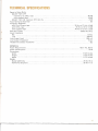
TECHNICAL SPECIFICA
Signal to Noise Rati o
DOLB Y NR OFF
wi t h F E-Cr o r CR0 2 t ape
w ith sta ndar d ta pe
DOL BY NR ON improves SiN rat io by
T otal Harm oni c Dist or t ion
Fr equ ency Respon se
w ith Ferr i-Chrome t ape
w it h C R0 2 t ape . . . . . . . . . . . . . . . . . . . . . . . . . . . . . . . . . . . . . . . . . . . . . . . . . . .
w it h standard t ape
,
"
Wow and Flutte r
Input Im pedance
Mi c
L ine
.....
Li ne Output Level
L ine Output Impedance
Headph o nes Outp ut Im pedance
GENER AL
Po wer Req uir em ents
Powe r Co nsumptio n
Di m ension s:
Wi d th
He ight
Depth
Weight :
Mode l 52 20 Only
Packed f o r Shi p m ent
50 dB
48 dB
8 dB
3%
35 Hz to 17 kH z ±3 d B
35 Hz to 15 Hz ±3 dB
45 Hz to 13 kH z ±3 dB
' " 0.0 8% W. R.M .S.
10 kst,
100 kst,
. . . . . . . . . .. 900 m V
6 kst,
8st,
120 V A C, 60 Hz
25 W
17-3/ 8 inches
5-318 in ch es
11 -1 12 inc hes
20 Ibs 10 oz
26 Ibs 11 oz
14
MAINTE ANC
CLEAI\IING
The satin gold anodized finish of the aluminum
front panel and the smoked plexiglas window will
last indefinitely with proper care and cleaning.
NEVER use scouring pads, steel wool, scouring
powders, or harsh chem ical agents, such as lye
solution. These will mar the finish. Clean with a
soft lint-free cloth or cotton swab slightly
dampened with a mild solution of detergent and
water.
REPAIRS
Only the most competent and qualified service
technicians should be allowed to service the
Model 5220. The Marantz Company and its
factory-trained warranty station personnel have
the knowledge and special equipment needed for
repair and calibration of this precision instru
ment.
In the event of difficulty, refer to the list of
Authorized Marantz Service Stations packed with
the Model 5220 or write directly to the location
listed below for the name and address of the
Marantz authorized service station nearest your
home or business. Please include the model and
serial number of your unit together with a full
description of what you feel is abnormal in its
behavior.
IN CASE OF DIFFICULTY
If your set is not operating properly, check the
following points:
1. Tape not running.
• Improper connection of power cord.
• POWER switch in OF F position.
• Defective cassette.
2. Record button will not go down.
• No cassette inserted.
• No erasure prevention tab on cassette.
3. Tape ru ns but no sou nd.
• Tape not recorded.
• Improper or
incorrect connection
of
amplifier or speaker.
• Volume control of amplifier IS In MIN
position.
• Ampl ifier select switch not in TAPE pos
ition.
4. Level meter is dead during recording (no
recording) .
• DOLBY FM-ON switch is depressed.
5. Distortion in sound.
• Record level is too high.
6. Wow in sound.
• Tape head is dirty.
• Pinch-roller (capstan) is dirty.
• Defective tape (warped or stretched tape).
• Tape is not wound neatly or it is wound too
tight.
• Defective cassette with excessive tape drag.
7. Excessive noise.
• Tape head requires demagnetization.
• Defective tape.
8. Hum in sound.
• Improper connection of shielded cable.
• AC magnetic field from power transformer
of external equipment is in close proximity
to tape head.
15
Marantz Company, Inc.
Technical Service Dept.
P.O. Box 577
Chatsworth, CA 91311
U.S.A.
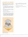
Should it become necessary to repack your Model
5220 for sh ipment to the factory, to an autho
rized service station, or elsewhere, please observe
the following precautions:
d. Ship via a reputable carrier (do not use Parcel
Post) and obtain a shipping receipt from the
carrier.
e. Insure the unit for its full value.
a. Do not ship your unit to the factory without
an Authorized Return Label, which the
Marantz Company will supply if the descrip
tion of difficulties appears to warrant factory
service.
f. Be sure to include your return address on the
shipping label.
b. Do not ship the unit installed in its accessory
walnut cabinet; remove the unit from the
cabinet before packing.
c. Pack the unit carefully, using the original
material as shown in Figure 5.
PLEASE NOTE that if you have discarded,
lost, or damaged the packing material, new
packing material may be obtained by writing to
the Marantz Technical Services Department.
The carton, its fillers, and packing instructions
will be returned to you at a nominal charge.
Figure 5. Packing Instructions
"16
NOTES
The Sound of Marantz
is the compelling warmth of a Stradivarius
It
IS
a dancing flute, a haughty bassoon
and the plaintive call of
lone French horn.
Th Sound of Marantz is the sound of beauty,
and Marantz equipment is designed to bring you
the subtle joy of its delight.
Wonderful adventures in sound await you
when you discover that the Sound of Marantz
is the sound of music at its very best.
Noi se reduct ion circ uit under license fr om Dolb y Laboratories. In c.
" DOL BY " and the Do uble-D symbol are tr ademar ks of Do lb y Labor at or ies. Inc.
Printed In Jap a n
34 4885 101·0