1
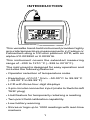
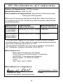
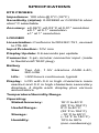
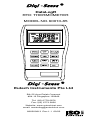
Digi -Sense ®
DataLogR
RTD THERMOMETER
MODEL NO. 60010-85
Digi -Sense ®
Eutech Instruments Pte Ltd
Blk 55 Ayer Rajah Crescent
#04-16 Singapore 139949
Tel: (65) 6778 6876
Fax: (65) 6773 0836
Website: www.eutechinst.com
email: [email protected]
68X309913 Rev.1.1 02/03
CERTIFICATE OF
CONFORMANCE
This thermometer was calibrated using
equipment traceable to the National Institute of Standards and Technology (NIST).
This instrument conforms to
DIN IEC-751 revised to ITS-90.
The accuracy of the thermometer at the
time of calibration was within specifications
stated in the operating manual.
Model No.:__________________________
Serial Number:______________________
Date placed in service:________________
To purchase an NIST certificate of traceability with test data and test date for meter
and probe, please contact your dealer or:
Barnant Company
28W092 Commercial Avenue
Barrington, Illinois USA 60010-2392
Toll-free: 800-637-3739
INTRODUCTION
This versatile hand-held instrument provides highly
accurate temperature measurements in Celsius or
Fahrenheit using a 100 ohm platinum RTD, with an
alpha of 0.003850 or 0.003916.
This instrument covers the extended measuring
range of –200 to 1210 °C (–328 to 2210°F).
The instrument is designed for easy operation and
includes the following features:
• Operator selection of temperature scale
• Resolution of 0.01° from –50.00°C to 99.99°C
(–58.00°F to 99.99°F)
• LCD with three four-digit displays
• 3-pin circular connector input (mate to Switchcraft
TA3F plug)
• Hold feature for temporarily retaining a reading
• Two-point field calibration capability
• Low battery warning
• Stores or logs up to 1000 readings with real-time
markers
1
• Scrolls through all stored readings
• Displays MIN and MAX readings
• Interfaces with optional HEWLETT PACKARD®
infrared printer or optional RS-232-C adapter
• Prints temperature and time of reading
• Built-in tilt stand for easy hands-free operation
SAFETY PRECAUTIONS
VOLTAGES PRESENT AT
DANGER THE
RTD MAY ALSO BE
PRESENT AT THE BATTERY TERMINALS.
ALWAYS DISCONNECT THE RTD WHEN
CHANGING BATTERIES.
WARNING THIS INSTRUMENT IS
DESIGNED TO ACCEPT
LOW LEVEL SIGNALS SUPPLIED BY STANDARD
100 OHM PLATINUM RTD’S. UNDER NO
CIRCUMSTANCES SHOULD THE INPUT
VOLTAGE EXCEED THE SPECIFIED 10 V RMS.
DO NOT USE OR STORE
THIS INSTRUMENT IN
MICROWAVE OVENS OR ANY ABNORMALLY
HOT OR COLD AREAS.
CAUTION
WEAK BATTERIES SHOULD
NOT BE LEFT IN THE
INSTRUMENT. DEAD BATTERIES CAN LEAK
AND CAUSE DAMAGE TO UNIT.
CAUTION
2
EU Declaration of Conformity
Name of Apparatus: RTD Logger
Model Number: 60010-85*
Description of Apparatus: Electronic thermometer
using an RTD probe
Barnant Company declares that the above model is
in conformity to the following harmonized standards
and directives:
Applicable Applicable
Directives Specifications
73/23/EEC
93/68/EEC
Manufacturer’s
Report Number
EN61010-1/A2: 1995 TR0076
89/336/EEC EN61326-1/A1: 1998 TR0076
92/31/EEC
93/68/EEC
The last two digits of the year in which the current
configuration of the above model was assessed per
the Low Voltage Directive is :00.
*Evaluated for EMC as part of a system using the
AC Adapter, Model Number 600-0075.
Manufacturer:
Barnant Company Division
Cole-Parmer Instrument Company
28W092 Commercial Avenue
Barrington, IL 60010-2392
USA
Tel.: 847-381-7050
Manufacturer’s Signature:
19 December, 2000
James W. Doll
Vice President, Engineering
3
Date
SPECIFICATIONS
RTD PROBES
Impedance: 100 ohm @ 0°C (32°F)
Sensitivity (alpha): 0.003850 or 0.003916 ohm/
ohm/°C selectable
Accuracy: ±0.06°F; ±0.03°C at 0.01° resolution
±0.1° at 0.1° resolution
±1° at 1° resolution
LOGGER
Linearization: Conforms to DIN IEC 751, revised
to ITS-90
Input Protection: 10V rms
Display Update: 0.6 seconds per update
Connector: 3-pin circular connector input (mate
to Switchcraft TA3F plug)
Battery
Size:
Two AA, 1.5V alkaline ANSI-L40,
IEC-LR6
Life:
>300 hours continuous, typical
Display: LCD with 0.4 in high characters main
readout and 0.2 in high characters secondary
displays, 4 digits each display plus various
annunciators.
Temperature/Humidity Range
Operating:
Stated Accuracy:
10°C to 40°C
(50°F to 104°F)
0°C to 40°C
(32°F to 104°F)
–10°C to 60°C
(–14°F to 140°F)
10% to 90%
(non-condensing)
Useful Range:
Storage:
Humidity:
4
Dimensions
3 cm D x 8.4 cm W x 15.8 cm H
(1.2 in x 3.3 in x 6.2 in)
Weight with batteries: 227 grams (8 ounces)
Ingress protection: Meets IEC-529 IP-54 for dust
and water resistant enclosures.
Compliance: For CE Mark:
EN61326-1/A1: 1998
(EU EMC Directive)
5
BATTERY INSTALLATION AND
REPLACEMENT
VOLTAGES PRESENT AT
DANGER THE RTD MAY ALSO BE
PRESENT AT THE BATTERY TERMINALS.
ALWAYS DISCONNECT THE RTD WHEN
CHANGING BATTERIES.
WEAK BATTERIES SHOULD
NOT BE LEFT IN THE
INSTRUMENT. DEAD BATTERIES CAN LEAK
AND CAUSE DAMAGE TO UNIT.
CAUTION
6
If battery indicator turns on, battery life is
approximately 8 to 10 hours. The battery indicator
will start blinking with less than 1 hour of life
remaining.
AT THIS POINT, BATTERY MUST BE CHANGED.
IF BATTERY VOLTAGE GOES TOO LOW, DISPLAY
WILL GO BLANK.
See SPECIFICATIONS for battery type.
1. Before changing battery, turn instrument off and
disconnect probe.
2. Loosen screw and lift battery cover off back of
case.
3. Remove the two AA batteries.
4. Insert two new batteries, observing polarity.
5. Install cover and tighten screw.
AC ADAPTER
An optional AC adapter can be used for power to
conserve batteries. The adapter is not a charger
and will not charge batteries. The adapter connects
to the bottom of the thermometer. When the adapter
is connected, the batteries are disconnected. Refer
to the ACCESSORIES section for adapter
information.
7
CONNECTING AN RTD
Note: Be sure your instrument setting matches the
RTD you are using (alpha of 0.00385 or 0.003916).
See SELECTING RTD SENSITIVITY (ALPHA)
on page 14. Insert the 3-pin plug into the mating
connector on the top of the instrument.
8
9
10
11
QUICK SETUP
Note: Review SAFETY PRECAUTIONS on page 3.
1. Install batteries.
2. Connect RTD probe.
3. Press the ON/OFF key. The thermometer performs
a self-test and all display digits and indicators,
as shown below, should remain on for
approximately one second.
The clock will remain on for about three seconds.
4. Use SETUP to select the correct sensitivity
(ALPHA) and various other options. Use ▲ or
▼ to make selections,
to enter selections and
go to next step.
12
If a probe has not yet been connected to the
instrument, you will see this display:
This message also appears if a probe is broken.
No measurements can be made while this warning
is displayed.
RESET FACTORY DEFAULTS
Press and hold CLEAR and SETUP at power on
until “CLr” shows in the display. Then release
CLEAR and SETUP. Press any key to continue.
13
COMPLETE SETUP PROCEDURE
The setup function scrolls through a series of steps
for selecting probe sensitivity (alpha), resolution, filter
rate, setting the real-time clock, selecting the line
frequency and accessing the Log sub-menu and the
Print sub-menu. Either the complete setup can be
run as described below, or the setup can be initiated
and terminated at any step. The Log sub-menu and
the Print sub-menu can be accessed without going
through the complete setup. These variations are
covered in the following procedures.
NOTE
Settings selected in the Setup procedure are stored
in memory and will remain even after power is
turned off or while batteries are being replaced.
Press the SETUP key. The lower left display will
show either the time of day or “OFF” and it will be
flashing.
SELECTING LOWER DISPLAY MODE
Press the MAX ▲ key or MIN ▼ key to toggle the
lower display between showing the time of day and
showing minimum and maximum temperature
key to advance to the
values. Press the HOLD
next step in the setup sequence.
SELECTING RTD SENSITIVITY (ALPHA)
Press the MAX ▲ key or MIN ▼ key to select either
0.003850 (3850 flashing) or 0.003916 (3916
flashing). The lower left display will read “ALPH”.
When correct RTD sensitivity is flashing, press
the HOLD
key to advance to the next step in
the setup sequence.
TEMPERATURE RESOLUTION
There are three choices for temperature resolution.
The first choice is with 0.01° resolution selected:
the thermometer will automatically range to show
14
the greatest possible resolution. The next choice is
0.1° resolution: the thermometer will automatically
range between 0.1° and 1° as required. The final
choice is 1° resolution: the display will remain in
this resolution for all displayed temperatures.
When 0.01° or 0.1° resolution is selected, a decimal
point will appear in the upper numerical display. When
1° resolution is selected, no decimal point will be
present.
The upper display will show 0.01, 0.1 or 1 and it
will be flashing. Press either MAX ▲ key or MIN ▼
key to change resolution, then press the HOLD
to advance to the next step in the setup
sequence.
FILTER RATE
The filter rate can be set to OFF, Lo or Hi. This rate
is changed to smooth out fluctuations in the
readings. Normally this would be set to OFF. If
readings are unstable, try changing to Lo or Hi.
The lower left display will read “FILt” and the upper
display will flash either OFF, Lo or Hi. Use the MAX
▲ key or MIN ▼ key to switch the filter rate, then
press HOLD
key to store the rate and continue
setup by setting the real-time clock.
SETTING REAL-TIME CLOCK
1. When setting the real-time clock, the right two
digits in the lower left display will be flashing.
Use the MAX ▲ key or MIN ▼ key to adjust the
flashing digits to the desired minute setting.
2. Press HOLD
key to lock in the minutes and
advance to the hours setting.
Hours are set in the 24 hour time system. Therefore,
time after 12:59 pm requires 12 to be added to the
time. For example, 3:00 PM is (3+12) = 15:00 hours.
15
3. The left two digits in the lower left display will
be flashing. Use the MAX ▲ key or MIN ▼ key
to adjust the flashing digits to the desired hour
setting.
key to store the hours and
4. Press the HOLD
advance to the month setting.
5. The MO annunciator will be on and the left two
digits in the lower right display will be flashing.
Use the MAX ▲ key or MIN ▼ key to adjust
the flashing digits to the desired month setting
(1 to 12).
6. Press the HOLD
key to store the months
and advance to the day setting.
7. The DAY annunciator will be on and the right
two digits in the lower right display will be
flashing. Use the MAX ▲ key or MIN ▼ key to
adjust the flashing digits to the desired day
setting (1 to 31).
8. Press the HOLD
key to store the day and
advance to the year setting.
9. The YR annunciator will be on and the two digits
in the lower left display will be flashing. Use the
MAX ▲ key or MIN ▼ key to adjust the flashing
digits to the desired year setting (2000 to 2063).
10. Press the HOLD
key to lock in the year. To
set up the log or print functions proceed to the
following paragraphs.
LINE FREQUENCY SELECTION
For maximum noise rejection, it is possible to select
one of two line frequency settings. This selection
should be based on the local mains power line
frequency of either 50 Hz or 60 Hz. For example, all
of North America is 60 Hz, while Europe is 50 Hz.
16
The lower left display will show “LINE” while the
upper display is flashing either 50 or 60. Use the
MAX ▲ key or MIN ▼ key to adjust the flashing
digits to the desired line frequency setting.
key to lock in the line
Press the HOLD
frequency. This completes the basic operation setup
and returns to normal operation.
LOG SETUP
The Log sub-menu is used to set the time intervals
between the logged readings. The time can be set
from 1 second to 60 minutes. Once the log
sub-menu is setup, logging can be toggled ON or
OFF by pressing the LOG key. When logging is
turned ON, it will continue until turned OFF or 1000
logs have occurred at the entered rate. The first
1000 logs are retained.
1. Anytime while in SETUP, press the LOG key.
The LOG annunciator will be on and the
presently set time interval (default is one second)
will be displayed in the lower left
display. The two right digits represent seconds
and will be blinking.
2. Use the MAX ▲ key or MIN ▼ keys to adjust
the “seconds” as desired. Press the HOLD
key to store setting and advance to “minutes”
setting.
3. Use the MAX ▲ key or MIN ▼ keys to adjust the
“minutes” as desired. Press the HOLD
key to
store setting. This completes the Logging setup.
17
PRINT SETUP
The Print sub-menu is used to set the time intervals
between the readings being sent to the printer. The
default rate is once every three seconds. The time
can be set from 3 seconds to 60 minutes. Once the
print sub-menu is setup, printing can be toggled ON or
OFF by pressing the PRINT key. In addition, the data
rate for the infrared RS-232-C output can also be set.
1. Anytime the PRINT key is pressed while in
SETUP, the PRINT annunciator will be on and
the presently set time interval (default is three
seconds) will be displayed in the lower left
display. The two right digits represent seconds
and will be blinking.
2. Use the MAX ▲ key and/or MIN ▼ keys to adjust
the “seconds” as desired. Press the HOLD
key to store setting and advance to the
“minutes” setting.
3. Use the MAX ▲ key and/or MIN ▼ keys to adjust
the “minutes” as desired. Press the HOLD
key to store setting and proceed to the data
output rate.
4. Use the MAX ▲ key and/or MIN ▼ keys to scroll
through the available data output rates of HP,
300, 600, 1200 or 2400 (use HP for the
HEWLETT-PACKARD infrared printer). Press
the HOLD
key to store setting and end the
setup. The data output rates of 300, 600, 1200
and 2400 are for use with the optional infrared to
RS-232-C adapter.
SELECTING INDIVIDUAL PARAMETERS
The RTD sensitivity, resolution, filter update rate,
real-time clock and line frequency can be set
individually without performing the complete setup.
First press the SETUP key, then repeatedly press
the HOLD
key until the desired function is
displayed. Use the ▲ ▼ keys to change the function
and press the HOLD
key to store setting.
18
OPERATING PROCEDURES
The unit will always power up with the upper
display showing temperature. If a probe is not
connected at power up, the upper display indicates
OPEN.
For optimum operation, allow about one minute for
ambient temperature stabilization. If the unit has
been stored at an extreme ambient condition, more
time may be needed.
BASIC TEMPERATURE MEASUREMENTS
Check that the thermometer is turned on, the probe
connected, the desired resolution 0.01° or 0.1° or
1° is selected, and the desired scale °F or °C is
selected.
SELECTING THE TEMPERATURE SCALE
Use the °C/°F key for selection of the Fahrenheit
or Celsius scale. The last selection is retained in
memory even if power is switched off.
MAXIMUM READINGS
The maximum reading function displays the
maximum reading since power up or since the last
time the clear function was used. The maximum
reading function is ideal for monitoring unattended
operations while continually displaying every
temperature change that occurs. The maximum and
minimum values are sensed and automatically
stored until you are ready to observe the reading.
Do not turn the instrument OFF when a maximum
or minimum temperature value may be needed;
MAX/MIN memory contents will be lost.
19
Clearing a Maximum Reading
Press the CLEAR key then press the MAX ▲ key.
The maximum memory will be cleared.
MINIMUM READINGS
The minimum reading function displays the
minimum reading since power up or since the last
time the clear function was used. While continually
displaying every temperature change that occurs,
the maximum and minimum values are sensed and
automatically stored until you are ready to observe
the reading.
Do not turn the instrument OFF when a maximum
or minimum temperature value may be needed;
MAX/MIN memory contents will be lost.
Clearing a Minimum Reading
Press the CLEAR key then the MIN ▼ key. The
minimum memory will be cleared.
HOLD FUNCTION
key to retain the reading on
Press the HOLD
the display. Press HOLD
key again for normal
operation.
Maximum Hold
Press the MAX ▲ key, then press the
HOLD
key. To turn off the HOLD function and
return to normal operation, press the HOLD
key
again.
To clear the maximum readings, press the CLEAR
key, then the MAX ▲ key.
20
Minimum Hold
Press the MIN ▼ key, then press the HOLD
key. To turn off the HOLD function and return to
normal operation press the HOLD
key again.
To clear the minimum readings, press the CLEAR
key, then the MIN ▼ key.
STORED READINGS
The store function allows you to store up to 1000
readings. Each reading is logged with a storage
location number and the time of occurrence. To
store readings, proceed as follows:
1. Momentarily press the STORE key. The present
temperature is stored. The upper main display
will momentarily show the storage location
number and the STORE annunciator will be on.
After three seconds, the storage number will be
replaced with a temperature reading but the STORE
annunciator remains on to indicate a temperature
reading has been stored. The STORE key may be
pressed as fast as once per second.
2. Repeat step 1 for all the points to be recorded, up
to a maximum of 1000. Each time the STORE
key is pressed, the new reading will be stored
and the upper main display will show the storage
location number for about 3 seconds. After 1000
stored readings, the next time the STORE key is
pressed the main display will indicate FULL.
21
RECALL READINGS
This function allows the stored readings, the
reading sequence number and the Time/Date
of the readings to be recalled. RECALL shows
each stored reading individually. When individual
readings are recalled, you can toggle between
the reading and the sequence number of the
reading. To recall readings, proceed as follows:
1. Momentarily press the RECALL key, the time
and date will be displayed on the lower displays
and the stored sequence number will be
displayed on the upper main display. The STORE
and RECALL annunciators will be on.
2. To step through the readings, press the MAX ▲
key or the MIN ▼ key. Each press of the key will
advance to the next reading in sequence. Hold
the MAX ▲ key or MIN ▼ key down to advance
continuously through the readings at an
increasing rate. To increment or decrement by
100, proceed as follows:
To increment, hold down the MAX ▲ key then
press the MIN ▼ key.
To decrement, hold down the MIN ▼ key then
press the MAX ▲ key.
3. To toggle between the readings and the reading
sequence number, press the RECALL key again.
4. To return to normal operation, press any other
key except ON/OFF, MAX ▲, MIN ▼ or RECALL.
CLEARING STORED OR LOGGED READINGS
Press the CLEAR key, then the STORE key or
LOG key. Regardless of which key is pressed,
STORE or LOG, the stored and logged readings
in memory will be cleared.
22
LOGGING READINGS
The Logging function is controlled by the LOG key.
Prior to logging readings, it is necessary to set up
the time interval between readings (see LOG
SETUP) in the COMPLETE SETUP PROCEDURE
section. The time between readings can be set to
any value from 1 second to 60 minutes. Logging is
initiated by pressing the LOG key. Logging will
continue at the programmed rate until either the
LOG key is pressed again or 1000 logs have
occurred. The display will then show “FULL”.
The STORE function can be used during logging
to insert additional measurements by pressing the
STORE key.
PRINTING
Printing can output real-time readings or stored
readings. The output is sent to the infrared (IR)
printer output located at the top of the thermometer.
The printer output default time period is once every
3 seconds. This time can be set to any value
between 3 seconds and 60 minutes (see PRINT
SETUP) in the COMPLETE SETUP PROCEDURE
section. The following sample printouts show the
RS-232-C format and the HEWLETT-PACKARD
infrared printer in normal and log dump print modes.
Note that in log dump print mode the first line
specifies the total number of readings.
The print function is controlled by the PRINT key.
23
Printer Format for Normal Printing
New heading will appear when date changes or
new print is started.
---- = over range
06/01/00
13:20:54
13:20:57
13:21:00
13:21:03
13:21:06
13:21:09
13:21:12
13:21:15
13:21:18
13:21:21
13:21:24
06/01/00
13:21:27
13:21:30
13:21:33
13:21:36
06/01/00
13:21:39
°F
30.56
32.22
32.44
164.2
-103.1
-58.87
-58.92
510.4
1034
---1034
°C
556.3
556.8
0.01
0.04
°F
32.05
24
Printer Format for Log Dump
New heading will appear when date changes.
---- = over range
TOTAL READINGS:1000
02/02/00
°F
19:01:00
---19:01:02
-321.6
19:01:00
-279.5
19:01:07
-236.7
19:02:19
-192.9
19:01:01
-149.0
19:01:01
-104.2
19:01:03
-58.95
19:01:00
-13.51
TOTAL READINGS:1000
02/02/00
°C
19:01:00
---19:01:02
-196.4
19:01:00
-173.0
19:01:07
-149.3
19:02:19
-124.9
19:01:01
-100.5
19:01:01
-75.69
19:01:03
-50.53
19:01:00
-25.29
19:01:01
-0.06
19:01:00
25.52
Note that printing 1000 stored sets of readings could
take nearly one hour as limited by the printer.
25
RS-232-C Format for Normal Printing and Log
Dump
---- = over range
“DATE”, “TIME”, “DEGREES F”
07/13/00,16:30:20, 72.56
,16:30:30, 72.55
,16:30:40, “OPEN”
,16:30:50,"----"
The print function is controlled by the PRINT key.
Proceed as follows:
1. Perform the PRINT Setup procedure to set the
desired print rate.
2. Check that the IR printer input is properly aligned
with the infrared output at the top of the
thermometer.
26
Printer output will occur in real-time when the
thermometer is operating in the normal mode. When
the thermometer is in the RECALL mode, printing
of the stored information will occur.
3. Press the PRINT key to start printing. Printing
will continue at the programmed print rate until
the PRINT key is pressed again, or if stored data
is being printed and all data has been transferred
to the printer. When printing stored data, the
temperature and times of occurrence will be
output.
CALIBRATION
The calibration function allows both single point and
dual point calibration of the thermometer. Single
point calibrates the offset only. Dual point calibrates
the offset first then calibrates the slope. The
thermometer can be calibrated at any temperature.
It is not necessary to perform a field calibration to
obtain specified accuracies. Use the field calibration
feature to improve thermometer/probe accuracy or
to compensate for probe calibration drift.
The thermometer has a memory retention capability
to hold calibration values even while power is off or
the battery is removed.
When you restart, there is no need to recalibrate.
NOTE
The temperature at which water boils (100°C/
212°F) is at sea level and standard atmospheric
pressure using distilled water. Changes in altitude
and barometric pressure will cause the boiling
temperature to change.
As a rule of thumb, the boiling temperature of
water will decrease 1°C (1.8°F) for every 1000
feet above sea level. For example, at an elevation
of 5300 feet (1600 meters), water will boil at
approximately 94.7°C (202.5°F).
27
Other liquids may also be used as calibration
standards. Consult a chemical handbook for their
freezing (melting) point and boiling point properties.
When calibrating at freezing (0°C or 32°F), it is
recommended to use crushed ice made of distilled
water in a dewar flask. Add crushed ice to top of
flask. Top off flask with distilled water. Continue to
add crushed ice to maintain tightly packed crushed
ice/water in flask.
CALIBRATION PROCEDURES
Calibration Procedure
This calibration function provides for both an offset
and slope field calibration. For proper calibration,
the following conditions must be observed:
• The slope point must be a higher temperature than
the offset point.
• The difference must be at least 20°C (68°F).
• Use two points based on the expected high and
low temperatures. Temperatures measured
outside of these limits may no longer meet
specifications.
• Resolution is based on the selected display
resolution.
Proceed as follows to calibrate the probe.
1. Place the probe at the lower known reference
temperature.
2. Offset Calibration: Momentarily press the CAL
key to enter the calibration mode, the CAL
annunciator will flash. The temperature is
displayed on the main display and Lo is
displayed on the lower left display. “Lo” signifies
that this is the offset point.
28
3. Allow the reading to stabilize. If the displayed
temperature is higher or lower than the reference
temperature, use the MAX ▲ key to increase
the displayed reading or the MIN ▼ key to
decrease the displayed reading until the reference
temperature is displayed. The MIN ▼ or MAX
▲ must be pressed at least once. The CAL
annunciator should be blinking during this
procedure.
key to lock the offset
4. Press the HOLD
calibration in and advance to the slope
calibration. To return to normal operation, press
any key except CAL or HOLD .
5. Slope Calibration: Place the probe at the higher
reference temperature.
6. Allow the reading to stabilize. If the displayed
temperature is higher or lower than the reference
temperature, use the MAX ▲ key to increase
the displayed reading or the MIN ▼ key to
decrease the displayed reading until the
reference temperature is displayed. The MIN ▼
or MAX ▲ key must be pressed at least once.
The CAL annunciator should be blinking during
this procedure.
7. Press the HOLD
in.
key to lock the calibration
Clearing Cal Point: Press CLEAR, then CAL. Unit
reverts to factory calibration with no offset or slope
compensation.
FIELD CALIBRATION LOCKOUT AND
RE-ENABLE
The calibration lockout feature prevents any field
calibration changes. The lockout remains in effect
until a lockout re-enable has been performed. Use
the following procedures to lockout or re-enable the
field calibration operation.
29
Lockout Procedure
1. Turn the thermometer off.
2. Simultaneously press and hold the CAL and the
CLEAR keys down and momentarily press the
ON/OFF key. Continue to hold the CAL and
CLEAR keys for at least 5 seconds.
Re-Enable Procedure
1. Turn the thermometer off.
2. Simultaneously press and hold the HOLD
and the CAL keys down and momentarily
press the ON/OFF key. Continue to hold the
HOLD
and CAL keys until the display blanks.
MAINTENANCE AND
TROUBLESHOOTING
Properly used, the thermometer should maintain
calibration indefinitely and not require service other
than occasional cleaning of the housing and
changing of the batteries.
Do not clean with abrasives or solvents. Use mild
detergents, never immerse nor use excessive fluid.
BATTERIES
If there is no display when the thermometer is
turned on, check condition of the two AA batteries.
Also check that the battery terminals are clean and
batteries are properly installed. If replacement is
necessary, refer to the BATTERY INSTALLATION
AND REPLACEMENT section for replacement
procedure.
The real-time clock will keep time for up to 1 minute
with the batteries removed. To minimize the need
for resetting the clock, either remove and replace
one battery at a time, or connect the AC adapter
30
while changing the batteries. All stored/logged
readings are retained until cleared, even if the
batteries are removed for long periods.
SERVICE
There are no internal adjustments or user
replaceable parts.
If “Err” followed by the numbers 1 through 9 is
displayed (see example below), return unit for
service. Note that “Err” alone may be displayed
during improper field calibration.
Note: Serial number label is located inside battery
compartment.
31
TROUBLESHOOTING
The following chart lists the most probable faults.
There are no internal adjustments or userreplaceable parts. If this does not solve the problem,
refer service to your dealer.
FAULT
ACTION
No display when
turned on
Check condition of
batteries.
Check that batteries are
inserted properly.
Check operation using AC
adapter.
Display shows
----
Out of range indication.
Display shows
OPEn
Open probe connection.
Display shows
Err
If displayed at any time
other than during field
calibration, return
instrument for service.
If “Err 1” through “Err 9” remains on the display,
return instrument for service.
A-1925-40
Printed in Singapore
020501
68X309913 Rev. 1 01/03
32
WARRANTY
The Manufacturer warrants this product to be
free from significant deviations from published
specifications. If repair or adjustment is necessary within the warranty period, the problem will
be corrected at no charge if it is not due to misuse or abuse on your part as determined by the
Manufacturer. Repair costs outside the warranty
period, or those resulting from product misuse
or abuse, may be invoiced to you.
The warranty period for this product is noted
on the Warranty Card.
PRODUCT RETURN
To limit charges and delays, contact the seller or
Manufacturer for authorization and shipping instructions before returning the product, either
within or outside of the warranty period. When
returning the product, please state the reason
for the return. For your protection, pack the product carefully and insure it against possible damage or loss. Any damages resulting from improper packaging are your responsibility.
TECHNICAL ASSISTANCE
If you have any questions about the use of this
product, contact the Manufacturer or authorized
seller.
HEWLETT PACKARD — Reg TM Hewlett-Packard Co.
TEFLON — Reg TM E.I. DuPont de Nemours and Company
Trademarks bearing the ® symbol in this publication are
registered in the U.S. and in other countries.
A-3477-78
Printed in Singapore
020501
68X309913 Rev. 1 01/03