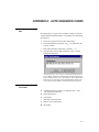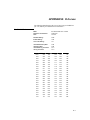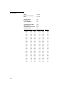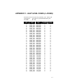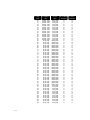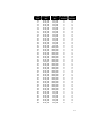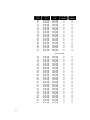
1
PRO-Soft QA-510
User Manual
SpO2 Analyzer
Copyright © 2000 by METRON. All rights reserved.
METRON:
USA
1345 Monroe NW, Suite 255A
Grand Rapids, MI 49505
Phone: (+1) 888 863-8766
Fax:
(+1) 616 454-3350
E-mail: [email protected]
FRANCE
30, rue Paul Claudel
91000 Evry, France
Phone: (+33) 1 6078 8899
Fax:
(+33) 1 6078 6839
E-mail: [email protected]
NORWAY
Travbaneveien 1
N-7044 Trondheim, Norway
Phone: (+47) 7382 8500
Fax:
(+47) 7391 7009
E-mail: [email protected]
License
By using the enclosed program and/or installing the files from the original disks to your hard drive, you are
agreeing to become bound by the terms of this agreement. If you do not agree to the terms of this agreement, return all
materials in this package to METRON U.S. within 30 days for a refund.
You have purchased a software license granting you the right to use the software contained herein. METRON
U.S. retains ownership of this software on the original disks, as well as any subsequent copies on any media or in any
form. METRON U.S. does not sell any rights to the software. METRON U.S. grants you the right to use the software
on the amount of computers for which you have purchased a License. If you wish to use this software for more computers than you have Licenses, you must purchase additional Licenses from METRON U.S.
Your License to the program contained in the software grants you, the purchaser, permission to use the program
for the purpose to which it was designed. The program files, in whole or in part, and all copyright or other intellectual and proprietary rights therein are and remain the property of METRON U.S.
THIS SOFTWARE IS LICENSED ONLY TO YOU, THE LICENSEE, AND MAY NOT BE TRANSFERRED
TO ANYONE WITHOUT THE WRITTEN CONSENT OF METRON U.S. Any authorized transferee of the software shall be bound by the terms and conditions of this License. In no event may you transfer, assign, rent, lease,
sell, or otherwise dispose of the software on a temporary or permanent basis except as expressly provided herein.
This License is governed by the State of Michigan and shall benefit METRON U.S., its successors, and assigns.
Licensee consents to jurisdiction in the state and federal courts located in the State of Michigan.
Limited Warranty/Disclaimer of Liability
METRON U.S. warrants that the software will substantially conform to published specifications and to the
documentation, provided that it is used on the computer hardware and with the operating system for which it was
designed. METRON U.S. will replace defective media or documentation, or correct substantial software errors at no
charge within 90 days of purchase. Contact METRON U.S. for information. If METRON U.S. is unable to correct
the problem, the License fee will be refunded to you. These are your sole remedies for any breach of warranty.
BECAUSE SOFTWARE IS INHERENTLY COMPLEX AND MAY NOT BE COMPLETELY
FREE OF ERRORS, YOU ARE ADVISED TO VERIFY YOUR WORK. In no event will METRON
U.S. be liable for direct, indirect, special, incidental, or consequential damages arising out of the use of
or inability to use the software or documentation, even if advised of the possibility of such damages.
METRON U.S. is not responsible for any costs, loss of profits, loss of data, or claims by third parties
due to use of, or inability to use the software.
Trademarks
IBM is a registered trademark, and PC/XT is a trademark of IBM Corporation. Microsoft is a registered trademark
and Windows is a trademark of Microsoft Corporation.
ii
Table of Contents
MANUAL REVISION RECORD .........................................................................................................V
1.
ABOUT PRO-SOFT QA-510 ..................................................................................................... 1-1
1.1
1.2
1.3
1.4
2.
GETTING STARTED................................................................................................................. 2-1
2.1
2.2
2.3
2.4
3.
Introduction ........................................................................................................................... 1-1
PRO-Soft QA-510 Testing .................................................................................................... 1-1
About your Manual................................................................................................................ 1-2
Updating PRO-Soft Program Files ........................................................................................ 1-2
System Requirements ............................................................................................................ 2-1
Installing PRO-Soft ............................................................................................................... 2-1
Initial Startup ......................................................................................................................... 2-2
Option Settings ...................................................................................................................... 2-4
TESTING SETUP........................................................................................................................ 3-1
3.1 Equipment Setup.................................................................................................................... 3-1
3.2 Initializing Remote Control ................................................................................................... 3-1
4.
SEQUENCE TESTING .............................................................................................................. 4-1
4.1 Sequence Form Window ....................................................................................................... 4-1
4.2 Sequence Setup...................................................................................................................... 4-2
5.
CHECKLISTS ............................................................................................................................. 5-1
5.1 Checklist Form Window........................................................................................................ 5-1
5.2 Checklist Files Management.................................................................................................. 5-1
6.
PROTOCOLS .............................................................................................................................. 6-1
6.1
6.2
6.3
6.4
7.
Protocol Form Window ......................................................................................................... 6-1
Protocol Database .................................................................................................................. 6-3
Protocol File Management..................................................................................................... 6-4
Importing Data....................................................................................................................... 6-5
R-CURVES .................................................................................................................................. 7-1
7.1 R-Curve Defined.................................................................................................................... 7-1
7.2 Creating R-Curves ................................................................................................................. 7-1
8.
TROUBLESHOOTING .............................................................................................................. 8-1
APPENDIX A: AUTO SEQUENCE CODES ..................................................................................A-1
A1 Auto Sequence Dialog Box ...................................................................................................A-1
A2 Auto Sequence Control Codes...............................................................................................A-1
A3 Auto Sequence Data Codes ...................................................................................................A-2
APPENDIX B: R-CURVES...............................................................................................................B-1
B1
BCI OXI-Pulse ......................................................................................................................B-1
iii
B2
B3
B4
B5
B6
B7
B8
B9
Criticare .................................................................................................................................B-2
Datascope Accutorr ...............................................................................................................B-3
Datex Satlite Trans ................................................................................................................B-4
Hewlett-Packard ....................................................................................................................B-5
Marquette Eagle.....................................................................................................................B-6
Nellcor ...................................................................................................................................B-7
Novametrix Oxypleth ............................................................................................................B-8
Ohmeda OxySTAT................................................................................................................B-9
APPENDIX C: LIGHT LEVEL CODES (L-CODES)....................................................................C-1
APPENDIX D: ERROR REPORT FORM, PRO-SOFT QA-510........................................................D-1
APPENDIX E: SUGGESTION FORM, PRO-SOFT QA-510 .......................................................E-2
iv
Manual Revision Record
This record page is for recording revisions to your PRO-Soft QA-510 User Manual that have been
published by METRON or its authorized representatives. We recommend that only the management or facility representative authorized to process changes and revisions to publications:
•
make the pen changes or insert the revised pages;
•
ensure that obsolete pages are withdrawn and either disposed of immediately, or marked as
superseded and placed in a superseded document file, and;
•
enter the information below reflecting that the revisions have been entered.
Rev No
Date Entered
Reason
0
-
Initial Release
Signature of Person Entering Change
v
This page intentionally left blank.
vi
1. About PRO-Soft QA-510
1.1 Introduction
Pulse Oximetry is a state-of-the-art, non-invasive method to determine the percentage of a patient's oxygen saturation (SaO2) without
having to obtain an arterial blood specimen. The instrument used for
this determination is a pulse oximeter. An oximeter measures the
changes in the intensity of transmitted light as blood pulsates through
a patient's finger or earlobe. From this data, the pulse oximeter does
mathematical calculations to determine the percentage of oxygen
saturation of the blood.
METRON’s QA-510 SpO2 Analyzer is a precision instrument for
testing these oximeters, and is designed for use by trained service
technicians. It allows the user to:
•
Simulate a variety of environmental and patient conditions.
•
Measure a pulse oximeter’s infrared and red LED.
•
Check the pulse oximeter’s ability to generate an alarm when
SpO2 or heart rate exceeds specified limits.
Testing with the QA-510 is usually a matter of setting up the preferred simulation parameters. Using PRO-Soft QA-510 simplifies the
process by providing an all Windows-based environment through
which simulation parameters are created by the user and sent to the
QA-510 unit. This in turn activates the corresponding simulation
state through the QA-510 Finger.
1.2 PRO-Soft QA-510
Testing
PRO-Soft QA-510 performs tests based on user generated test sequences and checklists. With the sequence tests you can perform simple or complex tests, including both the single and alarm limits test
modes, can be created and executed semi-automatically.
Test results are entered on the screen during testing. At the conclusion of testing the user may print a report, store the tests and results
on disk, or both. Combinations of tests can be created and stored as
“sequences.” PRO-Soft QA-510 maintains a library of these sequences. In this way the user can store and retrieve sequences that are
appropriate for the kind of equipment being tested.
Sequences can then be used independently, or can be attached to a
checklist, written procedure, and equipment data in the form of a test
1-1
“protocol.” The equipment data can be entered manually into the protocol, or it may be retrieved by PRO-Soft from other equipment files.
Protocols with test results can be printed, or stored on disk. Also, the
results of testing can be sent to other equipment maintenance management programs, to close a work order and update the oximeter’s
service history.
1.3 About your Manual
This manual is designed to assist you in the basic procedures for creating test protocols with PRO-Soft QA-510. It also covers all features
resident in the full PRO-Soft program.
Familiarity with Microsoft Windows and its features is assumed. If
you are unfamiliar with it, we recommend that you use your Microsoft Windows User’s Guide along with this manual.
This manual contains the following standardized text formatting conventions:
This
Represents
Bold title case
Menu items and control buttons that can be selected
to perform operations. The underline ( _ ) represents
the shortcut key. For example, “Select File, Save”
instructs you to press ”File,” then press “Save.“ The
comma (,) between selections indicates that both
selections are to be made in sequence.
< braces >
Text information that must be specified and entered
by the operator.
CAPITALS
File names and paths. For example, “QAMDAT.50”
The menu under discussion
1.4 Updating PRO-Soft
Program Files
Form
Sequence
Checklist
Protocol
F2
F3
F4
Occasionally, updated versions of PRO-Soft QA-510 program files
are posted on METRON’s Website at http://www.metron-biomed.
com. These can be downloaded through file transfer procedures. Registered users should contact their local METRON representative for
more information regarding updating.
1-2
2. Getting Started
2.1 System Requirements
The following are the minimum requirements for installation:
•
IBM PC/XT-compatible machine, 80486 SX 25 MHz or higher.
•
A 3.5" floppy drive.
•
An EGA, VGA, 8514, Hercules or compatible display (recommended: VGA).
•
8 MB of RAM.
•
1 MB of unoccupied hard disk space, plus 3 MB of free space on
the drive contained the WINDOWS:\SYSTEM directory.
•
Microsoft Windows version 3.11 or later version.
•
Metron QA-510.
•
RS-232 cable (null modem/data transfer configured).
•
Printer for reports. (MS-Windows compatible)
2.2 Installing PRO-Soft
1.
Start Windows.
2.
Insert the PRO-Soft QA-510 install disk # 1 into drive A
(or B) or insert the PRO-Soft CD into your CD drive.
3.
Select Run from the File Menu in the Windows Program
Manager. (In Win 95, click the Start button and then select Run.)
4.
Type <drive>:\setup. Then, click the OK button. If you are
installing PRO-Soft QA-510 from a CD, server or shared
directory, type the full path plus setup.
2-1
5. When setup starts, the following dialog box will appear.
Type in the desired drive and directory for PRO-Soft QA510, and then click the Continue button.
If you are installing PRO-Soft
QA-510 for the first time, we
recommend using the default
drive, directory, and program
group (C:\QA-510)
6.
After setup is completed, a program group will be created
in the Windows Program Manager called "PRO-Soft QA510," or another name you provided during installation.
7.
Remove the last disk or CD and store the installation
disk(s) in a safe place.
2.3 Initial Startup
The first time that PRO-Soft QA-510 is run, information has to be entered, and the program configured for further use.
2-2
1.
To start the program, double-click on the QA-510 icon.
2.
The following dialog box will appear. Enter the Establishment (license holder) name, and the Code (alphanumeric license number) exactly as written on the license
agreement supplied:
Be careful to enter the name
and code exactly as written
on the license agreement.
This screen is case sensitive.
3.
When you click the OK button the PRO-Soft QA-510
main application window is displayed:
2-3
2.4 Option Settings
To configure program parameters click the Option Menu, then
click Edit Options. The following five-card dialog box appears:
Options
Edit Options
In the topmost section of this box there are five tabs: PRO-Soft,
QA-510, QA-MAP, Report, and Interface. By clicking one of these
tabs, its corresponding card will be displayed, containing the settings
available for the item described on the tab.
After editing the option settings press OK to save changes, or Cancel
to discard them. When a <Path> text box is highlighted the Browse
button will also be available and, by pressing this button, a file window will be displayed where you can select the appropriate path.
1.
PRO-Soft Tab. This tab provides basic identification of the facility and operator of the test equipment, as well as pathing directions for the PRO-Soft program in order for it to function. The
configuration parameters and their descriptions are:
Operator:
The name of the person who is executing
the tests.
Language:
Language used for commands and menus
in PRO-Soft QA-510.
Path to the protocol
files:
Default path to the files where the test
protocols are stored.
Path to the sequence
files:
Default path to the files where the test
sequences are stored.
Path to the checklist
files:
Default path to the files where the test
checklists are stored.
Path to the procedure
files:
Default path to the files where the test
procedures are stored.
The operator and establishment settings, once made, become the
default settings, and appear automatically in the headings of
2-4
printed reports. To change the defaults, enter a new operator or
establishment and save by pressing OK.
2.
QA-510 Tab. This tab is used for three things. Setting the
communications port (COM1-4) to be utilized for initiating the
QA-510 remote setting at start-up. Once entered, it becomes the
default setting. To enter the serial number and firmware version
of the QA-510 utilized for testing. Once entered, it becomes the
default setting, and appears automatically in the headings of
printed reports. To change the default, enter a new serial number
and save by pressing OK.
3.
QA-MAP Tab. Most QA-MAP interaction control settings included in the PRO-Soft options may be changed during the execution of the PRO-Soft QA-MAP Program1. However, the following default settings are only available through the PRO-Soft
QA-510 options menu:
Path:
Path to the QA-MAP file QAMDAT.MDB.
List Equipment Codes:
Controls whether the equipment list window or
the equipment code text box window opens in
the fetch operation.
Fetch from QA-MAP:
- Appliance data
- Sequence
- Procedure
Sets the defaults as to the types of information
extracted from QA-MAP.
Once entered, these become the default settings. To change them,
enter new setting and save by pressing OK.
4.
Report Tab. This tab is for setting the alignment of the printouts for the test reports.
5.
Interface Tab. This tab is used to configure the PRO-Soft program by setting the input and output data files to be used when
interfacing with external programs. Once entered, it becomes the
default setting. To change the default, enter a new COM Port and
save by pressing OK.
1
Available separately from your Metron Representative.
2-5
This page intentionally left blank.
2-6
3. Testing Setup
Communication between the PRO-Soft QA-510 and the QA-510 is
based upon an RS-232C interface, that is standard on most modern
personal computers. The operation is essentially a “master-slave”
configuration, whereby the computer operates the QA-510.
3.1 Equipment Setup
Attach an RS-232 (null modem/data transfer configured) cable to the
9-pin D-sub outlet port located at the rear of the QA-510. Do not attach the printer cable to the QA-510. See below.
NOTE
Some RS-232C cables do
not have any connection
between the seventh and
the eighth wires in the
cable. The cable may still
be called a NULL-modem,
but it will not work with the
QA-510.
3.2 Initializing Remote
Control
1.
2.
Before initiating remote control, ensure that:
•
the RS-232C cable is securely connected to the communication ports on the QA-510 and your computer, and;
•
the proper communications port has been assigned.
With the QA-510 switched ON, advance to the Second Main
Menu Bar by pressing more-2 (F5):
3-1
⇑
3. Press REMOTE CONTR. (F4) to initiate remote control.
⇑
4.
3-2
Communication will be established when testing or downloading
of presets start.
4. Sequence Testing
Sequence testing enables you to perform multiple tests semi automatically. Instead of manually setting up and running one test at a
time, a sequence of several tests that you desire to perform can be set
up in advance of testing. Once a sequence is created you can save it
for later retrieval and reuse.
Up to 50 different tests can be run in each sequence. There are no restrictions on how the sequence is composed.
4.1 Sequence Form Window
Form
Sequence
Checklist
Protocol
F2
F3
F4
From the PRO-Soft QA-510 Main Menu select Form, Sequence, or
Form, Protocol, View Sequence and the Sequence Form Window
appears. The window displays a Control Field and two tabs: Single
test and Alarm limits test.
Each table row contains information for one test. Each column contains different parameters that can be selected to perform the tests.
4-1
1.
2.
2.
General parameters
Sequence
The name of the sequence.
R-Curve
The oximeter probe manufacturer from the preloaded or user-defined R-curve listing.
Sequence parameters
Test #
The test in sequential order.
Ambient light
The ambient light setting, which simulates motion,
ambient sunlight, and 50 Hz or 60 Hz artificial light
interfering with the pulse oximeter’s probe.
Pigmentation
The pigmentation setting (low, medium, high)
Preset
Simulated patient conditions. Default is Normal.
SpO2 [%]
The O2 saturation level. Range is 30% - 100%.
Rate [BPM]
The pulse rate. Range is 30-250 BPM.
P.Ampl.[%]
The pulse amplitude level. Range is 0% - 100%.
SpO2 Result
Key in the test result form your Pulse Oximeter
Rate Result
Key in the test result form your Pulse Oximeter
Warning
Key in the test result if the alarm triggered
Alarm Limits Test parameters. Information is contained in this
tab is for running alarm limits tests.
Test #
The test in sequential order.
Ambient light
The ambient light setting, which simulates motion,
ambient sunlight, and 50 Hz or 60 Hz artificial light
interfering with the pulse oximeter’s probe.
Pigmentation
The pigmentation setting (low, medium, high)
Test Parameter
The value simulated by the QA-510 unit. Select from
Pulse, SpO2, Rate, P.Ampl.
ALT Result
Alarm Test Result
Warning
Key in the test result if the alarm triggered
4.2 Sequence Setup
When the Sequence Window is opened the first test parameters for
Make, Amb.L. and Pigm. are set automatically so that, when new
tests are added to the sequence, these parameters are copied automatically to them. To modify or change these parameters, as well as
any other test parameters, click the field and manually enter the value
and press Enter or select from the drop down list of choices, as appropriate.
1.
4-2
Single Test Setup:
a.
Set the Make, Amb.L. and Pigm. parameters.
b.
Select one of the preprogrammed Preset states, or set SpO2,
Rate and P.ampl. manually.
2.
Alarm Limits Test Setup:
a.
Set the Make, Amb.L. and Pigm. parameters.
b.
Select the Test Parameter (SpO2, Rate or P.ampl.
4-3
This page intentionally left blank.
4-4
5. Checklists
The checklist adds manually or visually performed tests and function
checks to the protocols (see Chapter 7). Once created, a checklist can
be edited, stored and retrieved for future use.
5.1 Checklist Form Window
Form
Sequence
Checklist
Protocol
From the PRO-Soft QA-510 Main Menu select Form, Checklist.
The Checklist Form Window then appears (see below). It is a table
allowing for up to 30 lines, where each line contains a description of
what to examine (up to 50 characters). Each line also has two check
boxes, 'Pass' and 'Fail,' to be used when examining the infusion
pump.
F2
F3
F4
5.2 Checklist Files ManFile
agement
New
Load...
Save...
Save As...
Delete...
Print...
Exit
Ctl+N
Ctl+L
Ctl+S
Ctl+A
1.
New Checklist. Select File, New. The current checklist window
clears and initializes a new checklist form. If you already have an
active checklist containing unsaved changes, a dialog box appears. It prompts you as to whether or not you want to save the
changes, discard them, or abort the operation and return to the
active checklist.
2.
Loading and Saving Checklists. To save the active checklist,
select File, Save or File, Save As. The Checklist Library window will open (see below), prompting for a name to use for the
checklist. To retrieve, select File, Load and select among the
available checklists:
Ctl+P
5-1
3.
5-2
Printing Checklists. To print a checklist, select File, Print.
Then, select whether to print the checklist, or write it to a file.
6. Protocols
Protocol contains a description of the oximeter being tested, and
specifies an associated test sequence and checklist. It also includes a
procedure file, stating special concerns for each oximeter.
When saved, the results are added to PRO-Soft 510’s Protocol Database, or to QA-MAP, if installed. This database is an historical record
of those protocols for which safety tests have been done with
PRO-Soft. Information stored includes the:
•
Tested oximeter’s equipment code and serial number
•
Test sequence used in the test
•
Date the safety test was executed
•
Status of the test (OK, Failed)
•
Protocol filename containing the test results.
6.1 Protocol Form Window
Form
Sequence
Checklist
Protocol
F2
F3
F4
From the PRO-Soft QA-510 Main Menu select Form, Protocol and
the Protocol Form window appears:
6-1
The Protocol application window contains the following fields:
1.
Equipment Information Field. This field contains text boxes
that are used to describe the oximeter under test, and are also
used in the safety testing report to document the test of a particular oximeter. The text boxes, each containing space for up to 30
characters, are:
Equipment code:
The equipment identifier
Serial number:
The equipment serial number
Status:
The equipment status
Group:
The equipment group
Manufacturer:
Manufacturer of the equipment on test
Type:
The equipment type
Model:
The equipment model
Location:
Location of the equipment on test
PRO-Soft can load equipment information already entered in an
ASCII text file or, if you have PRO-Soft QA-MAP installed,
from that program. See paragraph 7.4.
2.
Remark Field. This field is for inserting remarks on the test. The
remark may contain up to 300 characters long, describing special
events that may have occurred during the testing. Any testing
anomalies peculiar to the equipment under test, or on the testing
itself, should be entered in this box.
3.
Procedure Field. This field is for detailing the testing procedure
used. For example, it can be a description of how to connect the
QA-510 to the instrument under test. Procedure is always saved
to a separate text file (*.txt). It can be created and edited by typing the information in the procedure text box or, by using any
text editor/word processor capable of saving plain text files (e.g.,
Windows Notepad). When you select an item in File, Procedure, the following dialog box appears where you can specify
the file you need by its filename. The title of the dialog box
shown depends on whether you select Load, Save or Save As. If
you have already saved the procedure, Save will store your
changes under the filename you specified the first time you saved
the file, while Save As will prompt you for a new filename.
4.
Sequence and Checklist Fields. These drop down list boxes
contain listings of all sequences and checklists resident in their
respective databases. Select which of them PRO-Soft will use to
test the equipment described in your protocol. When you have
selected a sequence and checklist the menu items Protocol, View
sequence and Protocol, View checklist become available. When
selecting either of these menu items PRO-Soft will load the sequence or checklist and switch to the respective application window, where you may edit it before running the test. If you already have an active sequence or checklist, containing unsaved
File
New protocol
Load
Save
Save As
Equipment data
Procedure
Import
Export
Print
Printer Setup
Exit
Protocol
View sequence
View checklist
Run test
Stop test
Library
6-2
Ctl+N
Ctl+L
Ctl+S
Ctl+A
Load
Save
Save As
F11
F12
changes, a dialog box appears, giving you an opportunity to save
the changes.
When first opening the protocol application window with a new
protocol these fields will be blank, indicating that no sequence or
checklist is connected to the protocol. They have to be created
and connected to the protocol before they will appear.
6.2 Protocol Database
Protocols are saved and retrieved from the Protocol Database (see below). This database is an historical record of those protocols for
which safety tests have been done with PRO-Soft. The information
stored includes the:
•
Tested oximeter’s equipment code and serial number
•
Test sequence used in the test
•
Date the safety test was executed
•
Status of the test (OK, Failed)
•
Protocol filename containing the test results.
To access the Protocol Library select Protocol, Library. The following dialog box appears:
The Protocol Database window contains the following fields:
1.
Equipment Code/Test Time. These list boxes contain the protocols already added to the database by equipment code and serial number.
2.
File name. This field shows the file name that the test history is
stored in.
3.
Control. The third field manages the database.
6-3
a.
Open loads the selected protocol into the active protocol
window, allowing you to view the safety test results and
other information stored in the protocol. If you already have
a protocol open in the active window, and this protocol contains unsaved changes, PRO-Soft will not load the protocol
selected in the database until you have responded to a dialog
box prompting you to save the open protocol.
b.
Delete removes selected protocol(s) from the library,
prompting for confirmation. Clicking No prevents deletion.
If more than one for deletion is selected, PRO-Soft will
leave the current equipment and continue to the next one selected, and display the message for this one.
c.
Cancel interrupts the entire delete operation. Note that
equipment protocols deleted before selecting Cancel (or No)
will not be restored.
d.
Refresh is used to update the display.
e.
Change Path is used to change the path that the files are
stored in.
f.
Update QA-MAP is designed specifically to update METRON’s QA-MAP. For this to operate QA-MAP must be installed, and the QA-MAP tab in Options, Edit Options
must be configured accordingly (cf. Paragraph 2.2.2). When
this button is clicked, PRO-Soft updates QA-MAP’s Test
table with the status of all test results added to the protocol
database since the last update operation. Included in the update is the:
•
Tested oximeter’s equipment code and serial number
•
Test sequence used in the test
•
Date the safety test was executed
•
Status of the test (OK, Failed)
•
PRO-Soft program executing the update (i.e., PRO-Soft
QA-510)
6.3 Protocol File Management
File
New protocol
Load
Save
Save As
Equipment data
Procedure
Import
Export
Print
Printer Setup
Exit
6-4
Ctl+N
Ctl+L
Ctl+S
Ctl+A
f
f
1.
New Protocol. Select File, New protocol. The system will display an empty Protocol Form window. Fill in the required information and select the test sequence and checklist to use with the
oximeter being tested.
You can open multiple protocols to allow you to compare, for
example, this year’s and last year’s test results. To do so select
Form, Protocol, and then open another protocol window by se-
lecting File, New Protocol. Then, select Window, Tile Horizontal, so that both forms appear together. To compare the test
results load the protocol corresponding to this year’s testing into
one of the protocol windows, and the protocol corresponding the
last year’s testing into the other window.
2.
Saving Protocols. Protocols are saved to the Protocol Database. To save the active protocol, select File, Save or File, Save
As. The Protocol Database window will open, and you will then
be prompted for a name to use for the protocol.
3.
Retrieving Protocols. There are two methods of retrieving protocols. One is to select File, Load and the other is to select Protocol, Library. Once the database window is opened, select
among the available protocols the one that is desired, and double
click to load it into the Protocol Form window.
4.
Printing Protocols. To print a protocol, select File, Print. Then,
select whether to print the protocol or write it to a file.
6.4 Importing Data
Equipment files pertaining to oximeters in the inventory can be created from ASCII text files, or can be imported into PRO-Soft QA510 from METRON’s QA-MAP program. This appendix details the
procedures for these options.
1.
File
New protocol
Load
Save
Save As
Equipment data
Procedure
Import
Export
Print
Printer Setup
Exit
Ctl+N
Ctl+L
Ctl+S
Ctl+A
From QA-MAP
From ASCIIfile
Retrieving from QA-MAP. Data on the oximeter to be tested
can be imported directly from METRON’s QA-MAP. For this
feature to operate QA-MAP must be installed, and the QA-MAP
tab in Options, Edit Options must be configured to reflect Retrieve Appliance Data. (cf. Paragraph 2.2.2).
To import the data select File, Equipment data, From
QA-MAP in the Main Menu.. When the following dialogue box
appears, select the appliance code for the oximeter you wish to
test and click on OK. Information stored in QA-MAP states,
which test sequence to use for each oximeter.
6-5
File
New protocol
Load
Save
Save As
Equipment data
Procedure
Import
Export
Print
Printer Setup
Exit
Ctl+N
Ctl+L
Ctl+S
Ctl+A
From QA-MAP
From ASCIIfile
2.
Making Protocol Formats from an ASCII Text File. PROSoft can load equipment information from an ASCII text file.
ASCII text files can be created on each of the oximeters for
which you intend to produce protocol formats. The ASCII file
must follow this pattern :
EquipCode
SerNo
Status
Group
Manufacturer
Model
Type
Location
Sequence Name
Procedure
=
=
=
=
=
=
=
=
=
=
<Equipment Code>
<Serial Number>
<Status>
<Group>
<Manufacturer>
<Model>
<Type>
<Location>
<Name of Test Sequence>
<Procedure Filename>
This file contains information on one oximeter. The text preceding the '=' sign is only for your convenience. The text following
the '=' sign is used to construct a protocol format. Make sure that
the lines appear in the right order, i.e., appliance code first, .... ,
procedure text last. Use a text editor or a word processor that can
save ASCII text to create the file (e.g., Notepad). To produce
protocol formats from the data in the file, select File, Equipment
data, From ASCII-file. Select the file containing the oximeter
information and click on OK. The program will read the file and
add one new protocol format to the database library for each
oximeter
6-6
7. R-Curves
7.1 R-Curve Defined
R-curves specify the relationship between the Red/IR ratio measured
by pulse oximeters and the SpO2 value displayed. These curves are
obtained by each pulse oximeter manufacturer during clinical trials.
QA-510 has pre-loaded manufacturer’s R-curves (see the Appendix B
for a listing). However, the operator may establish user-defined, or
additional manufacturer R-curves, and these can be loaded into the
PRO-Soft QA-510, and further downloaded into the QA-510.2
7.2 Creating R-Curves
QA-510
R-curve
To enter new, user-defined or factory R-curves, click the QA-510
Menu, then click R-curve. The following dialog box appears:
The form has two fields and a selection box. The upper field is the
R-curve name. The lower field is the file containing the R-curve itself. The selection box is where you select the target memory location in the QA-510 to store the R-Curve. The Make new R-curve
button will take you to the screen below and will use the selected Rcurve as a starting point for generation the new R-curve. Pressing
Upload R-curve, will upload the selected R-curve to the QA-510
into the selected memory slot.
2
Contact your local METRON Representative for a list of R-curves
currently available for download to the QA-510.
7-1
The Simple mode window contains the following fields and buttons:
1.
Sample no. This field is the sample number
2.
Perform Simulation. This field contains a checkbox. If the box
is checked the values will be simulated during the set of simulations.
3.
Simulated SpO2 Value. This is the SpO2 value that you wish to
simulate.
4.
SpO2 Result. This is the field where you key in the value that is
displayed on the SpO2 meter.
5.
Simulate SpO2 level. This button starts the simulation of the selected SpO2 values.
6.
Calculate R-Curve. This calculates the new R-curve based on
the results from the simulation. The more simulated points that
you use the more accurate the R-curve will be.
7.
Transfer R-Curve. This button is used to upload the R-curve
into the memory location in the QA-510 selected in the window
on the right.
When the mouse is over the table, you can press the right mouse button to insert additional test values or delete extra values.
7-2
In order to generate a valid new R-Curve for use by the QA-510,
you must work with a calibrated Pulse Oximeter unit or module,
a known good finger probe and a calibrated QA-510.
1.
2.
3.
4.
5.
6.
7.
8.
9.
10.
11.
12.
13.
14.
15.
16.
Launch PRO-Soft QA-510 on your computer and connect the
NULL-Modem cable from the COM port to the QA-510.
Turn on the QA-510 and the Pulse Oximeter.
On the QA-510, select through the different loaded R-Curves until you find the Make that functions best on the oximeter in question. (This will be the one that displays the closest correlation
between simulated and measured values.)
At this time you need to place the QA-510 into Remote Operation mode.
Within PRO-Soft QA-510, go to the menus at the top of the
screen. Select QA-510, then R-Curve. This will open the RCurve window.
In the scroll box you need to select the R-Curve data file that you
selected in step #3.
In the text box above the scroll box, type in the name for the new
R-Curve.
Now within the R-Curve window, select “File”, then “Save RCurve As”.
Do not select “Save R-Curve” or you will over write the data
for a currently calibrated R-Curve.
On the right side of the R-Curve window is a box where you can
select the memory position within the QA-510 to upload the new
R-Curve to. (The Default is the User-1 slot)
Press the “Make new R-Curve” button.
You are now in the R-Curve generation window. You will notice that in the upper right hand corner of the window it will indicate which R-Curve file you are currently editing. In the upper
left corner you will see two tabs; “Simple Mode” and “Advanced
Mode”. We suggest you start in simple mode.
The table on the screen is where you will set your test points.
This is done by selecting a cell in the “Simulated SpO2 Value”
column. To add more sample values to the table, right click
within the table and select “Insert Row”. We suggest testing at
99, 95, 90, 85 and so forth down to the lowest value that your
unit should properly display. (The more test points that you use,
the more accurate the calculated R-Curve will be.)
Once you have all of your test points selected, press the “Simulate SpO2 level” button.
Wait for the value on your SpO2 meter to stabilize then type it in
the selected “SpO2 Result” box and press “Enter” on your keyboard. This will send the next value to be simulated to the QA510.
Repeat step 14 until all values have been recorded.
Press the “Calculate R-Curve” Button.
7-3
17. Press the “Close” Button. This takes us back to our earlier RCurve window.
18. Go to “File” and select “Save R-Curve”. This will now save the
new R-Curve to your hard drive.
19. Make sure that the desired upload location is selected in the box
on the right, then press “Upload R-Curve”. The QA-510 will indicate, “Wait” while the data is uploading. Do not disconnect
the cable or turn off the power on the QA-510 during the
download.
20. Turn the power off on the QA-510. Wait 5 sec and turn the
power back on. This refreshes the data in the QA-510.
21. Test the new R-Curve in the QA-510 by selecting the Make that
you uploaded.
22. If the values are off go to step #4 and repeat the procedure now
using this data file as your starting point. Omit steps #7 and #8.
The Advanced mode window contains the following fields and buttons:
7-4
1.
Red Gain value. This field is the gain value for the Red source.
Legal values range from 100-2697.
2.
IR Gain value. This field is the gain value for the IR source.
Legal values range from 100-2697.
3.
Light Level code. This is the appropriate value selected from
the table in Appendix C. Legal values range from 0-255.
File
New R-Curve
Load R-Curve ...
Save R-Curve
Save R-Curve As ...
Ctl+L
Ctl+S
4.
SpO2 Value and R-Value. These are the fields where the SpO2
value and its respective R-value are listed.
5.
New R-Value. This is where you can enter in a new R-value.
Legal Values are 0-2.55.
6.
Calculate R-Curve. This calculates the new R-curve based on
the results from the simulation. The more simulated points that
you use the more accurate the R-curve will be.
2.
Transfer R-Curve. This button is used to upload the R-curve
into the memory location in the QA-510 selected in the window
on the right.
Edit
Clear R-values
When you opened Specify R-curve, and the R-curve dialog box appeared, the control menu contents also changed. When R-curve operations are completed, and you exit R-curve, the control menu contents revert to that of the main application window.
The File menu, shown at the left, allows you to create New, or Load
R-curves already resident in the R-curve directory. Selecting Save
saves the current R-curve to a file in the R-curve directory. Selecting
Save As saves the current R-curve to a file in the R-curve directory.
The R-curve values in the table can be cleared by selecting Edit, C
lear R-Values. R-Curves can be saved and loaded from the File
menu.
Once the R-curve is entered transfer it to the QA-510 by either clicking the Transfer R-Curve button, or selecting QA-510, Transfer RCurve from the main application menu. As the R-curve is being
transferred the QA-510 will flash, “Wait!” in the lower right part of
its display, and the hourglass in the lower left part of the PRO-Soft
QA-510 display will start rotating. When the QA-510 stops flashing,
“Wait!” and the hourglass in the PRO-Soft QA-510 stops rotating,
the transfer is complete.
If the QA-510 serial number was entered in the Options, QA-510 tab
(see paragraph 2.3.2), PRO-Soft QA-510 will save the name of the
R-Curve you just transferred. This enables PRO-Soft to display the
correct make while executing tests.
7-5
This page intentionally left blank.
7-6
8. Troubleshooting
Problem
Possible Solution
Communication not established between
the computer and the QA-510.
Check to ensure that:
1.
The QA-510 is set to “Remote Control.”
2.
The correct COM-Port is assigned in the
Options Menu.
3.
The RS-232 cable has a null modem/data
transfer configuration.
Test sequence grid will not accept data
Check the tests to be made in the 'Tests' frame.
Reports are not printed
1.
Wrong printer driver. Choose the correct printer
when running print report.
2.
Do not check the print to file box when running
print report.
Strange characters in a report
Wrong printer driver. Choose the appropriate printer
in the Print Manager program.
8-1
This page intentionally left blank.
8-2
APPENDIX A: AUTO SEQUENCE CODES
A1 Auto Sequence Dialog
Box
This dialog box (see figure below) contains a string of codes, developed from the following tables. Conventions for constructing
the string are:
a.
There are no spaces between codes in the string.
b.
The Load Sequence in position ( “Q__” ) is followed in all
cases by a colon.
c.
Each code inserted is followed by a comma ( “,” ).
d.
The last code is always End of sequence ( “E” ), with no
punctuation thereafter.
Description of above auto sequence: Load Auto Sequence in position 01, Make: Novametrix, Ambient light: Normal, Pigment: Low,
Preset: Normal, Wait for user to press advance, Preset: Weak Pulse,
Wait for user to press advance, Preset: Bradycardia, Wait for user
to press advance, Print Header, Print Status, End Auto Sequence.
A2 Auto Sequence Control Codes
Q = Load Auto Sequence in position “nn” (Example: “Q01” = Load
Auto Sequence in position 01).
E
= End Auto Sequence
H
= Print Header
I
= Enter Alarm Limits Test Mode
K
= Wait for user to press advance
W = Print status
A-1
A3 Auto Sequence Data
Codes
M = Pre-loaded manufacturer’s or user-defined r-curve (Example: “M01”
= BCI Oxi-Pulse)
Code
Description
Code
Description
M01
BCI Oxi-Pulse
M09
Ohmeda
M02
Criticare
M10
User Defined 1
M03
Datascope
M11
User Defined 2
M04
Datex
M12
User Defined 3
M05
Novametrix
M13
User Defined 4
M06
Marquette Electronics
M14
User Defined 5
M07
Nellcor
M15
User Defined 6
M08
Hewlett-Packard
M16
User Defined 7
L = Ambient light (Example: “L01” = Normal)
Code
Description
L01
Normal
L02
50 MHz
L03
60 MHz
L04
Sun
P = Pigment (Example: “L01” = Normal)
Code
Description
P01
Low
P02
Medium
P03
High
R = Maximum and minimum ranges for QA-510 settings (Example:
“R07” = PulseMax/Asystole)
Code
Description
Code
Description
R01
SpO2 Max
R05
Pampl Max
R02
SpO2 Min
R06
Pampl Min
R03
Rate Max
R07
Pulse Max
R04
Rate Min
R08
Pulse Min
S = SpO2 from 35 to 100%. This is entered in three-digit format. (For
example, an SpO2 of 35% = S035)
T = Preset (Example: “T06” = Geriatric)
Code
Description
Code
Description
T01
Manual
T05
Tachycardia
T02
Normal
T06
Geriatric
T03
Weak Pulse
T07
Obese
T04
Bradycardia
T08
Motion
A = Pulse Amplitude from 0 to 100%. This is entered in three-digit format. (For example, a pulse amplitude of 10 percent = A010)
A-2
B = Rate from 0 to 300 BPM. This is entered in three-digit format. (For
example, a BPM rate of 65 = B065)
D = Delay in tenths of a seconds from 1 to 999. This is entered in threedigit format. (For example, a delay of 10 seconds = D100)
A-3
This page intentionally left blank.
A-4
APPENDIX B: R-Curves
The following manufacturers’ R-Curves have been pre-loaded into
QA-510, and are provided herein for information.
B1 BCI OXI-Pulse
Make:
Reference Unit Serial No.:
Date:
BCI OXI-PULSE 3301 71000A1
320014767
04.03.97
Red Gain Setting:
IR Gain Setting:
Level Code Setting:
2048
1024
101
Broadband Preamp Gain:
IR Preamp Gain:
Broadband Trig Threshold:
IR Trig Threshold:
0 dB
0 dB
0.5 V
0.5 V
SpO2
R-value
SpO2
R-value
SpO2
R-value
100%
0.39
78%
1.03
56%
1.57
99%
0.46
77%
1.05
55%
1.60
98%
0.53
76%
i .07
54%
1.63
97%
0.59
75%
1.09
53%
1.66
96%
0.63
74%
1.11
52%
1.69
95%
0.66
73%
1.13
51%
1.73
94%
0.69
72%
1.16
50%
1.76
93%
0.71
71%
1.18
49%
1.80
92%
0.74
70%
1.20
46%
1.83
91%
0.76
69%
1.23
47%
1.87
90%
0.78
68%
1.25
46%
1.90
89%
0.80
67%
1.27
45%
1.94
88%
0.83
66%
1.30
44%
1.98
87%
0.85
65%
1.32
43%
2.02
86%
0.87
64%
1.35
42%
2.06
85%
0.89
63%
1.37
41%
2.10
84%
0.91
62%
1.40
40%
2.14
83%
0.93
61%
1.43
39%
2.18
82%
0.95
60%
1.45
38%
2.23
81%
0.97
59%
1.48
37%
2.27
80%
0.99
58%
1.51
36%
2.31
79%
1.01
57%
1.54
35%
2.36
B-1
B2 Criticare
B-2
Make:
Reference Unit Serial No.:
Date:
Criticare
Red Gain Setting:
IR Gain Setting:
Level Code Setting:
400
325
101
Broadband Preamp Gain:
IR Preamp Gain:
Broadband Trig Threshold:
IR Trig Threshold:
0 dB
0 dB
0.5 V
0.5 V
04.03.97
SpO2
R-value
SpO2
R-value
SpO2
R-value
100%
0.44
78%
1.10
56%
1.56
99%
0.50
77%
1.12
55%
1.58
98%
0.55
76%
1.15
54%
1.60
97%
0.59
75%
1.17
53%
1.62
96%
0.63
74%
1.19
52%
1.65
95%
0.66
73%
1.21
5i%
1.67
94%
0.69
72%
1.23
50%
1.70
93%
0.72
71%
1.26
49%
1.73
92%
0.74
70%
1.28
48%
1.76
91%
0.77
69%
1.30
47%
1.78
90%
0.79
68%
1.32
46%
1.81
89%
0.82
67%
1.34
45%
1.85
88%
0.84
66%
1.36
44%
1.88
87%
0.87
65%
1.38
43%
1.91
86%
0.89
64%
1.39
42%
1.95
85%
0.92
63%
1.41
41%
1.98
84%
0.95
62%
1.43
40%
2.02
83%
0.97
61%
1.45
39%
2.06
82%
1.00
60%
1.47
38%
2.10
81%
1.02
59%
1.49
37%
2.13
80%
1.05
58%
1.51
36%
2.17
79%
1.07
57%
1.53
35%
2.21
B3 Datascope Accutorr
Make:
Reference Unit Serial No.:
Date:
Datascope Accutorr 3 Sat
10995F2
04.03.97
Red Gain Setting:
IR Gain Setting:
Level Code Setting:
2048
1024
110
Broadband Preamp Gain:
IR Preamp Gain:
Broadband Trig Threshold:
IR Trig Threshold:
0 dB
0 dB
2V
1V
SpO2
R-value
SpO2
R-value
SpO2
R-value
100%
0.49
78%
1.22
56%
1.75
99%
0.53
77%
1.25
55%
1.77
98%
0.56
76%
1.28
54%
1.79
97%
0.61
75%
1.31
53%
1.81
96%
0.63
74%
1.33
52%
1.83
95%
0.67
73%
1.36
51%
1.85
94%
0.72
72%
1.38
50%
1.87
93%
0.75
71%
1.41
49%
1.89
92%
0.79
70%
1.43
48%
1.91
91%
0.82
69%
1.46
47%
1.92
90%
0.86
68%
1.48
46%
1.94
89%
0.89
67%
1.51
45%
1.96
88%
0.92
66%
1.53
44%
1.98
87%
0.96
65%
1.55
43%
2.00
86%
0.99
64%
1.58
42%
2.01
85%
1.02
63%
1.60
41%
2.03
84%
1.05
62%
1.62
40%
2.05
83%
1.08
61%
1.64
39%
2.06
82%
1.11
60%
1.67
38%
2.08
81%
1.14
59%
1.69
37%
2.10
80%
1.17
58%
1.71
36%
2.11
79%
1.20
57%
1.73
35%
2.13
B-3
B4 Datex Satlite Trans
B-4
Make:
Reference Unit Serial No.:
Date:
Datex Satlite Trans
10995F2
04.03.97
Red Gain Setting:
IR Gain Setting:
Level Code Setting:
2048
1024
11
Broadband Preamp Gain:
IR Preamp Gain:
Broadband Trig Threshold:
IR Trig Threshold:
-14 dB
-8 dB
1V
2V
SpO2
R-value
SpO2
R-value
SpO2
R-value
100%
0.38
78%
1.09
56%
1.54
99%
0.47
77%
1.12
55%
1.56
98%
0.54
76%
1.14
54%
1.58
97%
0.59
75%
1.16
53%
1.60
96%
0.63
74%
1.18
52%
1.62
95%
0.67
73%
1.20
51%
1.64
94%
0.70
72%
1.22
50%
1.66
93%
0.73
71%
1.24
49%
1.68
92%
0.75
70%
1.26
48%
1.70
91%
0.78
69%
1.29
47%
1.72
90%
0.81
68%
1.31
46%
1.74
89%
0.83
67%
1.33
45%
1.76
88%
0.86
66%
1.35
44%
1.78
87%
0.88
65%
1.37
43%
1.80
86%
0.91
64%
1.39
42%
1.82
85%
0.93
63%
1.41
41%
1.84
84%
0.96
62%
1.43
40%
1.86
83%
0.98
61%
1.45
39%
1.88
82%
1.00
60%
1.47
38%
1.90
81%
1.03
59%
1.49
37%
1.93
80%
1.05
58%
1.51
36%
1.95
79%
1.07
57%
1.52
35%
1.98
B5 Hewlett-Packard
Make:
Reference Unit Serial No.:
Date:
Hewlett-Packard
Red Gain Setting:
IR Gain Setting:
Level Code Setting:
480
640
96
Broadband Preamp Gain:
IR Preamp Gain:
Broadband Trig Threshold:
IR Trig Threshold:
0 dB
0 dB
0.25 V
0.25 V
04.03.97
SpO2
R-value
SpO2
R-value
SpO2
R-value
100%
0.64
78%
1.29
56%
1.76
99%
0.68
77%
1.31
55%
1.77
98%
0.71
76%
1.34
54%
1.79
97%
0.74
75%
1.36
53%
1.81
96%
0.78
74%
1.38
52%
1.83
95%
0.81
73%
1.41
51%
1.85
94%
0.84
72%
1.43
50%
1.87
93%
0.87
71%
1.45
49%
1.89
92%
0.90
70%
1.47
48%
1.90
91%
0.93
69%
1.49
47%
1.92
90%
0.96
68%
1.52
46%
1.94
89%
0.99
67%
1.54
45%
1.96
88%
1.02
66%
1.56
44%
1.98
87%
1.05
65%
1.58
43%
1.99
86%
1.08
64%
1.60
42%
2.01
85%
1.11
63%
1.62
41%
2.03
84%
1.14
62%
1..64
40%
2.04
83%
1.16
61%
1.66
39%
2.06
82%
1.19
60%
1.68
38%
2.08
81%
1.21
59%
1.70
37%
2.09
80%
1.24
58%
1.72
36%
2.11
79%
1.26
57%
1.74
35%
2.12
B-5
B6 Marquette Eagle
B-6
Make:
Reference Unit Serial No.:
Date:
Marquette Eagle 3000
H5LA0215G
04.03.97
Red Gain Setting:
IR Gain Setting:
Level Code Setting:
2048
1024
101
Broadband Preamp Gain:
IR Preamp Gain:
Broadband Trig Threshold:
IR Trig Threshold:
0 dB
0 dB
0.5 V
0.5 V
SpO2
R-value
SpO2
R-value
SpO2
R-value
100%
0.50
78%
1.06
56%
1.41
99%
0.53
77%
1.08
55%
1.43
98%
0.57
76%
1.10
54%
1.44
97%
0.60
75%
1.12
53%
1.46
96%
0,63
74%
1,13
52%
1,47
95%
0.66
73%
1.15
51%
1.49
94%
0.69
72%
1.17
50%
1.50
93%
0.72
71%
1.18
49%
1.52
92%
0.75
70%
1.20
46%
1.53
91%
0.77
69%
1.22
47%
1.55
90%
0.80
68%
1.23
46%
1.57
89%
0.83
67%
1.25
45%
1.58
88%
0.85
66%
1.26
44%
1.60
87%
0.88
65%
1.28
43%
1.61
86%
0.90
64%
1.29
42%
1.63
85%
0.92
63%
1.31
41%
1.64
64%
0.94
62%
1.32
40%
1.66
83%
0.96
61%
1.34
39%
1.67
82%
0.99
60%
1.35
38%
1.69
81%
1.01
59%
1.37
37%
1.70
80%
1.03
58%
1.38
36%
1.72
79%
1.04
57%
1.40
35%
1.73
B7 Nellcor
Make:
Reference Unit Serial No.:
Date:
Nellcor N-20
207 74 771
04.03.97
Red Gain Setting:
IR Gain Setting:
Level Code Setting:
2048
1024
101
Broadband Preamp Gain:
IR Preamp Gain:
Broadband Trig Threshold:
IR Trig Threshold:
0 dB
0 dB
0.5 V
0.5 V
SpO2
R-value
SpO2
R-value
SpO2
R-value
100%
0.48
78%
1.05
56%
1.40
99%
0.52
77%
1.07
55%
1.42
98%
0.55
76%
1.09
54%
1.43
97%
0.59
75%
1.11
53%
1.45
96%
0.62
74%
1.12
52%
1.46
95%
0.65
73%
1.14
51%
1.48
94%
0.68
72%
1.16
50%
1.49
93%
0.71
71%
1.17
49%
1.51
92%
0.74
70%
1.19
48%
1.52
91%
0.77
69%
1.21
47%
1.54
90%
0.79
68%
1.22
46%
1.55
89%
0.82
67%
1.24
45%
1.57
88%
0.84
68%
1.25
44%
1.59
87%
0.87
65%
1.27
43%
1.60
86%
0.89
64%
1,28
42%
1.62
85%
0.91
63%
1.30
41%
1.63
84%
0.93
62%
1.31
40%
1.65
83%
0.95
61%
1.33
39%
1.66
82%
0.98
60%
1.34
38%
1.68
81%
1.00
59%
1.36
37%
1.69
80%
1.02
58%
1.37
36%
1.71
79%
1.03
57%
1.39
35%
1.72
B-7
B8 Novametrix Oxypleth
Reference Unit Serial No.:
Date:
Novametrix Oxyp!eth
Model 520A
77 - 3766LR
04.03.97
Red Gain Setting:
IR Gain Setting:
Level Code Setting:
1030
1520
10
Broadband Preamp Gain:
IR Preamp Gain:
Broadband Trig Threshold:
IR Trig Threshold:
-14 dB
-8 dB
1V
1V
Make:
B-8
SpO2
R-value
SpO2
R-value
SpO2
R-value
100%
0.43
78%
1.26
56%
1.76
99%
0.51
77%
1.29
55%
1.79
98%
0.59
76%
1.31
54%
1.81
97%
0.66
75%
1.34
53%
1.83
98%
0.72
74%
1.36
52%
1.85
95%
0.75
73%
1.38
51%
1.86
94%
0.78
72%
1.40
50%
1.88
93%
0.81
71%
1.42
49%
1.88
92%
0.84
70%
1.44
48%
1.88
91%
0.87
69%
1.47
47%
1.88
90%
0.90
88%
1.49
46%
1.88
89%
0.93
67%
1.51
45%
1.88
88%
0.97
66%
1.53
44%
1.88
87%
1.00
65%
1.55
43%
1.88
86%
1.03
64%
1.57
42%
1.88
85%
1.06
63%
1.60
41%
1.88
84%
1.09
62%
1.62
40%
1,88
83%
1.12
61%
1.64
39%
1.88
82%
1.15
60%
1.67
38%
1.88
81%
1.18
59%
1.69
37%
1.88
80%
1.21
58%
1.72
36%
1.88
79%
1.24
57%
1.74
35%
1.88
B9 Ohmeda OxySTAT
Make:
Reference Unit Serial No.:
Date:
Ohmeda OxySTAT
Red Gain Setting:
IR Gain Setting:
Level Code Setting:
480
640
96
Broadband Preamp Gain:
IR Preamp Gain:
Broadband Trig Threshold:
IR Trig Threshold:
0 dB
0 dB
0.25 V
0.25 V
04.03.97
SpO2
R-value
SpO2
R-value
SpO2
R-value
100%
0.53
78%
1.26
56%
1.77
99%
0.57
77%
1.29
55%
1.79
98%
0.60
76%
1.31
54%
1.82
97%
0.64
75%
1.34
53%
1.84
96%
0.68
74%
1.36
52%
1.86
95%
0.72
73%
1.39
51%
1.88
94%
0.76
72%
1.41
50%
1.90
93%
0.79
71%
1.43
49%
1.92
92%
0.83
70%
1.46
48%
1.95
91%
0.86
69%
1.48
47%
1.97
90%
0.90
68%
1.50
46%
1.99
89%
0.93
67%
1.53
45%
2.01
88%
0.96
66%
1.55
44%
2.03
87%
1.00
65%
1.57
43%
2.05
86%
1.03
64%
1.59
42%
2.07
85%
1.06
63%
1.62
41%
2.08
84%
1.09
62%
1.64
40%
2.10
83%
1.12
61%
1.66
39%
2.12
82%
1.15
60%
1.68
38%
2.13
81%
1.18
59%
1.70
37%
2.15
80%
1.21
58%
1.73
36%
2.16
79%
1.23
57%
1.75
35%
2.18
B-9
This page intentionally left blank.
B-10
APPENDIX C: LIGHT LEVEL CODES (L-CODES)
Broad Band Channel: PLUS_8dB, PLUS_0dB, MINUS_13dB, MINUS_14dB
Infrared Channel:
PLUS_6dB, PLUS_0dB, MINUS6dB, MINUS_8dB
L1 = 0.25V
L3 = 1V
L2 = 0.5V
L4 = 2V
L(evel)
Code
Broad Band
Gain
Infrared
Gain
Broad Band
Threshold
Infrared
Threshold
00
01
02
03
04
05
06
07
08
09
10
11
12
13
14
15
16
17
18
19
20
21
22
23
24
25
26
27
28
29
30
31
32
33
34
35
36
37
38
39
40
41
42
43
44
45
46
47
48
MINUS_14dB
MINUS_14dB
MINUS_14dB
MINUS_14dB
MINUS_14dB
MINUS_14dB
MINUS_14dB
MINUS_14dB
MINUS_14dB
MINUS_14dB
MINUS_14dB
MINUS_14dB
MINUS_14dB
MINUS_14dB
MINUS_14dB
MINUS_14dB
MINUS_14dB
MINUS_14dB
MINUS_14dB
MINUS_14dB
MINUS_14dB
MINUS_14dB
MINUS_14dB
MINUS_14dB
MINUS_14dB
MINUS_14dB
MINUS_14dB
MINUS_14dB
MINUS_14dB
MINUS_14dB
MINUS_14dB
MINUS_14dB
MINUS_14dB
MINUS_14dB
MINUS_14dB
MINUS_14dB
MINUS_14dB
MINUS_14dB
MINUS_14dB
MINUS_14dB
MINUS_14dB
MINUS_14dB
MINUS_14dB
MINUS_14dB
MINUS_14dB
MINUS_14dB
MINUS_14dB
MINUS_14dB
MINUS_14dB
MINUS_8dB
MINUS_8dB
MINUS_8dB
MINUS_8dB
MINUS_8dB
MINUS_8dB
MINUS_8dB
MINUS_8dB
MINUS_8dB
MINUS_8dB
MINUS_8dB
MINUS_8dB
MINUS_8dB
MINUS_8dB
MINUS_8dB
MINUS_8dB
MINUS_6dB
MINUS_6dB
MINUS_6dB
MINUS_6dB
MINUS_6dB
MINUS_6dB
MINUS_6dB
MINUS_6dB
MINUS_6dB
MINUS_6dB
MINUS_6dB
MINUS_6dB
MINUS_6dB
MINUS_6dB
MINUS_6dB
MINUS_6dB
PLUS_0dB
PLUS_0dB
PLUS_0dB
PLUS_0dB
PLUS_0dB
PLUS_0dB
PLUS_0dB
PLUS_0dB
PLUS_0dB
PLUS_0dB
PLUS_0dB
PLUS_0dB
PLUS_0dB
PLUS_0dB
PLUS_0dB
PLUS_0dB
PLUS_6dB
L1
L1
L1
L1
L2
L2
L2
L2
L3
L3
L3
L3
L4
L4
L4
L4
L1
L1
L1
L1
L2
L2
L2
L2
L3
L3
L3
L3
L4
L4
L4
L4
L1
L1
L1
L1
L2
L2
L2
L2
L3
L3
L3
L3
L4
L4
L4
L4
L1
L1
L2
L3
L4
L1
L2
L3
L4
L1
L2
L3
L4
L1
L2
L3
L4
L1
L2
L3
L4
L1
L2
L3
L4.
L1
L2
L3
L4
L1
L2
L3
L4
L1
L2
L3
L4
L1
L2
L3
L4
L1
L2
L3
L4
L1
L2
L3
L4
L1
C-1
C-2
L(evel)
Code
Broad Band
Gain
Infrared
Gain
Broad Band
Threshold
Infrared
Threshold
49
50
51
52
53
54
55
56
57
58
59
60
61
62
63
64
65
66
67
68
69
70
71
72
73
74
75
76
77
78
79
80
81
82
83
84
85
86
87
88
89
90
91
92
93
94
95
96
97
98
99
100
101
102
103
104
105
106
107
108
MINUS_14dB
MINUS_14dB
MINUS_14dB
MINUS_14dB
MINUS_14dB
MINUS_14dB
MINUS_14dB
MINUS_14dB
MINUS_14dB
MINUS_14dB
MINUS_14dB
MINUS_14dB
MINUS_14dB
MINUS_14dB
MINUS_14dB
PLUS_0dB
PLUS_0dB
PLUS_0dB
PLUS_0dB
PLUS_0dB
PLUS_0dB
PLUS_0dB
PLUS_0dB
PLUS_0dB
PLUS_0dB
PLUS_0dB
PLUS_0dB
PLUS_0dB
PLUS_0dB
PLUS_0dB
PLUS_0dB
PLUS_0dB
PLUS_0dB
PLUS_0dB
PLUS_0dB
PLUS_0dB
PLUS_0dB
PLUS_0dB
PLUS_0dB
PLUS_0dB
PLUS_0dB
PLUS_0dB
PLUS_0dB
PLUS_0dB
PLUS_0dB
PLUS_0dB
PLUS_0dB
PLUS_0dB
PLUS_0dB
PLUS_0dB
PLUS_0dB
PLUS_0dB
PLUS_0dB
PLUS_0dB
PLUS_0dB
PLUS_0dB
PLUS_0dB
PLUS_0dB
PLUS_0dB
PLUS_0dB
PLUS_6dB
PLUS_6dB
PLUS_6dB
PLUS_6dB
PLUS_6dB
PLUS_6dB
PLUS_6dB
PLUS_6dB
PLUS_6dB
PLUS_6dB
PLUS_6dB
PLUS_6dB
PLUS_6dB
PLUS_6dB
PLUS_6dB
MINUS_8dB
MINUS_8dB
MINUS_8dB
MINUS_8dB
MINUS_8dB
MINUS_8dB
MINUS_8dB
MINUS_8dB
MINUS_8dB
MINUS_8dB
MINUS_8dB
MINUS_8dB
MINUS_8dB
MINUS_8dB
MINUS_8dB
MINUS_8dB
MINUS_6dB
MINUS_6dB
MINUS_6dB
MINUS_6dB
MINUS_6dB
MINUS_6dB
MINUS_6dB
MINUS_6dB
MINUS_6dB
MINUS_6dB
MINUS_6dB
MINUS_6dB
MINUS_6dB
MINUS_6dB
MINUS_6dB
MINUS_6dB
PLUS_0dB
PLUS_0dB
PLUS_0dB
PLUS_0dB
PLUS_0dB
PLUS_0dB
PLUS_0dB
PLUS_0dB
PLUS_0dB
PLUS_0dB
PLUS_0dB
PLUS_0dB
PLUS_0dB
L1
L1
L1
L2
L2
L2
L2
L3
L3
L3
L3
L4
L4
L4
L4
L1
L1
L1
L1
L2
L2
L2
L2
L3
L3
L3
L3
L4
L4
L4
L4
L1
L1
L1
L1
L2
L2
L2
L2
L3
L3
L3
L3
L4
L4
L4
L4
L1
L1
L1
L1
L2
L2
L2
L2
L3
L3
L3
L3
L4
L2
L3
L4
L1
L2
L3
L4
L1
L2
L3
L4
L1
L2
L3
L4
L1
L2
L3
L4
L1
L2
L3
L4
L1
L2
L3
L4
L1
L2
L3
L4
L1
L2
L3
L4
L1
L2
L3
L4
L1
L2
L3
L4
L1
L2
L3
L4
L1
L2
L3
L4
L1
L2
L3
L4
L1
L2
L3
L4
L1
L(evel)
Code
Broad Band
Gain
Infrared
Gain
Broad Band
Threshold
Infrared
Threshold
109
110
111
112
113
114
115
116
117
118
119
120
121
122
123
124
125
126
127
128
129
130
131
132
133
134
135
136
137
138
139
140
141
142
143
144
145
146
147
148
149
150
151
152
153
154
155
156
157
158
159
160
161
162
163
164
165
166
167
168
PLUS_0dB
PLUS_0dB
PLUS_0dB
PLUS_0dB
PLUS_0dB
PLUS_0dB
PLUS_0dB
PLUS_0dB
PLUS_0dB
PLUS_0dB
PLUS_0dB
PLUS_0dB
PLUS_0dB
PLUS_0dB
PLUS_0dB
PLUS_0dB
PLUS_0dB
PLUS_0dB
PLUS_0dB
PLUS_8dB
PLUS_8dB
PLUS_8dB
PLUS_8dB
PLUS_8dB
PLUS_8dB
PLUS_8dB
PLUS_8dB
PLUS_8dB
PLUS_8dB
PLUS_8dB
PLUS_8d0
PLUS_8dB
PLUS_8dB
PLUS_8dB
PLUS_8dB
PLUS_8dB
PLUS_8dB
PLUS_8dB
PLUS_8dB
PLUS_8dB
PLUS_8dB
PLUS_8dB
PLUS_8dB
PLUS_8dB
PLUS_8dB
PLUS_8dB
PLUS_8dB
PLUS_8dB
PLUS_8dB
PLUS_8dB
PLUS_8dB
PLUS_8dB
PLUS_8dB
PLUS_8dB
PLUS_8dB
PLUS_8dB
PLUS_8dB
PLUS_8dB
PLUS_8dB
PLUS_8dB
PLUS_0dB
PLUS_0dB
PLUS_0dB
PLUS_6dB
PLUS_6dB
PLUS_6dB
PLUS_6dB
PLUS_6dB
PLUS_6dB
PLUS_6dB
PLUS_6dB
PLUS_6dB
PLUS_6dB
PLUS_6dB
PLUS_6dB
PLUS_6dB
PLUS_6dB
PLUS_6dB
PLUS_6dB
MINUS_8dB
MINUS_8dB
MINUS_8dB
MINUS_8dB
MINUS_8dB
MINUS_8dB
MINUS_8dB
MINUS_8dB
MINUS_8dB
MINUS_8dB
MINUS_8dB
MINUS_8dB
MINUS_8dB
MINUS_8dB
MINUS_8dB
MINUS_8dB
MINUS_6dB
MINUS_6dB
MINUS_6dB
MINUS_6dB
MINUS_6dB
MINUS_6dB
MINUS_6dB
MINUS_6dB
MINUS_6dB
MINUS_6dB
MINUS_6dB
MINUS_6dB
MINUS_6dB
MINUS_6dB
MINUS_6dB
MINUS_6dB
PLUS_0dB
PLUS_0dB
PLUS_0dB
PLUS_0dB
PLUS_0dB
PLUS_0dB
PLUS_0dB
PLUS_0dB
PLUS_0dB
L4
L4
L4
L1
L1
L1
L1
L2
L2
L2
L2
L3
L3
L3
L3
L4
L4
L4
L4
L1
L1
L1
L1
L2
L2
L2
L2
L3
L3
L3
L3
L4
L4
L4
L4
L1
L1
L1
L1
L2
l.2
L2
L2
L3
L3
L3
L3
L4
L4
L4
L4
L1
L1
L1
L1
L2
L2
L2
L2
L3
L2
L3
L4
L1
L2
L3
L4
L1
L2
L3
L4
L1
L2
L3
L4
L1
L2
L3
L4
L1
L2
L3
L4
L1
L2
L3
L4
L1
L2
L3
L4
L1
L2
L3
L4
L1
L2
L3
L4
L1
L2
L3
L4
L1
L2
L3
L4
L1
L2
L3
L4
L1
L2
L3
L4
L1
L2
L3
L4
L1
C-3
L(evel)
Code
Broad Band
Gain
Infrared
Gain
Broad Band
Threshold
Infrared
Threshold
169
170
171
172
173
174
175
176
177
178
179
180
181
182
183
184
185
186
187
188
189
190
191
PLUS_8dB
PLUS_8dB
PLUS_8dB
PLUS_8dB
PLUS_8dB
PLUS_8dB
PLUS_8dB
PLUS_8dB
PLUS_8dB
PLUS_8dB
PLUS_8dB
PLUS_8dB
PLUS_8dB
PLUS_8dB
PLUS_8dB
PLUS_8dB
PLUS_8dB
PLUS_8dB
PLUS_8dB
PLUS_8dB
PLUS_8dB
PLUS_8dB
PLUS_8dB
PLUS_0dB
PLUS_0dB
PLUS_0dB
PLUS_0dB
PLUS_0dB
PLUS_0dB
PLUS_0dB
PLUS_6dB
PLUS_6dB
PLUS_6dB
PLUS_6dB
PLUS_6dB
PLUS_6dB
PLUS_6dB
PLUS_6dB
PLUS_6dB
PLUS_6dB
PLUS_6dB
PLUS_6dB
PLUS_6dB
PLUS_6dB
PLUS_6dB.
PLUS_6dB
L3
L3
L3
L4
L4
L4
L4
L1
L1
L1
L1
L2
L2
L2
L2
L3
L3
L3
L3
L4
L4
L4
L4
L2
L3
L4
L1
L2
L3
L4
L1
L2
L3
L4
L1
L2
L3
L4
L1
L2
L3
L4
L1
L2
L3
L4
Customcodes:BBIR
192
193
194
195
196
197
198
199
200
201
202
203
204
205
206
207
208
209
210
211
212
213
214
215
216
217
218
219
220
221
222
223
224
225
C-4
PLUS_0dB
PLUS_0dB
PLUS_0dB
PLUS_0dB
PLUS_0dB
PLUS_0dB
PLUS_0dB
PLUS_0dB
PLUS_0dB
PLUS_0dB
PLUS_0dB
PLUS_0dB
PLUS_0dB
PLUS_0dB
PLUS_0dB
PLUS_0dB
PLUS_0dB
PLUS_0dB
PLUS_0dB
PLUS_0dB
PLUS_0dB
PLUS_0dB
PLUS_0dB
PLUS_0dB
PLUS_0dB
PLUS_0dB
PLUS_0dB
PLUS_0dB
PLUS_0dB
PLUS_0dB
PLUS_0dB
PLUS_0dB
PLUS_0dB
PLUS_0dB
PLUS_0dB
PLUS_0dB
PLUS_0dB
PLUS_0dB
PLUS_0dB
PLUS_0dB
PLUS_0dB
PLUS_0dB
PLUS_0dB
PLUS_0dB
PLUS_0dB
PLUS_0dB
PLUS_0dB
PLUS_0dB
PLUS_0dB
PLUS_0dB
PLUS_0dB
PLUS_0dB
PLUS_0dB
PLUS_0dB
PLUS_0dB
PLUS_0dB
PLUS_0dB
PLUS_0dB
PLUS_0dB
PLUS_0dB
PLUS_0dB
PLUS_0dB
PLUS_0dB
PLUS_0dB
PLUS_0dB
PLUS_0dB
PLUS_0dB
PLUS_0dB
L3
L3
L3
L3
L3
L3
L3
L3
L3
L3
L3
L3
L3
L3
L3
L3
L3
L3
L3
L3
L3
L3
L3
L3
L3
L3
L3
L3
L3
L3
L3
L3
L3
L3
L3
L3
L3
L3
L3
L3
L3
L3
L3
L3
L3
L3
L3
L3
L3
L3
L3
L3
L3
L3
L3
L3
L3
L3
L3
L3
L3
L3
L3
L3
L3
L3
L3
L3
L(evel)
Code
Broad Band
Gain
Infrared
Gain
Broad Band
Threshold
Infrared
Threshold
226
227
228
229
230
231
232
233
234
235
236
237
238
239
240
241
242
243
244
245
246
247
248
249
250
251
252
253
254
255
PLUS_0dB
PLUS_0dB
PLUS_0dB
PLUS_0dB
PLUS_0dB
PLUS_0dB
PLUS_0dB
PLUS_0dB
PLUS_0dB
PLUS_0dB
PLUS_0dB
PLUS_0dB
PLUS_0dB
PLUS_0dB
PLUS_0dB
PLUS_0dB
PLUS_0dB
PLUS_0dB
PLUS_0dB
PLUS_0dB
PLUS_0dB
PLUS_0dB
PLUS_0dB
PLUS_0dB
PLUS_0dB
PLUS_0dB
PLUS_0dB
PLUS_0dB
PLUS_0dB
PLUS_0dB
PLUS_0dB
PLUS_0dB
PLUS_0dB
PLUS_0dB
PLUS_0dB
PLUS_0dB
PLUS_0dB
PLUS_0dB
PLUS_0dB
PLUS_0dB
PLUS_0dB
PLUS_0dB
PLUS_0dB
PLUS_0dB
PLUS_0dB
PLUS_0dB
PLUS_0dB
PLUS_0dB
PLUS_0dB
PLUS_0dB
PLUS_0dB
PLUS_0dB
PLUS_0dB
PLUS_0dB
PLUS_0dB
PLUS_0dB
PLUS_0dB
PLUS_0dB
PLUS_0dB
PLUS_0dB
L3
L3
L3
L3
L3
L3
L3
L3
L3
L3
L3
L3
L3
L3
L3
L3
L3
L3
L3
L3
L3
L3
L3
L3
L3
L3
L3
L3
L3
L3
L3
L3
L3
L3
L3
L3
L3
L3
L3
L3
L3
L3
L3
L3
L3
L3
L3
L3
L3
L3
L3
L3
L3
L3
L3
L3
L3
L3
L3
L3
C-5
This page intentionally left blank.
C-6
APPENDIX D: ERROR REPORT FORM, PRO-Soft QA-510
PRO-SOFT QA-510 SpO2 ANALYZER ERROR REPORT FORM
USA
1345 Monroe NW, Suite 255A
Grand Rapids, MI 49505
Phone: (+1) 888 863-8766
Fax:
(+1) 616 454-3350
E-mail: [email protected]
FRANCE
30, rue Paul Claudel
91000 Evry, France
Phone: (+33) 1 6078 8899
Fax:
(+33) 1 6078 6839
E-mail: [email protected]
NORWAY
Travbaneveien 1
N-7044 Trondheim, Norway
Phone: (+47) 7382 8500
Fax:
(+47) 7391 7009
E-mail: [email protected]
From: (name)
Address:
Phone:
Fax:
PRO-Soft QA-510 Error Report
Date:
Product:
Version:
Type
Wrong results
Error messages, without reason
Program stops, no reaction
Wrong responses on commands.
Other
Description of the situation prior to the error:
Description of the error:
(METRON use internally)
Received date:
Comments:
Critical
Correction date:
Minor
D-1
This page intentionally left blank.
D-2
APPENDIX E: SUGGESTION FORM, PRO-Soft QA-510
PRO-SOFT QA-510 SpO2 ANALYZER SUGGESTION FORM
USA
1345 Monroe NW, Suite 255A
Grand Rapids, MI 49505
Phone: (+1) 888 863-8766
Fax:
(+1) 616 454-3350
E-mail: [email protected]
FRANCE
30, rue Paul Claudel
91000 Evry, France
Phone: (+33) 1 6078 8899
Fax:
(+33) 1 6078 6839
E-mail: [email protected]
NORWAY
Travbaneveien 1
N-7044 Trondheim, Norway
Phone: (+47) 7382 8500
Fax:
(+47) 7391 7009
E-mail: [email protected]
From: (name)
Address:
Phone:
Fax:
PRO-Soft QA-510 Improvement Suggestion
Date:
Product:
Version:
Type
One window
Presentation
Several windows
Options, configuration possibilities
Documentation
Description of the suggested improvement:
Other
(METRON use internally)
Received date:
Comments:
Correction date:
Ref No.
E-1
This page intentionally left blank.
E-2