1
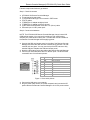
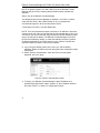
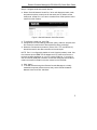
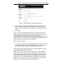
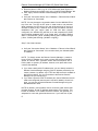
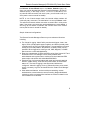
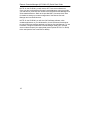
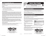
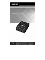
LES1204A-3G
Remote Console Manager
Quick Start Guide
This Quick Start Guide helps you through installation, configuration,
and local operation. For more details, refer to the user manual
on CD-ROM.
Remote Console Manager (LE1204A-3G) Quick Start Guide
Trademarks Used in this Manual
Black Box and the Double Diamond logo are registered trademarks of
BB Technologies, Inc.
Cisco is a registered trademark of Cisco Technology, Inc.
Linux is a registered trademark of Linus Torvalds.
Nagios is a registered trademark of Nagios Enterprises.
Any other trademarks mentioned in this manual are acknowledged to be the
property of the trademark owners.
2
Remote Console Manager (LES1204A-3G) Quick Start Guide
Follow the steps listed below to get started:
Step 1: Check kit contents.
LES1204A-3G Remote Console Manager
This printed quick start guide
(1) CD-ROM containing a user’s manual in PDF format
(2) UTP cables
(1) DB9F-RJ-45 adapter straight-pinned
(1) DB9F-RJ-45 adapter crossover-pinned
(1) RF antenna with bracket mount and 1-ft. (30-cm) cable
Universal input 12-VDC power pack
Step 2: Connect the hardware.
NOTE: The LES1204A-3G Remote Console Manager has an internal 3G
GSM cellular modem. Your carrier will provide you with a SIM card to
activate your GSM cellular modem plan. The SIM card must be installed in
the Remote Console Manager before applying power.
Unscrew the SIM card access panel on the side of the Remote Console
Manager and insert the SIM card with contacts facing upward. The SIM
card will lock into place. You may use the tip of the RF antenna to fully
seat the SIM card. Replace the SIM card access panel.
Attach the RF antenna using the cable to the Remote Console Manager.
Connect your serial devices to the four SERIAL ports. The RJ-45 serial
connectors have Cisco® serial pinouts:
!
"
#
$
Figure 1. Cisco serial pinouts.
Connect the LAN port to your network.
Plug the power pack into the AC power receptacle and connect the DC
power cable to the Remote Console Manager’s 9-12 VDC power socket.
3
Remote Console Manager (LE1204A-3G) Quick Start Guide
NOTE: On applying power, the “SIM” LED on top of the Remote Console
Manager will go on solid, indicating that the SIM has been inserted and
detected.
Step 3: Set up the Remote Console Manager.
The default Remote Console Manager IP address is 192.168.0.1 (subnet
mask 255.255.255.0). With a Web browser on any computer that is
connected through the LAN to the serial device server:
• Enter https://192.168.0.1 into the address bar.
NOTE: The LAN-connected computer must have an IP address in the same
network range (192.168.0.xxx) as the Remote Console Manager. If this is not
convenient, you can use the ARP Ping command to set the IP address (refer
to the user manual for details). The Remote Console Manager also has its
DHCP client enabled by default, so it will automatically accept any network
IP address assigned by any DHCP server on your network—and will then
respond at both 192.168.0.1 and its DHCP address.
Log in using the default system user name: root, and the default
password: default. A Welcome screen listing the basic configuration steps
is displayed.
Select “System: Administration,” enter and confirm a new system
password, and click “Apply.”
Figure 2. System: Administration screen.
4
To assign your Remote Console Manager a static IP address or to
permanently enable DHCP, select “System: IP” then “Network Interface”
and check “DHCP” or “Static” for configuration method.
Remote Console Manager (LES1204A-3G) Quick Start Guide
Step 4: Configure serial and network devices.
Select “Serial & Network: Serial Port,” which will display the label, mode,
and protocol options currently set for the serial port. By default, all the
serial ports, except Port 1, are set to console server mode (see the user‘s
manual for other modes).
Figure 3. Serial & Network: Serial Port screen.
To configure a serial port, click “Edit.”
Configure the common settings (baud rate, parity, data bits, stop bits, and
flow control) to match those of the serial device being controlled.
Select the console server protocols (Telnet, SSH, TCP, and RFC2217)
that will be used for the data connection to the serial port.
NOTE: Port 1 is configured by default in Local Console (modem) mode. Use
the crossover-pinned DB9F-RJ-45 adapter and UTP cable to connect to a
terminal emulator application on your PC’s serial COM port. If you plan to
use out-of-band (OoB) dial-in access, connect this serial port to an external
modem as covered in detail in the user manual on the CD-ROM.
Click “Apply.”
To enable access through the Remote Console Manager to a locally
networked computer (referred to as a host), select “Serial & Network:
Network Hosts” and click “Add Host.”
5
Remote Console Manager (LE1204A-3G) Quick Start Guide
Figure 4. Serial & Network: Network Hosts screen.
Enter the IP address/DNS name of the host.
Edit the permitted services used for accessing this host, for example,
HTTPS (TCP port 443), VNC (TCP port 5900), or add custom TCP or
UDP port numbers—only the services specified here are tunneled
through to the host. All other services are blocked.
Specify the level of information to be logged and monitored for each host
access.
Click “Apply.”
Step 5: Add new users.
NOTE: We recommend that you set up a new Administrator user (in the
admin group with full access privileges) and log in as this new user for all
ongoing administration functions (rather than continuing as root).
For each new user, select “Serial & Network: Users & Groups” and click
“Add User.”
Enter a username and enter and confirm a password, and nominate the
accessible hosts and accessible ports the user is allowed to access.
6
Remote Console Manager (LES1204A-3G) Quick Start Guide
Figure 5. Serial & Network: Users & Groups screen.
To grant limited access to the management console, check the “User”
group. To grant full access to the management console, check the
“Admin” group. By default, the user is granted no management console
access.
Click “Apply.”
Note: The Remote Console Manager comes with a default certificate for
initial configuration purposes only. You will need to direct your browser to
(temporarily) proceed and accept this untrusted certificate. It is
recommended as soon as possible thereafter you generate and install a new
trusted certificate. To produce the unique CSR and later upload the newly
issued certificate, select System: SSL Certificates.
Step 6: Connect to Carrier.
To configure the Remote Console Manager cellular modem to connect to
your carrier, select the “Internal Cellular Modem” tab on the “System:
Dial” menu and check “Enable” for “Dial-Out Settings—OOB.”
NOTE: With OOB (Out-Of-Band) enabled, the cellular modem connection
once established will remain always ON.
NOTE: Your GSM carrier may have provided you with details for
configuring the connection including APN (Access Point Name), Pin
Code (optional PIN code which may be required to unlock the SIM
card), Phone Number (the sequence to dial to establish the connection,
defaults to *99***1#), Username/Password (optional) and Dial string
(optional AT commands). However, you generally will only need to
enter your carrier’s APN and leave the other fields blank.
7
Remote Console Manager (LE1204A-3G) Quick Start Guide
Enter the carrier’s “APN” (e.g. for AT&T USA simply enter i2gold; for TMobile USA enter epc.tmobile.com) on the “Internal Cellular Modem” tab.
Click “Apply” and the Remote Console Manager will connect to the
carrier.
Verify the “Connection Status” in the “Statistics— Failover& Out-of-Band”
tab is shown as “Connected.”
NOTE: You can also see the connection status from the WWAN LED on
top of the unit. The LED is OFF when in reset mode or not powered.
When powered, the LED will go ON, and while searching for service it
will flash off briefly every 5 seconds. Once a radio connection has been
established with your carrier (after an APN has been properly
configured), the WWAN LED will blink at a rate proportional to traffic
signal strength detected (OFF =Low, [lower than -100 dBm], Blinking
Slow = Low to Medium [-99 to -90 dBm], Blinking Fast = Medium to High
[-89 to -70 dBm] and ON=High [-69 dBm or higher]).
Step 7: Out of band access
Verify the “Connection Status” in the “Statistics—Failover & Out-of-Band”
tab is shown as “Connected.” You can also check your allocated public
“IP Address.”
NOTE: To directly access the Remote Console Manager, it needs to
have a Public IP address and it must not have SSH access firewalled.
Almost all carriers offer corporate mobile data service/plans with a
Public (static or dynamic) IP address; however, such plans often have
a service fee attached.
If you have a static public IP address plan, you can directly access the
Remote Console Manager using the public IP Address provided by the
carrier. However, by default, only HTTPS and SSH access is enabled on
the OOB connection. So, you can browse to the Remote Console
Manager, but you cannot ping it.
If you have a dynamic Public IP address plan, then a DDNS service will
need to be configured (see the user’s manual for details). Once this is
done, you can then access the Remote Console Manager using the
allocated domain name.
NOTE: By default, most providers offer a consumer grade service that
provides dynamic Private IP address assignments to 3G devices. This
Private IP address is not visible across the Internet, but generally it is
adequate for home and general business use. If you have such a plan,
8
Remote Console Manager (LES1204A-3G) Quick Start Guide
the Failover & Out-of-Band tab on the Status: Statistics page, will
show your carrier allocated the Remote Console Manager a Private IP
Address (that is, in the range 10.0.x.x, 172.16.x.x or 192.168.x.x). For
an inbound OOB connection with such a plan, you will need to set up a
VPN (see the user‘s manual for details).
NOTE: In out of band access mode, the internal cellular modem will
continually stay connected. The alternative is to set up Failover mode.
This will tell the internal cellular connection to remain idle in a low power
state. If the primary and secondary probe addresses are not available, it
will bring up the cellular connection and connect back to the cellular
carrier (see the user’s manual for details).
Step 8: Advanced configurations.
The Remote Console Manager offers many more advanced functions
including:
The “Alerts & Logging: Alerts” facility monitors serial ports, hosts, user
logins, UPSs (uninterruptible power supplies), and RPCs (remote power
controllers such as PDUs and IPMI devices). A broad selection of trigger
events (such as data patterns, temperature, or battery levels) can be
specified. When triggered, a warning e-mail, SMS, Nagios®, or SNMP
alert is sent to a nominated destination.
Extensive management of UPSs and RPCs using Open Source NUT and
Powerman tools. The “Manage: Power” facility enables both
administrators and regular users to monitor and control attached PDU
power strips, and servers with embedded IPMI BMCs.
Historical logs of all communications with serial and network-attached
devices, system activity, UPS and PDU power status, environmental
status, etc. The level of logging is set as ports and devices are
configured. “Alerts & Logging: Port Log” allows this history to be saved
locally or remotely. Logs can be viewed from the “Status” and “Manage”
menus.
Other advanced features, such as serial port cascading, remote
authentication, trusted networks, secure tunneling, Nagios distributed
monitoring, and the command line interface are covered in detail in the
user manual on the CD-ROM.
9
Remote Console Manager (LE1204A-3G) Quick Start Guide
NOTE: On the CD-ROM, you will find the SDT Connector software tool.
Once you have configured the Remote Console Manager, this tool provides
you with secure, point-and-click access to the Remote Console Manager and
all the attached devices. Refer to the provided SDT Connector Quick Start
for details on setting up remote management of the Remote Console
Manager and connected devices.
NOTE: On the CD-ROM, you will also find PortShare software, which
enables applications on your Windows® or Linux® PC/server/virtual server
to control serial port devices attached to a Remote Console Manager. To use
PortShare, configure the Remote Console Manager serial port in console
server mode and specify the appropriate protocol (either RFC2117 or RAW)
to be used (see the user’s manual for details).
10
Remote Console Manager (LES1204A-3G) Quick Start Guide
11
LES1204A-3G QSG, rev. 2