1
Instruction Manual
CS-200 Series
1
Table of Contents
Table of Contents .................................................................................................................................. 2
Introductions......................................................................................................................................... 3
Features ................................................................................................................................................ 4
Safety Instructions ............................................................................................................................... 5
Installations & Connections ................................................................................................................. 6
1.
Connection between Conference Main control unit & Chairman/Delegate MIC. ...................... 6
2.
Connection between Main control unit & High speed dome Positioning System ...................... 7
3.
Basic Connection between Conference Main control unit & Software Control System ............. 8
CS-200 Operation & Function Instructions ......................................................................................... 9
1.
Main control unit’s Front/Rear Panel Functions Instructions .................................................... 9
1.1 【Front Panel】 ................................................................................................................. 9
1.2 【Rear Panel】................................................................................................................ 10
2.
Power On .............................................................................................................................. 11
3.
LCD Instructions .................................................................................................................... 12
4.
System’s Operations & Settings ............................................................................................ 13
4.1 Using MIC. ID Checking ................................................................................................... 13
4.2 Conference Mode Settings ............................................................................................... 14
4.3 Settings of the limiting number of simultaneously usable delegate microphone ................ 16
4.4 Time Settings (Automatic Mic Off) ..................................................................................... 16
4.5【Save】Settings .............................................................................................................. 17
4.6 Speed Dome Camera Settings ......................................................................................... 17
4.7 Speed Dome Camera Mode Settings ................................................................................ 20
4.8 Mic Checking Mode Settings ............................................................................................ 20
4.9. Speed Done Return ......................................................................................................... 22
4.10. Video Auto Switch .......................................................................................................... 23
4.12 Volume Mode Settings ........................................................................................................... 24
4.13 MIC Volume Mode Settings ............................................................................................ 24
4.14 AUX Volume Mode Settings ............................................................................................ 24
Table-Top Delegate Mic cs-200DU Unit ......................................................................................... 25
Table-Top Delegate Mic- CS-200DU Unit ....................................................................................... 28
Table-Top Chairman Mic- CS-200CU Unit .................................................................................... 31
Table-Top Delegate Mic- FCS 3112/3116 Unit .............................................................................. 33
Appendix. Speed Dome Basic Setting .............................................................................................. 35
1.1 Power On & Off........................................................................................................................ 35
1.2 Telecom On& Off ..................................................................................................................... 35
1.3 IP Address ............................................................................................................................... 36
2.1 Telecom Protocol ..................................................................................................................... 37
2.2 Definition of Data Transmission Cord ....................................................................................... 37
2
Introductions
This CS-200 series, the latest state of the art digital conference control system with superb performance
and elegant design, can be used for various conferencing.
This conference system has the most advanced built-in digital control mode with 10 chairman
microphones and 999 delegate microphones (the number of microphones used depend on actual
requirement). The unique features are as follows:
Sound Effect Processing Amplified Mode
Fast speed dome Positioning Control Mode
Graphic Control Software Communication Mode
Above features are capable of meeting your demands under any circumstance.
With high-speed 360° endless rotation and auto-returning functions enable High speed dome being
applied in various difficult and multi-spot image positioning. RS-485 communication interface provides
remote control. 128 programmable preset positions can be precisely located with the target position.
Also dome IP speed dome has automatic surveillance functions for different paths defined by you.
With its unique “Self-Detecting” function, when the power is on, the system will be executed automatic
detection of all chairman/delegate units whether it’s normal or not. Therefore, you could judge the
system whether it’s normal timely.
Higher reliability is the utmost importance factor in the process of R&D of this conference system. Each
conference unit and its related products are through careful assembly and strict test in our ISO 9001
factory.
With the excellent performance, “High reliability” and “Reasonable price” make it indispensable tools of
your conferencing.
3
Features
Main control unit of the Conference System
1. Digital Control Capability: Chairman’s Unit x10, Delegate’s Unit x 999
2. ID Settings of the Conference Unit: 10-Bit Dip Switch Adopted.
3. Numbers Ranged From 001 ~ 999, Totally 999 Delegate Units.
4. ID Position Code of Delegate Unit: 001~999, Totally 999 Codes.
5. ID Position Code of Chairman Unit: *01~ *10, Totally 10 Codes.
6. 1x LCD (20*4) And 5 X LED Setting Buttons: MODE, UP, DN, STEP and SAVE which control MIC
Mode and the Volume of the Conference.
7. Built-in digital volume control mode
8. Built-in auto-image tracing & positioning control mode.
9. Built-In Software Control Communication Interface.
10.Built-in front sound mixing amplifier mode.
11.Built-in high pressure signal transfer mode
Chairman Unit
1. Table-top and Flush-mounted types
2. Equipped TALK and Control buttons(functions are as same as the control buttons on the main control
unit).
3. Equipped with the digital volume control mode for adjusting the volume of the conference
4. Equipped with LCD(24*2) mode (Only for CS-200DU/CU )
5. It can be plugged at any position in the system.
6. Maximum microphones: 10 units
Delegate Unit
1. Desktop, Built-In and Hand-Held Types.
2. Equipped with TALK/Request button.
3. Equipped With LCD(24*2) Mode (Only for CS-200DU/CU)
4. Maximum MIC: 999 units
4
Safety Instructions
1. Please read and observe these instructions before installing and using the apparatus.
2. Use only accessories specified by the manufacturer. The manufacturer is not liable for damage
caused by the use of non-specified accessories.
3. Install the apparatus and its accessories carefully. Strike and fierce shaking may damage the
apparatus.
4. Make sure the power cord is fixed properly.
5. Do not overload wall outlets and extension cords as this can result in a risk of fire or short circuit.
6. To reduce the risk of damage from lightning strikes, it is important that all electric cables should
be bonded to the same grounding point.
7. Do not block any ventilation openings to prevent overheating and malfunction.
8. Do not expose the apparatus to rain or moisture.
Humidity may lead inside components to damage. Appropriate shelter is necessary when placing
it outside (Best working environment: Temperature 0°C ~ 40°C <32°F ~ 104°F>, humidity below
90%).
9. Please do not switch on and off the apparatus rapidly.
Rapid switch on and off the apparatus should be avoided all the time to prevent inside sensitive
electronic circuits from being damaged by surges.
10. Do not clean the apparatus and its accessories with chemical solvents. Use only a clean,
dry/dampish cloth.
11. Refer to maintenance technician when the apparatus has been damaged in any way, such as:
A• power-supply cord or plug is damaged
B• liquid has been spilled in
C• has been exposed to rain or moisture
D• has been dropped
E• objects have fallen into the apparatus
F• does not operate normally
12. Note: When the printed circuit board is going through electric static treatment, correct ESD
safety precaution and grounding should be assured.
13. Note: Before connecting the apparatus to main AC, please select the supply voltage in
accordance with the wall voltage in your country to prevent damage. Refer to Installation and
Setting (Page 8) for selecting.
14. Warning: Do not disassemble or remodel the product, as these actions may lead to electrical
shock or damage. The guarantee on the product will become null if the product is ever
disassembled.
5
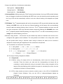
Installations & Connections
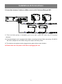
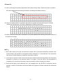
1.Connection between Conference Main control unit & Chairman/Delegate MIC.
BXB
BXB
!
CAUTION
RISK OF ELECTRIC SHOCK
DO NOT OPEN
CAUTION:
.TO PREVENT ELECTRIC SHOCK
DO NOT REMOVE COVER(OR BACK)
.NO USER SERVICEABLE PARTS
TO QUALIFIED SERVICE PERSONNEL
~ AC FUSE 250V T8A
MADE IN TAIWAN
http://www.bxb.com.tw
IOIOI
DC FUSE
D+ D-
1
10
L.Spearer
Aux Output
Conference Link
Aux Input
Mic Input
SpeedDome
BXB
BXB
TOP
1.1 There are three groups of microphone port on the main control unit, which can be connected
randomly.
1.2 Chairman/delegate unit is equipped with hidden connecting terminal. While connecting, CS-200YC
fast cord is adopted to form hidden wiring with simple and beauty effect.
1.3 The chairman microphone can be plugged at any place without order limitation.
1.4 Please make sure the power is off before unplugging the unit.
6
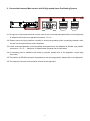
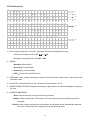
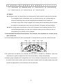
2. Connection between Main control unit & High speed dome Positioning System
2P Â ù
µ ±
½u
16 PCS
D+ D-
D+ D-
!
D+ D-
FCS 3150/6150
卡訊電子實業有限公司
CAUTION
RISK OF ELECTRIC SHOCK
DO NOT OPEN
CAUTION:
.TO PREVENT ELECTRIC SHOCK
DO NOT REMOVE COVER(OR BACK)
.NO USER SERVICEABLE PARTS
TO QUALIFIED SERVICE PERSONNEL
~ AC FUSE 250V T8A
MADE IN TAIWAN
http://www.bxb.com.tw
IOIOI
DC FUSE
D+ D-
1
10
L.Spearer
Conference Link
Aux Output
Aux Input
Mic Input
SpeedDome
D+ D-
Äá
¼v
¾÷
± ±
¨ îÁ ä
½L
§ Ö
³ t° j à
Äá
¼v
¾÷
§ Ö
³ t° j à
Äá
¼v
¾÷
2.1 One group of fast socket terminal on main control unit connected with speed dome control keyboard
is adopted with Double core parallel connection(D+, D-).
2.2 Please ensure the plug position correctly to avoid mal-operating while connecting between main
control unit and speed dome control keyboard.
2.3 Cords connected between control keyboard and speed dome are adopted as Double core parallel
connection(D+, D-). Maximum 16 speed dome cameras can be connected.
2.4 If connecting cord is needed to be made by yourself, please refer to the Appendix- control plug
instruction.
2.5 The position of RS-485 connector of speed dome can the plug position, please refer to the Appendix.
2.6 The material of control cords could be referred to the Appendix.
7
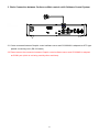
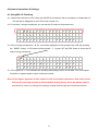
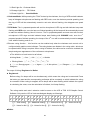
3. Basic Connection between Conference Main control unit & Software Control System
!
CAUTION
RISK OF ELECTRIC SHOCK
DO NOT OPEN
CAUTION:
.TO PREVENT ELECTRIC SHOCK
DO NOT REMOVE COVER(OR BACK)
.NO USER SERVICEABLE PARTS
TO QUALIFIED SERVICE PERSONNEL
~ AC FUSE 250V T8A
MADE IN TAIWAN
http://www.bxb.com.tw
IOIOI
DC FUSE
D+ D-
1
10
L.Spearer
Conference Link
Aux Output
Aux Input
Mic Input
SpeedDome
FCS 3150/6150
3.1 Cords connected between Graphic control software server and CS-200 MU is adopted as 9P D type
parallel connecting cord. (RS-232 cable)
3.2 Please ensure the connection between Graphic control software server and CS-200MU is adopted
as COM1 port (which is not being used by other machines).
8
CS-200 Operation & Function Instructions
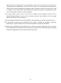
1.Main control unit’s Front/Rear Panel Functions Instructions
1.1 【Front Panel】
5
6
ConferenceSystem Control Unit
-8
Mic
Mode
Up
Down
Step
Up
Save
4
3
Aux
Down
Up
-5
-2
0
+2
Power
Down
1
2
1. POWER: power switch。
2. AUX volume control: Adjust the volume of the equipment connected to the AUX input jack
3. MIC volume control: Adjust the volume of the microphone connected to the microphone input jack
4. Conference function control :
MODE: Mode-changing
UP: step up of parameter change /volume up
DN: step down of parameter change /volume down
STEP: selecting parameter setting of the IP speed dome from left to right.
SAVE: save the settings.
5. Volume output LED indicator lamp.
6. LCD(20×4)
9
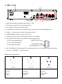
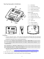
1.2 【Rear Panel】
9
8
!
CAUTION
RISK OF ELECTRIC SHOCK
DO NOT OPEN
CAUTION:
.TO PREVENT ELECTRIC SHOCK
DO NOT REMOVE COVER(OR BACK)
.NO USER SERVICEABLE PARTS
TO QUALIFIED SERVICE PERSONNEL
~ AC FUSE 250V T8A
MADE IN TAIWAN
http://www.bxb.com.tw
IOIOI
DC FUSE
D+ D-
1
10
L.Spearer
Aux Output
Conference Link
Aux Input
Mic Input
SpeedDome
7
6
5
4
3
2
1
1. MIC Input: dynamic microphone input terminal(XLR)
。
2. AUX Input: external sound input terminal (XLR)。
3. AUX Output: sound output terminal (XLR)。
4. L. Speaker-VR: master volume-control of built-in loud speaker of chairmen/delegate unit.
5. LINK 1 ~ 3: Connect to conference microphone unit port.
6. SPEED DOME connection: control port. (D+, D-)
7. Conference main control unit DC power fuse seat(DC 250V/8A).
8. PC DATA: RS-232 control port to Graphic control software server.
2nd foot: Transmitted Data (Tx)
3rd foot: Received Data (Rx)
5th foot: Signal Ground(G)
9. AC 110V/220V inlet. Equipped with AC overload protection fuse, one protection fuse and one stand
by fuse(AC 250A/8A )under the socket.
※Audio input/ output feet info
1:Ground
1:Ground
1:Ground
2:Hot(+)
2:Sigal(Aux)
2:Sound(Aux)
3:Cold(-)
3:Empty
3:Empty
10
2.Power On
2.1 After confirming all the above adjustments and control wiring is done. Switch the power on and the
LCD will be displayed the following information (including the software version)::
B X B
1 . 7 0
C o n f e r e n c e
V e r s i o n
P A
S y s t e m
2.2 Later, the system will be in connection test mode, the system will start scanning all connected
conference microphones; LCD will be displayed the following information:
M e m o r
· · ·
y
C h e c k
· · · O K
2.3 When connection test mode is completed, LCD will be displayed the following information and turn to
the preset menu page.
1
2
3
4
N
M
O
A
O
O
P
U
:
D E :
N o r m a l
E N - M I C :
0 2
T O - O F F :
3 0
M i c
S e c
NOTE:
1. When main control unit is ON, this conference system will be executed microphone connection test.
At this moment, the red LED of microphone will be constantly on; 5 seconds later, if the connection
was wrong, it will be flashing. It means the connection is failure.
2. In this case, the power of main control unit should be switched off and check whether the microphone
connection is correct or not and then switch it on again. If the red LED of the microphone is
constantly on for more than 5 seconds, and the connection of the microphone is normal.
3. Press the talk button of the chairman unit or any delegate unit, the red LED of microphone can be
cleared, or wait for 30 seconds until the test mode of the system is finished, and then the conference
begins.
11
3.LCD Instructions
1
2
3
4
N
M
O
A
O
O
P
U
:
D E :
N o r m a l
E N - M I C :
0 2
T O - O F F :
3 0
5
S P E E D
M I C
( 0 0 1 )
6
S P E E D
( N o n e )
○,1
○,21
○,
M i c
S e c
D O M E
S E T T I N G
D O M E
0 1
A D R
0 0 1
D O M E
B u
t
M O D E
t o n
V o
i
○,3
○,4
○,5
○,6
c e
1. NO: Using microphone’s ”ID code”: 3 groups of ID code are displayed per page.
i. Chairman microphone’s”ID code”:1 ~ 10
ii. Delegate microphone’s”ID code”:001 ~ 999
2. MODE:
i. Normal:Normal Mode
ii. Override:Override Mode
iii. Chairman:Chairman Mode
iv. FIFO:First in first out (FIFO) mode
3. OPEN-MIC: three modes of limiting the number of simultaneously usable units: 1~30, all open and
chairman mode.
4. AUTO-OFF (Automatic Mic-off): 10 ~ 99 second & and manual turn off.
5. SPEED DOME SETTING: Displays and settings of Speed Dome & chairman/delegate microphone.
ID code
6. SPEED DOME MODE:
i. None: Stop Auto-Image Tracing & Positioning function
ii. Button: When pressing the “Talk” button, the auto image tracing and positioning mode is
activated.
iii. Voice: When using more than two microphones, speed dome will be automatically detected
the voice for executing auto image tracing and positioning mode.
12
4.System’s Operations & Settings
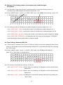
4.1 Using MIC. ID Checking
4.1.1 When the conference unit is using, the red LED of microphone will be constantly on. Meanwhile, its
ID code will be displayed on the LCD of main control unit.
4.1.2 Less than 3 using microphones, you can see the ID code on the preset menu.
1
2
3
4
N
M
O
A
O
O
P
U
:
0 0
D E :
E N - M
T O - O
1
0 0 2
0 0 3
N o r m a l
I C :
0 2
M i c
F F :
3 0
S e c
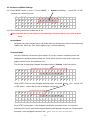
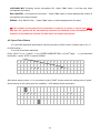
4.1.3 Over 3 using microphones,” ” icon will be displayed on the up-right of the LCD. By pressing
the ” MODE “ button LCD screen will be showed ” ◘” press “UP” and ”DN” button to check the ID
code of using microphone.
1 ◘ N O :
0 0
2
M O D E :
3
O P E N - M
4
A U T O - O
1
0 0 2
0 0 3
N o r m a l
I C :
0 2
M i c
F F :
3 0
S e c
4.1.4 The symbol of” ◘” icon indicates the operating and setting function is activated. You could repeat
this action to operate and set up all conference modes.
Note: All the figures appeared on this manual is only for samples explanation. Each main control
unit has been through a series of QC test before leaving factory. Since the default value is
not identical, users can change the settings simply followed by the instruction manual.
13
4.2 Conference Mode Settings
4.2.1 Press”MODE” button move” ◘” icon to MODE
Normal (is flashing) press”UP” or ”DN”
change the conference mode.
1
N O
2 ◘ M O
3
O P
4
A U
:
0 0
D E :
E N - M
T O - O
1
0 0 2
0 0 3
N o r m a l
I C :
0 2
M i c
F F :
3 0
S e c
4.2.2 The following conference modes can be set.
※The chairman, who is not subject to the following conference mode, can speak anytime
freely.
Normal Mode:
Delegates can press the talk button and speak within the limiting the number of simultaneously
usable units. Press the “Talk” button again to turn it off after speaking.
Chairman Mode:
Only the Chairman unit has the right to speak. Of course, chairman could also permit the
delegates unit speaking while pushing the “TALK” button by three ways (main control unit,
graphic control server and Chairman unit).
The ID code of requesting Delegate microphone will be ”flashing” in the first column.
1 ◘ N O :
可
2
M O D E
3
O P E N
4
A U T O
0 0 1
0 0 2
0 0 3
:
C h a i r m a n
- M I C :
0 2
M i c
- O F F :
3 0
S e c
Press ”STEP” button to enter delegate-selecting mode. You’ll see (×××) icon. press ”UP”
or ”DN” button select the ID code of delegate microphone.
1 ◘ N O :
2
M O D
3
O P E
4
A U T
(
E
N
O
0 0 1 ) 0 0 2
0 0 3
:
C h a i r m a n
- M I C :
0 2
M i c
- O F F :
3 0
S e c
Press”STEP” button again the delegate microphone is allowed to talk. You’ll see the
selecting unit of its ID code will be stopped flashing and delegate can talk now. Please repeat
this steps if more delegates request to talk. (this step can also be executed
14
simultaneously by pressing the 5 multi-function buttons of chairman unit).
When the numbers of speaker and requesting speakers are over three, you will see this arrow
icons →、←、↔ displayed on LCD of Chairman unit and main unit, indicating →(next page)、
←(last page)
、↔(continued last and next pages).
1 ◘ N O :
2
M O D
3
O P E
4
A U T
(
E
N
O
0 0 1 ) 0 0 2
0 0 3
:
C h a i r m a n
- M I C :
0 2
M i c
- O F F :
3 0
S e c
→
Override Mode:
Example 1: If you limit the number of simultaneously usable delegate microphone as 1, while the
“TALK” button of the 2nd delegate unit has been pressed, the last using microphone will be
switched off automatically.
Example 2: If you limit the number of simultaneously usable delegate microphone as 3, while the
“TALK” button of the 4th (5th) delegate unit is been pressed, the 1st (2nd) delegate unit will be
switched off. It will be always limited 3 simultaneously usable delegate microphones. Therefore,
you can follow the same rule to set up if the numbers of simultaneously usable delegate
microphone ranged from 1~30.
※The chairman, who is not subject to the conference mode, can speak anytime freely.
FIFO Mode:
If the limiting numbers of simultaneously usable delegate microphone are 1, while the “TALK”
button of the 2nd delegate unit, the prepared speaker, is been pressed, its indicator lamp & ring
of light are flashing with red color; as for the 3rd delegate unit or more units, theirs “TALK”
button LED are flashing with orange color.; When the 1st delegate finishes speaking, the 2nd one
will be automatically switched on, and the 3rd one will become the prepared speaker. The
chairman microphone is not restricted to this and can speak freely.
1 ◘ N O :
0 0
2
M O D E :
3
O P E N - M
4
A U T O - O
1
F I
I C
F F
0 0 2
0 0 3
F O
:
0 2
M i c
:
3 0
S e c
At this time, chairman mode operation can still be applied to select prioritized speaker by overriding
the FIFO mode.
15
4.3 Settings of the limiting number of simultaneously usable delegate
microphone
4.3.1 You can select “Open- Mic: ALL Mic” mode (see below ) or set up the limiting number of
simultaneously usable delegate microphone ranged from 1~30.
4.3.2 Press ”MODE” button move” ◘” to OPEN –MIC mode No. 03 Mic will be flashing press ”UP”
or ”DN” button again change the No.
1
N
2
M
3 ◘ O
4
A
O
O
P
U
:
0 0
D E :
E N - M
T O - O
1
0 0 2
0 0 3
N o r m a l
I C :
0 3
M i c
F F :
3 0
S e c
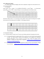
4.3.3 The limiting number of simultaneously usable delegate microphone ranged from 1~30.
4.3.3.1 OPEN –MIC:1 Mic limiting the number of simultaneously usable delegate unit: 1
4.3.3.2 OPEN –MIC:30 Mic limiting the number of simultaneously usable delegate unit: 30
4.3.3.3 OPEN –MIC:ALL Mic limiting the number of simultaneously usable delegate unit: None
4.3.3.4 OPEN –MIC:REQUEST In Chairman mode, this column will be displayed ” REQUEST, ”
meaning delegates need to press button to request to speak.
4.4 Time Settings (Automatic Mic Off)
4.4.1 The function of automatic mic off (from 10~99 sec) could be set up after speaking finished, when
times up, the delegate unit will be automatically switched off or be manually switched off by pressing
the “TALK” button.
4.4.2 Press ”MODE” button move “◘” to AUTO –OFF mode No. 30 Sec will be flashing
press ”UP” or ”DN” button change the No.
1
2
3
4 ◘
N
M
O
A
O
O
P
U
:
0 0
D E :
E N - M
T O - O
1
0 0 2
0 0 3
N o r m a l
I C :
0 3
M i c
F F :
3 0
S e c
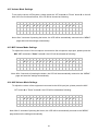
4.4.3 The function of automatic mic off (from 10~99 sec).
4.4.3.1 AUTO –OFF:10 Sec 10 sec later if not speaking, the delegate unit will be automatically
switched off.
4.4.3.2 AUTO –OFF:99 Sec 99 sec later if not speaking, the delegate unit will be automatically
switched off.
4.4.3.3 AUTO –OFF:Invalid the delegate unit should be manually switched off by pressing the
“TALK” button
16
4.5【Save】Settings
4.5.1 When all above settings finished, if you want to save them as default value, you only need to push
“SAVE” button. When it’s done, the saved setting is permanent. Power failures of switching off do
not clear the default value.
4.5.2 When “SAVE” button is pressed, the LCD will be displayed in the following information.
S a v e .
.
.
.
.
.
.
.
. O K
4.6 Speed Dome Camera Settings
4.6.1 Each Speed Dome has the function of Auto-Image Tracing & Positioning which can be set up from
the main control unit. Each chairman/delegate unit could set up to16 Speed Domes which has 128
Programmable Preset Positions of each camera.
4.6.2 Press ”MODE” button move “◘” to SPEED DOME SETTING mode(the 2nd page of the MENU)
()ID code 001 displayed under MIC column press ”UP” or ”DN” button select the “ID code”
of microphone
5 ◘ S P E E D
D O M E
S E T T I N G
M I C
( 0 0 1 )
D O M E
0 1
A D R
0 0 1
4.6.3 The conference system totally has 1,009 groups of ID codes.
4.6.3.1 ID code of delegate unit: 999 groups of numbers from 001 ~ 999
4.6.3.2 ID code of chairman unit: 10 groups of numbers from 1 ~ 10
4.6.4 When “ID code” of microphone has been selected press ”STEP” button move to right side to
ID code 001 under DOME column ()ID code 01 displayed under DOME column press ”UP”
or ”DN” button select the “ID code” of IP Speed Dome (See the Appendix – ID Codes of Speed
Dome camera)
5 ◘ S P E E D
D O M E
S E T T I N G
M I C
0 0 1
D O M E
( 0 1 )
A D R
0 0 1
4.6.5 One main control unit can control 16 speed domes cameras. No. 01 ~ 16 is the” ID code” of these
16 speed dome cameras.
4.6.6 When “ID code” of speed dome has been selected press ”STEP” button move to right side to
ID code 001 under ADR column ()ID code 01 displayed under ADR column press ”UP”
or ”DN” button select the “Programmable Preset Positions” of Speed Dome.
17
5 ◘ S P E E D
D O M E
S E T T I N G
M I C
0 0 1
D O M E
0 1
A D R
( 0 0 1 )
4.6.7 Each speed dome has 128 Programmable Preset Positions.
4.6.7.1 When the figure under ADR column displayed 001, it is the 1st Programmable Preset
Positions.
4.6.7.2 When the figure under ADR column displayed OFF, the function of Auto-Image Tracing &
Positioning is disabled.
4.6.8 When above three steps finished setting press ”SAVE ” button to save the setting value of the
speed dome camera When “SAVE” button is pressed, the LCD will be displayed in the following
information.
S a v e .
.
.
.
.
.
.
.
. O K
4.6.9 Now, the picture in LCD will be back to item 4.6.2. Repeat the above setting steps for other
conference unit.
4.6.10 The Programmable Preset Position is the 128th of ID address and the 1st ID code of the IP speed
dome. It is mainly used to turn the IP speed dome automatically to the 128th conference preset
position when there is no using microphone.
18
4.6.11 Auto-return (HGO)
After setting, the camera will shoot the preset point (the whole meeting area or at the chairman) when
none microphone is in use.
Press "MODE" button switch "◘" to SPEED DOME SETTING (the second page) ( ) will be shown
below MIC press "UP" or "DN" button and select HGO select camera number under DOME
select camera position under ADR.
5
◘
S P E E D
D O M E
S E T T I N G
M I C
H G O
D O M E
( 0 1 )
A D R
0 0 1
(The position of Auto-return {HGO} can be set at any {ADR} of any {DOME}).
After above setting is done it is a must-do to press ”SAVE ” button to save the setting value of speed
dome camera (or the setting won’t be modified) LCD displays follow information.
S a v e .
.
.
.
.
19
.
.
.
. O K
4.7 Speed Dome Camera Mode Settings
4.7.1 Auto-Image Tracing & Positioning Control Mode
4.7.1.1” None” mode: Auto-Image Tracing & positioning is disabled.
4.7.1.2” Button” mode: The speed dome will be tracing & positioning the image while the “TALK”
button is being pressed. The images of Speed Dome will be positioned to the last talking
microphone. By pressing the “TALK” button, the chairman or delegates could have the images
of positioned again
4.7.1.3 ”Voice” mode: The speed dome will not only be tracing & positioning the image while the
“TALK” button is being pressed for the first time but also it will be tracing & positioning the
image automatically where the voice coming from.
4.7.2 How to Operate:
4.7.2.1 Press ”MODE” button move ” ◘ ” to SPEED DOME MODE(the 3rd of the MENU) the
previous settings will be displayed on the LCD press ”STEP” button select mode Save
6 ◘ S P E E D
( N o n e )
D O M E
B u
t
M O D E
t o n
V o
i
c e
4.8 Mic Checking Mode Settings
4.8.1 After the installation is completed, you have to execute the “Scan” functions first, and then the
system will be automatically scanned and detected all the microphones. The numbers of
microphones and their ID codes will be recorded in the system. Now, the first self-detecting action
is completed.
4.8.2 How to Operate:
4.8.2.1 Press ”MODE” button move ” ◘ ” to 7. MIC CHECKING MODE(the 4th page of the
MENU) It will be showed as following:
7 ◘ M I C
C H E C K I N G
( T e s
t
)
M O D E
S c a n
20
Press ”STEP” button move()to “Scan” press ”SAVE” button.
7 ◘ M I C
C H E C K I N G
T e s
t
M O D E
( S c a n )
The following display will be lasted about 30 sec.
E R A S E
M E M O R Y
P L E A S E
W A I T .
After that, FCS3000/6000 will start checking all microphone’s ID installed. It will take about 60
seconds.
□ □ □
□ □ □
C H E C K I N G
M I C
:
:
M I C
C O U N T E R
:
E R R O R
CHECKING MIC(Checking correct microphone ID)
:Delegate’s ID: 000~999, Chairman ID:*
01~*10.
MIC COUNTER(All microphone installed)
:000~1009。
ERROR(Error MIC ID Code):Under scanning, no ID code will be displayed.
4.8.2.2 During MIC CHECKING MODE, chairman and delegate’s LCD will also shows the scan
status.
4.8.2.3 After confirming the above operations correctly, Press ”MODE” button move ” ◘ ” to “MIC
CHECKING MODE” (the 4th page of the MENU) It will be showed as following:
7 ◘ M I C
C H E C K I N G
( T e s
t
)
M O D E
S c a n
Press”SAVE” button, checking time may be various depends on number of installed units
C H E C K I N G
M I C
:
:
M I C
C O U N T E R
: □ □ □
E R R O R
□ □ □
21
□ □ □
□ □ □
□ □ □
CHECKING MIC (Checking correct microphone ID): Under “Test” status, it will test only those
microphones connected.
MIC COUNTER(All microphone connected)
:Under “Test” status, it will be displayed the number of
microphones connected correctly
ERROR(Error MIC ID Code):Under “Test” status, it will be displayed error ID codes.
※If the numbers of microphones are increased or reduced, you have to repeat step 4.8.2.1,
and then the system will be automatically scanned and detected all the microphones. The
numbers of microphones and their ID code will be recorded in the system.
4.9. Speed Done Return
4.9.1 Activate/ deactivate speed dome camera auto-return (HGO) function. (Please refer to 4.6.11
for HGO setting.)
4.9.2 How to activate/ deactivate:
Press “MODE” button switch ” ◘” to 8. SPEED DOME RETURN(on the 5th page) ( ) will be shown
beside NO press “STEP” to switch YES/NO.
8
◘
S P E E D
D O N E
Y E S
R E T U R N
( N O )
After above setting is done it is a must-do to press ”SAVE ” button to save the setting value of speed
dome camera (or the setting won’t be modified) LCD displays follow information.
S a v e .
.
.
.
.
22
.
.
.
. O K
4.10. Video Auto Switch
4.10.1 Multi-image overcome display switch: with a multiplexer, images from multi-camera can run
auto-overcome display.
4.10.2 Setting:
Press “MODE” button switch ” ◘” to 9. VIDEO AUTO SWITCH(on the 6th page) ( ) will be shown
beside YES press “STEP” to switch YES(auto-overcome)/NO(shown with divided screen).
9
◘
V I D E O
A U T O
S W I T C H
( Y E S )
N O
After above setting is done it is a must-do to press ”SAVE ” button to save the setting value of speed
dome camera (or the setting won’t be modified) LCD displays as below.
S a v e .
.
.
.
.
.
.
.
. O K
4.11 Voting Mode Settings
4.11.1 This series has the “Voting” mode. There are two following methods of operating this function:
4.11.1.1 Chairman Microphone equipped with LCD can execute the voting functions with registered
or ballot. The voting results of ballot will be displayed on the equipped LCD Chairman/
Delegate Microphone. On the contrast, you need to have “FCS 6170 Graphic Control
Software” to display the voting results of registered.(Please refer the following MIC unit
instruction for detailed operations)
4.11.1.2 To execute the “Voting” function with registered or ballot need to be connected with “Graphic
Control Software.” (Please refer to Graphic Control Software Operating Instructions)
23
4.12 Volume Mode Settings
To set up the volume of PA system, please press the “UP” button▲ or ”Down” button▼ on the left
side of the five functional buttons, the LCD will be showed as following:
P A
V O I C E
:
6 0 %
Note: After 3 seconds of pressing the button, the LCD will be automatically returned to the “MENU”
page and save the settings automatically.
4.13 MIC Volume Mode Settings
To Adjust the volume of the microphone connected to the microphone input jack, please press the
MIC “UP” button▲ or ”Down” button▼, the LCD will be showed as following:
M I C
V O I C E
:
6 0 %
Note: After 3 seconds of pressing the button, the LCD will be automatically returned to the “MENU”
page and save the settings automatically.
4.14 AUX Volume Mode Settings
To adjust the volume of the equipment connected to the AUX input jack, please press the AUX
“UP” button▲ or ”Down” button▼, the LCD will be showed as following:
A U X
V O I C E
:
6 0 %
Note: After 3 seconds of pressing the button, the LCD will be automatically returned to the “MENU”
page and save the settings automatically.
24
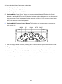
Table-Top Delegate Mic CS-200DU Unit
○,1
○,2
○,3
○,4
11
12
7
1
Talk Indicator lamp
Status Indicator lamp
Voting/Control Button &
Indicator lamp
○,5 Voting Case Cover
10
2
Talk Button
4
3
4
Control
8
2
Talk
9
5
6
5
3
1
○,6 Record Output Jack
○,7 Earphone Output Jack
○,8 Earphone Volume Control
○,9 LCD
○,10 MIC Jack
○,11 Built-In Speaker
○,12 Hidden Wiring Slot
Functions:
53.6
169.3
131.8
131.8
12
1. CS-200DUB does not have LCD screen, the rest function is as same as CS-200DU.
1.1 Power On:All the LCDs (including Chairman/Delegate MIC) will be displayed as following when
the power is on; it means the connection is ok. You can press any button of the microphone or
wait until 30 sec to another preset picture.
W e l c o m e
C o n f e r e n c e
t o
P A
B X B
S y s t e m
1.2 Preset Picture
1
2
N O :
N o
M i c
M O D E :
N o r m a
l
1. NO:MIC ID Code (including MIC in use/request/line-up)
2. MODE:Mode In Use(Please refer the main control unit instructions for Mode functions)
2. Press Talk button, when the indicator lamp of Talk and microphone is on, talking can begin.
25
3. Lamp color definition of conference mode status.
Red Light On:Chairman Mode
Orange Light On: FIFO Mode
Green Light On: Override Mode
4. Chairman Mode: While pressing the “TALK” button by the chairman, the ring of LED and talk indicator
lamp of delegate microphones are flashing with RED color, once the chairman permits speaking, and
the ring of LED will be automatically turned to red color without flashing, the delegates can speak
now.
5. FIFO Mode: The 1st prepared speaker will see his microphone’s LED ring and talk indicator lamp start
flashing with RED color, once the last one finished speaking; all the lamps will be automatically
turned to red color without flashing. Now it’s his turn. The 2nd prepared speaker and next ones will
see their microphone’s LED rings and talk indicator lamps start flashing with ORANGE color, once
the 1st prepared speaker finished speaking, the lamps of the 2nd one will be automatically turned to
orange color without flashing, and so on.
6. Execute voting function- this function can be enabled only when the chairman main control unit is
configured with graphic control software. The voting buttons are hidden in the voting cabin, which
can be opened while voting is required. When voting is finished, the cabin can be covered to
maintain the simple and grace appearance of the conference microphones.
6.1 The definition of each button is as follows:
6.1.1 Voting Mode: ○,1:Yes ○,2: No ○,3○,4○,5: Abstain
6.1.2 Electing Mode: ○,1: 1 ○,2:2 ○,3:3 ○,4:4 ○,5:5
6.1.3 ○,1: ++(Strongly agree) ○,2: +(Agree) ○,3: 0(No opinion)
○,4:-(Disagree) ○,5:- -(Strongly Disagree)
6.2 Two ways of Voting: Registered or Ballot
6.2.1 Registered:
6.2.1.1 Before voting, five lamps will be on simultaneously, which mean the voting can be
executed. Press the button you want and the corresponding red lamps will be
constantly on which indicate the voting is successful. When voting is stopped, all five
lamps will be start flashing which indicate the system is calculating the votes, once the
calculation is finished, it will stop flashing.
6.2.1.2 The voting results and voter’s selection could be seen on the LCD of CS-200CU/DU
Graphic Control Software. Only can the LCD of chairman/delegate display as
followings:
T :
x x x
A :
x x x
1
26
:
x x x
2
:
x x x
3 :
x x x
4
:
x x x
5
:
x x x
【T:Total voters】 【A:Abstained voters】 【1:Voters for No.1】 【2:Voters for No.2】
【3:Voters for No.3】 【4:Voters for No.4】 【5:Voters for No.5】
6.2.2Ballot:
6.2.2.1 Before voting, five lamps will be on simultaneously, which mean the voting can be executed.
For strengthening the confidentiality, when you press the button, the corresponding red
lamps will be flashing twice and then disappeared immediately which indicate the
successful voting. When voting is stopped, all five lamps will be start flashing which indicate
the system is calculating the votes, once the calculation is finished, it will stop flashing.
6.2.2.2 The voting results could be seen on the LCD of Graphic Control Software and the LCD of
chairman/delegate display, only the voter’s selection cannot be seen. Before all the five
lamps flashing, the selection can be changed.
7. Chairman Multi-Functional Control Button: The functions and operations are as same as the
main control unit.
8. LCD can display the MIC ID Code (including MIC in use/request/line-up) and the conference mode.
MODE
UP
DOWN
3
2
STEP
SAVE
4
5
1
9. The gooseneck microphones are separate with the stand to facilitate the installation, repair and
maintenance in general condition as well as the transportation, storage and assembly.
10.Hidden wiring is adopted with Y-shaped fast cord. There is a hidden configuration slot for connector in
the stand. Holes can be drilled under the stand when installed, which will enable hidden wiring and
maintain the appearance of the conference hall nice and neat.
27
Table-Top Delegate Mic- CS-200DU Unit
8
9
7
4
3
Status
5
2
Talk
6
○,1 Talk Button
○,2 Talk Indicator lamp
○,3 Control Indicator lamp
○,4 Record Output Jack
○,5 Earphone Output Jack
○,6 Earphone Volume Control
○,7 LCD
○,8 MIC Jack
○,9 Built-In Speaker
○,10 Voting Function Case
○,11 Hidden Wiring Slot
10
1
53.6
169.3
131.8
131.8
11
Functions:
1. CS-200DUB does not have the LCD screen, but the rest functions are as same as CS-200DU.
1.1 Power On “Welcome” Picture:All the LCDs (including Chairman/Delegate MIC) will be displayed
as following when the power is on; it means the connection is ok. You can press any button of the
microphone or wait until 30 sec to another preset picture.
W e l c o m e
C o n f e r e n c e
t o
P A
B X B
S y s t e m
1.2 Preset Picture
1
2
N O :
N o
M i c
M O D E :
N o r m a
l
1. NO:MIC ID Code (including MIC in use/request/line-up)
2. MODE:Mode In Use(Please refer the main control unit instructions for Mode functions).
2. Press Talk button, when the indicator lamp of Talk and microphone is on, talking can begin.
3. Lamp color definition of conference mode status.
28
3.1 Red Light On:Chairman Mode
3.2 Orange Light On: FIFO Mode
3.3 Green Light On: Override Mode
4. Chairman Mode: While pressing the “TALK” button by the chairman, the ring of LED and talk indicator
lamp of delegate microphones are flashing with RED color, once the chairman permits speaking, and
the ring of LED will be automatically turned to red color without flashing, the delegates can speak
now.
5. FIFO Mode: The 1st prepared speaker will see his microphone’s LED ring and talk indicator lamp start
flashing with RED color, once the last one finished speaking; all the lamps will be automatically turned
to red color without flashing. Now it’s his turn. The 2nd prepared speaker and next ones will see their
microphone’s LED rings and talk indicator lamps start flashing with ORANGE color, once the 1st
prepared speaker finished speaking, the lamps of the 2nd one will be automatically turned to orange
color without flashing, and so on.
6. Execute voting function- this function can be enabled only when the chairman main control unit is
configured with graphic control software. The voting buttons are hidden in the voting cabin, which can
be opened while voting is required. When voting is finished, the cabin can be covered to maintain the
simple and grace appearance of the conference microphones.
a.The definition of each button is as follows:
b.Voting Mode: ○,1:Yes ○,2: No ○,3○,4○,5: Abstain
c. Electing Mode: ○,1: 1 ○,2:2 ○,3:3 ○,4:4 ○,5:5
d. ○,1: ++(Strongly agree) ○,2: +(Agree) ○,3: 0(No opinion)○,4:-(Disagree) ○,5:- (
- Strongly
Disagree)
Two ways of Voting: Registered or Ballot
Registered:
Before voting, five lamps will be on simultaneously, which mean the voting can be executed. Press
the button you want and the corresponding red lamps will be constantly on which indicate the voting
is successful. When voting is stopped, all five lamps will be start flashing which indicate the system
is calculating the votes, once the calculation is finished, it will stop flashing.
The voting results and voter’s selection could be seen on the LCD of FCS 6170 Graphic Control
Software. Only can the LCD of chairman/delegate display as followings:
T :
3 :
x x x
x x x
A :
4 :
x x x
x x x
1
5
:
:
x x x
x x x
2
:
x x x
【T:Total voters】 【A:Abstained voters】 【1:Voters for No.1】 【2:Voters for No.2】
【3:Voters for No.3】 【4:Voters for No.4】 【5:Voters for No.5】
Ballot:
29
Before voting, five lamps will be on simultaneously, which mean the voting can be executed. For
strengthening the confidentiality, when you press the button, the corresponding red lamps will be
flashing twice and then disappeared immediately which indicate the successful voting. When voting
is stopped, all five lamps will be start flashing which indicate the system is calculating the votes,
once the calculation is finished, it will stop flashing.
7. The voting results could be seen on the LCD of Graphic Control Software and the LCD of
chairman/delegate display, only the voter’s selection cannot be seen. Before all the five lamps
flashing, the selection can be changed.
8. LCD can display the MIC ID Code (including MIC in use/request/line-up) and the conference mode.
9. The gooseneck microphones are separate with the stand to facilitate the installation, repair and
maintenance in general condition as well as the transportation, storage and assembly.
10.Hidden wiring is adopted with CS-200YC fast cord. There is a hidden configuration slot for connector
in the stand. Holes can be drilled under the stand when installed, which will enable hidden wiring and
maintain the appearance of the conference hall nice and neat.
30
Table-Top Chairman Mic- CS-200CU Unit
○,1
○,2
○,3
○,4
○,5
11
12
10
Talk Button
Talk Indicator lamp
Chairman Control Button
Status Indicator lamp
Voting/Control Button &
Indicator lamp
○,6 Voting Case Cover
7
1
4
2
3
4
Control
8
2
Talk
9
5
6
5
3
1
○,7 Record Output Jack
○,8 Earphone Output Jack
○,9 Earphone Volume Control
○,10 LCD
○,11 MIC Jack
○,12 Built-In Speaker
○,13 Hidden Wiring Slot
53.6
169.3
131.8
131.8
13
Functions:
1.1 Power On “Welcome” Picture:All the LCDs (including Chairman/Delegate MIC) will be displayed
as following when the power is on; it means the connection is ok. You can press any button of the
microphone or wait until 30 sec to another preset picture.
W e l c o m e
C o n f e r e n c e
t o
P A
B X B
S y s t e m
1.2 Preset Picture
1
2
N O :
N o
M i c
M O D E :
N o r m a
l
1 NO: MIC ID Code (including MIC in use/request/line-up)
2 MODE: Mode In Use(Please refer the main control unit instructions for Mode functions).
2. Press Talk button, when the indicator lamp of Talk and microphone is on, talking can begin.
3. Clear all delegate talking-press Control button to clear all the delegates.
31
4. Lamp color definition of conference mode status.
4.1 Red Light On:Chairman Mode
4.2 Orange Light On: FIFO Mode
4.3 Green Light On: Override Mode
5.
Chairman Mode: Press “Control” button for three seconds until the red LED above the Control
button is on and the MODE on the LCD displays Chairman and the chairman mode can be executed;
vice verse, press Control button again for three seconds until the red LED above the Control button
is off, it will resume to normal talking status.
6.
Chairman Multi-Functional Control Button: The functions and operations are as same as the
main control unit.
MODE
UP
2
DOWN
3
STEP
SAVE
4
5
1
7.
LCD can display the MIC ID Code (including MIC in use/request/line-up) and the conference mode.
8.
The gooseneck microphones are separate with the stand to facilitate the installation, repair and
maintenance in general condition as well as the transportation, storage and assembly.
9.
Hidden wiring is adopted with CS-200YC. There is a hidden configuration slot for connector in the
stand. Holes can be drilled under the stand when installed, which will enable hidden wiring and
maintain the appearance of the conference hall nice and neat.
32
Table-Top Delegate Mic- CS-200DU Unit
8
9
7
4
3
Status
Talk
5
2
6
○,1 Talk Button
○,2 Talk Indicator lamp
○,3 Control Indicator lamp
○,4 Record Output Jack
○,5 Earphone Output Jack
○,6 Earphone Volume Control
○,7 LCD
○,8 MIC Jack
○,9 Built-In Speaker
○,10 Voting Function Expanded
Case
○,11
Hidden Wiring Slot
10
1
53.6
169.3
131.8
131.8
11
Functions:
1. CS-200DUB does not have the LCD screen, but the rest functions are as same as CS-20DU.
1.1 Power On “Welcome” Picture:All the LCDs (including Chairman/Delegate MIC) will be displayed
as following when the power is on; it means the connection is ok. You can press any button of the
microphone or wait until 30 sec to another preset picture.
W e l c o m e
C o n f e r e n c e
t o
P A
B X B
S y s t e m
1.2 Preset Picture
1
2
N O :
N o
M i c
M O D E :
N o r m a
l
1 NO:MIC ID Code (including MIC in use/request/line-up)
2 MODE:Mode In Use(Please refer the main control unit instructions for Mode functions).
33
2. Press Talk button, when the indicator lamp of Talk and microphone is on, talking can begin.
3. Lamp color definition of conference mode status.
3.1 Red Light On:Chairman Mode
3.2 Orange Light On: FIFO Mode
3.3 Green Light On: Override Mode
4. Chairman Mode: While pressing the “TALK” button by the chairman, the ring of LED and talk
indicator lamp of delegate microphones are flashing with RED color, once the chairman permits
speaking, and the ring of LED will be automatically turned to red color without flashing, the delegates
can speak now.
5. FIFO Mode: The 1st prepared speaker will see his microphone’s LED ring and talk indicator lamp
start flashing with RED color, once the last one finished speaking; all the lamps will be automatically
turned to red color without flashing. Now it’s his turn. The 2nd prepared speaker and next ones will
see their microphone’s LED rings and talk indicator lamps start flashing with ORANGE color, once
the 1st prepared speaker finished speaking, the lamps of the 2nd one will be automatically turned to
orange color without flashing, and so on.
6. LCD can display the MIC ID Code (including MIC in use/request/line-up) and the conference mode.
7. The gooseneck microphones are separate with the stand to facilitate the installation, repair and
maintenance in general condition as well as the transportation, storage and assembly.
8. Hidden wiring is adopted with CS-200YC. There is a hidden configuration slot for connector in the
stand. Holes can be drilled under the stand when installed, which will enable hidden wiring and
maintain the appearance of the conference hall nice and neat.
34
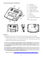
Appendix. Speed Dome Basic Setting
1.1 Power On & Off
Before the speed dome connects with other equipments, user has to complete the related
settings of IP address and protocols. Please see the following pictures:
A
Reserved port
B
Communication Switch
C
IP Address Switch
D
Protocol Switch
E
RJ-45 connecting port (for Speed Dome)
F
Data Transmission Connector (22-Pin
Connector)
1.2 Telecom On& Off
Communication Switch
Pin 1
Pin 2
RS-485 Communication Setting
Pin 3
Termination
Pin 4
Line Lock
Pin 5
System Initialization (for upgrade)
Pin 6
Reserved
35
RS-485 Communication Setting
Half Duplex
Full Duplex
The factory setting of RS-485 is Half-Duplex.
Note: Do not change the settings without the instructions of professional technicians.
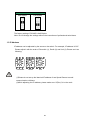
1.3 IP Address
IP address can be adjusted by the arrow on the switch. For example, IP address is”123.”
Please adjust it with the order of Percentile (1), Decile (2) and Unit (3). Please see it as
following:
Percentile
Decile
Unit
(1)Please do not set up the identical IP address of two Speed Domes to avoid
communication collisions.
(2)While adjusting the IP address, please make sure “0(Zero)” is in the north.
36
2.1 Telecom Protocol
Switch No.
Protocol
Baud Rate
00
VCL
9600
01
Pelco D
2400
02
Pelco P
4800
04
Chiper
9600
05
Philips
9600
07
BXB
9600
08
AD422
4800
09
DM P
9600
11
Pelco D
4800
12
Pelco D
9600
13
Pelco P
2400
14
Pelco P
9600
15
JVC
9600
16
GANZ
9600
For example, if your protocol is “Pelco D”, the baud rate is 2400, Switch no is 01, and the
setting is as follows:
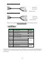
2.2 Definition of Data Transmission Cord
For user’s convenient fast installation and test, this IP Speed Dome contains a 50 centimeters
data transmission cord; Data transmission cord varies depend on the product models(DC 12V
or AC 24V ).
Please refer to the following pictures:
37
Data Transmission Cord: DC 12V
Data Transmission Cord: AC 24V
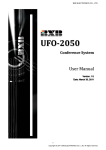
Please see the following 22-Pin DefinitionTable as connecting referenece.
Pin
Definition
1
AC24-1/DC GND
2
Alarm Pin (Not wired)
3
AC24-2/DC12 (+)
4
Alarm Pin (Not wired)
5
FG
6
Alarm Pin (Not wired)
7
T+
8
R-
9
T-
10
R+
11~20
AWG
20AWG
20AWG
20AWG
24AWG
Alarm Pin (Not wired)
21
Video GND Cable
22
Video Cable
24AWG
RS-485 is the communication interface between IP Speed Dome and control keyboard; If 24-gauge cord
is adopted to use, the maximum length of cable is 4000 feet (1219 meters). Twisted Pair Cable is
recommended.
38
39