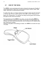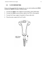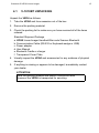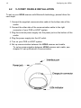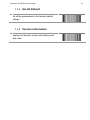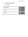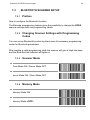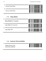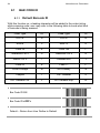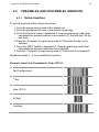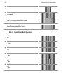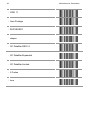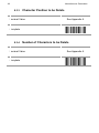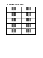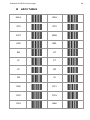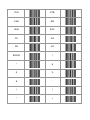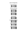
1
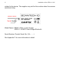
User’s Manual VEGA Linear Imager V-1010/V-1010BT Handheld Bar code Scanner EMEA SCANTECH-ID BV Nijverheidsweg Noord 60-34 3812 PM Amersfoort The Netherlands Tel:+31-33-4698400 Fax:+31-33-4650615 E-mail:[email protected] www.scantech-id.com HEAD QUARTER CHAMPTEK INCORPORATED 5/F, No.2 Alley 2, Shih-Wei Lane, Chung Cheng Rd., Hsin Tien City, Taipei 231,Taiwan Tel:+886-2-2219-2385 Fax:+886-2-2219-2387 E-mail:[email protected] www.champtek.com China CHAMPTEK INCORPORATED #901, No. 39, Wuzhong Rd., Shanghai 200235, China Tel: +86-21-5489-0021 Fax: +86-21-5489-1833 Notice The manufacturer shall not be liable for technical or editorial errors or omissions contained herein; nor for incidental or consequential damages in connection with the furnishing, performance or use of the publication User’s Installation and Configuration Manual Scantech-ID VEGA Copyright © 2009, Scantech-ID BV. This manual is copyrighted, with all rights reserved. Under the copyright laws, this manual may not, in whole or in part, be copied, photocopied, reproduced, translated or converted to any electronic medium or machine readable form without prior written consent of Scantech-ID BV. Limited Warranty Under all circumstances this manual should be read attentively, before installing and/or using the product. In no event shall Scantech-ID BV be liable for any direct, indirect, special, consequential or incidental damages arising out of the use or inability to use this documentation or product, even if advised of the possibility of such damages. In particular, Scantech-ID BV shall not be liable for any hardware, software, or data that is stored or used with the product, including the cost of repairing, replacing or recovering the above. Scantech-ID BV reserves the right to change parts of the device at any time without preceding or direct announcement to the client. Scantech-ID BV reserves the right to revise this manual, and to make changes in the contents without obligation to notify any person or entity of the revision or change. A serial number appears on the product. Make sure that this official registration number has not been removed. It should be used whenever servicing by Scantech-ID BV or an authorized Scantech dealer is necessary. P/N A270003 V1.0 April 2009 1 Table of contents Table of Contents ...................................................................................... 1 Introduction................................................................................................ 4 Chapter 1 Product Safety 5 1.1 Safety & Caution............................................................. 6 1.2 FCC Warning.................................................................. 7 1.3 Scanner Labelling ........................................................... 8 Chapter 2 General Description 9 2.1 Use of the VEGA ...........................................................10 Chapter 3 Installation of the VEGA V-1010 11 3.1 Unpacking .....................................................................12 3.2 Mounting .......................................................................13 Chapter 4 Installation of the VEGA V-1010BT 14 4.1 Unpacking .....................................................................15 4.2 Cradle Installation ..........................................................16 4.3 Setup Bluetooth Communication ....................................17 Chapter 5 Cover Display 20 5.1 Setup Cover Display ......................................................21 2 Chapter 6 Configuring the VEGA 25 6.1 Preface ......................................................................... 26 6.2 Factory Default Setting .................................................. 28 Chapter 7 Programming Codes 29 7.1 General Process ........................................................... 30 7.2 Interface Selection ........................................................ 32 7.3 Bluetooth Scanner Setup. .................33 7.4 Bluetooth Cradle Setup ................................................. 36 7.5 Scanner Operation ........................................................ 37 7.6 RS232 Mode Parameters .............................................. 40 7.7 Keyboard Wedge Mode Parameters...........43 7.8 Output Characters......................................................... 47 7.9 Code Type .................................................................... 48 7.10 UPC/EAN/JAN Parameters ........................................... 52 7.11 Code 39 Parameters ..................................................... 55 7.12 Code 128 Parameters ................................................... 58 7.13 Interleave 2 of 5 Parameters ......................................... 61 7.14 Industrial 2 of 5 Parameters .......................................... 64 7.15 Matrix 2 of 5 Parameters ............................................... 67 7.16 Codabar/NW7 Parameters ............................................ 69 7.17 Code 93 Parameters ..................................................... 72 7.18 Code 11 Parameters ..................................................... 74 7.19 MSI/Plessey Code Parameters...................................... 76 7.20 Telepen Parameters...................................................... 78 7.21 GS1 Databar Parameters .............................................. 80 7.22 GS1 Databar Limited Parameters .................................. 81 7.23 GS1 Databar Expanded Parameters ............................. 82 Scantech-ID VEGA Linear Imager 3 Chapter 8 Miscellaneous Parameters 83 8.1 Bar Code ID...................................................................84 8.2 Preambles and Postambles Insertion .............................87 8.3 Character Deletion.........................................................92 Appendices............................................................................................... 97 A Decimal Value Table ...........................................................98 B ASCII Table ........................................................................99 C Function Key Table...........................................................105 D Readable Symbologies .....................................................106 E Technical Specifications....................................................107 F Scan Map .........................................................................109 G Led Indicator Status..........................................................111 H Test Symbologies .............................................................112 I Overview Partnumbers .......................................................114 4 Introduction VEGA is a cutting-edge gun-type barcode scanner which is designed specifically for retail market. To the brand new series of VEGA, we add on more user-friendly functions with detachable cable that makes it more easily to be operated by the customers. Speaking of the performance, this scanner supports middle to long range mode. For specification of VEGA which supports the reading depth up to 27 centimeter, scan rate is up to 700 scans / per second. The new VEGA scanner has most modern design with the decorative cover display on the top of the scanner that will enhance the looks of the checkout counter in the retail market. This magnificent design allowed end-users to display their product information or any relevant commercial message in the cover display. This advanced mechanical design truly creates a win-win solution for both POS retail systems and consumers. In short, VEGA is absolutely a high performance gun-type scanner, which provides the customer with the most cost-effective solution in the market. It is perfectly suitable and definitely the best choice for any retailers using POS environment. Quality and Durability The VEGA comes with the same top quality as all other Scantech-ID products. So at a very competitive price the same quality and performance of more expensive products is available. Due to the high MTBF times of every component a long and service free operation time is secured. Connectivity The VEGA is available into interface types, RS232 interface, USB interface and also with Bluetooth technology, so there is always a solution to connect the Vega to your POS system. 5 Chapter 1 Product Safety 6 Installation of the VEGA V-1010 1.1 1. 2. 3. 4. 5. 6. 7. 8. 9. 10. 11. 12. 13. SAFETY & CAUTION Please read the following safety statement carefully. Please preserve this user manual for reference sometime. Before cleaning the VEGA, the users must cut off all AC power. Do not use liquid or spray type of detersive to clean the VEGA. Please use dampish cotton cloth to clean the VEGA. The outlet must set nearby the VEGA for connecting power easily. Keep the VEGA dry to avoid short circuit. During installation you must fix the equipment at solid table to avoid damage caused by falling. Before inserting power please ensure the voltage is healthy to the equipment. For safety please tie wire well and don’t put anything on the wire. If you don’t use this equipment for long time, please cut off the power to avoid damage from surge power. Don’t spray any liquid on this scanner because it may cause a fire or short circuit. Please do not open the equipment. For safety only the qualified serviceman can open the equipment. If there are the following situations please contact with the qualified serviceman to check this equipment. (a) The damage of wire or pin of power supply. (b) Some Liquid infiltrate into the equipment. (c) The equipment has been exposed to wet environment. (d) The equipment can’t work well. (e) The equipment has any obvious damage, making the VEGA working abnormally. Don’t storage the VEGA at the temperature lower than -20°C (-4°F) or higher than +70°C (158°F) to avoid any damage. 1.2 FCC WARNING This equipment complies with the requirements in Part 15 of FCC. Scantech-ID VEGA Linear Imager 7 Any operation must comply with the conditions below: (a) The equipment will not cause any severe interference. (b) The equipment can avoid any interference from environment. Statement: This product is classified as B class product. In environment this product may cause some interference. In this situation the user may do something to avoid interference. 1.3 SCANNER LABELLING One label is present on the housing of the VEGA as indicated in the figure below. This label is attached by the manufacturer and should not be removed. The scanner serial number is found on this label. This official registration is strictly 8 Installation of the VEGA V-1010 related to the device. The supplier may ask for this number when the scanner needs servicing. Model Name Serial Number Model Name: VEGA V-1010 Linear Imager VEGA V-1010BT Linear Imager Bluetooth Serial Number: Product Serial No. (VA……..) See Appendix F for more information in detail. Scantech-ID VEGA Linear Imager Chapter 2 General Description 9 10 Installation of the VEGA V-1010 2.1 USE OF THE VEGA The VEGA is very ergonomic and modern designed and very user friendly. It can be connected to your POS or Host system trough a RS232 cable, KBW cable, USB cable or with Bluetooth wireless. To read a bar code, you simply press the red trigger button and aim the beam to the bar code. But you need to position the beam so that it falls across all bars in the 1D barcodes. You will hear one beep and the green LED indicator will lights on after scan successfully. The programming of the VEGA is very easy, you can set-up the VEGA by scan all necessary programming codes one time that meet applications, the settings are directly saved permanently, and all settings can be disabled after scan reset factory default. Thanks to the power full decoding processor, the VEGA can decode all major 1D codes. Scantech-ID VEGA Linear Imager Chapter 3 Installation of the VEGA V-1010 11 12 Installation of the VEGA V-1010 3.1 V-1010 UNPACKING Unpack the VEGA as follows: 1. Take the VEGA and its accessories out of the box. 2. Remove the packing material. 3. Check the packing list to make sure you have received all of the items ordered. Standard Shipment Package a. VEGA linear imager handheld bar code scanner b. Power Adaptor if apply c. User Manual d. Communication Cable e. Stand f. Transparent Cover Plate 4. Visually inspect the VEGA and accessories for any evidence of physical damage. 5. If anything is missing or appears to be damaged, immediately contact your dealer. ATTENTION Store the packing material and boxes: it should be used whenever the VEGA is transported for servicing. Scantech-ID VEGA Linear Imager 3.2 13 V-1010 MOUNTING Once you have unpacked all components, you can start installing the VEGA. Installing the VEGA is divided in different steps: 1. Connect the VEGA to the supplied communication cable (RJ45 side). 2. Connect the VEGA communication cable to the POS or Host system. 3. Connect the Power supply (if needed) to Power cable inlet. 4. Plug the power supply into the AC outlet. 14 Chapter 4 Installation of the VEGA V-1010BT/V1010BT Scantech-ID VEGA Linear Imager 4.1 15 V-1010BT UNPACKING Unpack the VEGA as follows: 1. Take the VEGA and its accessories out of the box. 2. Remove the packing material. 3. Check the packing list to make sure you have received all of the items ordered. Standard Shipment Package a. VEGA Linear Imager Handheld Bar code Scanner Bluetooth b. Communication Cable (RS-232 or Keyboard wedge or USB) c. Power adaptor d. User Manual e. Bluetooth Cradle or charger f. Transparent Cover Plate 4. Visually inspect the VEGA and accessories for any evidence of physical damage. 5. If anything is missing or appears to be damaged, immediately contact your dealer. ATTENTION Store the packing material and boxes: it should be used whenever the VEGA is transported for servicing. 16 Configuring the VEGA 4.2 V-1010BT CRADLE INSTALLATION To set up your VEGA scanner with Bluetooth technology, please follow the next steps. 1. Connect the supplied communication cable at the bottom side of the cradle. 2. Connect the other side of the communication cable to the right connector of your POS or HOST system. 3. Plug the external power supply into the power jack on the bottom of the cradle. 4. Plug the power supply into the AC outlet. 5. Turn on your POS or HOST system. 6. Set up communication between the VEGA scanner and cradle. To set up communication between VEGA scanner and cradle, see chapter 4.3 set up Bluetooth Communication. Scantech-ID VEGA Linear Imager 4.3 17 V-1010BT SET UP BLUETOOTH COMMUNICATION Before the VEGA scanner can be used for normal operation, Bluetooth communication must be set up between the VEGA scanner and cradle, Scanner client mode or to a Bluetooth application device, Scanner Server mode. 4.3.1 Pairing Pairing refers to when a VEGA scanner has been linked or paired to a specific cradle by scanning that cradle’s Bluetooth MAC address code, this Bluetooth MAC address code is unique for each cradle. This address code is located on the bottom side of the cradle. The pairing of a VEGA scanner to a cradle is one to one. Only one VEGA scanner can be paired to a cradle at any point in time. 4.3.2 Set up Client Mode Communication To set-up the communication between the VEGA scanner and the cradle follow the next steps: 1. The VEGA scanner must scan “Scanner Client Mode ON/Scanner Server Mode Off” barcode, to set the VEGA scanner in client mode. 2. Scan the Bluetooth MAC address code located on the bottom of the cradle. 3. When the Bluetooth MAC was successfully scanned, scanner will initiate with short beep sounds. Blue and red led will also blink followed by a long beep sound. Wait approximately five seconds, for completing the connection process. Blue led will slow flash on scanner for connected the cradle. 4. 5. If successful, the blue led on the cradle will be on. 6. If the connections failed the scanner indicates with shot beep sounds and the cradle with blinking blue led. 18 Configuring the VEGA ATTENTION The VEGA scanner must be charged for a minimum of 8 hours before the scanner can be placed in full operation for the first time. The cradle red led will indicate in red when the scanner is charged. After the battery is full, The charge green light will be light.The charge green light will be off when the scanner leaving from cradle. If the battery power of the VEGA is too low, the VEGA will indicate this with red led and beeper warning. BT MAC Address It is important to know that the VEGA scanner will only communicate with the cradle whose unique Bluetooth MAC address was the last address scanned. If a cradle is paired with the VEGA scanner, another VEGA scanner can’t be paired with that cradle until the original connection is broken. If you pair a second VEGA scanner to an in use cradle, the cradle’s connection to the first VEGA scanner will be broken and the connection reestablished with the second VEGA scanner. 4.3.3 Set up Server Mode Communication To set-up the communication between the VEGA scanner and Bluetooth application device follow the next steps. 1. The VEGA scanner must scan “Scanner Server Mode ON/Scanner Client Mode Off” barcode, to set the VEGA scanner in server mode. Scantech-ID VEGA Linear Imager 2. 3. 19 When control the Bluetooth device to search the scanner, enter pin code (default 00:00:00:00) to setup comport. When VEGA scanner is successful connected, scanner will initiate with short beep sounds. Blue and red led will also blink followed by a long beep sound. Blue led will slow flash to finish the set up. 4.3.4 Sleep Mode The VEGA scanner is equipped with sleep mode function to save battery energy, when the VEGA scanner is not used for 1 minute or 10 minute time (option 10 minute). During sleep mode all the functions and connection will be halted, after press the red trigger button the scanner can be wake up and reconnect the communication with the cradle or Bluetooth device. By scanning the according programming code, see chapter 7. 4.3.5 Memory Mode This memory mode function is enabled when you have scanned “memory on” barcode. Scanning data is stored in the memory of the VEGA scanner. This function is disabled when you have scanned “memory off” barcode. When scan barcode “memory read” barcode stored data will be immediately transmit to the cradle after reconnection. when scan barcode “memory clear” barcode all stored memory data will be erased. The capacity of this memory depends on the scanned data size, approximately 50 sets of data. 20 Configuring the VEGA Chapter 5 Cover Display Scantech-ID VEGA Linear Imager 5.1 SETUP COVER DISPLAY The VEGA scanner has the opportunity to change the decorative cover display on the top of the scanner into a display that can show our own commercial message. 5.1.1 Message Format Create your own commercial message with the following outline format, use thicker paper 5.1.2 Change Cover Display Follow the next instruction steps to change the black Cover Display into the transparent Cover Display, so that your customers can read your own commercial massage. 21 22 Configuring the VEGA Step 1: Press out the front rubber lid toward the arrow. ➀ Step 2: Pull out the front rubber lid off the main unit. ➁ Step 3: Press out top cover rim from the inner lock. ➂ Scantech-ID VEGA Linear Imager 23 Step 4: Press out the other side of inner lock and remove the complete cover. ➃ Step 5 Assemble transparent top cover rim into inner lock. ➄ Step 6 Assemble another side transparent top cover rim into the inner lock. ➅ 24 Configuring the VEGA Step 7 Insert your commercial message card into the top cover toward the arrow. ➆ Step 8 Assemble the front rubber lid into the main unit toward the arrow. ➇ Scantech-ID VEGA Linear Imager Chapter 6 Configuring the VEGA 25 26 Configuring the VEGA 6.1 PREFACE How to configure the VEGA: The Barcode programming feature gives the possibility to change the VEGA scanner settings with use programming labels. 6.1.1 Changing Scanner Settings with Programming Codes You can set-up your VEGA by scan all necessary programming codes for parameters that meet applications. In order to change the scanner settings please follow the sequence below: 1. Power-up the scanner. 2. Open the scanner programming mode by scanning Start Configuration. 3. Change scanner settings by scanning any of the programming code that meet applications. 4. Close the scanner programming mode by scanning End Configuration. 5. Save configuration by scanning Save Parameters An Example: For changing the Baud rate to 38400 the following codes must be scanned successively: Start configurationBaud rate 38400End configuration Save Parameters After reading a valid programming code the scanner will give a double High beep and the green led indicator will lights on. By scanning “Set All Default” label, the settings will go back to the factory default settings. Scantech-ID VEGA Linear Imager 6.1.2 27 Programming Flow Chart Start Configuration Recall Parameters Interface Selection Communication Parameters Bar codes Parameters Misc. Parameters etc. Abort End Configuration Configuration Save Parameters Set all Default 28 Configuring the VEGA 6.2 FACTORY DEFAULT SETTING The VEGA is set default with the following settings: RS232 COMMUNICATION Baud rate Parity Data bits Stop bits RTS/CTS Postamble DECODER SELECTION All UPC/EAN/JAN Code 11 Code 39 Code 39 Full ASCII Code 32 / Italian Pharmacy Code 128 Codabar/NW7 GS1 Databar RSS-14 GS1 Databar Expanded GS1 Databar Limited Interleave 2 of 5 Industrial 2 of 5 Matrix 2 of 5 MSI/Plessey Telepen China Postage CODE IDENTIFIERS Code Identifiers DEFAULT V-1010:9600 V-1010BT:19200 None 8 1 Off <CR+LF> DEFAULT On Off On Off Off On On Off Off Off On Off Off Off Off Off DEFAULT Off The factory defaults settings are shown with <> and bold in the following chapters. 29 Chapter 7 Programming Codes 30 Miscellaneous Parameters 7.1 GENERAL PROCESS 1 Power up the Scanner 2 Scan the Start of Configuration bar code Scan the bar code for the desired feature. You can scan all features before 3 scanning End of Configuration. 4 Scan End of Configuration bar code 5 Scan Save Parameters bar code 7.1.1 Abort Configuration Terminate current programming status. 7.1.2 Recall Replace the current parameters by the parameters saved last time Scantech-ID VEGA Linear Imager 7.1.3 Set All Default Set all the parameters to the factory default settings 7.1.4 Version Information Display the decoder version information and date code 31 32 Miscellaneous Parameters 7.2 INTERFACE SELECTION 7.2.1 Interface <Keyboard Mode> RS232 Mode USB Mode Scantech-ID VEGA Linear Imager 7.3 7.3.1 33 BLUETOOTH SCANNER SETUP Preface How to configure the Bluetooth function: The Barcode programming feature gives the possibility to change the VEGA scanner settings with use programming labels. 7.3.2 Changing Scanner Settings with Programming Codes You can set-up Bluetooth function by direct scan all necessary programming codes for Bluetooth parameters. After reading a valid programming code the scanner will give a High-low beep and the Blue-Red led indicator will lights on. 7.3.3 Scanner Mode Client Mode ON / Server Mode OFF Server Mode ON / Client Mode OFF 7.3.4 Memory Mode Memory Mode ON Memory Mode <OFF> 34 Miscellaneous Parameters Memory Read Mode Memory Clear Mode 7.3.5 Sleep Mode <Sleep Mode On 1 minute> Sleep Mode On 10 minute Sleep Mode OFF 7.3.6 Scanner Pincode Mode Default Security code (PINCODE=000000) Scantech-ID VEGA Linear Imager 35 Security Code ON Security Code OFF 7.3.7 Scanner Pincode Setup Set PINCODE Max 6 Digits, 0-9 and A-Z ASCII Code Go to ASCII table in Appendix B, scan 6 labels that represents the PINCODE Complete to Set PINCODE 36 Miscellaneous Parameters 7.4 BLUETOOTH CRADLE SETUP 7.4.1 Cradle Pincode Mode Default Security code (PINCODE=000000) Security Code ON Security Code OFF 7.4.2 Cradle Pincode Setup Set PINCODE Max 6 Digits, 0-9 and A-Z ASCII Code Go to ASCII table in Appendix B, scan 6 labels that represents the PINCODE Complete to Set PINCODE Scantech-ID VEGA Linear Imager 7.5 SCANNER OPERATION 7.5.1 Reading Mode <Good Read OFF> Trigger ON/OFF Continuous/Trigger OFF Continuous/Auto Power ON Flash Flash/Auto Power ON Testing 7.5.2 Good Read LED Control <Good Read LED ON> 37 38 Miscellaneous Parameters Good Read LED OFF 7.5.3 Beeper Option <High> Medium Low Off 7.5.4 Reading Level Bar Equals High <Bar Equals Low> 7.5.5 Accurany / Redundant Scan <Original> - Require 1 good decode for a good scan Scantech-ID VEGA Linear Imager 1 Redundant Scan - Require 2 consecutive decodes of the same bar code data for a good scan 2 Redundant Scan - Require 3 consecutive decodes of the same bar code data for a good scan 3 Redundant Scan - Require 4 consecutive decodes of the same bar code data for a good scan 7.5.6 Sensitivity of Continuous Reading This Feature is working under Reading Mode > Continuous modes <Fast> Slow 7.5.7 Reverse Output Characters Example: 012345 543210 Enable <Disable> 39 40 Miscellaneous Parameters 7.6 RS232 MODE PARAMETERS 7.6.1 Baud Rate 1200 2400 4800 <9600> for V-1010 <19200> for V-1010BT 38400 57600 Scantech-ID VEGA Linear Imager 7.6.2 Data/Stop Bits The number of data bits transmitted for each character 7 Data Bits < 8 Data Bits > < 1 Stop Bits > 2 Stop Bits 7.6.3 Parity A Parity bit is an extra data bit used to help catch data transmission errors. <None> Even – Select to set the parity bit either a 1 or 0 to ensure an even number of bits are 1’s Odd – Select to set the parity bit either a 1 or 0 to ensure an odd number of bits are 1’s Mark – Select to set the parity bit always 1. Space– Select to set the parity bit always 0. 41 42 Miscellaneous Parameters 7.6.4 Handshaking RTS/CTS ON – Output a Request to Send (RTS) signal and wait for a Clear to Send (CTS) signal before transmitting data RTS/CTS <OFF> ACK/NAK – After transmitting data, wait for host to send an ACK or a NAK response. If ACK is received, then complete the data transmission. If NAK is received, re-send the last set of data and wait for ACK/NAK again. ACK/NAK <OFF> XON/XOFF – After transmitting data, wait for host to send an XON or a XOFF response. If XON is received, then complete the data transmission. If XOFF is received, stop the transmission. XON/XOFF <OFF> Scantech-ID VEGA Linear Imager 7.7 KEYBOARD WEDGE MODE PARAMETERS 7.7.1 Terminal Type <IBM PC/AT,PS/2> - Includes IBM PS/2 and compatible models 50, 55, 60, 80 IBM PC/XT IBM PS/2 25, 30 IBM 5550 IBM 102 Key IBM 122 Key (1) IBM 122 Key (2) NEC 9800 Apple Desktop Bus(ADB) 43 44 Miscellaneous Parameters 7.7.2 Country/Language <US English> UK English Italian Spanish French German Swedish Switzerland Hungarian Japanese Belgium Scantech-ID VEGA Linear Imager Portuguese Denmark Netherlands Turkey 7.7.3 Upper/Lower Case <No Change> Enable Lower Case – Transmit all data as lower case Enable Upper Case – Transmit all data as upper case 45 46 Miscellaneous Parameters 7.7.4 Interscan Code Delay <No Delay> 5 ms 10 ms 25 ms 50 ms 100 ms 200 ms 300 ms Scantech-ID VEGA Linear Imager 7.8 OUTPUT CHARACTERS 7.8.1 Select Terminator <CR+LF>– The scanner transmits a carriage return and a line feed after each scan CR Suffix – The scanner transmits a carriage return after each scan LF Suffix – The scanner transmits a line feed after each scan Space Tab Alt Disable Alt STX-ETX – RS232 only 47 48 Miscellaneous Parameters 7.9 CODE TYPE 7.9.1 Barcode Selections If “Enable” is selected for all bar codes types, then the scanner could read all types of bar code. If “Disable” is selected for a certain bar code type, then the scanner could not read the particular bar code. The symbol of “<>” means default settings. All Bar Codes ON UPC-A <ON> UPC-A OFF UPC-E <ON> UPC-E OFF EAN-13 / JAN-13 <ON> EAN-13 / JAN-13 OFF EAN-8 / JAN-8 <ON> EAN-8 / JAN-8 OFF Scantech-ID VEGA Linear Imager CODE 39 <ON> CODE 39 OFF Standard Code 39 <ON> Full ASCII Code 39 ON Code32 / Italian Pharmacy ON Code32 / Italian Pharmacy <OFF> Code 128 <ON> Code 128 OFF Interleave 2 of 5 <ON> Interleave 2 of 5 OFF Codabar/NW7 <ON> Codabar/NW7 OFF 49 50 Miscellaneous Parameters Industrial 2 of 5 ON Industrial 2 of 5 <OFF> Matrix 2 of 5 ON Matrix 2 of 5 <OFF> CODE 93 ON CODE 93 <OFF> CODE 11 ON CODE 11 <OFF> MSI/PLESSEY ON MSI/PLESSEY <OFF> Telepen ON Telepen <OFF> Scantech-ID VEGA Linear Imager China Postage ON China Postage <OFF> GS1 DataBar ON GS1 DataBar <OFF> GS1 DataBar Expanded ON GS1 DataBar Expanded <OFF> GS1 DataBar Limited ON GS1 DataBar Limited <OFF> 51 52 Miscellaneous Parameters 7.10 UPC/EAN/JAN PARAMETERS 7.10.1 Reading Type UPC-A=EAN-13 ON Add 0 before UPC-A to make it 13 digits. UPC-A = EAN-13 <OFF> ISBN Enable ISBN <Disable> ISSN Enable ISSN <Disable> Decode with Supplement <Auto Discriminate Supplement> Expand UPC-E Enable <Expand UPC-E Disable> Scantech-ID VEGA Linear Imager EAN8=EAN13 Enable <EAN8=EAN13 Disable> GTIN Format Enable <GTIN Format Disable> 7.10.2 Supplemental Setup <Not Transmit> 2 Digit Supplemental 5 Digit Supplemental 2 & 5 Digit Supplemental 53 54 Miscellaneous Parameters 7.10.3 Check Digit Transmission UPC-A Check Digit Transmission <ON> UPC-A Check Digit Transmission OFF UPC-E Check Digit Transmission <ON> UPC-E Check Digit Transmission OFF EAN-8 Check Digit Transmission <ON> EAN-8 Check Digit Transmission OFF EAN-13 Check Digit Transmission <ON> EAN-13 Check Digit Transmission OFF ISSN Check Digit Transmission <ON> ISSN Check Digit Transmission OFF Scantech-ID VEGA Linear Imager 7.11 CODE 39 PARAMETERS 7.11.1 Type of Code <Standard Code 39> Full ASCII Code 39 7.11.2 Check Digit Transmission <Do Not Calculate Check Digit> Calculate Check Digit and Transmit Calculate Check Digit and Not Transmit 7.11.3 Output Start/Stop Character Enable <Disable> 55 56 Miscellaneous Parameters 7.11.4 Decode Asterisk Enable <Disable> 7.11.5 Set Up Code Length To set the fixed length: (2 sets Available) 1. Scan the “Begin” programming code of the desired set 2. Go to the Decimal Value Tables in Appendix A, scan programming codes that represents the length to be read. 3. Scan the “Complete” programming code of the desired set. Repeat the steps 1 – 3 to set additional lengths. <Variable> Fixed Length 1st Set 1st Set Begin Decimal Value 1st Set Complete Fixed Length 2nd Set See Appendix A Scantech-ID VEGA Linear Imager 57 2nd Set Begin Decimal Value See Appendix A nd 2 Set Complete Minimum Length Minimum Length Begin Decimal Value Minimum Length Complete See Appendix A 58 Miscellaneous Parameters 7.12 CODE 128 PARAMETERS 7.12.1 Reading Type UCC/EAN-128 Enable <UCC/EAN-128 Disable> 7.12.2 Check Digit Transmission Do Not Calculate Check Digit Calculate Check Digit and Transmit <Calculate Check Digit and Not Transmit> 7.12.3 Append FNC2 ON <OFF> Scantech-ID VEGA Linear Imager 59 7.12.4 Set Up Code Length To set the fixed length: (2 sets Available) 1. Scan the “Begin” programming code of the desired set 2. Go to the Decimal Value Tables in Appendix A, scan programming codes that represents the length to be read. 3. Scan the “Complete” programming code of the desired set. Repeat the steps 1 – 3 to set additional lengths <Variable> st Fixed Length 1 Set 1st Set Begin Decimal Value See Appendix A 1st Set Complete Fixed Length 2nd Set 2nd Set Begin Decimal Value 2nd Set Complete Minimum Length See Appendix A 60 Miscellaneous Parameters Minimum Length Begin Decimal Value Minimum Length Complete See Appendix A Scantech-ID VEGA Linear Imager 7.13 INTERLEAVE 2 OF 5 PARAMETERS 7.13.1 Check Digit Transmission <Do Not Calculate Check Digit> Calculate Check Digit and Transmit Calculate Check Digit and Not Transmit 7.13.2 Set Up Number of Character <Even> Odd 7.13.3 Brazilian Banking Code Enable <Disable> 61 62 Miscellaneous Parameters 7.13.4 Set Up Code Length To set the fixed length: (2 sets Available) 1 Scan the “Begin” programming code of the desired set 2 Go to the Decimal Value Tables in Appendix A, scan programming codes that represents the length to be read. 3 Scan the “Complete” programming code of the desired set. Repeat the steps 1 – 3 to set additional lengths <Variable> st Fixed Length 1 Set 1st Set Begin Decimal Value See Appendix A 1st Set Complete Fixed Length 2nd Set 2nd Set Begin Decimal Value 2nd Set Complete Minimum Length See Appendix A Scantech-ID VEGA Linear Imager 63 Minimum Length Begin Decimal Value Minimum Length Complete See Appendix A 64 Miscellaneous Parameters 7.14 INDUSTRIAL 2 OF 5 PARAMETERS 7.14.1 Reading Type IATA25 Enable <IATA25 Disable> 7.14.2 Check Digit Transmission <Do Not Calculate Check Digit> Calculate Check Digit and Transmit Calculate Check Digit and Not Transmit Scantech-ID VEGA Linear Imager 65 7.14.3 Set Up Code Length To set the fixed length: (2 sets Available) 1 1Scan the “Begin” programming code of the desired set 2 Go to the Decimal Value Tables in Appendix A, scan programming codes that represents the length to be read. 3 Scan the “Complete” programming code of the desired set. Repeat the steps 1 – 3 to set additional lengths <Variable> Fixed Length 1st Set 1st Set Begin Decimal Value See Appendix A 1st Set Complete Fixed Length 2nd Set 2nd Set Begin Decimal Value 2nd Set Complete Minimum Length See Appendix A 66 Miscellaneous Parameters Minimum Length Begin Decimal Value Minimum Length Complete See Appendix A Scantech-ID VEGA Linear Imager 7.15 MATRIX 2 OF 5 PARAMETERS 7.15.1 Check Digit Transmission <Do Not Calculate Check Digit> Calculate Check Digit and Transmit Calculate Check Digit and Not Transmit 7.15.2 Set Up Code Length To set the fixed length: (2 sets Available) 1 Scan the “Begin” programming code of the desired set 2 Go to the Decimal Value Tables in Appendix A, scan programming codes that represents the length to be read. 3 Scan the “Complete” programming code of the desired set. Repeat the steps 1 – 3 to set additional lengths <Variable> Fixed Length 1st Set 67 68 Miscellaneous Parameters 1st Set Begin Decimal Value See Appendix A st 1 Set Complete Fixed Length 2nd Set nd 2 Set Begin Decimal Value See Appendix A 2nd Set Complete Minimum Length Minimum Length Begin Decimal Value Minimum Length Complete See Appendix A Scantech-ID VEGA Linear Imager 7.16 69 CODABAR/NW7 PARAMETERS 7.16.1 Set Up Start/Stop Characters upon Transmission ON <OFF> 7.16.2 Transmission Type of Start/Stop A/B/C/D <Start> A/B/C/D <Stop> A Start A Stop B Start B Stop 70 Miscellaneous Parameters C Start C Stop D Start D Stop 7.16.3 Set Up Code Length To set the fixed length: (2 sets Available) 1 Scan the “Begin” programming code of the desired set 2 Go to the Decimal Value Tables in Appendix A, scan programming codes that represents the length to be read. 3 Scan the “Complete” programming code of the desired set. Repeat the steps 1 – 3 to set additional lengths <Variable> Fixed Length 1st Set Scantech-ID VEGA Linear Imager 71 1st Set Begin Decimal Value See Appendix A st 1 Set Complete Fixed Length 2nd Set nd 2 Set Begin Decimal Value See Appendix A 2nd Set Complete Minimum Length Minimum Length Begin Decimal Value Minimum Length Complete See Appendix A 72 Miscellaneous Parameters 7.17 CODE 93 PARAMETERS 7.17.1 Check Digit Transmission Do Not Calculate Check Digit <Calculate Check 2 Digit and Not Transmit> 7.17.2 Set Up Code Length To set the fixed length: (2 sets Available) 1 Scan the “Begin” programming code of the desired set 2 Go to the Decimal Value Tables in Appendix A, scan programming codes that represents the length to be read. 3 Scan the “Complete” programming code of the desired set. Repeat the steps 1 – 3 to set additional lengths. <Variable> Fixed Length 1st Set 1st Set Begin Decimal Value 1st Set Complete Fixed Length 2nd Set See Appendix A Scantech-ID VEGA Linear Imager 73 2nd Set Begin Decimal Value See Appendix A nd 2 Set Complete Minimum Length Minimum Length Begin Decimal Value Minimum Length Complete See Appendix A 74 Miscellaneous Parameters 7.18 CODE 11 PARAMETERS 7.18.1 Check Digit Transmission <Do Not Calculate Check Digit> Calculate Check 1 Digit and Transmit Calculate Check 1 Digit and Not Transmit Calculate Check 2 Digit and Transmit Calculate Check 2 Digit and Not Transmit 7.18.2 Set Up Code Length To set the fixed length: (2 sets Available) 1. Scan the “Begin” programming code of the desired set 2. Go to the Decimal Value Tables in Appendix A, scan programming codes that represents the length to be read. 3. Scan the “Complete” programming code of the desired set. Repeat the steps 1 – 3 to set additional lengths. <Variable> Fixed Length 1st Set Scantech-ID VEGA Linear Imager 75 1st Set Begin Decimal Value See Appendix A st 1 Set Complete Fixed Length 2nd Set nd 2 Set Begin Decimal Value See Appendix A 2nd Set Complete Minimum Length Minimum Length Begin Decimal Value Minimum Length Complete See Appendix A 76 Miscellaneous Parameters 7.19 MSI/PLESSEY CODE PARAMETERS 7.19.1 Check Digit Transmission <Do Not Calculate Check Digit> Calculate Check Digit and Transmit Calculate Check Digit and Not Transmit 7.19.2 Set Up Code Length To set the fixed length: (2 sets Available) 1. Scan the “Begin” programming code of the desired set 2. Go to the Decimal Value Tables in Appendix A, scan programming codes that represents the length to be read. 3. Scan the “Complete” programming code of the desired set. Repeat the steps 1 – 3 to set additional lengths. <Variable> Fixed Length 1st Set Scantech-ID VEGA Linear Imager 77 1st Set Begin Decimal Value See Appendix A st 1 Set Complete Fixed Length 2nd Set nd 2 Set Begin Decimal Value See Appendix A 2nd Set Complete Minimum Length Minimum Length Begin Decimal Value Minimum Length Complete See Appendix A 78 Miscellaneous Parameters 7.20 TELEPEN PARAMETERS 7.20.1 Type of Code Telepen ASCII <ON> Telepen Numeric 7.20.2 Check Digit Transmission Do Not Calculate Check Digit Calculate Check Digit and Transmit <Calculate Check Digit and Not Transmit> 7.20.3 Set Up Code Length To set the fixed length: (2 sets Available) 4. Scan the “Begin” programming code of the desired set 5. Go to the Decimal Value Tables in Appendix A, scan programming codes that represents the length to be read. 6. Scan the “Complete” programming code of the desired set. Repeat the steps 1 – 3 to set additional lengths. <Variable> Scantech-ID VEGA Linear Imager 79 Fixed Length 1st Set st 1 Set Begin Decimal Value See Appendix A st 1 Set Complete nd Fixed Length 2 Set 2nd Set Begin Decimal Value See Appendix A 2nd Set Complete Minimum Length Minimum Length Begin Decimal Value Minimum Length Complete See Appendix A 80 Miscellaneous Parameters 7.21 GS1 DATABAR PARAMETERS 7.21.1 Check Digit Transmission <Calculate Check Digit and Transmit> Calculate Check Digit and Not Transmit 7.21.2 Application ID <Transmit Application ID> Add 01 Before GS1 Databar Do Not Transmit Application ID 7.21.3 Symbology ID Transmit Symbology ID Add ]e0 Before GS1 Databar. <Do Not Transmit Symbology ID> Scantech-ID VEGA Linear Imager 7.22 GS1 DATABAR LIMITED PARAMETERS 7.22.1 Check Digit Transmission <Calculate Check Digit and Transmit> Calculate Check Digit and Not Transmit 7.22.2 Application ID <Transmit Application ID> Add 01 Before GS1 Databar Limited. Don’t Transmit Application ID 7.22.3 Symbology ID Transmit Symbology ID Add ]e0 Before GS1 Databar Limited. <Don’t Transmit Symbology ID> 81 82 Miscellaneous Parameters 7.23 GS1 DATABAR EXPANDED PARAMETERS 7.23.1 Symbology ID Transmit Symbology ID Add ]e0 Before GS1 Databar Expanded. <Don’t Transmit Symbology ID> Scantech-ID VEGA Linear Imager Chapter 8 Miscellaneous Parameters 83 84 Miscellaneous Parameters 8.1 BAR CODE ID 8.1.1 Default Barcode ID With this function on, a leading character will be added to the output string while scanning code; user may refer to the following table to know what kind of barcode is being scanned. Code Type ID Code Type ID UPC-A A UPC-E B EAN-8 C EAN-13 D Code 39 E Code 128 F Interleave 2 of 5 G Industrial 2 of 5 H Matrix 2 of 5 I Codabar/NW7 J Code 93 K Code 11 L China Postage M MSI/Plessey N Telepen T GS1 DataBar U GS1 DataBar Lim. V GS1 DataBar Exp. W Bar Code ID ON Bar Code ID <OFF> Default – Return from User Define to Default Scantech-ID VEGA Linear Imager 8.1.2 85 User Define Code ID To set the code ID 1. Scan the symbologies programming code. 2. Go to the ASCII Tables in Appendix B, Scan programming codes that represents the desired ID. Note: User defines code ID will override default value. Program will not check the conflict. It is possible to have more than two symbologies which have same code ID. UPC-A UPC-E EAN-13/JAN-13 EAN-8/JAN-8 CODE 39 CODE 128 Codabar/NW7 Interleave 2 of 5 86 Miscellaneous Parameters Industrial 2 of 5 Matrix 2 of 5 CODE 93 CODE 11 China Postage MSI/PLESSEY Telepen GS1 DataBar GS1 DataBar Expanded GS1 DataBar Limited Scantech-ID VEGA Linear Imager 8.2 87 PREAMBLES AND POSTAMBLES INSERTION 8.2.1 Setup Insertion To set the insertion of the output characters; 1. Scan the programming code of the desired set. 2. Scan the programming code of the desired symbology 3. Go to the Decimal Value in Appendix A, scan programming codes that represents the desired position to be inserted (1= the first digit, 99 the last digit). 4. Scan the “Complete” programming code of “Character Position to be Inserted”. 5. Go to the ASCII Tables in Appendix C, Scan programming codes that represents the desired characters to be inserted. 6. Scan the “Complete” programming code of “Characters to be Inserted”. Repeat the steps 1 – 6 to set additional insertion. Example: Insert $ as Preamble for Code UPC-A. Start Configuration 1st Set Code UPC-A 1st Digit Complete 88 Miscellaneous Parameters $ Complete End of Configuration Bar Code Save Parameters Bar Code 8.2.2 1st Set 2nd Set 3rd Set 4th Set 5th Set 6th Set Insertion Set Number Scantech-ID VEGA Linear Imager 8.2.3 Symbologies Selection UPC-A UPC-E EAN-13/JAN-13 EAN-8/JAN-8 CODE 39 CODE 128 Codabar/NW7 Interleave 2 of 5 Industrial 2 of 5 Matrix 2 of 5 CODE 93 89 90 Miscellaneous Parameters CODE 11 China Postage MSI/PLESSEY Telepen GS1 DataBar RSS-14 GS1 DataBar Expanded GS1 DataBar Limited All Codes None Scantech-ID VEGA Linear Imager 8.2.4 91 Character Position to be Insertion Decimal Value See Appendix A Complete 8.2.5 Characters to be Inserted ASCII Table Complete See Appendix B and C 92 Miscellaneous Parameters 8.3 CHARACTER DELETION To setup the deletion of output characters: 1. Scan the programming code of the desired set. 2. Scan the programming code of the desired symbology. 3. Go to the decimal Value tables in Appendix A, scan programming codes that represents the desired position to be deleted. 4. Scan the “Complete” programming code of “Character Position to be Deleted”. 5. Go to the Decimal Value Tables in Appendix A, scan programming codes that represents the number of characters to be deleted. 6. Scan the “Complete” programming code of “Number of Characters to be deleted”. Repeat the steps 1 – 6 to set additional deletion. Example: Delete first 3 codes for Code EAN-13. Start Configuration 1st Set Code EAN-13 1st Digit – Delete From the 1st Digit Complete 3 – Delete 3 Characters Scantech-ID VEGA Linear Imager Complete End of Configuration Bar Code Save Parameters Bar Code 8.3.1 1st Set 2nd Set 3rd Set 4th Set th 5 Set 6th Set Deletion Set Number 93 94 Miscellaneous Parameters 8.3.2 Code Type to be Delete UPC-A UPC-E EAN-13/JAN-13 EAN-8/JAN-8 CODE 39 CODE 128 Codabar/NW7 Interleave 2 of 5 Industrial 2 of 5 Matrix 2 of 5 CODE 93 Scantech-ID VEGA Linear Imager CODE 11 China Postage MSI/PLESSEY Telepen GS1 DataBar GS1 DataBar Expanded GS1 DataBar Limited All Codes None 95 96 Miscellaneous Parameters 8.3.3 Character Position to be Delete Decimal Value See Appendix A Complete 8.3.4 Number of Characters to be Delete Decimal Value Complete See Appendix A Appendixes A Decimal Value Table ..............................................................98 B ASCII Table ...........................................................................99 C Function Key Table ..............................................................105 D Readable Symbologies ........................................................106 E Technical Specifications .......................................................107 F Scan Map ............................................................................109 G Led Indicator Status .............................................................111 H Test Symbologies.................................................................112 I Overview Partnumbers .........................................................114 A DECIMAL VALUE TABLE Scantech-ID VEGA Linear Imager B 99 ASCII TABLE NULL SOH STX ETX EOT ENQ ACK BEL BS HT LF VT FF CR SO SI DLE DC1 DC2 DC3 DC4 NAK SYN ETB CAN EM SUB ESC FS GS RS US SPACE ! ″ # $ % & ' ( ) * + Scantech-ID VEGA Linear Imager 101 , Comma minus . period / 0 Number Zero 1 Number One 2 3 4 5 6 7 8 9 : ; < Less than > Greater than @ = ? A B C D E F G H I Letter I J K L M N O Letter O P Q R S T U V W Scantech-ID VEGA Linear Imager 103 X Y Z [ \ ] ^ _ Underscore ` a b c d e f g h i j k l m n o p q r s t u v w x y z { | Vertical slash } ~ DEL Scantech-ID VEGA Linear Imager C 105 FUNCTION KEY TABLE F1 F7 F2 F8 F3 F9 F4 F10 F5 F11 F6 F12 Insert Delete Home End Page Up Page Down Left Right Up Down D READABLE SYMBOLOGIES 1D Symbologies Symbology Codabar/NW7 Code 11 Code 32 / Italian Pharmacy Code 39 Code 93 Code 128 EAN 8 / EAN 13 EAN 128 GS1 DataBar(RSS) Interleave 2 of 5 Industrial 2 of 5 ISBN ISSN Matrix 2 of 5 MSI / PLESSEY China Postage Telepen UPC A / UPC E Default Enable Note On Off Off On Off On On On Off Omni, Expanded, limited On Off Off Off Off Off Off Off On Scantech-ID VEGA Linear Imager 107 E TECHNICAL SPECIFICATIONS Physical Characteristics Scanner Scanner Weight (V-1010) Scanner Weight (V-1010BT) Approx 240 gr. Approx 195 gr. (incl. batteries) Cradle Weight Approx. 145g Charger Weight Approx. 135g Material ABS Plastic Connector RJ 45C 10Pins Dimension 186.8 mm x 81.6 mm x 63.9 mm Cradle Dimension 123.9mm x 120mm x 71.4mm Physical Characteristics Bluetooth Cradle Weight Material Connector Dimension Approx 150 gr. ABS Plastic RJ 45C 10Pins 129.9 mm x 120 mm x 71.4 mm Operational Light source 639 nm Scan rate 700 scans/sec ±10% Reading Distance 270 mm Width of Field 80 mm Scan Angle Forward & Backward ±70° Left & Right ±60° Dead Zone ±5° Interface RS232, KBW (PS/2), USB V-1010 Indicators (led) Green = good read V-1010BT Indicator leds Green = good read Red = low battery,alarm Blue = Bluetooth functions Cradle Indicator leds Green = good read Blue = Bluetooth functions Green/Red= charge full/charging Electrical Characteristics (V-1010 Operation Voltage Current Operating Current Standby AC transformers wired model) 5 VDC ±5% 140 mA (max) @ 5 VDC 50 mA typical @ 5 VDC 5.2 VDC @ 650 mA / Input AC 100-240V Electrical Characteristics (V-1010BT wireless model) Battery Li-ion 3.7V / 1400 mA. Charge time 4.5 hours Reads per charge 30,000 Cradle indicator leds Battery charging: red Charge Completed: off Communication: blue Operating Current 280 mA Input Voltage 5 VDC @ 2 A / Input AC 110-240V Radio Characteristics Bluetooth Module Frequency Band Modulation Method RF Output Power Bluetooth V2.0 Standard 2.402GHz ~ 2.480GHz GFSK for 1Mbps Class 2 (under 4 dBm) Class 1 (under 20dBm) Bluetooth distance range Bluetooth distance range Class 2 up to 10M(33”) Class 1 up to 100M(330”) Environmental Operating Temp. 0°C to 50°C (32°F to 122°F) Storage Temp. -20°C to 70°C (-4°F to 158°F) Relative Humidity 20 to 95% non-condensing Ambient light 100,000 LUX max @ Direct sun Light Scantech-ID VEGA Linear Imager Regulatory of Compliance FCC CE RoHs 109 7 8 9 10 11 8 cm 13 8.6 cm 14 2 3 4 34° 17 81 0.5mm (70~270) 0.25mm (80~200) 16 81 5 15 1cm 1 0.127mm (100~170) 0 0.1mm (105~155) 12 1cm 6 2 5 3 4 4 3 5 1cm 2 18 81 19 20 21 26 27 28 F SCAN MAP Typical Reading Distances 0 Scantech-ID VEGA Linear Imager 111 VEGA Typical Reading Distances (Centimetres) Symbology Density Minimum Distance Code 39 0.1 mm 0.127 mm 0.25 mm 0.5 mm 10.5 cm 10 cm 8 cm 7 cm Maximum Distance 15.5 cm 17 cm 20 cm 27 cm VEGA Typical Reading Distances (inches) Symbology Density Code 39 4 mils 5 mils 10 mils 20 mils Minimum Distance 4.1 inch 3.9 inch 3.2 inch 2.8 inch 6.1 inch 6.7 inch 7.9 inch 10.6 inch Maximum Distance G LED INDICATOR STATUS LIGHT Green Red Scanner SIGNAL 1 Blink and 1 Beep Good read and transmitted Good read and save on memory (BT Disconnect) 3 Long blink and 3 Long Beeps Memory Full 4 Blink and Beeps Low Battery Warning 2 Blink and 2 Beeps Good Read but Transmit Fail 3 Blink and 3 Beeps BT Disconnect Flash (fast) On Connecting Flash (slow) BT Disconnect before Sleep Blue Red Blue Green Red Blue Green Cradle Red STATUS Continuous on and 1 Long Beep 1 Blink at the same time and 2 beeps BT Connected Setting Ok 1 Blink taking turns 3 times Battery Changed 1 Blink Good Read and Transmitted Continuous On Battery in Charging Off Charging Finished Flash BT Disconnect Continuous On BT Connected Blue Scantech-ID VEGA Linear Imager 113 H TEST SYMBOLOGIES Scan one or more of these bar codes to test bar code symbologies you enabled. 1D Symbology Codabar/NW7 CODE 11 CODE 39 CODE 93 CODE 128 EAN 8 1234 EAN 13 5670 Interleave 2 of 5 1 234567 890128 ISBN ISSN GS1 DataBar GS1 DataBar Expanded GS1 Databar Limited MSI / Plessey Matrix 2 of 5 Industrial 2 of 5 UPC A UPC E 0 Telepen 12345 67890 5 0 China Postage 1 23 456 5 Scantech-ID VEGA Linear Imager I OVERVIEW MODEL NUMBERS VEGA with Linear Imager Version with RS232 interface: 1. A271002 VEGA V-1010-02 2. A272002 VEGA V-1010BT C2 -02 3. A275002 VEGA V-1010BT C1 -02 Version with KBW interface: 4. A271003 VEGA V-1010-03 5. A271003 VEGA V-1010BT C2 -03 6. A275003 VEGA V-1010BT C1 -03 Version with USB (HID KBW) interface: 7. A271004 VEGA V-1010-04 8. A272004 VEGA V-1010BT C2 -04 9. A275004 VEGA V-1010BT C1 -04 Version with USB (virtual com port) interface: 7. A271005 VEGA V-1010-05 115 Quick Configuration Start Configuration <Select your Settings> End Configuration Save Parameters Set All Defaults Recall Stored Parameters Abort Configuration Version Information Scantech-ID VEGA Linear Imager 117 Scantech-ID BV Nijverheidsweg Noord 60-34 3812 PM Amersfoort The Netherlands Phone: +31 (0)33 469 84 00 Fax: E-mail: +31 (0)33 465 06 15 [email protected] Internet: www.scantech-id.com