1
••
.'
..
.'
".
420 Express Series
Table of Contents
m
u
r
o
F
s
2. Model Specific Information ...............................................................................
er .com 2-1
n
w um
O
3. Controls and Indicators ....................................................................................
3-1
s
r
r
o
e
is ersF
u
4. Basic Systems Operation .................................................................................
4-1
r
n
C
w
m
O
o
s
fr iser
d
e
u
d
r
a
C
.
lo
w
n
w /ww
o
D p:/
htt
1. Introduction ........................................................................................................ 1-1
."
.."
..
-
.
....
V2 112600 (Rev . 0)
420 Express Series
I
J
..'"•
,--""
.-.~
Section 1
Introduction
m
u
r
o
F
Dealership Responsibilities
................................................. 1-5
s
r
m
e
o
Your Responsibilitiesc.......................................................... 1-5
Owner's Manual................................................................. 1-2
n Servicem......................................•.........................
.
Warranty
1-5
Safety Symbols ... ........ .... ........ ........... ....... ... .... ......... ......... 1-3
w
O
u
Safety
Label
Location
Layout
.......
................................
1-6s
Owner's Manuals for On board Systems and
r
r
o
e
Components... ..... ........... .................... ..... .................. ...... 1-4
F
s
s
i
r
u
e
r
C wn
m
ro ersO
f
d uis
e
d
r
a
C
.
o
l
w
n
w
w
Do p://w
htt
Welcome Aboard!! ......................................................... 1-2
Skipper's Kit ................................................................... 1-2
,-.
,
.
Warranty Information .................................................... 1-5
c.
,-.
I ,
~Cruisers
yachts
1-1
420 Express Series
V
Section 1
WELCOME ABOARD!!
SKIPPER'S KIT
Welcome to the Cruisers Yachts family of happy yacht owners.
The Skipper's Kit contains the 420 Express Series owner's manual.
Also included is information about on board systems and components
furnished by suppliers other than Cruisers Yachts.
We wish to thank you for making our 420 Express Series your
recreational choice for boating enjoyment. Extensive design and
engineering research went into the development of all Cruisers
Yachts. We feel there is a beautiful balance between structural
integrity and creature comforts.
Owner's Manual
The owner's manual contains specific information concerning the
operation of the 420 Express Series. The descriptions contained
within this manual will introduce you to features of the 420 Express
Series, and provide you with a general knowledge of how the
equipment works. This manual is divided into several sections, and
each section is introduced by a table of contents to help you quickly
find needed information.
Your yacht was manufactured by trained craftsmen in the tradition of
meeting or exceeding existing safety and quality standards
established by the United States Coast Guard and the Boating
Industry of America.
m
u
r
o
Cruisers Yachts has been manufacturing boats for over 50 years. We
F
s
The Getting Startedrowner's manual
additional general
take pride in our craftsmanship and hull performance. We are
e operation
omandcontains
c
n
confident you will enjoy the ride. For you, the Cruisers Yachts name
information concerning
the necessary information for
.
wand careum
is your assurance that your yacht will hold its value while providing
boating safely
of your yacht. The Getting Started manual is
O
s
r
r
many years of boating pleasure. We have made a commitment to this
alsoedivided in theosame manner as the owner's manual, to help you
sF information. Become familiar with the material in
is finderneeded
industry and are glad to have you as a partner.
quickly
u
r
each section
both manuals. Always keep both manuals together
nyourofyacht
C
Congratulations on your choice - let us know if we can be of further
w
and
with
for future use, and for anyone who may operate
m
O
o
service.
s
yacht. The following are the topics found in the Getting Started
fr iser your
manual:
d
e
u
d
r
a
C
iNTRODUCTION
.
lo
w
n
BOATING
SAFETY
w /ww
GENERAL CONTROLS AND INDiCATORS
o
D p:/
BASIC OPERATiON OF SYSTEMS
t
GENERAL ACCESSORY iTEMS
t
h
GETTiNG UNDERWAY
GENERAL MAINTENANCE
STORAGE AND EXTENDED LAY-UP
TROUBLESHOOTiNG
.
420 Express Series
1-2
~Cruisers
yachts
~
,
Introduction
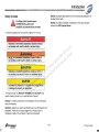
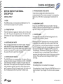
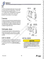
Safety Symbols
0
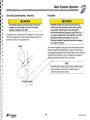
Section 3 contains descriptions of all the controls and indicators on
the dash of the helm.
A
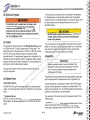
The Safety Alert Symbol means
. . . ATTENTION! Be alert to the
possibility of personal injury or death.
Section 4 contains principles of operation for the major systems
onboard the 420 Express Series.
The following precautions are used throughout this manual.
A DANGER
Indicates an imminently hazardous situation which, if
not avoided, will result in death or serious injury.
m
u
r
o
F
A ,WARNING
s
er .com
Indicates a potentially hazardous situation which, if
n
w um
not avoided, could result in death or serious Injury.
O
s
r
r
o
e
F
s
s
i
r
A CAUTION
u
e
r
C wn
Indicates a potentially hazardous situation, which, if
m
O
not avoided, may result in minor or moderate injury. o
s
r
r
f
e
d
s
i
e
u
d .Cr
CAUTION
a
o
l might result
Indicates the presence of a hazard which
w
n
w
w
in damage to property or equipment.
o //w
D
:
The 'signal words· of DANGER, WARNING
and CAUTION have
p
t
t
specific meaning to alert you to relativehlevel of hazard.
Section 1 contains a description of the Skipper's Kit and information
about the warranty,
Section 2 contains your yacht specifications such as dimensions and
capacities. There are also layout diagrams to introduce you to
floorplans as well as the locations of various components.
~Cruisers
yachts
1-3
420 Express Series
Owner's Manuals for Onboard Systems and
Components
Spend some time becoming familiar with all the information contained
in the Skipper's Kit. Besides containing separate warranty information,
the kit also contains literature which provides important safety
information, operating and maintenance instructions for those
systems and components not manufactured by Cruisers Yachts.
Depending on the options you chose, the kit may contain some or all
of the following literature:
m
u
r
o
F
s
• Engine
er .com
• Hydraulic Steering
n
w um
• RACOR Fuel FilterlWater Separator
O
s
r
• Electric Stove
r
o
e
F
• Battery Charger
s
s
i
r
u
• Water Heater
e
r
C wn
• Trim Tabs
m
• Refrigerator/Freezer
o ersO
r
f
• Generator
d uis
e
• Electric Anchor Windlass
d
r
a
C
• Air ConditionerlHeater
.
o
l
w
n
• Stereo System
w
w
• Compass
Do p://w
• Microwave
t
• Marine Toilet
t
h
• Fire Suppression System
•
•
•
•
•
•
•
•
•
•
•
Carbon Monoxide (CO) Detector
Ice Maker
Propeller Shaft
Shaft Logs
Bow Thruster
Oil Exchange System
Central Vacuum
Search Light Operation
Television, DVD Player, FM Radio
Coffee Maker
Telephone Wiring, Jack and Dockside Receptacle
...
,....
cC
Introduction
J
~
5. Cruisers Yachts recommends that you refer to your engine
warranty for initial inspection and service requirements.
WARRANTY INFORMATION
Warranties for onboard systems and components furnished by
suppliers other than Cruisers Yachts are located inside the Skipper's
Kit. Your Cruisers Yachts Dealer will go through these with you. It is
your responsibility to fill out any warranty registration that may be
required.
6. Perform or provide for the appropriate periodic maintenance
outlined in the owner's manuals and service guides.
Warranty Service
You are entitled to all the benefits and services set down in the
warranties. If a problem arises with your 420 Express Series as a
result of workmanship or materials, contact your Cruisers Yachts
Dealer as soon as possible. Please have your hull identification
number and necessary model numbers on hand for the items that
may need service or repair. Your hull identification number is located
below the rub rail on the starboard side of the transom.
The warranty provided by Cruisers Yachts is printed on the last page
of this manual. You and the Cruisers Yachts Dealer have certain
responsibilities to fulfill to keep the warranty in force.
m
u
r
o
F
1. The dealer will discuss the terms of all warranties and stress the
s
er .com
importance of registering warranties with the appropriate
n
w um
manufacturers.
O
s
r
r
2. The dealer will provide instruction for obtaining warranty service.
o
e
F
s
s
3. The dealer will go over the predelivery service record with you and ui
r
e
r
then sign it to certify that all work has been accomplished.
C wn
m
4. The dealer will provide you with thorough instructions in the
ro ersO
f
operation of your yacht and all its systems.
d uis
e
d
r
a
Your Responsibilities
C
.
o
l
w
n
1. Sit down with the dealer and go over all
warranties.
Fill in the
w
w
w
Cruisers Yachts Limited WarrantyoRegistration
card
which
is
/
D
/
located inside the Skipper's Kit. Keep a record
p: of the hull number
t
for future reference.
t
h
Dealership Responsibilities
r
r
rr
2. Inspect the boat at the time of delivery to ensure that all systems
are operating properly.
3. Sit down with the dealer and go over the predelivery service
record . Sign this record to indicate that it has been explained to
you.
4. Operate all equipment per the manufacturer's instructions.
r
r
1-5
420 Express Series
Section 1
'-"'"
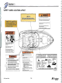
SAFETY LABEL LOCATION LAYOUT
A. WARNING
ACAUTION
Catbon rnano~lde can cauu bf;,il'ld.m ~ g. or duth.
TO PREVENT EXHAUST FUMES FROM ENTERING CABIN,
KEEP ClOSED WHEN ENGINE OR GENERATOR ARE RUNNING.
GHoIine 'ngil1!s Ind generators product ulbcn mono.id,.
Propft' vtnljlali~n un prevent Ulrbon monolili. buOldll~.
WARNING ••• bodily contact with ...vlng
outdrive parts ClIn b. hazlrdous.
Use dool1,lnt'Ms 11\11 ports 10 ere~1t prop'r n~ thlough
venWllion 01 ItUIlIl!.
Do
nol usa swim platform Dr lower ladder
when engine Is running.
Si9"s 01 carbo n monoxide poisoning Includl nJU5U,
diUltllSs and drowslnlf$.$.
Set owner's manual lor mol' inlotJNtlclII.
m
u
r
o
F
s
er .com
n
w um
O
s
r
r
o
e
F
s
s
i
r
u
e
r
C wn
m
ro ersO
f
d uis
e
d
r
a
C
.
o
l
w
n
w
w
Do p://w
htt
It I. 1/169111 for ,ny v.ss.1 10 dump
pl;utic trlt.h .,..,."".,. in thlt Ol:. . n or
nttv/gltb/It w.t.t. 01 th. Unit.d St"I'lI.
AnnltK V of Ih. MARPOL TREATY I • • n
To mlnlmlze sttock flra hazurds:
11)
,
1\nI aft the bc*'• .t\ora connection IIWItch IMfore
connect"'g or dlaconnectlng.~ cabl.,
(2)
Connect IIhore power cab""U. be*: flrat.
(3)
It pohutty wamlng indl(:lltor 'S ecttvnId,lmmedlatBIy
dl&eannect cable and correct po ....tty.
(')
DllICOnnect.nor.pcrwer cable at shot. out.. ftl'llL
(li)
Ck)H aho..po'III'W In.' coy.r tightly.
DO NOT ALTER SHORE·POWER CABLE CONNECTORS
~u~d
l..l.ltJ.1..miI
u.o In thou Ioc.nkon.
....5 . lekfl, Rivar...
s.n.
• Os>t~t!IIg oI11 _II'fMIc,1I'hl1o .["pp~
• Runnlll~wilha ~lg/I boo<at>g"'_
• U.itI; CJo~.u lI.p.... l ido CVfUlIIt 'nd b'I~ rurt>ll'la.
• Operio~"V ... gln" "'~.on In fOtI~nfCIlp..t'•• '"
6odo,&ldc.
• 8Ioc-.Jng cl hull e"""" 0u!\tQ.
• C_~ng WllI>., to~ ... weft u hoaa..>ndl"""'onIfI9~
......... <!lu!n ....
Sou nd. ltnd
bz
~
I/.LEGAL TO OUMP
Pintle
Dunnll9., lInino & p ~ckinll
m.I ""'.I, Ih. 1 lJoa!. algo if
InTltrnltJonlJI L,w fot , cl .. n." u/.,
mIJrJn • • nvironm"u. Vlol.t/on of th.n
t.qulrltm ltnu m,,, ,,,ult In civil pltn.'ty
up to $25,001), fin • • nd Imprlsonm.nt .
o.u.idtr...25...mi/.a.1
.l1...1n..lS.mlG
IllEGAL TO DUMP
PIntle
Dunll.~,lInlng &
,,""tlng m.tvrlals
ILLEGAL TO DUMP
""'"
. .
mile, !com shore
Ihlt floal
ILLEGAL TO OUMP"
1"101 grourod 10 IIlH than
PI..n.= .Gltfbl!ICI
Ofl,lneh:
~
Pa""r
Mvla!
Pa p e r C r oe~ltry
Rl go -"'.C. oo;lary
1'1 111'
Mela!
_Glesi. _!?"ii1lmtg'- QI3Sll~~Od -Food
_
_
_ _.............
J
•
~
---St818.nil loeal regula110ns ma." furthel restnct ItllHtispowof giI.bllla
~;;.:;-_ _
400 LABEL LOC
420 Express Series
1-6
~CruiS9rs
yachts
Section 2
Model Specific Information
m
u
r
Specifications.... .......... .... .. ........... ........... ...................... 2-3
Diesel Engine General
Layout...................... .. ........... 2-23
Fo Fittings
Diesel Fuelrs
Tank and m
..................................... 2-29
Deck Hardware General Layout.............. ........ ...... .. ..... 2-4
e
o
Interior General Layout ........................... .. .................... 2-7
Forward
c Bulkhead (Diesel)......... ....... 2-33
n Engine
.Room
w
m
Oil
Exchange
Layout
... ........ .............. ......................... 2-34
Cockpit Light Plan Layout.. ........................................... 2-9
O
u
s
r
r
Interior Light Plan Layout ......................... ..... ............ 2-10
Room Bulkhead (IPS) .......... .......... . 2-35
oEngine
e Forward
F
s
AlC Plan View .. ..... ..... .................................... ............... 2-13uis
Generator
Layout.......
...... ......... ... .............. ....... ..... ... .. 2-36
r
e
r
Starboard AlC View and Port AlC View ...................... 2-14
nEngine Room Electrical Panels - Yanmar Diesel .... . 2-39
C
Head Ventilation ......... ..................................................
2-15 Ow Fresh Water Layout ... .... .......................................... .... 2-40
m
s Waste Layout w/Macerator ..... ...................... .. ............ 2-43
r...o........ 2-16
r
Plumbing Hardware .. .. ........ ..............................
f
e
d ............
is2-19
Gas Layout - With Return .... ...................e
........
Bilge Pump Layout.. .. ... ............................................... 2-45
u
d
r
Gas Layout - Without Return ............
a.. .. .... .................
Lifting and Storing Your Boat ...... .. ............................ 2-47
C 2-21
.
o
l
w
wn /ww
o
D p:/
htt
~Cruisers
yachts
2-1
420 Express Series
Model Specific Information
SPECIFICATIONS
Measurements
(US I Metric)
L.OA Hull ....... .. .............................................................. 39·0" 111 .9 m
L.O.A. Hull with Integrated Pulpit.. .. .. .... ....... ...... ...... ......... 43" 113.1 m
Beam ..... ................ .... .. .. ....... .... .... .. .. .. ... ........ .... .......... ..... 13·6" 14.1 m
Approximate Weight". Diesel Engines ........... .. . 23.500 Ibs 1 10.659 kg
Approximate Weight*. Gas Engines .................... 22.000 Ibs 1 9.979 kg
Fuel Capacity .............. .... ...................... ............... .. .... . 300 gal / 1136 L
Water System Capacity ................................. .......... ....... 80 gal l 303 L
Holding Tank Capacity ......................................... .... ....... 50 gal / 189 L
Cabin Headroom (minimum) ............................ ....... ............ 6·5" 12.0 m
Height - Keel to Top of Windshield ............ ....... ..... ............ 15·0" 14.6 m
Height - Keel to Top of Arch ................. .................. ........... 14'5" I 4.4 m
Draft ................................................ ...... .......... .. .. ................ 36" 191 cm
Bridge Clearance with Arch .......... ............................. ....... 11·5" 13.5 m
Sleeping Accommodations ................................................. .. 4 persons
m
u
r
o
F
s
er .com
n
w um
O
s
r
r
o
e
F
s
s
i
r
*Weights are estimates and can vary from options and equipment added.
u
e
r
C wn
Engines
m
ro ersO Diesel:
f
Gas:
d uis
e
d
MerCruiser
r
Volvo
a
C
.
o
l
T 8.1 S HO. 420 HP (313 KW). FWC n
w
T TAM074L. 430 HP (321 KW). Electronic Controls. FWC
w
T 8.1 S Horizon. 370 HP (276 KW)w
. FWC
T 06. 370 HP (276 KW). Electronic Controls. FWC
o //w
D
06.310 HP (231 KW) . IPS
:
Volvo
p
06. 370 HP (276 KW). IPS
t
T 8.1 Gi. 375 HP (280 KW). FWC
ht
Yanmar
T 8.1 GXi. 420 HP (313 KW). FWC
T 6LY2A-STp, 440 HP (328 KW) . Electronic Controls. FWC
T 6LYA-STp, 370 HP (276 KW) . Electronic Controls. FWC
~Cruisers
yachts
2-3
420 Express Series
Model Specific Information
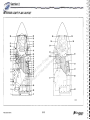
DECK HARDWARE GENERAL LAYOUT - PARTS LIST
1. Windlass Kit
2. Windlass Handle
3. Chain Snubber
4. Cleat
5. Windlass IN Foot Pad
6. Windlass OUT Foot Pad
7. Cleat
8. Navigation Lights
9. Bow Roller
10. Round Hatch
11. Dual Air Horn
12. Courtesy Lights
13. Cockpit Insert, Bottle Storage Top
14. Hand Rail
15. Module Switch Box
16. Cockpit Shower System
17. Faucet
18. Grab Rail
19. Refrigerator/Freezer with Icemaker
20. Wetbar Insert
21. Wetbar Insert
22. Wetbar Insert
23. Fuel Fill Deck Plate
24. Wetbar Insert
25. Wiper Kit Motor
26. Wiper Kit Motor
27. Windshield Stand-Off
28. Swim Ladder and Hatch
m
u
r
o
F
s
er .com
n
w um
O
s
r
r
o
e
F
s
s
i
r
u
e
r
C wn
m
ro ersO
f
d uis
e
d
r
a
C
.
o
l
w
n
w
w
Do p://w
htt
~Cruisers
yachrs
2-5
420 Express Series
d
Section 2
DECK HARDWARE GENERAL LAYOUT
c
c
-:-2-:1l
c
8
. ~- <~:...,,~
"" 9
I ~ -',
:
I
-.
~~~' .
'
-
- ,,>"
"
~
,
./
''X
-
m
u
r
o
F
s
er .com
n
w um
O
s
r
r
o
e
F
s
s
i
r
u
e
r
C wn
m
ro ersO
f
d uis
e
d
r
a
C
.
o
l
w
n
w
w
Do p://w
htt
.-
f
I'
1-
i
..-
,)
/ 0"
....9;
,/
,
'~Y~
" /'
y< -: " .'
I' ~:::"'/
17
20
-
21 22
c:
C '
t:'
C
C
e
WETBAR AREA HARDWARE
5
7
ROPE LOCKER HARDWARE
7
400-10. 1
420 Express Series
2-4
~CruiS8rs
yschts
r
cd
Model Specific Information
DECK HARDWARE GENERAL LAYOUT - PARTS LIST
1. Windlass Kit
2. Windlass Handle
3. Chain Snubber
4. Cleat
5. Windlass IN Foot Pad
6. Windlass OUT Foot Pad
7. Cleat
8. Navigation Lights
9. Bow Roller
10. Round Hatch
11 . Dual Air Horn
12. Courtesy Lights
13. Cockpit Insert, Bottle Storage Top
14. Hand Rail
15. Module Switch Box
16. Cockpit Shower System
17. Faucet
18. Grab Rail
19. Refrigerator/Freezer with Icemaker
20. Wetbar Insert
21. Wetbar Insert
22. Wetbar Insert
23. Fuel Fill Deck Plate
24. Wetbar Insert
25. Wiper Kit Motor
26. Wiper Kit Motor
27. Windshield Stand-Off
28. Swim Ladder and Hatch
m
u
r
o
F
s
er .com
n
w um
O
s
r
r
o
e
F
s
s
i
r
u
e
r
C wn
m
ro ersO
f
d uis
e
d
r
a
C
.
o
l
w
n
w
w
Do p://w
htt
~CruiS9rs
~
2-5
420 Express Series
Section 2
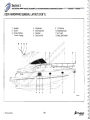
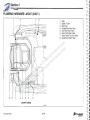
DECK HARDWARE GENERAL LAYOUT (CON'T.)
1.
2.
3.
4.
Spotlight
Anchor
Privacy Porthole
Opening Portlight
5.
6.
7.
8.
Windshield
Bow Pulpit Rail
Bow Rail
Bow End Rail
9. TV Antenna
10. Head Mast Light
11. Arch Light
12. Mast Light Bracket
m
u
r
o
F
s
er .com
7
8
n
w
m
O oru
s
r
se rsF
i
u
e
r
n
C
w
m
O
o
s
fr iser
d
e
u
d
r
a
C
.
lo
w
n
w /ww
o
D p:/
htt
4
4
3
4
3
6
1
2
400·10.3
~
~
420 Exp ress Series
2·6
~Cr'f!,!fgr:.s
c.J
V
Model Specific Information
~
INTERIOR GENERAL LAYOUT
1.
2.
3.
4.
5.
6.
.~-
--
-
. / _--'
(
I
I
\i
\
m
u
r
o
F
s
er .com
n
w um
O
s
r
r
o
e
F
s
s
i
r
u
e
r
C wn
m
ro ersO
f
d uis
e
d
r
a
C
.
o
l
w
n
w
w
Do p://w
htt
Port Closet
Starboard Closet
Towel Ring
Tissue Holder
Stool
Towel Bar
"-
"-
,,
)
/
,"
/"
. "::;.,"
..--.
2
~Crulsers
yachts
2-7
400-10.13
420 Express Series
.1
Section 2
INTERIOR GENERAL LAYOUT (CON'T.)
3
11
m
u
r
o
F
s
er .com
n
w um
O
s
r
r
o
e
F
s
s
i
r
u
e
r
C wn
m
o ersO
r
1. LCD TV
f
3
3
3
d
s
2.
Theater System
i
e
u
d
3.
Surround Sound Speakers
r
a
C
.
o
4.
Surround Sound Subwoofer
l
w
n
5.
Sharp 13' LCD TV
w /ww
o
6. DVD Player
D p:/
7. Refrigerator
t
8. Microwave
ht
9. Stove
9
10. Coffee Maker
11. Fireboy Alarm
5
420 Express Series
2
4(XU.1
2-8
:;Cruisers
yachts
Model Specific Information
COCKPIT LIGHT PLAN LAYOUT
m
u
r
o
F
s
er .com
n
w um
O
s
r w-,--+H!-- 6
r
o
e
F
s
s
i
r
u
e
r
C wn
m
ro ersO
f
d uis
e
d
r
a
C
.
o
l
w
n
w
w
Do p://w
htt
~Crulsers
yachts
2-9
1.
2.
3.
4.
5.
6.
7.
8.
Courtesy Lights
Module Switch Box
Dual Receptacle Box
Dual Receptacle Box
Module Switch Box
Dual Receptacle Box
Dual Receptacle Box
Courtesy Lights
420 Express Series
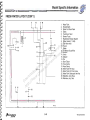
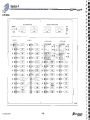
INTERIOR LIGHT PLAN LAYOUT
26
27
29
10
25
30
9
23
7
6
5
4
3
2
26
22
27
21
20
36
m
u
34
r
o
F
s
r com
19
e
33
n
.
25
w
m
32sO
u
18
r
r
o
17
e
F
s
s
i
16
r
u
e
r
15
C wn
24
m
24
ro ersO
f
14
s
i
13ed
u
d
r
a 1227 .C
o
l
(..
w
31
n
w
w
Do p://w
28
I
htt
29
-.
~
/
'0
I --
0
1
35
35
~' -
;,J
33
37
37
35
nil
o
.-
-
--
,. ~
-0 '
0
-.-.-. .
..
~-
34
0
t _rI
.-.I
~-
11
t:..1
400 -6.3
t:_ •
~
-_.1
CI
420 Express Series
2-10
~CrUi~rS
ya is
C
.
-.
C.J
r--
Model Speci'fic Information
INTERIOR LIGHT PLAN LAYOUT - PARTS LIST
1. Dual Receptacle Box
2. Light Switch
3. Dual Receptacle Box
4. Phone Receptacle
5. GFCI Dual Receptacle Box
6. Dual Receptacle Box
7. Light Switch
8. Fluorescent Light
9. GFCI Dual Receptacle Box
10. Dual Receptacle Box
11 . Dual Receptacle Box
12. Light Switch
13. Dual Receptacle Box
14. Dual Receptacle Box
15. Dual Receptacle Box
16. GFCI Dual Receptacle Box
17. Light Switch
18. Dual Receptacle Box
19. Dual Receptacle Box
20. GFCI Dual Receptacle Box
21 . Light Switch
22. Light Switch
23. Fluorescent Light
24. Fluorescent Light
25. Closet Light
26. Reading Light
27. Rope Lighting
28. Overhead Light
29. Carbon Monoxide Detector
30. Head Vent
31. Overhead Light
32. Flourescent Light
33. Closet Light
34. Carbon Monoxide Detector
35. Rope Lighting
36. Reading Light
37. Flourescent Light
m
u
r
o
F
s
er .com
n
w um
O
s
r
r
o
e
F
s
s
i
r
u
e
r
C wn
m
ro ersO
f
d uis
e
d
r
a
C
.
o
l
w
n
w
w
Do p://w
htt
2-11
420 Express Se ries
Section 2
INTERIOR LIGHT PLAN LAYOUT (CON'T.)
21
22
20
19 18 17
16
15
1. Light Switch
2. Light Switch
3. GFCI Dual Receptacle Box
4. Dual Receptacle Box
5. Dual Receptacle Box
6. Dual Receptacle Box
7. Dual Receptacle Box
8. Light Switch
9. Dual Receptacle Box
10. Dual Receptacle Box
11 . Light Switch
12. Dual Receptacle Box
13. Dual Receptacle Box
14. Light Switch
15. Dual Receptacle Box
16. Dual Receptacle Box
17. Light Switch
18. GFCI Dual Receptacle Box
19. Phone Receptacle
20. Dual Receptacle Box
21. Light Switch
22. Dual Receptacle Box
14
13
._--- -
---
m
u
r
o
F
-=",
s
er .com
W-si;==±\-----'
n
w um
- -'il
ii"
O
- " -,
s
r
r
o
! II "
e
F
s
. . - -. -L\
s
i
r
u
e
r
':1j ;
:!
I
'-_ __ _ _ _,00 - ,
C wn
00 ,,'
m
:I\-,__ =- ' ,: '-=_-=--: -~~~ __ ,--:= - -, ,::,,::=::,~ , \
ro ersO .'
f
Iii III
r---- i~--- -- ;r 'Ii_;::'" ,d',\ ed ruis
~, '
'+ ---- + -- '-, n'l-oa w.C
w /ww
o
D p:/
3
tt 7 6 5
12
11
10 h 9 8
4
\
,r'" 1,"".
i;
, ,,-
; /
I
- '."'-
1. ,--- -
-
. .. .:-
f'
'<'
1
,-'--.'·1 ,
1, - - • I '
11 I II
I,
,
:
~.
_
_
_ _
~. _
I ,
--,.
; I
i
"'.- -:
j
__ .__
"
-
-
_
_ •
. •
1
1
2
::J
~
....
~
....
C;
C-~
420 Express Series
2-12
Model Specific Information ~
Ale PLAN VIEW
6
3
5
1
14
12
8
7
9
4
14
m
u
r
o
F
s
er .com
n
w um
O
s
r
r
o
e
F
s
s
i
r
u
e
r
C wn
m
-,~,- --=---=---=---=---~------- ' I> ~
" f-;...
ro- \\i':i':'~;-e<}.~\\\rsO
,~
d u\c",,"':
is e
d
r
a il --.C
Ir====l==--=-=T:o
l
w
n
w
J _ ___ _
w
Do p://w
htt
i
I,
'"
/
/- - -,
-
1
I
0
\ 0
,
- -- - - -,
","
!
-- - -~
15 11 13
1,
2,
3.
4,
5.
Air Conditioner
Air Conditioner
Aft NC Unit Aft Plenum
Aft NC Unit Forward Plenum
Aft NC Unit to Aft NC Plenum
~Cruisers
yachts
/
,
2
10
.
15
6. Aft NC Plenum to Aft Salon
7. Aft NC Plenum to Forward NC Plenum
8. Forward NC Plenum to SalonfTV
9. Forward NC Plenum to Head
10. Forward NC Unit to FSR
2-13
400·1].3
11. Forward NC Unit to Galley
12. NC Grill
13. NC Grill
14. Black Round NC Vent
15. NC Grill
420 Express Series
V
Section2
~
STARBOARD AlC VIEW AND PORT AlC VIEW
\
1.
2.
3.
4.
5.
6.
7.
8.
9
_.
.,
- ---- - - - ' -.
" ',
m
u
r
o
F
s
r com
e
n
.
w
m
O oru
s
r
7 6 1 3
4 10
8
se rsF
i
u
e
r
n
C
w
m
O
o
s
14 11 5 14 12
fr iser
d
e
u
d
r
a
C
.
lo
w
n
w /ww
o
D p:/
htt
-.- - - - - - - -
-
PORT PROFILE
STBD PROFILE
420 E,;press Series
Air Conditioner
Air Conditioner
Aft AlC Unit Aft Plenum
Aft AlC Unit Forward Plenum
Forward AlC Unit Plenum
Aft AlC Unit to Aft AlC Plenum
Aft AlC Plenum to Aft Salon
Aft AlC Plenum to Forward NC
Plenum
9. Forward AlC Plenum to SalonfTV
10. Forward AlC Plenum to Head
11. Forward AlC Unit to FSR
12. Forward AlC Unit to Galley
13. AlC Grill
14. AlC Grill
2
13
2-14
Model Specific Information
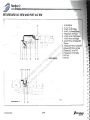
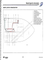
HEAD VENTILATION
2
-- - --
-- T
- .'_ .
-
{
-1/
/
I ·
,
'-'-
(
,
,.
-
r:-
I
;
i
-
- - ~ .-:
i 1
i
f--
i
,J
\
f.
'n
11) 1
/
I
,I,
J
t
,
-,
Vl=
1.
.-
4
3
Inline Blower
Hose Vent
Grill Vent
Vent Hose
-1
m
u
r
o
F
s
er .com
n
w um
O
s
r
r
o
e
F
s
s
i
r
u
e
r
C wn
m
ro ersO
f
d uis
e
d
r
a
C
.
o
l
w
n
w
w
,
Do p://w
1, htt
'v
." - - -- .
!
,
--
1
1.
2.
3.
4.
I,
-
.
---.-- ~
J
400-17.1
:j;CrUisers
yachts
2-15
420 Express Series
::J
Section 2
~
PLUMBING HARDWARE
9
3
5
8
2
m
u
r
o
F
s
er .com
n
w um
O
s
r
r
o
e
F
s
s
i
r
u
e
r
C wn
m
ro ersO
f
d uis
e
d
r 4 1 6 7 3
a
C
.
o
l
w
n
w
w
Do p://w
htt
'\
",
/ /
4QO.13.4
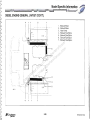
SINK AND SHOWER DRAINS
1.
2.
3.
4.
5.
420 Express Series
Galley Sink
China Sink
Shower Sump Pump
Tee
Head Sink Drain Hose
6.
7.
8.
9.
2-16
Galley Sink Drain Hose
Forward Shower Sump Pump Out Hose
Shower Drain Hose
Aft Shower Sump Pump Out Hose
;;CruiseFS
yachm
I -
Model Specific Information
I
I I -~
PLUMBING HARDWARE LAYOUT (CON'T.)
1.
2.
3.
4.
5.
6.
7.
10
I
14
m
u
r
o
F
s
er .com
n
w um
O
s
r
r
o
e
F
s
s
i
r
u
e
r
C wn
m
ro ersO
f
d uis
e
d
r
a
C
.
o
l
w
n
w
w
Do p://w
~
htt
14 -
[
12 ---8
-5
3
-
Galley Sink
China Sink
Shower Sump Pump
Tee
Head Sink Drain Hose
Galley Sink Drain Hose
Forward Shower Sump
Pump Out Hose
8. Shower Drain Hose
9. Aft Shower Sump Pump
Out Hose
10. Flip Flow wfTrap Drain
11. Barb Trap Drain
12. Thru Hull
13. Sink Drain
14. Hose Clamp
15. Hose Clamp
9
14
1
J
11---1~ ' t
11 --~/1
,
[
4
]
12
-14
3
I
6
14
8
15
13
I
7
SINK AND SHOWER DRAINS
400-13.5,6
~Crulsers
yachts
2-17
420 Express Series
~ Section2
~
PLUMBING HARDWARE LAYOUT (CON'T.)
1
4
1
I
/
6
1.
2.
3.
4.
5.
6.
7.
8.
_ _
v~~
~/ -
- -,
Drain
Spider T-Drain
Sink Drain
Cockpit Sole Drain Hose
Day Hatch Drain Hose
Cabin Entry Drain Hose
Shore Power Tub Drain Hose
Cockpit Sink Drain Hose
m
u
r
o
F
s
er .com
n
w um
O
s
r
r
o
e
F
s
s
i
r
u
e
r
C wn
m
ro ersO
f
d uis
e
d
r
a
C
.
o
l
w
n
w
w
Do p://w
htt
,.
2
3
7
4
5
3
3
8
COCKPIT DRAINS
400-13.8
420 Express Series
2-18
~Cruisers
yachts
Model Specific Information
@
~
GAS LAYOUT - WITH RETURN
1
6
7
1.
2.
3.
4.
5.
6.
7.
8.
3
,
,
t \l
~- -
.
\,
Port Fuel Tank
Starboard Fuel Tank
Generator
Genset Fuel Filter
Fuel Crossover Assembly
Fuel Deck Plate
FueVAir Separator
Flush Vent
m
u
r
o
F
s
er .com
n
w um
O
s
r
r
o
e
F
s
s
i
r
u
e
r
C wn
m
ro ersO
f
d uis
e
d
r
a
C
.
o
l
w
n
w
w
Do p://w
htt
D
\
0
~--""·---~~-~. .~.;;~~=-=~~t~~~~=_~
400-S.10A
6
:;;Cruisers
yachts
4
2
7
2-19
420 Express Series
V
Section 2
GAS LAYOUT - WITH RETURN (CON'T.)
9. Fuel Tank Fill Hose
10. Fuel Tank Vent Hose
11. Port Fuel Tank Feed to Crossover
12. Port Engine Return to Crossover
13. Crossover to Port Fuel Tank Return
14. Starboard Fuel Tank Feed to Crossover
15. Starboard Engine Return to Crossover
16. Starboard Engine Return to Crossover
17. Crossover to Starboard Fuel Tank Return
18. Genset Fuel Filter
19. Fuel Filter to Genset
20. Genset Return to Starboard Fuel Tank
m
u
r
o
F
s
PORT PROFILE
STBD PROFILE
er .com
n
w um
O
s
r8 10 13For 15 25 9
11
9
10 8
e
s
s
i
r
u
e
r
n = = - -= =""
C 1w=
m
ro ersO
f
d uis
e
L_:.J-'
d
r
a
C
.
lo
w
W1;Mry=~--/n
w
w
Do p://w
----'====-=-====I==~
htt
14
I
16 17
420 Express Serres
..
'
400-S.1 1A
12
2-20
~Crulsers
yachts
Model Specific Information
d
~
GAS LAYOUT - WITHOUT RETU RN
1
7
..'//
8
-.----.--.--b--
------
/
/"
"\
.
•
0
•
o 0
'<...
1.
2.
3.
4.
5.
6.
7.
8.
Port Fuel Tank
Starboard Fuel Tank
Generator
Genset Fuel Filter
Fuel Crossover Assembly
Fuel Deck Plate
Fuel/Air Separator
Flush Vent
m
u
r
o
F
s
er .com
n
w um
O
s
r
r
o
e
F
s
s
i
r
u
e
r
C wn
m
ro ersO
f
d uis
e
d
r
a
C
.
o
l
w
n
w
w
Do p://w
htt
f--
o.
-[
2-21
420 Express Series
g
Section 2
GAS LAYOUT - WITHOUT RETURN (CON'T.)
9.
10.
11.
12.
13.
14.
15.
16.
17.
Fuel Tank Fill Hose
Fuel Tank Vent Hose
Port Fuel Tank Feed to Crossover
Port Engine Fuel Filter to Port Engine
Starboard Fuel Tank Feed To Crossover
Starboard Engine Fuel Filter to Starboard Engine
Starboard Fuel Tank to Genset Fuel Filter
Fuel Filter to Genset
Genset Return to Starboard Fuel Tank
m
u
r
o
F
s
er .com
n
wSTBD PROFILE
m
O
u
PORT PROFILE
s
r
r
e rsFo
s
i
18 25
ru ne8 10 14
9
11
10 8
C
m sOw
--~=--I=-I=i ro
f iser
d
e
u
d
r
a
C
---.~~=~~
!
.
lo
w
n
16
w /ww 12
o
D p:/
htt
r
=-~
15
1920
420 Express Series
9
2-22
400-6.116
~Cruisers
yachts
Model Specific Information
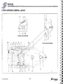
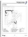
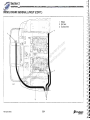
DIESEL ENGINE GENERAL LAYOUT
11
7
10
6
1
,-
2
-- ' --"
1. Port Engine Battery
2. House Battery
3. House Battery
4. Starboard Engine Battery
5. House Battery
6. Port Engine Battery Switch
7. House Battery Switch
8. Starboard Engine Battery Switch
9. House Battery Switch
10. Battery Isolator
11. Trim Tab
~- -- ""'-.'
,--
m
u
r
u
o
F
s
r com
e
ti~ l l ~ i
n
.
"
I_ _
w
i!
m
O oru
s
r
se rsF
Ii"I, ;i,
i
,
u
e
r
n
C
II
w
m
O
o
s
Ii
fr iser
d
d.
e
u
d
r
~
a
C
.
iii
lo
w
n
w /ww
o
D p:/
htt
P7'!
• I
I
", i l , , I
I!:
I
:!
. I
I:
,
~
"
I'
I(- f' -r
II ,
-
L
- ,~
I .
", I -
'
~:i ~
,'", ~ .
~~
' i
~'---- -~-~-G-----iJm-"l
U C-
~--- - I ----
r
r
r:•
5
~Cruiser.s
yschts
9
8
4
4{)G-l0.15
3
2-23
420 Express Series
-v
Section 2
DIESEL ENGINE GENERAL LAYOUT (CON'T.)
!D
!
H
1. Blower
2. Grill Vent
3. Dueting Hose
I
C
1
1
m
u
r
o
F
s
er .com
n
w um
O
s
r
r
o
e
F
s
s
i
r
u
e
r
C wn
m
ro ersO
f
d uis
e
d
r
a
C
.
o
l
w
n
w
w
Do p://w
htt
1
4ooJ.1
2
3
420 Express Series
2-24
~Cruisers
yachts
Model Specific Information
II-- .
I
DIESEL ENGINE GENERAL LAYOUT (CON'T.)
4
1
1
5
1
-----
':-.-/_.-
.'
i
["
r
00
//
,
J
ii
i I
.I
II
r
I
I
I!
I, I,I -, ._-._--___
I
iI
II
--'-'-.
• I
I'
,I
II \ ,- !
----... -
\ \ 1_ ___ _1 '
,\
\I
.\\
,
•
1, Exhaust Elbow
2. Exhaust Elbow
3. Hose Hump
4. Exhaust Tube Splice
5. Exhaust Tube Splice
6 . Exhaust Tube Splice
7. Exhaust Tube Splice
m
u
r
o
F
--6
s
er .com
n
w um
O
s
r
r
o
e
F
s
s
i
r
u
e
r
C wn
m
ro ersO
f
d uis
e
d
r
a
C
.
o
l
w
n
~~:::--3
w
w
o
w
D p://
htt
J:=j- - 3
ii
:
-
•\
\ ':"---~-
400] 3
\
4
(iCru;ssrs
yachrs
1
1
7
2-25
420 Express Series
Model Specific Information
DIESEL ENGINE GENERAL LAYOUT (CaN'T.)
8
1
9
1. Port Fuel Tank
Starboard Fuel Tank
Generator
Fuel Filter
Fuel Filter
Fuel Filter
Fuel Crossover Assembly
Fuel Deck Plate
Fuel/Air Separator
2.
3.
4.
5.
6.
7.
8.
9.
U0
m
u
r
o
F
s
r com
e
n
.
5;,r,==;:r-~~
w
m
O oru
s
r
e rsF
s
i
u
3 ~------~--~~
e
r
n
C
w
m
O
o
s
II i
fr iser
d
e
u
d
r
, 1'- - ·--- --n-l
il f--7
a
C
.
o
l
w
n
w
w
o //w
D
.
p:
t
t
h
;' j
-_._-
i
~
1, \
8
~Crulsers
yachts
6
2
9
2-27
420 Express Series
.V
Section 2
~
DIESEL ENGINE GENERAL LAYOUT (CON'T.)
1.
2.
3.
4.
5.
6.
Scoop Strainer
Thru Hull
Seacock, Ball
Elbow
Adapter
Raw Water Strainer
7. Elbow
8. Adapter
9. Hose Clamp
10. Exhaust Hose
11 . Exhaust Hose
m
u
r
o
F
s
er .com
9
10 7 n
9 8
w um
O
s
r
r
o
e
F
~j
s
s
i
r
u
e
r
5 9
9
n
C
w
m sO
o
r
f iser
d
T---{ l\' J!l=!~,
e
u
,,
d
r
a
C
.
o
l
w
n
w
w
F-3
r=~r~r
'=
Do p://w
9 8
9
2
htt
co
PORT ENGINE INTAKE
~
0
~
10
10
400]6
420 Express Series
STBD ENGINE INTAKE
6
11
•
""'CJi
1
•
~
J
r: .,
J
J
Co
2-26
~Cruisers
yachts
Model Specific Information
V
'="'"
DIESEL ENGINE GENERAL LAYOUT (CON'T.)
1
8
9
-_.-
.
---~----
.---~
"
/
00
. ,
I
-- -
-
1. Port Fuel Tank
2 . Starboard Fuel Tank
3. Generator
4. Fuel Filter
5. Fuel Filter
6. Fuel Filter
7. Fuel Crossover Assembly
8. Fuel Deck Plate
9. FuelfAir Separator
m
u
r
o
F
s
er .com
n
w um
O
s
r
r
o
e
F
s
s
i
r
u
e
r
C wn
m
ro ersO
f
d uis
e
d
r
a
C
.
o
l
w
n
w
w
Do p://w
htt
\
\
\
00
\
. . -"· i---~~~=k=""'--~I
~
4OCL8.10
8
~Cruisers
yachts
6
2
9
2-27
420 Express Series
~ Section 2
~
DIESEL ENGINE GENERAL LAYOUT (CON'T.)
10. Flush Vent
11. Fuel Tank Fill Hose
12. Fuel Tank Vent Hose
13. Port Fuel Tank Feed to Crossover
14. Crossover to Port Engine Fuel Filter
15. Port Engine Fuel Filter to Port Engine
16. Port Engine Return to Crossover
17. Crossover to Port Fuel Tank Return
18. Starboard Fuel Tank Feed to Crossover
/
/
19. Crossover to Starboard Engine Fuel Filter
20. Starboard Engine Fuel Filter to Starboard Engine
21. Starboard Engine Return to Crossover
22. Crossover to Starboard Fuel Tank Return
23. Starboard Fuel Tank To Genset Fuel Filter
24. Fuel Filter to Genset
25. Genset Return to Starboard Fuel Tank
m
u
r
o
F
s
er .com
n
w um
O
s
r
r STBDFoPROFILE
PORT PROFILE
e
s
s
i
r
u
e
r
11
12
18
23 25
n
C
11
13 19 14 1210
w
m sO
o
r
r
f_
~~=--=~= = = = =:
:
r
.
17
e
d
s
i
e
u
d
r
22
a
C
.
o
l
w
n
w
w
21-iH
16
Do p://w
htt
11
/=-:-.=
"I
24 25
20
15
400_6.11
L ,
e:::
t::;
420 Express Series
2-28
~Cruisers
yachts
•
'--'
Model Specific Information ~
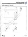
DIESEL FUEL TANK AND FITIINGS
5
1.
2.
3.
4.
5.
1
Starboard and Port Fuel Tanks
Neoprene Gasket
Neoprene Gasket
Mylar Sound Foam
Poly Cleat
m
u
r
o
F
s
er .com
n
w um
O
s
r
r
o
e
F
s
s
i
r
u
e
r
C wn
m
ro ersO
f
d uis
e
d
r
a
C
.
o
l
w
n
w
w
Do p://w
htt
2
3
-..
~Cruisers
yachts
2-29
420 Express Series
<.'
Section 2
.. ,
DIESEL FUEL TANK AND FITTINGS (CON'T.)
5
6
GENSET
RETURN
1
1. Elbow
2. Ball Valve
'=:J r-
3. Adapter
4. Adapter
5. Barb
6. Plug
'4,:;:::>
OJ
~
8
~''$'
t
-
'
~
V
420 Express Series
ENGINE
FEED
GENSET FEED/RETURN
ENGINE RETURN
3
2
-
GENSET
FEED
1
ENGINE FEED
1
m
u
r
o
F
s
.
er .com
n
w um
O
s
r
r
o
e
F
s
s
i
r
u
e
r
C wn
m
ro ersO
f
STARBOARD VIEW
d uis
e
d
r 1
a
C
.
o
l
w
n
w
w
Do p://w
tt
,.,..... h
~"
<-
ENGINE
RETURN
\0
,,).,,:::::=:)
2·30
~
Model Specific Information
I
I.
I
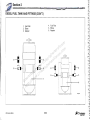
DIESEL FUEL TANK AND FITTINGS (CON'T.)
ENGINE
RETURN
ENGINE
FEED
1.
2.
3.
4.
5.
6.
Elbow
Ball Valve
Adapter
Adapter
Barb
Plug
(/
m
u
r
o
F
s
C=:J
.,
er .com
n
w um
O
s
r
r
o
e
F
s
s
i
r
u
e
r
666
C wn
m
ro ersO
f
d uis
PORT VIEW
e
d
r
a
C
1
.
r-----~l~----~ lo
w
wn /ww
o
D p:/
4
htt
---~
5
ENGINE FEED
1
ENGINE RETURN
1
2-31
420 Express Series
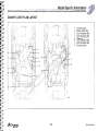
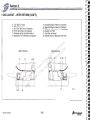
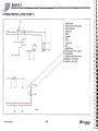
DIESEL FUEL TANK AND FITTINGS (CON'T.)
4. Fuel Filter
5. Elbow
6. Adapter
1. Fuel Filter
2. Elbow
3. Adapter
3
2 --\F
m
u
r
o
F
s
er .com
n
w um
O
s
r
r
o
e
3
F
s
s
i
r
u
e
r
C wn
m
ro 2ersO 6
f
d uis
e
d
r
a
5-+
C
.
o
l
w
wn /ww
o
D p:/
htt
6
5
-i--t----1
---f--j---- 4
--
~
,....,
-
~
420 Express SerIes
2-32
~Cruisers
yachts
Model Specific Information
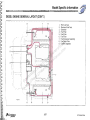
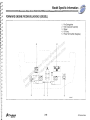
FORWARD ENGINE ROOM BULKHEAD (DIESEL)
1.
2.
3.
4.
5.
Fire Extinguisher
Fuel Crossover Assembly
Blower
Oil Pump
Power Terminal Bar (Negative)
m
u
r
o
F
s
er .com
n
w um
O
s
r
r
o
e
F
s
s
i
r
u
e
r
C wn
m
ro ersO
f
d uis
e
d
r
a
C
.
o
l
w
n
w
w
Do p://w
htt
4
3
2
5
1
._ - - - ,._ --- -.,
/
i
I
I
- ._ --
.'
3
400-1 ().17
.~Cruisers
yachts
2-33
420 Express Series
Section 2
OIL EXCHANGE LAYOUT
2
1.
2.
3.
4.
Oil Pump
Hose, Port Engine
Hose, Starboard Engine
Hose, Genset
5, Hose, Drain Tube
(/
4
ti
Ii
-
I-
f'."
rv '-..,.,...
m
u
r
o
. .
F
s
5
r com
e
t
n
.
I~
w
m
u
I~
3 sO
r
r
o
e
is ersF
Ir~
u
r
C wn
m
ro ersO
1\
f
d uis
e
d
r
I
a
C
rn~~~~~~--DRAIN TUBE
.
o
l
\1
w
I
wn /ww
o
D p:/
\,~\"
htt
U
)
,I
,
~
II
\
,~-
\~
~ -~
1
i--
-j
-'I
--~-
TO PORT ENG
TO STBD ENG
'.
•
'.••...
~-~'
TO PORT GENSET
400·10.21
' II
~ ,.
420 Express Series
2-34
~Cr~f1"
Model Specific Information
U
~
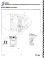
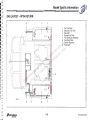
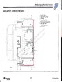
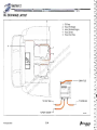
FORWARD ENGINE ROOM BULKHEAD (IPS)
4
2
m
u
r
o
F
s
er .com
n
7 w
m
O
8
u
s
r
r
e rsFo
s
i
ru ne
C
w
m
O
o
s
fr iser
d
e
u
d
r
a
C
.
lo
w
n
w /ww
o
3
D p:/
htt
9
3
19
1. Fire Extinguisher
2. Fuel Crossover Assembly
3. Blower
4. Oil Pump
5. Power Terminal Bar (Negative)
6. Power Terminal Bar (Positive)
.--_ _...., 7. Dash Fuse Block
8. Windlass Fuse Block
9. AC/DC Panel Fuse Block
10. Dash Solenoid
11. Blower Solenoid
12. PME #1 Solenoid
13. Bus Bar Terminal Block
14. PME #1 Module
15. Battery Isolator
16. Battery Switch
17. Battery Switch
18. Battery Switch
19. Battery Charger
18
14
15
17
16
1
12
13
10 5
11
2-35
41·AOOSC
420 Express Series
Section 2
GENERATOR LAYOUT
1.
2.
3.
4.
5.
6.
7.
8.
9.
Round Strainer
Thru Hull
Ball Valve
Elbow
Seawater Strainer
Straight Tail Piece
Water Pickup Hose
Hose Clamp
Generator
m
u
r
o
F
s
er .com
n
w um
O
s
r
r
o
e
F
s
s
i
r
u
e
r
C wn
m
ro ersO
f
d uis
e
d
r
a
C
.
o
l
w
n
w
w
Do p://w
htt
C)
10
I 0
D
420 Express Series
2-36
~Cruisers
yachts
Model Specific Information ~
GENERATOR LAYOUT (CON'T.)
1.
2.
3.
4.
5.
Muffler
Exhaust Hose
Hose Clamp
Exhaust Elbow
Generator
m
u
r
o
F
s
r com
/-----7' I-j-o--------- a~--. -,Il'il
e
n
.
~-=~?='-- -'
• ::' ~', ~~
w
m
,r'/- '" ~'~'
O oru
t--- ------: .
s
r
_._ se rsF
i
:
u
e
r
n
C
3
w
m
O
o
s
fr iser
d
I
e
u
d
r
a
C
.
lo
w
4
n
w
w
Do p://w
ttr--- ----- -I
h
\
I'
',,- ~LJ
3
1
2
I
,'I'
,-
! I
..
'
1'-'
,
\
_
1--
'\1\
- - -- --.- --",-..
~
- .--.- ._-
I
.......
~Cruisers
yachts
----'I \
2·37
5
420 Express Series
V
Section 2
GENERATOR LAYOUT (CON'T.)
4
5
6
7
II!rrn
1. Vented Loop
2 . Hose Clamp
3. Water Heater Hose
4. Elbow
-"
5. Fuel Line Barb
L ______ _____~
6. Hose Clamp
7. Hose
m
u
r
o
F
s
r com
3
i
J'
e
n
.
2
2
w
m
O oru
s
r
se rsF
~
i
u
e
r
n
C
w
m
O
o
s
fr iser
!
d
e
u
-2
d
r
2a
C
.
lo
w
n
•
w /,ww
o
•
'~0
. D.
:/
p
t
ht
,
•
ow- e=
1
G
•
~
'·0·'
·
420 Express Series
,
,
400_9,5
2-38
~CruiS9rs
yachts
•••
';,
r-
··
·
Model Specific Information
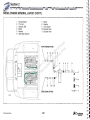
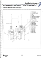
ENGINE ROOM ELECTRICAL PANELS - YANMAR DIESEL
11 -
2
3
1. Engine Room Accessory
Mounting Panel
2. Battery Charger
3. Engine Room Breaker Panel
4. PME #1 Module
5. Accessory Fuse Block
6. Windlass Fuse Block
7. Dash Fuse Block
8. Term inal Bar
9. Terminal Bar
10. Terminal Block
11 . PME #1 Solenoid
12. Blower Solenoid
13. Dash Solenoid
14. Battery Pigtail
15. Fire Extinguisher Control Box
--
-
-
o
_. ®
6 6 6
is 6 i5
m
u
r
o
F
s
er .com
n
w 4um
-t-Irl-O
s
r
r
o
e
F
s
s
i
r
u
e
r
C wn
m
ro ersO~s---I--12
f
© ed
is
u
d
r
a©
C
.
o
l
~3j---13
w
n
w
w
Do p://©w
htt
0
1
5
6
7
~::-:""--'-:;=---+--11
@@@
10
8
9
14
15
400-10. 19
~Cruisers
yachts
2-39
420 Express Series
Section 2
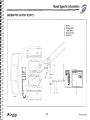
FRESH WATER LAYOUT
1.
2.
3.
4.
5.
6.
7.
Water Tank
Sensor Pump
Water Full Deck Plate
Flushmount Vent
Water Heater (11 Gal)
Washdown Shower System
City Water Inlet
6
5
8. Cold Water Faucet
9. Galley Faucet
10. Shower Mixer
11. Head Unit
12. Head Faucet
13. Head Solenoid
14. Water Tank Fill Hose
15. Water Tank Port Vent Hose
16. Water Tank Starboard Vent Hose
17. Head Water Hose
18. Waterline, Cold, Blue
19. Waterline, Hot, Red
m
u
r
o
F
s
er .com
n
w um
O
s
r
r
o
e
,
F
s
II
s
i
II
-r
u
e
r
C wn
.I~
. ~
m
ro ersO
f
d uis
e
d
r
a
C
.
o
l
w
n
w
w
~~T
II
Do p://w
l
t
t
1;-il-=o.·L
=
'
==
.,
h ,
16 15
4 3 14
2
18
11
17 10
12
I
. i
!
_Li_
7
420 Express Series
19
8
1
13
-
- - - - , --".- ..-
--"
.t.OQ..19.1
9
2-40
~Crulsers
JlSchts
Model Specific Information
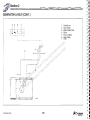
FRESH WATER LAYOUT (CON'T.)
5
3 18
19
l.~ ~L
""
'I'
0. l~
8
15
1> - 01
II>
__ 14
"--17
LJ
13
7
"i
I
,,====:'==
11> ..
I
1. Water Tank
2. Straight Barb
3. Water Full Deck Plate
4. Elbow
5. Flushmount Vent
6. Sensor Pump
7. Washdown Shower System
8. Water Heater (11 Gal)
9. City Water Inlet
10. Faucet
11. Elbow
12. Ice Maker Shutoff Tee
13. Adapter
14. Union
15. Adapter
16. Tee
17. Stem Elbow
18. Hose Clamp
19. Hose Clamp
20. Water Tank Fill Hose
21. Water Tank Port Vent Hose
22. Water Tank Starboard Vent Hose
23. Waterline, Cold, Blue
24. Waterline, Hot, Red
m
u
r
6
o
F
s
13
er .com
2
n
w15 um
O
4
s
r
r
o
e
F
s
s
i
r
u
e
r
C wn
m
ro ersO
22f
d uis
e
d
r
a
C
.
o
l
w
n
w
w
Do p://w
t
t
h
r--- 20
21-
13
...-A
~
~
1
4
9 11
~J
~10
17 ----I
_ _ 12
..
I
T
16
~CrUisers
yachrs
I
2~
400-19.2
d4
2-41
420 Express Series
FRESH WATER LAYOUT (CON'T.)
'f'
J'
1.
2.
3.
4.
5.
6.
7.
i'!
if 1
1--9
11
.. .B
- - - i , ..
•
r=y
5-,.J
r11
6
3
16
420 Express Series
7
m
u
r
o
F
s
r com
e
n
.
4
13
w
m
O oru
s
r
se rsF
i
u
e
r
n
C
w
m
O
o
s
fr iser
d
e
u
d
r
a
C
.
lo
w
n
w /ww
o
D p:/
htt[ f}- a
6
1f'.Ji
14
I
15
1
=
Head Faucet
Galley Faucet with Sprayer
Head Solenoid
Head Unit
Elbow
Adapter
Barb
8. Adapter
9. Shower Kit
10. Tee
11 . Stem Elbow
12. Double Barb PVC Coupler
13. Hose Clamp
14. Techma Head Water Hose
15. Waterline, Cold, Blue
16. Waterline, Hot, Red
"
/
r.-h
a
~
r'
400.19.3
2-42
~Cruisers
yachts
Model Specific Information
V
~
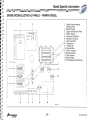
WASTE LAYOUT W/MACERATOR
3 8
7 2
lit
11
9
10
9
-- --.. =--:'1 ~- -~ -:::: -::-::~-'- "'~f: l'-'-:-- :
.- ..--
m
u
r
o
- - jl
F
s
I
i
er .com
n
p=.=======11 i Ow um
r
'
I rs
o
e
F
s
o
i I ers
I
u
r
C wn
~~_=_t=-~~==~~C:'J-'.=l-==-::-i' f::=t:::::::=:::::::===--=-=1-!'
-I'
m
I
I
O
/ ,? I
ro ers
f
I
I
~ :----- a-~ded Crui-s -II Ii,
lo i w.
n
w_:::: ...
w ;.,',-/, w
o
JJD p:/
htt
!-
- -
~
1
1. Waste Tank
2. Flushmount Vent
3. Waste Tank Deck Plate
4. Thru Hull Seacock
5. Macerator Pump
6. Head Unit
7. Waste Tank Vent Hose
8. Waste Tank Pump Out Hose
9. Macerator Pump Out Hose
10. Techma Head to Holding Tank
11. Techma Head Water Hose
12. Techma Head Solenoid
!
. I
--i
I,
I
..
- - -..-,-~
'11, _ .
....
1
1
- - -
I
I
I
:
,
.. - , ' - '
-- _._
- ---
1
~Cruis8rs
yacnts
12
4
5
400-1B.1
2-43
420 Express Series
V
Section2
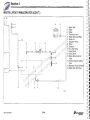
WASTE LAYOUT WIMACERATOR (CON'T.)
4 12
tl =
"i-- 5
6
11
~j
§ - 11
r
13
m
u
r
o
F
s
er .com
n
w um
O
s
r
~tB
r
o
e
F
s
s 10
i
r
u
e
r
C wn1-m
0
ro ersO
f
d uis
e
d
r
a
C
.
o
l
w
n
w
w
CID
Do p://w
11
2
14
htt1
2
11
7
15
."==~~,,L,,~
16 -
8
9
~
~
12 - - 3-
•
1.
2.
3.
4.
5.
6.
Waste Tank
Elbow
Elbow
Flushmount Vent
Waste Tank Deck Plate
Head Unit
7. Macerator Pump
8 . Elbow
9. Seacock
10. Thru Hull Fitting
11. Hose Clamp
12. Hose Clamp
13. Waste Tank Pump Out
Hose
14. Techma Head to Holding
Tank
15. Macerator Pump Out HOSE
16. Waste Tank Vent Hose
~
I
2
1
400-- 18.3
.J
c. J
e.-
e'J
c
420 Express Series
2-44
~Cruisers
yachrs
,I
~
Model Specific Information
-a
~
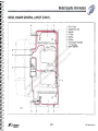
BILGE PUMP LAYOUT
1.
2.
3.
4.
5.
Bilge Pump Bracket
Bilge Pump
Bilge Float Switch
Float Switch Bracket
Bilge High Water Alarm
6.
7.
8.
9.
Bilge Pump Bracket
Forward Bilge Pump Out Hose
Middle Bilge Pump Out Hose
Aft Bilge Pump Out Hose
m
u
r
5
4
3
9
2
8
2 1
o
F
s
er .com
n
w um
O
s
r
r
o
e
F
s
s
i
r
u
e
r
C wn
m
ro ersO
f
d uis
e
d
r
a
C
.
o
l
w
n
w
w
Do p://w
htt
400- 13.1
5 4 3
6
5
4
2
3
2-45
7
1
420 Express Series
V
Section 2
~
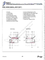
BILGE PUMP LAYOUT (CON'T.)
AFT BILGE PUMP
FWD BILGE PUMP
r,
~
7--
a~
Q
3
3
Q
Q
2
2
Q
1
1
!--a
m
u
r
o
r~
~r
F
s
er .com
n
w u1m
O
. Bilge Pump
s
r
r
o
e
Float Switch
2.
F 3. Bilge
s
s
i
r
Bilge High Water Alarm
u
e
r
n
4. Forward Bilge Pump Out Hose
C
w
5. Middle Bilge Pump Out Hose
m
O
o
s
r
6.
Aft Bilge Pump Out Hose
r
f ise
7. Hose Clamp
d
e
u
8. Thru Hull Fitting
d
r
a
C
.
o
l
w
8~ n
Q
w
w
o
w
Q
D p://
,
htt
r~
,
6
7
,
4
7
MID BILGE PUMP
r,
3
2
1
400-13.2
5
420 Express Se ries
2-46
7
~CruiS8r.s
yachts
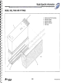
Model Specific Information ~
.............
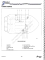
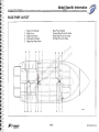
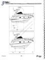
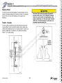
LIFTING AND STORING YOUR BOAT
The shipping/storage-cradle will provide the proper support at the
recommended positions. The load at the cradle support areas is less
than 10 pounds per square inch. Make sure the cradle is level and
completely supported on the ground to eliminate any cradle or hull
distortion. Contact your Cruisers Yachts Dealer to order a cradle.
A CAUTION
DO NOT lift a yacht with a large amount of water in the
bilge! Undue stress will be put on the hull that may
cause damage which Is not covered under the
warranty.
If a factory-supplied cradle is not available, use extreme care to
support the hull as shown. Do not support yacht by resting hull on
keel; the load will be more than 10 pounds per square inch! Vertical
supports must extend from chine to keel to chine with no gaps
between the hull and cradle supports. Protect all items extending from
the hull from resting on the support or ground. DO NOT apply any
load stress to propellers, shafts, rudders, struts or drive systems.
Slings must never contact or exert a force on shafts,
struts or hardware protruding from the hull. This type
of stress can damage fiberglass, bend or misalign
parts, which is not covered under the warranty.
m
u
r
o
F
s
Use two web slings and 13 ft (4 m) to 16 ft (5 m) spreader bars to lift
er .com
the yacht based on the width of your yacht's beam. Refer to
n
wcan notubemused, use foam blocks on the keel and
If a cradle
SPECIFICATIONS. Slings must have a minimum width of six inches
O
s
jackstands
on the
r chine.
and a capacity rating high enough to support the yacht. Spreader bars
r
o
e
F
s
reduce the side pressure at the yacht's sheer line and prevent
sinformation on storing your yacht, refer to STORAGE AND
i For more
r
u
e
r
distortion or damage to the deck or gunwale molding.
n
C wEXTENDED
LAY-UP in Section 8 of the Getting Started manual.
m
O
Put slings around the hull at positions marked "SLING." The
sling
ro ers
decal is located just under the gunwale molding. Make f
sure the sling
d uisin
contacts the bottom of the hull for the entire lengthewith no twists
d
r
a
the sling.
C
.
o
l
w
n
w
When lifting the yacht, keep the boww
slightly higher
than the stern to
o manifold.
w
/
keep water from running into engine
D
/
: Water can cause
corrosion or damage to the engine. tp
ht
A
CAUTION
When your yacht is out of the water, it is important to
support the hull correctly to avoid any hull damage.
~Crujsers
yachts
2-47
420 Express Series
Section 2
m
u
r
o
F
s
1-- er .com
n
w um
O
s
r
r
1-- - - - - - o
e
F
s
s
i
r
u
e
r
C wn
m
ro ersO
f
d uis
e
d
r
a
C
.
o
l
w
n
w
w
Do p://w
htt
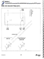
114 112' -
-
..,
(2.91m)
[ --
-
-143118' - - -(3.84m)
400-1G-3a
265112' - - - - - - - -(6.74m)
85' -
--1 r-~---- 180114'
- - ----I
(4.58m)
420 Express Series
2-48
400- 10.3b
Section 3
Controls and Indicators
m
u
r
o
F
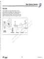
Fuel Gauges........... ........ .................. ............ ... .. .......... .. 3-2
s
m ................... ......................... 3-5
Engine Buzzer ............................................................... 3-2
er ... ................................
Hom
o
c
n
.
Pump .. .................. .. .. ....... ... ........................ 3-5
Depth Finder ............................... .. .. .... ... .............. .......... 3-2
w AftlMidlFwd
m
O
u
Engine Alarm Display..... .. .............. ................ ........... .... 3-2
Port/Starboard
Wiper ... .................................................. 3-5
s
r
r
o
EDC Display........................................................... .. ..... 3-2 se
... ............. .... ........... ........ 3-5
Port/Starboard
Washer
FSpreader/ Engine Room...........
s
i
r
Lights
........
................. .............. 3-5
Searchlight Controls ...................................................... r3-2
u
e
n
C
Stereo Remote ................ .............. ........ ........................ 3-2
Anchor/Nav Lights .......... .... ................................. .... ....... 3-5
w
m
SeaKeyTM Emergency Panel .............. .. .......... ...............
3-2
Cockpit Lights ................................................................ 3-5
O
s
ro e3-2
r
f
12 Volt Accessory Switch Panel .. ...... ............................
Boarding Lights ............. .. ...... ................ ............ .. .. ..... .. .. 3-5
d.... .. .. .... ......
is.... 3-2
Fireboy Alarm ............ ..................... ......
...
Engine Room Fans ................... ..................................... 3-6
e
u
d
r
Dash Breaker Panel... ... ............. a
... ..... ... ....... ........
.........
3-2
Windlass Power .. .. ............ ............................................. 3-6
C ....... 3-3
.
o
l
..
...............
VHF Radio ..............................
...............
Battery Parallel ...... ....... .... .. ..... .. .......... ............... ........ .... 3-6
w
n .....................................
w
w
Volvo Electronic Diesel
Control
3-3
Keyless
Operation .. ................ .......................... .............. 3-6
Do p://w
High Water Alarm ..........................................................
3-3
Engine Ignition Start/Stop .............................................. 3·6
Throttle Controls ..............................
.............................. 3-3
Dim ...... ........... .. ............... ............................................... 3-6
tt
Trim Tab Controls andhIndicators .............................. .. ... 3-3
Keypad ........ ........ .. ....... ................ .. ........ .. ........... ... .. ... .. .. 3·7
Helm Controls (Volvo Diesel) .. .... ........ .. .... ... .. ............. 3-4
Keypad Switch Functional Description ... ............... .. .. . 3-5
Dash Panel Layout ............................... .... ........... ........... 3-2
Compass ..... ........... ..... ... .. ........ .......... ............... ............ 3-3
~Cruisers
yachts
3-1
420 Express Series
U
Section 3
~
DASH PANEL LAYOUT
7 - STEREO REMOTE
This remote control allows the stereo to be controlled from the helm
station. The primary controls for the stereo are located in the galley.
1 - FUEL GAUGES
IMPORTANT
Do not rely on the accuracy of gauges. Readings are only
approximate and should always be compared to the hours
of use multiplied by the known fuel consumption (GPH).
8 - SEAKEYTM EMERGENCY PANEL
See the SeaKey owner's manual that is included in the Skipper's Kit
for a detailed description of the functions.
These gauges indicate the approximate amount of fuel in each tank.
9 -12 VOLT ACCESSORY SWITCH PANEL
m
u
r
o
F
Works in conjunction with the Volvo EDC (Electronic Diesel Control):
s
er .com
an electronically controlled processing system.
n
w um
O
s
r
r ALARM
10 - FIREBOY
o
3 - DEPTH FINDER
e
F
s
shas an indicator lamp to indicate fire suppression
idisplay unit
r
The
u
e
r
nfire extinguisher status. The lamp should glow when the
C automatic
4 - ENGINE ALARM DISPLAY
w
m
switch is in the ON position indicating a charged system.
sO the
Works in conjunction with the Volvo EDC.
ro eignition
r
f
Should
system discharge, the lamp will not glow. Refer to the Fire
d
s
i
Suppression
owner's manual in the Skipper's Kit for complete details.
e
u
d
r
a
C
5 - EDC DISPLAY
.
o
l
w
Monitors and displays engine and boat functions.
11 - DASH BREAKER PANEL
wn /ww
o
D p:/
Circuit breaker panel to reset the accessory designated to the
breaker. Resetting a circuit may not cure a problem. If the circuit
6 - SEARCHLIGHT CONTROLS
htt
continues to trip, refer the problem to your Cruisers Yachts Dealer.
These switches are toggle action switches that control the accessory
designated to the switch. When a switch is pressed, the accessory
power will turn ON. When the opposite end is pressed, the accessory
power will turn OFF.
2 - ENGINE BUZZER
The searchlight is controlled from a joystick.
SELECT S - slow light movement.
A CAUTION
SELECT F - fast light movement.
DO NOT reset a breaker which continues to trip
without first discovering and remedying the cause of
the problem.
DIRECTIONAL MOVEMENT - The joystick is moved left, right,
forward and aft to move the light beam.
420 Express Series
3-2
c.
•
~
II
II
~
c .
c: .II
c...
C...,j
Controls and Indicators
16 - TRIM TAB CONTROLS AND INDICATORS
12 - VHF RADIO
Refer to the VHF Radio owner's manual in the Skipper's Kit for
complete details.
NOTE
Push the trim tab rocker switches in half second bursts.
Holding the rockers down too long will over trim the boat.
13 - VOLVO ELECTRONIC DIESEL CONTROL
The trim tab switches are used to correct the trim of you boat while
you are underway.
See the Volvo Electronic Diesel Control owner's manual that is
included in the Skipper's Kit for a detailed description of the functions.
• To trim the bow of your boat down, push the top halves of both
switches.
• To trim the bow of your boat up, push the bottom halves of both
switches.
14 - HIGH WATER ALARM
m
u
r
oMANEUVERING TECHNIQUES in Section 6
Refer to SUGGESTED
F
s
of the Getting Started
er manual.
om
c
n
.
15 - THROTTLE CONTROLS
w um
O
s
17-COMPASS
r
The throttle control lever for the port engine is the port side lever and
r
o
e
F
s
the throttle control lever for the starboard engine is starboard lever.
s has not been compensated. The compensating should
i The compass
r
e
NEUTRAL is at the center, FORWARD is forward (away from you) ru be performed
compass adjuster. After the compass has
nadjusted,byDOa qualified
C
one detent and REVERSE is aft (toward you) one detent. Gradually
w
been
NOT
allow
any iron or steel objects to be placed in
m
O
o
push forward to go into FORWARD and continue to push forward
to
s
- even temporarily. Refer to the owner's manual included in
fr andiser itsthevicinity
increase engine speed. Gradually pull aft to go into REVERSE
Skipper's Kit for detailed information.
d
e Alwaysrreturn
u
continue to pull toward you to increase engine speed.
d
a
C
the controls to NEUTRAL when the engineslo
are not running.
.
w
n
w /ww
o
D p:/
htt
The alarm will sound when the high water alarm float switch is
activated.
~Cruisers
yachts
3-3
420 Express Series
HELM CONTROLS (VOLVO DIESEL)
4
3 2 1
1 2 3
4
-- - - - -
/-- -.-+---t-:b--±-N_
/
•
5-~A'
m
u
r
o
F
s
er .com
n
6
w um
O
s
r
r
o
e
F
s
s
i
r
u
e
r
C wn
m
ro ersO
...
f
is
9d
e
u
d
r
a
I'
\~,
.C
,- / nlo
w
~' l-- j ./
1/ ow /ww
D p:/
13. Volvo Electronic Diesel Control
Remote
SeaKeyTM Emergency Panel
14. High Water Alarm
htt 7.8. Stereo
--1%---+--- 5
\ .~ .
7
~
@
w __
12
o
10 - - + 0
/
/
1.
2.
3.
4.
5.
6.
.G
Fuel Gauges
Engine Buzzer
Depth Finder
Engine Alarm Display
EDC Display
Search Light Control
420 Express Series
0
0
•••
11
'<
9. 12 Volt Accessory Panel
10. FIREBOY Alarm
11. Dash Breaker Panel
12. VHF Radio
3-4
)
4(XU ·'
15. Throttle Controls
16. Trim Tab Controls
17. Compass
~Cruisers
yachts
Controls and Indicators
5 - SPREADER/ENGINE ROOM LIGHTS
KEYPAD SWITCH FUNCTIONAL
DESCRIPTION
These buttons are toggle action buttons that control the
corresponding lights. When a button is pressed, the corresponding
light(s) will turn ON. When it is pressed again, the light(s) will turn
OFF.
KEYPAD LA YOUT
1- HORN
The HORN button is a momentary button controlling the horn. The
horn will sound as long as the button is pressed.
6 - ANCHOR/NAV LIGHTS
Pressing the ANCHOR/NAV light button turns ON the NAV light.
Pressing it a second time turns the NAV light OFF and the ANCHOR
lights ON. Pressing it a third time turns them both OFF.
m
u
r
o
F
7 - COCKPIT LIGHTS
s
ercan be .controlled
om from the keypad or from the
The cockpit lights
c
n
wsalon umomentary
transom and
switches.
m
O
s
r lights button will turn the cockpit lights ON.
r the FCOCKPIT
o
e
Pressing
s
3 - PORT/STARBOARD WIPER
s button while the lights are ON will start a five minute
r
this
ui Pressing
e
These are toggle action buttons that control the wipers. Pressing a Cr
timer.n
After the five minute time elapses, the lights will automatically
w
button will turn ON a wiper in the low speed mode. Pressing it am
turn
OFF.
Pressing the button while the cockpit lights are in the timer
O
roit a thirders state will turn
second time will turn it ON in the high speed mode. Pressing
f
the lights OFF. If the lights turn OFF due to the five
d
time will turn the wiper OFF and park the wiper. The LEOs
indicateis
if
minutes
elapsing,
and the button is pushed again, the lights will turn
e
u
d
the wiper is ON and the speed mode of the wiper.
r
ON, repeating the cycle. The cockpit lights are also controlled by
a
C
.
o
l
momentary rocker switches that are located at the transom and salon
w
n
w
w
entrances. These switches emulate the keypad COCKPIT lights
w
4 - PORT/STARBOARD WASHER o
/
D
button logic.
/
:
The WASHER button is a momentary action.
The washer will stay on
p
tt is not ON, the WASHER
as long as the button is pressed. If a h
wiper(s)
2 - AFTIMID/FWD PUMP
These three buttons are toggle action buttons, push to turn ON, push
to turn OFF. They control the respective pumps. The indicator LEDs
will illuminate when power is being supplied to the corresponding
pump.
button will energize the wiper in low speed. The system has an offdelay function for the wiper(s) that were energized by the WASHER
button allowing the wiper(s) to stay ON for several cycles and then
park. If a wiper was ON prior to the washer cycle, it will remain on at
its commanded speed both during and after the washer cycle.
~Cruisers
yachts
8 - BOARDING LIGHTS
The boarding lights can be controlled from the keypad.
The boarding lights will toggle ON when the BOARDING button on the
keypad is pressed. They will toggle OFF when the button is pressed
again.
3-5
420 Express Series
~ Section 3
9 - ENGINE ROOM FANS
13 - ENGINE IGNITION START/STOP
This button has a toggle action. Push the button to turn the fans ON,
push it again to turn the fans OFF.
Successfully entering the correct four-digit user code and pressing the
ENTER button will unlock the ignition system. At this point the PORT
and STBD ENGINE IGN buttons are enabled (active). When the
system is unlocked, a 15 minute timer begins. When the 15 minutes
elapses, the system will automatically lock if no further ignition
function buttons are pressed. Pressing either engine ignition button
will toggle the corresponding master engine ignition relay ON, and its
indicator will light.
10 - WINDLASS POWER
The WINDLASS POWER button is a toggle action function . Push the
WINDLASS POWER button to turn windlass power ON. The indicator
will turn ON when windlass power is ON. When the windlass power
indicator is ON, pushing the up or down arrows will cause the
windlass to go up or down.
m
u
r
o
11 - BATTERY PARALLE L
F
s
r com
This is a momentary function that controls the battery parallel
e
n
.
solenoid . When this button is pressed, the battery parallel solenoid is
w
m
energized , connecting the two cranking batteries in parallel. When it is
O oru
s
r
released, the solenoid is de-energized. This function should be used
se rsF
i
only when one of the cranking batteries is not charged sufficiently to
u
e
r
start the corresponding engine.
n
C
w
m
O
o
s
fr iser
12 - KEYLESS OPERATION
d
e
u
d
Security is provided by using a keyless control to enable
engine Cr
a
.
lbyothe ENTER
functions. Key in the four-digit user code followed
w
n
button. The ENTER button also serves as aw
reset button ifw
error is
o
w anbutton
/
made entering the four-digit code. Simply
press the/ENTER
D
and start over.
p:
t
t
h
14 - DIM
The DIM arrows control the light level of the keypad LEDs and backlighting, and other helm lights. Pressing the up arrow will increase the
light level. Pressing the down arrow will decrease the light level.
IMPORTANT
Each key press must be within three seconds of each
other or the keypad will reset.
420 Express Series
3-6
~Cruisers
yachts
Controls and Indicators
KEYPAD
9
1 ---/-----tt-It-
m
u
r
o
13
F
s
er .com
n
w um
10
O
s
r
r
o
e
F
s
s
i
r
u
e
r
C wn
m
ro ersO
f
d uis
e
d
r
a
C
.
o
l
w
n
w
w
Do p://w
htt
-4\-'\\--\--- 11
7
6
~Cruisers
yachts
3-7
KEYPAD
420 Express Series
Section 4
Basic Systems Operation
m
u
r
Power Train ........ ......... .. .......... ..... .................... .. ..... ....... 4-2
Trim Tabs ............
.................. 4-9
o.. .. .. .......................................
F
s
Engines ..... .. .. .. ......... ............... ....... ... ..... .. ...... .. .. ............ .. .. 4-2
.......
..
........
.......
...
...
.........
.... .. 4-1 0
Electrical System.......
r
m
e
o
DC Electrical
System
..
......
..................
........................
...... 4-10
Engine Ignition Starting/Stopping - Key Switch ........ .......... 4-2
c
n m...............................
w
DC
Master Panel
.. .......... ............. ....... 4-11
Engine Ignition Start/Stop - Keypad ................................... 4-3
ODC PanelorCircuit
u Breaker Functions .............. .............. ..... 4-12
s
IPS ................. ....... .... .. ..... ...... ..... ........... .... ........... ..... ....... . 4-4
r
e
F System .............. .......................................... 4-14
Transmission ...... ....... .................. .... ................. ...... ... ......... 4-4
AC s
Electrical
is eAC
r
Shaft Assembly - Inboards...... .......................... .. ........ ....... 4-4ru
Master Panel. ....................... ................... .................... 4-14
C wn AC Panel Circuit Breaker Functions ........ ..... .................... 4-16
Strut and Cutlass Bearing - Inboards ................ ......... ........ 4-5
m
US Stds .............................. .... ............... .. ................ ......... 4-18
Propellers .............................................. ......... ..............
o.... .. 4-5ersO Inti
r
f
Stds 2-30 Amp (220 Volts) .......... .. ................ ......... ..... 4-19
Fuel System (Crossover Valve) ............ .. .............
..
..
...
..
4-7
d
s
i
e
u
............r..... 4-7
Steering System ........... ........... .. ..... ............
d .........
a
C 4-8
.
Steering Wheel ... .......... ......... ..... .........
...........
.............
o
l
w
Rudder - Inboards.. .. .. .... .. ........ ....n
w.. .......... .... .. .. . 4-8
w .... .. ...........
o
w
D p://
htt
~Cruisers
yachrs
4-1
420 Express Series
.0
Section4
~
POWER TRAIN
Each engine is cooled by seawater entering the yacht through a
seacock in the hull bottom. The water enters the engine through the
engine water jacket and is returned to the sea through the exhaust
system.
Engines
Your yacht is powered by twin inboard engines. All operation,
specification and maintenance information is contained in the engine
owner's manual. Find this manual, which is located in the Skipper's
Kit, and familiarize yourself with it. The engine is the heart of your
yacht and following the manufacturer's recommendations will provide
you with continued boating pleasure.
A feature which is standard on diesel engines is the fresh water
cooling system. This system uses the incoming seawater to cool a
secondary closed-cooling system. The seawater flows through an
engine mounted heat exchanger, cools the closed system coolant,
and is returned to the sea via the exhaust system.
m
u
r
o
F
s
r com
e
n
. specified limits
• Engine temperature exceeds
w
m
• Engine s
oilO
pressure drops
specified limits
u belowexceeds
IPS ENGINES
r
r
o
• Transmission
oil
temperature
specified limits
e
F
s
The IPS (Integrated Propulsion System) is a fully integrated
s
i
Ignition switches
r are ON, engines are OFF
e
rTo•utest
propulsion system. The controls, propulsion, rudder and steering
n
C
the alarm system, turn the ignition switch to the ON position.
w upon the engine, the alarm may sound immediately, or
system are all integrated. The engine's power is transferred through m
Depending
O
o
s
the hull and into the IPS.
r a few seconds delay.
fr iseafter
d
e
u
d
r
COOLING SYSTEM
a
C
.
lo
Engine Ignition Starting/Stopping - Key Switch
w
n
w
CAUTION ow
Your Cruisers Yacht may be equipped with key switch STARTING/
Dcoolingp:water
//w
The cooling system starts at the
STOPPING switches. This type switch works on the same principle as
t
seacock. which can be shut off for atnumber
of
an automobile. Refer to the Engine owner's manual in the Skipper's
reasons. Make sure the seacocks h
are open before
Kit for complete details.
INBOARDS
ALARM SYSTEMS
The power generated by the engine is transmitted to the propeller via
the transmission, shaft coupling, and the propeller shaft assembly.
The propeller shaft is supported and aligned with the engine by a
throughhull shaft log and an outside strut.
Alarm systems are on all boats. The alarm will sound under the
following conditions:
starting engines. The absence of cooling water will
cause the engines to overheat and cause irreparable
damage.
420 Express Serles
4-2
~Crujsers
yachts
Basic Systems Operation
Engine Ignition Start/Stop - Keypad
The system can be locked, only if the engines are OFF, by entering
either the user code or the master codes correctly and pressing the
ENTER button. The system will automatically lock after the 15 minute
time out period, if no engine rotation occurs. The engine ignition
circuits that are ON at this time will automatically be turned OFF.
Successfully entering the correct keyless code then pressing the
ENTER button will unlock the system. At this point the PORT ENGINE
IGN and STSD ENGINE IGN buttons are enabled. When the system
is unlocked, a 15 minute timer begins. If the system senses that either
or both engines are running or rotating during the 15 minute period,
the timer is reset and turned OFF. If neither engine starts during the
15 minute period, the system will lock. It will then be necessary to reenter the user code to unlock the system and enable starting the
engines.
REPROGRAMMING THE USER CODE
The following is a description of how to program/reprogram the fourdigit user code.
m
u
r
1, will blink approximately twice a second,
the LED, adjacentF
too
s
r
moff.
otherwise the
LED
will
remain
e
o
c
n
.
3. Type inw
the new four-digit code, first to enter the code then to
m the ENTER button in between. Example: If
O
u
verify,
without pressing
s
r
r
o is 1, 2, 3, 4 then the user will type in 1, 2, 3, 4, 1,
code
ethe desired
F
s
s
i
correctly when pressing the final verification digit
e4.rIf done
ru 2,then3,system
C
will unlock and the unlock LED will remain illuminated.
wCaution: Each key press must be within three seconds of each
If an ENGINE START indicator is ON the corresponding ENGINE
m
O
o
s
START button is enabled. The ENGINE START indicator will
fr light iser other or the keypad will reset.
d
when the engine tachometer signal is sensed, indicating
engine
enot indicate
u
d
r
rotation. It is important to note that the indicatora
does
C
. shaft
o that thewcrank
when the engine is successfully started but simply
l
n
is rotating. The indicator will remain ONw
as long as the
is
wsystem
o
w
receiving the signal from the engine
tachometer.
At
this
point
the
15
/
D
/
:
minute timer and further actuation of the engine
button is
pas longignition
t
t
disabled. The 15 minute timer is disabled
as
one
or both
h
1. Type in your four-digit code. Caution: DO NOT press ENTER.
With the system unlocked, pressing either ENGINE START button will
toggle the corresponding master engine ignition circuit ON, and the
corresponding indicator will light. The 15 minute counter is reset each
time one of the six buttons which control the engine ignition is
pressed. When the 15 minute time elapses and the tachometer inputs
are not detecting button activity or an engine running, the system will
automatically turn the master ignition circuits OFF and lock the
system.
2. Simultaneously press 1 and 4. If the code was entered correctly,
engines are running. If both engines are not running and none of the
ENGINE START/ IGN buttons are pressed, the timer is restarted and
the system will lock when the 15 minute time elapses.
When an engine is running, pressing and holding the ENGINE STOP
button will turn the corresponding master engine ignition OFF. The
ENGINE STOP button is a momentary button and needs to be held in
until the engine is stopped.
~Cruisers
yachts
4-3
420 Express Series
Section 4
IPS
SHAFT LOG
The IPS is a fully integrated propulsion system. The engine is located
in the yacht (inboard) and the propulsion system, on the hull. Power
from the engine is sent through the hull into the transmission and then
into the propulsion system. The steering system turns the propulsion
and rudder system to change the direction of thrust from the
propellers. The control systems on IPS are all integrated.
Transmission
m
u
r
o
F
s
er .com
n
w um
O
s
r
r
o
e
Shaft Assembly - Inboards
F
s
s
i
r
u
e
r
This assembly makes it possible for the shaft to penetrate the hull
C wn
bottom without allowing water to enter around the joint. The shaft
m
o ersO
coupling is the connecting point between the engine and the shaft
r
f
assembly.
d uis
e
d
r
a
C
.
o
l
SHAFT LOG - INBOARDS
SHAFT SEAL - INBOARDS
w
n
w
w
The shaft log is laminated to the hull. Rubber
is clamped to the
w
/
Do pofhose
shaft log and to the shaft seal. The flexibility
the
rubber
hose allows
/
A CAUTION
: from forward
it to absorb minor engine shock, such as t
moving
to
t
The shaft seal and rubber tubing should be inspected
reverse, while maintaining a watertight h
seal on the shaft log and the
monthly for wear, leakage and detoriation. Excessive
Through a series of gears, the transmission transmits the motive force
of the engine to the propeller. The transmission has one forward and
one reverse speed, and is shifted by the transmission selector on the
dash. All the operation, specification and maintenance information is
contained in the engine owner's manual.
HOSE
SHAFT
LOG
CSR173- 16
HOSE
CLAMPS
11J
STAINLESS STEEL
INJECTION FITTING
STRONG SEAL
HOSE
STAINLESS
STEEL BANDS
shaft seal.
420 Express Series
CSR173-15
water entry, especially if unattended, could result in
the submergence of the engine compartment, or of the
entire yacht.
4-4
(j;Cruisers
yachts
Basic Systems Operation
Strut and Cutlass Bearing - Inboards
Propellers
A CAUTION
A CAUTION
The cutlass bearing Is water lubricated. Running the
propeller out of the water could result in bearing
failure and damage to the shaft.
Propellers can be very sharp. Be careful when you
handle them. Wear protective gloves when handling
any propeller. Remove the key from the ignition
switch and remove the Emergency Stop Switch Clip, if
you yacht is equipped with stop SWitches, to prevent
accidental starting of the engines. Do not use
damaged propellers. Damaged propellers can damage
your engine and boat.
The propeller shaft is supported on the outside of the hull by a strut.
The strut is equipped with a water lubricated plastic bearing that
permits free rotation of the propeller shaft.
m
u
r
oon your yacht were selected because their
The propellers installed
F
s
diameter and pitch
r provideofthe
moptimum speed and performance
e
o
under average
conditions.c
load. Propeller selection must be based
n
~
w of theuengine
m to turn the propeller and achieve the
on theO
ability
s
r
manufacturer's
recommended
RPM at full throttle.
r
o
e
F
s
s
i
r
u
e
r
NOTE
C wn
m
Variations
from
average
loadings,
bottom condition and/or
O
o
s
r
r
f ise
engine condition could call for a propeller change to
d
achieve the performance desired.
e
u
d
r
a
C
.
o
l
w
wn /ww
o
D p:/
htt
STRUT
I
CUTLASS BEARING
CSA161-7A
~Cruisers
yachts
4-5
420 Express Series
1
~7 Section4
1
1
j
SELECTING A PROPELLER - INBOARDS
J
SELECTING A PROPELLER - IPS
A CAUTION
A
Improper propeller selection and installation could
result in loss of the propeller, andlor excessive
stresses on the power train leading to power train
failure. Cruisers Yachts recommends that you consult
with, and employ the skills of your Cruiser Yachts
Dealer when contemplating a propeller change.
CAUTION
Improper propeller selection and installation could
result In loss of the propellers, andlor excessive
stresses on the IPS leading to IPS and engine failure.
Cruisers Yachts recommends that you consult with,
and employ the skills of your Cruiser Yachts Dealer
when contemplating a propeller change.
m
u
r
oA. WARNING
F
Dual engine installations normally include a standard
s
r cinclude
m a combination of
rotation engine and a counter-rotation engine. If you
Engine installations
e
o
n
.
remove the propellers, make sure the propeller is
standard
rotation and counter-rotation engine
w
mremove the propellers, make sure
O
u
correct for the rotation of the engine before operating
propellers.
Ifryou
s
r
o are reinstalled correctly before
the yacht. Always follow the instructions In the stern
e the propellers
F
s
s
i
drive owner's manual in the Skipper's Kit when
the yacht. Always follow the instructions in
eIPSr owner's
ru operating
n
C
removing, replacing and selecting a propeller.
manual In the Skipper's Kit when
the
w
m
ro ersO removing, replacing and selecting a propeller.
First, ensure that the diameter and pitch provide the desired
f
din the upper
s First, ensure that the diameter and pitch provide the desired
performance. The engine RPM at full throttle should be
i
e
u
d
r
half of the recommended full throttle operating range.
are
performance. The engine RPM at full throttle should be in the upper
aRPMs.If RPMs
C
.
o
l
low, a propeller with a smaller pitch will increase
If
RPMs
are
half of the recommended full throttle operating range. If RPMs are
w
n
w
high, a propeller with an increased pitchw
will lower RPMs.
low, a propeller with a smaller pitch will increase RPMs. If RPMs are
o
w
high, a propeller with an increased pitch will lower RPMs.
D is :consistent
// with engine
Second, ensure that the propeller rotation p
and gear box rotation . Your yacht is designed
Second, ensure that the installation provides adequate safety
htt with counterrotating
features and all components are used. Refer to the IPS owner's
manual in the Skipper's Kit for general maintenance and removal , and
installation instructions.
inboards for minimum torque effects.
Third, ensure that the installation provides adequate safety features
such as a straight key, a propeller nut, a jam nut and a cotter pin.
420 Express Series
4-6
~CrulS9rs
)IIiIChts
J
)
J
J
-
- '
Basic Systems Operation
FUEL SYSTEM (CROSSOVER VALVE)
A WARNlNG
Your yacht is equipped with an internal fuel system meeting current
federal requirements . The best materials and components available
are used to assemble the fuel system.
Inspect the entire fuel system regularly. Leaking fuel
and fumes are a fire and explosion hazard that can
explode causing injury or death.
The fuel tank outlets to the engines have a manual valve for fuel shutoff in the event of a line break. To access the manual valves or tank
fittings, open the fuel access hatch. The valves are on the top of the
fuel tank. These valves are attached to the fuel tank outlet and return
lines. The valves are closed when the handle is perpendicular to the
fuel line, and open when the handle is in-line with the fuel line.
All fuel system components must be checked before each boating
season and regularly during the season for any leaks or bad hose
conditions. Make sure the fuel system is leak free.
STEERING SYSTEM
m
u
r
There are also crossover valves between the tanks located at the top
o A WARNING
F
s
of the fuel tanks under the fuel access hatch.
r your
m if you suspect a problem
DO NOTe
operate
yacht
o
c
n
.
with
the steering system. Have your Cruiser Yacht
Fuel fill caps are located on starboard deck walk-around of the yacht.
w
mthe steering system immediately if you
inspect
Dealer
O
u
Near the fill cap is a vent which allows air to move in and out of the
s
r
r
oa problem. Operating the yacht with a
e suspect
tank as the fuel level changes. The fill for the starboard tank is forward
F
s
s
i
steering system could cause injury or
maHunction
r
u
and the port fill is aft.
e
r
C wndeath.
m
The manual valves can control the fuel supply to the engines in
five
Inboard-Equipped Yachts - Your yacht is equipped with hydraulic
ro ersOsteering.
ways:
f
The rotation of the steering wheel results in an unbalanced
d
s
eOFF. rui
hydraulic (oil) pressure in the two lines going from the helm to the
d
1. Both handles pointing aft shuts the flow of a
fuel
C fuel
.
o
rudder cylinder. The pressure differential is converted to linear motion
l
2. When both handles point forward each
engine
can
receive
w
n
the hydraulic steering cylinder which is mechanically linked to the
wfuel from the port byrudder
w receives
from its respective tank; the port engine
o
w
tiller arms. Both rudder tiller arms are rigidly connected
/ fuel from the
fuel tank and the starboard engine
D receives
/
:
together
by a tie bar so that both rudders respond equally to the helm.
p
starboard tank.
t
t
h both engines receive fuel from IPS-Equipped Yachts - The steering system on IPS-equipped yachts
3. When both handles point outboard,
is integrated with the engine and propulsion system.
both tanks.
4. With the port handle pOinting aft and the starboard handle pointing
outboard, both engines receive fuel from the starboard tank.
5. With the port handle pointing outboard and the starboard handle
pOinting aft, both engines receive fuel from the port tank.
~Cruisers
ysahts
4-7
420 Express Series
~~
'
B
.'
Section4
,..-
'-"'-
Steering Wheel
& CAUTION
The steering wheel uses the assistance of power steering to permit
turning of the steering wheel with a minimum of effort. It is important
that you know how your yacht operates, and are aware of its
limitations.
The carrier seal should be inspected regularly for
excessive water entry. If left unattended, excessive
water entry could result in the submergence of the
engine compartment, or of the entire yacht. Cruisers
Yachts will not warrant damage incurred due to an
improperly adjusted packing nut.
Rudder - Inboards
The twin rudders are offset from the shaft centerline to allow shaft
removal without having to remove the rudders. Each rudder is also
canted inboard slightly to allow for a constant pressure of water to act
upon the rudder face. The pressure on the rudder face prevents
"flutter" in a 0° rudder position.
55·11/16"
CENTER TO
CENTER
OF BALL
JOINTS OF
RUDDER
ARM
m
u
r
o
F
s
er .com
,n
w um
O
s
r
r
o
e
F
..J::fiJ
s
s
i
r
u
e
r
-r::::::J
C wn
m
55.L6"
ro ersO
I~
f
d uis
e
d
r
ta
C
.
F
o
l
w
n
Iw
w
Do p://w
t
lt
h
I-
RUDDER
BEARING
/ANDSEAL
CENTER TO
CENTER
OF RUDDER
CSR1 73·59
~
CSFh 71H l
420 Express Series
4-8
~Cruisers
yachts
Basic Systems Operation
TRIM TABS
The trim tab system is an electro-hydraulic system. Two rocker
switches, marked port and starboard, control a hydraulic pump and
solenoids. The pump sends hydraulic oil to hydraUlic actuators
(cylinders) which lower the trim tabs. To raise the trim tabs, the rocker
switch is moved which allows oil to flow from the actuator to the pump.
,.,.
,... ".s,'==:--....
~ m£"""; ,1•
•,
'"BOW uPED
ROCKER
SWITCHES
m
u
r
o
F
s
r com
e
n
.
w
m
O TAB oru
TRIM
s
r
se rsF
i
u
e
r
n
C
w
m
O
o
s
fr iser
d
e
u
d
r
a
C
.
lo
w
n
w /ww
o
D p:/
htt
TRIM
" " PUMP
TAB
AND
SOLENOIDS
TRIM TAB
ZINC PLATE
CSRI64· 15A
,.
~Cruisers
yachts
4-9
420 Express Series
Section 4
Some yacht and engine options may be equipped with up to five
batteries. There is a cranking battery for each engine or can be two
batteries in parallel for 12 volt house power, a generator battery and
an optional bow thruster battery. Not all yachts offer this as an option.
ELECTRICAL SYSTEM
Your yacht is equipped with two electrical systems: a battery powered
direct current (DC) system and a generator or shore powered
alternating current (AC) system. Both systems are controlled from the
AC/DC master panel.
When the engines are running, all batteries are charged by the
alternators. There is a battery charger for the house and cranking
batteries. The battery chargers are powered by either the dockside or
generator 120V AC power. The generator battery is charged by the
generator.
The DC system supplies power to all of the yacht's 12V electrical
circuits (lights, pumps, blowers, ignition, etc.).
The AC system supplies power to the 120/240 volt systems when the
yacht is moored at the dock or slip, or when the generator is running.
The DC system wires are identified by three colors. Red wires are +12
volts, yellow wires are DC common and gray wires are DC control
wires. Bonding wires are green. AC system wires utilize three colors.
White wires are AC neutral. Black wires are AC hot wires in 120V AC
systems. Black and red wires are the ungrounded wires in 240V AC
power systems.
m
u
r
o
ADANGER
F
s
r com
A glowing red polarity light IndIcates reversed polarity
e
n
.
electrical shock hazard exists and damage to
w
m
O wires
appliances will occur. DO NOT use shore power while
uare identified with wire number and function
s
r
r
Individual
harness
o
red light is ON. Disconnect the shore cord and have
e
s which
sFis printed by an ink jet printer every three inches on
ilettering
by
r
the shore outlet serviced by a qualified electrician
u
e
r
the wires.n
This information aids in identifying wire functions for
C
before using.
w
Battery cables are identified by labels on both ends
m troubleshooting.
O
o
s
of
each
cable.
r
r
f ise
d
DC Electrical System
e
u A bonding wire is extended through a #6 green wire from the bonding
d
r
a
C
.
strip to a terminal behind the instrument panel. This will facilitate
o
w
A DANGER nl
electronics
installation. In addition, the handrails are attached to the
w
wto design/wa safe
Considerable care has been taken
o
bonding system.
D from phazardous
/
electrical system to protect you
:
All batteries are isolated from each other by a battery isolator. When
t
shocks. Any modifications to the system
should
t
h
the
engines and ignition switches are OFF the isolator prevents house
always be done by an authorized Cruisers Yachts
battery loads from discharging the cranking batteries. When the
batteries are being charged by the alternators, the isolator
automatically isolates the batteries and will distribute the charge
among the batteries according to individual need.
Dealer not only to protect your warranty, but to protect
you from hazardous shock.
Your yacht has a 12 volt DC house system. The positive wire is hot,
and feeds current from the batteries to the various 12 volt systems
and the negative wire is the ground.
420 Express Series
4-10
~Cruisers
yachts
Basic Systems Operation
-5
~
DC Master Panel
OPERATION OF DC SYSTEMS
The DC master panel consists of a voltmeter, ammeter, a battery test
switch, a series of switch type and resettable circuit breakers, a
generator start switch, and the DC main circuit breaker.
Read through the table on the following pagels) to familiarize yourself
with the DC systems on your yacht.
A
The meter is a convenience feature which allows you to check on the
condition of the three batteries. With master breaker switch in OFF
position, turn battery test switch to:
•
•
•
•
•
DANGER
A glowing red polarity light Indicates a reversed
polarity electrical shock hazard exists and damage to
appliances will occur. DO NOT use shore power while
red light is ON. Disconnect the shore cord and have
the shore outlet serviced by a qualified electrician
before using.
STBD· to check the starboard engine cranking battery
PORT· to check the port engine cranking battery
GENERATOR· to check the generator cranking battery
HOUSE· to check the house batteries and
OFF· to disable meter and test circuit
m
u
r
o
F
s
er .com
n
w um
CAUTION
O
s
r
r
o
e
DO NOT reset a breaker which has been automatically
F
s
s
i
r
tripped without first discovering and remedying the
u
e
r
C wn
cause of the problem.
m
ro ersO
The switch type circuit breakers' function allows you to manually
f
d and theyuis
enable or interrupt a circuit by moving the switch on oreoff,
d
r
protect the system receiving the DC power by automatically
opening
a
C
.
o
the circuit should a short or overload conditionl occur.
w
n
w
w
w
The resettable circuit breakers protectothe system
receiving the DC
/
D
/
:
power by automatically opening the circuit should
a
p short or overload
t
t
occur.
h
~Cruisers
yachts
4-11
420 Express Series
V
Section 4
~
DC Panel Circuit Breaker Functions
DC Circuit Breaker
DC MAIN
Function
Put the breaker in the ON position to connect power to rest of the circuit breakers on the panel except the bilge pumps and
the CO detectors. The automatic bilge pump circuit breakers are mounted on the AUTOMATIC BILGE PUMP C.B. PANEL
located in the engine room. If any of the breakers are tripped, the white button popped out, reset them immediately. The
STEREO MEM, SHOWER SUMPS and CO DETECTORS circuit breakers are connected to +12V DC, which is switched
ON and OFF at the house battery switch. The CO DETECTORS and SHOWER SUMPS circuit breakers should be reset
immediately if they are tripped.
CAUTION: Ifthe house battery switch is OFF, the CO detectors are NOT ACTIVE. There is no CO detector warning
if the house battery switch is OFF.
LIGHTS FSR
m
u
r
o
Put the breaker in the ON position to connect power to the cockpit light switches.
F
s
r com
switch.
Put the breaker in the ON position to connect power to the aft head lighte
n
.
Put the breaker in the ON position to connect power to the forwardw
head light switch.
m
Opumps.orPower
u to the pumps must be ON or the electris
Put the breakers in the ON position to connect power to the r
head
e
cally controlled VacuFlush heads will not flush .
sF motor, if equipped. The motor can be controlled
is erretract
tou
the dockside
Put the breaker in the ON position to connect power r
n or by switches mounted under a step near the entrance
to extend or retract the dockside cable by either aCremote control
w
m
of the cable to the yacht.
o ersO
r
f
turn on the s
fresh water pump and the fresh water tank gauge. The pump will turn on
Put the breaker in the ON position to
d
i
e
automatically when a fresh water
demand
is
actuated,
i.e. opening a faucet, and will run at the speed required to maintain
u
d
r
a
C
water flow.
lo towturn. on the cockpit wash down pump, if equipped.
Put the breaker in the n
ON position
w /ww
o
D ON:/position to turn on the forward macerator, if equipped.
Put the breaker in the p
tt
h
Put the breaker in the ON position to turn on the aft macerator, if equipped.
L1GHTSMSR
LIGHTS COCKPIT
L1GHTSAFT
LIGHTS FWD
PUMP FWD HEAD,
PUMP AFT HEAD
SPARE/SHORE
POWER RETRACT
(OPTIONAL)
FRESHWATER
PUMP
SPARE/CPT WASH
DOWN
SPAREIFWD
MACERATOR
SPARE/AFT
MACERATOR
Put the circuit breaker in the ON position to connect power to the forward stateroom light switches.
Put the circuit breaker in the ON position to connect power to the master stateroom light switches.
SPARE
This breaker is a spare for future use.
LIGHTS MID CABIN
Put the breaker in the ON position to connect power to the mid cabin light switches.
LIGHTS GALLEY
Put the breaker in the ON position to connect power to the galley light switches.
REFRIGERATOR
Put the breaker in the ON position to connect power to the refrigerator.
420 Express Series
4-12
~Cruisers
yachts
Basic Systems Operation
Function
DC Circuit Breaker
SPARE
STEREOITV AMP
This breaker is a spare for future use.
PMES
This circuit breaker connects power to solenoids PME-1 and PME-2 which feed power to the two control circuit PMEs
(Power Management Enclosures) in the Grayhill control system, PME-1 and PME-2 have outputs that are controlled by
the keypad mounted at the helm.
CO MONITORS
This breaker connects power to the CO detectors. The breaker is connected to the +12 volts house battery switch, bypassing the DC MAIN circuit breaker for continuous CO detection. Reset this breaker immediately if it is tripped.
Put the breaker in the ON position to connect power to the stereo and the TV antenna amplifier.
This switch controls the engine room blowers. Switch the blowers on for at least four minutes prior to starting the engines
BLOWER
or generator to rid the engine room of fumes.
PMES/STEREO MEMI These circuit breakers are not switchable. If an overload trips the breaker, determine the cause of the overload, clear the
SHOWER SUMPSI
fault and push the breaker reset button to reset it.
C.O. DETECTORS
SHOWER SUMP
STEREO MEMORY
GENERATOR
AUXILIARY ENGINE
CONTROL
ADDITIONAL
CIRCUIT BREAKER
PANELS
m
u
r
o
F
s
erpump operation.
om The shower sump pumps are
This breaker connects power to the shower sump pumps for automatic
c
n
.
turned on by float switches when the water level causes the floatw
switches tom
rise. In addition to the showers, air conditionO
u
ers and sinks drain into the sumps, requiring continuous automatic
operation.
s
r
r
o
F
This breaker connects power to the stereo memory.ise
s then release the switch. To stop push the STOP
r
u
e
r
Push the START switch until you hear that the
generator
has
started,
C wn
switch and hold it in until the generator stops.
m
o the eengines
sOin the event that the keypad is not used for these functions. In
r
These switches are used to start and
stop
r
f
normal operation the keys should
dbe removed
s and tihe engine start/stop functions controlled from tihe keypad.
i
e
u
d
r
There are tihree additionalacircuit breaker
panels located in the yacht for localized functions. The panel locations and funcC
.
o
tions are shown.
l
w
n
w
w
Do p://w
Gi:" "."n
h- ,,~tt_.. _. .
0
O«it\<l: 1100)/
c.
B. f>AI£L
~
B~'":i
~;.l
~_J
0
0
0
... , '':&'@ ~ ,~
.J
~-::=;t
~
~l G
-~
0
LOCATED ON THE FORWARD BULKHEAD IN THE ENGINE ROOM
~Cruisers
yachts
co.
0
e
0
~~r~
0
PH(-2
0
,~~@
~.'
0
c."
0
,~
0
PANEl LOCATED BELOW THE DAS H
4-13
0
0
LOCATED ADJACENT TO ACIDC PANEl
!lS·EOO1Q.MMual
420 Express Series
~ Section4
~
AC Electrical System
The load center can receive power from dockside or the generator.
For dockside power, move the slide protector over the generator
breaker and turn on the dockside breaker. For generator power, move
the slide protector over the dockside breaker and turn on the
generator breaker.
J!;. WARNING
Considerable care has been taken to design a safe
electrical system to protect you from hazardous
shocks. Any modifications to the system should
always be done by an authorized Cruisers Yachts
Dealer not only to protect your warranty, but to protect
you from hazardous shock.
A CAUTION
DO NOT reset a breaker which has been automatically
tripped, without first discovering and remedying the
cause of the problem.
m
u
r
o
F
s
er .com
n
w um
GENERATOR
O
s
r
r
o
e
F
s
s
i
IMPORTANT
r
u
e
r
owner's manual contained in the
n the generator
C Read
w
Skipper's
Kit
before
operating
the generator for the first
m
O
o
s
An optional AC system for non US power is wired for 220 volt, 32
r
time.
The
manual
contains
important
operation and
r
f ise maintenance information .
amp, 50 hertz power.
d
e
u
d
r
a
C
.
The generator may be started from the engine batteries unless your
lo
w
n
AC Master Panel
yacht is equipped with a separate battery for the generator only.
w /ww
o
D p:/
United States Version
To start the generator, hold generator switch in the START position
t
until you hear the generator has started, then release switch. The
is the standard power
120/240V AC, 50 amp, 60 hertz single phase
ht120/240V
switch will automatically return to the RUN position and AC power is
system. An on board generator will furnish
AC single phase
ACPOWER
The circuit breakers' function is twofold; they allow you to manually
enable or interrupt a circuit by flipping the switch on or off, and they
also protect the system receiving the AC load by automatically
breaking the circuit in cases of shorts or overloads.
The standard AC electrical system in the 420 Express Series is wired
for 120/240 volts AC, 50 amps, single phase, 60 hertz power. This
allows the system to have two lines, L 1 and L2, at 120V AC and also
240V AC.The neutral (white) conductor is connected to shore
grounded neutral. The yacht ground (green wire) is connected to the
dockside ground via a galvanic isolator. The galvanic isolator reduces
galvanic corrosion due to stray low voltage DC currents between the
yacht ground and the dockside earth ground.
power.
applied to the load center or centers selected.
International Version
Turn generator OFF position by placing the generator switch in the
STOP position.
220V AC, 32 amp, 50 hertz single phase is the optional international
power system. An on board generator will furnish 220V AC 50 hertz
power.
420 Express Series
The power transfer slide protector prevents accidental use of shore
power and generator power at the same time. Slide protector
positioning is discussed under OPERATION OF AC SYSTEMS.
4-14
~Cruisers
yachts
•
-.J
e
.f1
•
•
.- .
e:
Basic Systems Operation ~
~
OPERATION OF AC SYSTEMS
Connecting Shore Power Cable:
1. Make sure the shore dockside breaker, the yacht main dockside
breaker and the yacht AC/DC panel DOCKSIDE breakers are in
the OFF position.
2. Connect the shore power cable to the yacht receptacle and then
connect the shore power cable to the dockside power source.
3. Be sure the DC MAIN circuit breaker is OFF and any 120V AC or
240V AC that should not receive power immediately are switched
OFF. If the indicator lights are normal, then the DOCKSIDE 2401
120V AC circuit breaker may be switched on. AC and DC circuit
breakers may then be switched ON as needed.
m
u
r
o
F
s
er .com
n
A CAUTION
w um
DO NOT turn the DOCKSIDE 240/120V AC breaker on if
O
s
r
r
o
the REVERSED POLARITY light is ON. Severe damage
e
F
s
s
i
to the electrical system could result. Disconnect the
r
u
e
r
cable and have the fault corrected by a qualified
C wn
electrician.
m
o ersO
r
f
4. Switch the shore dockside breaker to ON position.d
Switch the is
e
u
yacht dockside power breaker to ON position.d
Then checkrthe
a
C
.lights. The
o indicator
panel POWER SOURCE AVAILABLE
l
w
n
120V AC LINE 1. V AC DOCKSIDE
and 120V AC
wLINE 2 indicator
w
o
w
lights should be ON position. The
REVERSED
POLARITY
light
D p://
should be OFF position.
t
t
h
Disconnecting Shore Dockside Power:
AC/DC
Switch the yacht DOCKSIDE 240/ 120V AC circuit breaker OFF.
Switch the yacht dockside power circuit breaker OFF. Switch the
shore dockside power circuit breaker OFF. Then the dockside power
cable may be disconnected.
~Cruisers
yachts
4-15
420 Express Series
V
Section4
AC Panel Circuit Breaker Functions
When the AC panel is receiving power the following circuit breakers
can be switched ON. Refer to the INTERIOR GENERAL LAYOUT,
COCKPIT LIGHT PLAN LAYOUT and the INTERIOR LIGHT PLAN
LAYOUT in Section 2 for location details.
120V AC CIRCUIT BREAKER FUNCTIONS
AC Circuit Breaker
Function
BATIERY CHARGER Switch the breaker ON to connect 120V AC to the battery charger. This 12V DC battery charger charges the engine cranking batteries and the house batteries. These batteries are also charged by the engine alternators when the engines are
running.
m
u
r
o
F
OUTLETS PORT
Switch the breaker ON to connect power to the salon port 120V AC outlet
and the outlet in the fOlWard stateroom.
s
er .com
OUTLETS GALLEY
Switch the breaker ON to connect power to the galley GFCI outlets.
n
wGFCI outlet.
m
OUTLETS COCKPIT Switch the breaker ON to connect power to the cockpit 120VO
AC
u
s
r
r
obattery charger, if equipped.
SPAREIBOW
Switch the breaker ON to connect power to the optional
ebow thruster
F
s
s
i
THRUST BAT
ru ner
CHARGER
C
wwasher and dryer, if equipped.
SPARElWASHER
Switch the breaker ON to connect powerm
to the optional
O
o
s
DRYER
r
r
f
e
d
s
SPARElP&S ENG
Switch the breaker ON to connect
power to ithe optional engine heaters, if equipped.
e
uinstructions in the Skipper's Kit for proper operation of the engine heaters. The
d
HTRS
r
IMPORTANT! Refer to the
engine
heater
a
C
. if the heaters are not operated as detailed in the engine heater manual.
heaters or engines could
lo be damaged
w
n
w power to the optional water heater(s), if equipped. Refer water heater instructions in the
SPARElWATER
Switch the breaker
ON to connect
w
o
w
HEATERIHEATERS
/
Skipper's Kit
operation.
Dfor proper
/
:
p
REFRIGERATOR
Switch the breaker
t ON to connect power to the refrigerator. Refer to the Skipper's Kit for refrigerator operation instructions.
t
h
ICEIREFRIGERATOR Switch the breaker ON to connect power to the cockpit ice maker/refrigerator.
MICROWAVE
Switch the breaker ON to connect power to the microwave oven. The oven is controlled by its front panel controls. Refer
to the Skipper's Kit for detailed oven operating instructions.
RANGE
Switch the breaker ON to connect power to the galley range.
OUTLETS STBD
Switch the breaker ON to connect power to the salon starboard dinette 120V AC outlets, the fOlWard head GFCI outlet and
the fOlWard stateroom starboard outlet.
OUTLETS MID
Switch the breaker ON to connect power to the mid cabin 120V AC outlets.
420 Express Series
4-16
~Cruisers
yachts
Basic Systems Operation ~
~
120V AC CIRCUIT BREAKER FUNCTIONS
AC Circuit Breaker
Function
OUTLETS AFT
Switch the breaker ON to connect power to the port aft stateroom GFCI outlet and the other aft stateroom outlets.
SPAREICENTRAL
VAC
Switch the breaker ON to connect power to the central vacuum cleaner system, if equipped.
SPAREIOVEN
Switch the breaker ON to connect power to the optional convection oven, if equipped.
240V AC CIRCUIT BREAKER FUNCTIONS
Switch the breaker ON to connect power to the salon air conditioner/heater.
AC/HEATER
ACIHEATER
Switch the breaker ON to connect power to the aft stateroom air conditioner/heater.
AC WATER PUMP
Switch the breaker ON to connect power to the air conditioner water pump. The pump must be switched ON when either
or both air conditioners are ON.
SPARElAC/HEATER
CPT
SPAREIWATER
HEATER/HEATERS
~Cruisers
yachts
m
u
r
o
Switch the breaker ON to turn on the air conditioner/heater, if equipped.
F
s
r com
e
n
.
Switch the breaker ON to turn on both water heaters, if equipped.
w
m
O oru
s
r
se rsF
i
u
e
r
n
C
w
m
O
o
s
fr iser
d
e
u
d
r
a
C
.
lo
w
n
w /ww
o
D p:/
htt
4-17
420 Express Series
Section 4
us Stds
0
0
0
12V D,C CONTRa.. GENTER
D- '~D
12QV 6lJ-iZ A.C CONTROL CENTER
LOId)QAOtil'
(lENERA1'OR
PORT
OI"F
HOUSE
I 1 ,,1~~'1';~';1'"
"
.1
1
".~'l:~
0 .. "
""
!;lOA"
DATTER'!'
1o"'~~j
. ,. ' )WJ'1
·1
""OIl
"·i~I",
1
0 .... \ \ \ "
or- ...... r
"".
II>
,~,
ES
"
""
OC,CIRClHS
Mm~
D.C. CIACUfTS
""'" ,
m
.:::::
@
u
r
o
F m= @
s
r
e .co "...,,'
n
~@
m @ -"" @
z:w
@
O
u
s
r
El
l
r
e rsFo
s
i
~@O 1 ~,~m" 1
m@EllO
ru Ine 1 m@~0 1 1
C
w1
m@$O I ~~M~ 1
~@O l ,-, 1m 1I@~0
1
O
o
s
r
$ m®@01 d fr 1 se1@~01
1II@~01
1
1
i
e
u
d 1 .C1r 1@$01 1 ® m@®ol
a
1
- nm@~0
o
l 01 w,-,
~@o l
1
1
w ~/ww 1 1iI@~01
o
D p:~/ 0 1 1 El) m@~0 1 1 @ I@@o l 1
-, htt e 0 1 1 ~®o l -~ 1 ® m@El)0 1 1
@I~lllool'llj) IEll 0 I
@ QEllO I
@ m@EllO I '!i!:l'
$
rn@@0 1 .lliliW,
$
m@@o l '"
1
1
1
1
1
$
m@~01 'l'I:!' 1
$
m@$01
1
$
m@~01
1
$
m@EllOI
1
$
m@ Ell 0 1'""ItW'" 1
El) m@~0 1
1
'"l:ll'I""
$
Ej) 0 1 -,
1
~"'.
"~T$
0
~"
Ell
Ell
Ell
Ell
~@o l -"' 1 @
m@EllO I -, 1 @
IU@@o l ~ 1 @
~@O l I/l1'tII 1 @
'"~
-
0
420 Express Series
""1'11 II @
""1'11 II @
IILOWEFI
Ej)
'!mi'i'
Ej)
W.~f
Ej)
E!'!
I@®0 1
=0
$
~lI!"
~
~,
~%~A
~
"'l1W'
":'::I'JWAYE
oo~WS
~
wlI\"'
~\\'I
0
~
"'lillY'
Ej)
0 1 .l&o"\ll 1
@
I l ~II ""1'1I
~,'OI!'
..,if~
~.
Ell
@
~
Ej)
~
e
OUIEIWOA
""~
w~,
Ej)
~
:0
SI-I~El
':;:' @
= @
.-
$
~,
~,~
a®P
A,C. CIRCUITS - GROUP 2
A.C, CiRCUITS· GROUP 1
1
$
m@@0 1
-
1
0
0
4-18
3S.vOO6D
Basic Systems Operation
Inti Stds 2-30 Amp (220 Volts)
o
o
m
u
r
o
F
s
er .com
n
w um
O
s
r
r
o
e
F
s
s
i
r
u
e
r
C wn
m
ro ersO
f
d uis
e
d
r
a
C
.
o
l
w
n
w
w
- II
Do p://w
htt
."'- -
L- _
oI
.,.,..~
...
0 1--- 1
_
_
____ __ _
.-&IKl.WIV EtoGlHE COHTFtOl
'W......."
.R£t.4(;M: J(£~$ 0I.AtI0 NOR/oIAL ENaIfIE 0PfJW10H'
OfF
OfF
"""
"'"
=(D:-~r (D":-
o
o
o
o
3SNOO8D
~Cruisers
yachts
4-19
420 Express Series
A DIVISION OF KCS INTERNATIONAL, INC. LIMITED WARRANTY
REGISTRATION OF PURCHASE;
The "Federal Boat Safety Act of
'97 1~
requires all boat
manufacturers to maintain a record of all first retail purchasers and their current eddress for the
purpose 01 notification in case of defective parts or equipment, or in case of non-compliance with
standards or regulations set forth by this act. Failure 10 complete and re lurn your factory warranty card
f()( our records will waive your right to notification of defect and/or repair at manufacturer's expense.
THIS LIMITED WARRANTY CAN BE ACTIVATED ONLY BY SUBMITTING THE " LIMITED
WARRANTY REGISTRATION CARD " TO CRUISERS YACHTS WITHIN THIRTY (30) DAYS OF THE
DATE OF PURCHASE.
third persons othar than those provided within this warranty. (6) Any unit which is part at a rentailleet,
used for racing or commercial purposes. (7) The following consequential damages: (a) loss 01 time,
(b) inconyenience, (c) towing charges, (d) expenses for !Javel, lodging, telephone and tuel, (e) loss or
damage to personal property or loss at revenue, (r) loss of use of the boat, (g) haul oul, launCh, lift
charges. (8) This warranty specifically does not apply to engines, stern drives, IPS. transmission,
generators, propellers, improper adjustment at controls, adjustment or realignment to any components
including , but not limited to the drive train, and any other parts expressty warranted by the
manufacturer thereof. (9) Also excluded are gelcoat crazing, gelcoat stress cracks, galcoat fading,
stainless steel hardware, windshields, glass breakage, all vinyl upholstery, COCkpit seat wOOd, acrylic
top enclosures, carpet, electronics, light bUlbs, gauges and other equipment or accessories
manufactured by manufacturers other than Cruisers Yachts, which are separately warranted by such
other manufacturers (appropriate adjustments theretore being provided by their respective
manufacturers) . (10) Any published or announced catalog or performance characteristic oJ speed, fuel
and all consumptions and static or dynamic attitude in the water. (11) CnJisers Yachts shall not be
effective or actionable if any repair or replacement work is performed by any unauthorized party. (12)
Boats manufactured with Cruisers Yachts applied ablative bottom paint does require re-coating based
on the regIon your boat is operated in. Re-coatlng is a responsibility of the owner.
m
u
r
o
F
s
er .com
n
w um
O
s
r
r
o
e
F
s
s
i
r
u
e
r
C wn
m
ro ersO
f
d uis
e
d
r
a
C
.
o
l
w
n
w
w
Do p://w
htt
WARRANTY COVERAGE: CRUISERS YACHTS, a division or KCS INTERNATIONAL, INC .•
warrants to you, Consumer, subject to the limitations and exclusions described below, that those parts
of the new boat manufactured by CRUISERS YACHTS, and purchased from an authorized Cruisers
Yachts dealer, are free from defects in material and workmanship under normal use and service. The
duration of this warranty is as follows: (1) Ttle structural sections of the hull and deCk for a period of 5
yeers beginning the date of delivery to the first consumer. (2) As the other parts and components
manufactured by CRUISERS YACHTS for a period of 1 year beginning the date of delivery (except for
exclusions listed below). (3) CRUISERS YACHTS warrants the gelcoat finish below the waterline
against blistering for a period 01 (3) three years from the date of sale, provided that the boat is
maintained annually and records are forwarded 10 the Cruisers Yachts Service Department annually.
WARRANTY CLAIM PROCEDURES: If a defect is discovered during the applicable warranty period,
Consumer must promptly notify the selling dealer (or CRUISERS YACHTS) at such in writing. In no
event shall such notification be received by the dealer (or CRUISERS YACHTS) later than 30 days of
the discovery of the defect. All warranty claims must first be made to the dealer from whom the boat
was purchased. The dealer will contact CRUISERS YACHTS, who at that time will determine whether
the defect is covered by this limited warranty and advise the dealer. For warranty service the boat must
be returned to the selling dealer or if determined by CRUISERS YACHTS to our factory. A boat may
not be returned to the factory unless prior written authorization, in accordance with inSlructions set
forth in CRUISERS YACHTS return authorization, from CRUISERS YACHTS SERVICE MANAGER.
TransportatiOn, preparation, disassembly and reassembly cost to and from the dealer or CRUISERS
YACHTS will be the responsibility of the owner.
REMEDY: Within a reasonable time after notification. CRUtSERS YACHTS will repair any detect in
materials or workmanship or at Its option. correct such defect by replacing nonconforming goods or
parts. Such repair and/or new parts are warranted for the unexpired portion of the original warranty, or
for 90 days, whichever is longer. Warranty work (parts amilor IaOOr) shall be at CRUISERS YACHTS
expense. These remedies are the Consumers exclusive remedies for breach of warranty.
LIMITATION AND EXCLUSIONS: This warranty applies only if the boat is used under noncommercial
normal use and service, and shall not apply to the following: (1) Boats subjected to negligence, abuse,
misuse, or accident (2) Boats subjected to improper operation, trailering, maintenance or storage,
commercial use or use for purposes other than those for which the boat was designed. (3) Defects or
damages caused by a force or impact which exceeds design specifications, including but not limited to,
exposure to harmful solvents and electrolysis. (4) Defects or damages caused by unauthorized
attachments or modifications. (5) Any statements, representations or warranties given by dealers or
THE FOREGOING WARRANTIES ARE EXCLUSIVE AND IN LIEU OF ALL OTHER EXPRESSED
WARRANTIES, INCLUDING BUT NOT LIMITED TO THE IMPLIED WARRANTIES OF MERCHANT
ABILITY AND FITNESS FOR A PAFlTICULAR PURPOSE, 00 NOT EXTEND BEYOND THE
DURATION OF THE EXPRESS WARRANTIES PROVIDED HEREIN.
IN NO CASE SHALL CRUISERS YACHTS BE LIABLE FOR ANY SPECIAL, INCIDENTAL OR
CONSEQUENTIAL DAMAGES BASED UPON BREACH OF WARRANTY, BREACH OF
CONTRACT. STRICT TOFIT, OR ANY OTHER LEGAL THEORY. THIS LIMITATION ODES NOT
APPLY TO CLAIMS FOR PERSONAL INJURY.
SOME STATES DO NOT ALLOW THE EXCLUSION AS LIMITATION OR INCIDENTAL OR
CONSEQUENTIAL DAMAGES OR LIMITATIONS ON HOW LONG AN IMPLIED WARRANTY
LASTS. SO THE ABOVE LIMITATIONS OR EXCLUSIONS MAY NOT APPLY TO YOU.
TRANSFERABILITY: All rights and terms of this limited warranty may be transferred to new (Moers at
the covered product by completing a TRANSFER OF WARRANTY FORM and submitting a written
request to Cruisers Yachts and accompanied by a $150.00 payment to Cruisers Yachts.
THIS WARRANTY GIVES YOU SPECIFIC LEGAL RIGHTS AND YOU MAY ALSO HAVE OTHER
RIGHTS WHICH MAY VARY FROM STATE TO STATE.
CRUISERS YACHTS reserves the right to improve lis products through changes in design andlor
material without being obligated to owners of bOats of similar or the same model prior manufacture.
CRUISERS YACHTS, a division of KCS INTERNATIONAL, INC.
804 Pecor Street, Oconto, WJ 54153 USA
Phone (920) 834-2211 - Fax (920) 834-4292
e-mail: [email protected]
Copyright 102006 Cruisers Yachts. All Rights Reserved.