Download Cognex finger kg Technical data
Transcript
Modular I/O-System ETHERNET TCP/IP 750-342 Manual Technical description, installation and configuration Version 2.1.1 ii • General Copyright © 2007 by WAGO Kontakttechnik GmbH & Co. KG All rights reserved. WAGO Kontakttechnik GmbH & Co. KG Hansastraße 27 D-32423 Minden Phone: +49 (0) 571/8 87 – 0 Fax: +49 (0) 571/8 87 – 1 69 E-Mail: [email protected] Web: http://www.wago.com Technical Support Phone: +49 (0) 571/8 87 – 5 55 Fax: +49 (0) 571/8 87 – 85 55 E-Mail: [email protected] Every conceivable measure has been taken to ensure the correctness and completeness of this documentation. However, as errors can never be fully excluded we would appreciate any information or ideas at any time. E-Mail: [email protected] We wish to point out that the software and hardware terms as well as the trademarks of companies used and/or mentioned in the present manual are generally trademark or patent protected. This product includes software developed by the University of California, Berkley and ist contributors. WAGO-I/O-SYSTEM 750 ETHERNET TCP/IP Table of Contents • iii TABLE OF CONTENTS 1 Important Notes .......................................................................................... 1 1.1 Legal Principles........................................................................................ 1 1.1.1 Copyright ............................................................................................. 1 1.1.2 Personnel Qualification ....................................................................... 1 1.1.3 Conforming Use of Series 750 ............................................................ 2 1.1.4 Technical Condition of the Devices .................................................... 2 1.2 Standards and Regulations for Operating the 750 Series ......................... 2 1.3 Symbols .................................................................................................... 3 1.4 Safety Information.................................................................................... 4 1.5 Font Conventions ..................................................................................... 5 1.6 Number Notation...................................................................................... 5 1.7 Scope ........................................................................................................ 1 1.8 Important Comments for Starting up........................................................ 5 1.9 Abbreviation............................................................................................. 6 2 The WAGO-I/O-SYSTEM 750 .................................................................. 7 2.1 System Description................................................................................... 7 2.2 Technical Data.......................................................................................... 8 2.3 Manufacturing Number .......................................................................... 14 2.4 Component Update................................................................................. 15 2.5 Storage, Assembly and Transport .......................................................... 15 2.6 Mechanical Setup ................................................................................... 16 2.6.1 Installation Position ........................................................................... 16 2.6.2 Total Expansion................................................................................. 16 2.6.3 Assembly onto Carrier Rail ............................................................... 17 2.6.3.1 Carrier rail properties.................................................................... 17 2.6.3.2 WAGO DIN Rail .......................................................................... 18 2.6.4 Spacing .............................................................................................. 18 2.6.5 Plugging and Removal of the Components ....................................... 19 2.6.6 Assembly Sequence ........................................................................... 20 2.6.7 Internal Bus/Data Contacts................................................................ 21 2.6.8 Power Contacts .................................................................................. 22 2.6.9 Wire connection................................................................................. 23 2.7 Power Supply ......................................................................................... 24 2.7.1 Isolation ............................................................................................. 24 2.7.2 System Supply ................................................................................... 25 2.7.2.1 Connection .................................................................................... 25 2.7.2.2 Alignment ..................................................................................... 26 2.7.3 Field Supply....................................................................................... 28 2.7.3.1 Connection .................................................................................... 28 2.7.3.2 Fusing............................................................................................ 29 2.7.4 Supplementary power supply regulations.......................................... 32 2.7.5 Supply example ................................................................................. 33 2.7.6 Power Supply Unit............................................................................. 34 2.8 Grounding............................................................................................... 35 2.8.1 Grounding the DIN Rail .................................................................... 35 2.8.1.1 Framework Assembly ................................................................... 35 WAGO-I/O-SYSTEM 750 ETHERNET TCP/IP iv • Table of Contents 2.8.1.2 Insulated Assembly....................................................................... 35 2.8.2 Grounding Function........................................................................... 36 2.8.3 Grounding Protection ........................................................................ 37 2.9 Shielding (Screening) ............................................................................. 38 2.9.1 General............................................................................................... 38 2.9.2 Bus Conductors.................................................................................. 38 2.9.3 Signal Conductors.............................................................................. 38 2.9.4 WAGO Shield (Screen) Connecting System..................................... 39 2.10 Assembly Guidelines/Standards............................................................. 39 3 Fieldbus Coupler ....................................................................................... 40 3.1 Fieldbus coupler 750-342....................................................................... 40 3.1.1 Description......................................................................................... 40 3.1.2 Hardware............................................................................................ 41 3.1.2.1 View .............................................................................................. 41 3.1.2.2 Device supply................................................................................ 42 3.1.2.3 Fieldbus connection ...................................................................... 42 3.1.2.4 Display elements ........................................................................... 43 3.1.2.5 Configuration interface ................................................................. 43 3.1.2.6 Hardware address (MAC-ID) ....................................................... 44 3.1.3 Operating system ............................................................................... 44 3.1.4 Process image .................................................................................... 45 3.1.4.1 Example of a process input image ................................................ 46 3.1.4.2 Example of a process output image .............................................. 47 3.1.4.3 Process Data Architecture............................................................. 48 3.1.5 Data Exchange ................................................................................... 48 3.1.5.1 Memory areas................................................................................ 49 3.1.5.2 Addressing .................................................................................... 50 3.1.5.2.1 Addressing the I/O modules.......................................................... 50 3.1.5.3 Data exchange between MODBUS/TCP master and I/O modules51 3.1.6 Starting up a Fieldbus Node .............................................................. 52 3.1.6.1 Note the MAC-ID and establish the fieldbus node....................... 52 3.1.6.2 Connecting PC and fieldbus node................................................. 52 3.1.6.3 Determining IP addresses ............................................................. 53 3.1.6.4 Allocating the IP address to the fieldbus node ............................. 53 3.1.6.5 Testing the function of the fieldbus node ..................................... 56 3.1.6.6 Reading out the information as HTML pages............................... 57 3.1.7 LED Display ...................................................................................... 58 3.1.7.1 Fieldbus status............................................................................... 58 3.1.7.2 Node status – Blink code from the 'I/O' LED ............................... 59 3.1.7.3 Supply voltage status .................................................................... 66 3.1.8 Fault behavior .................................................................................... 66 3.1.8.1 Fieldbus failure ............................................................................. 66 3.1.8.2 Internal bus fault ........................................................................... 66 3.1.9 Technical Data ................................................................................... 67 4 Fieldbus Communication.......................................................................... 69 4.1 ETHERNET ........................................................................................... 69 4.1.1 General............................................................................................... 69 WAGO-I/O-SYSTEM 750 ETHERNET TCP/IP Table of Contents • v 4.1.2 Network Architecture – Principles and Regulations ......................... 70 4.1.2.1 Transmission Media...................................................................... 71 4.1.2.2 Network Topologies...................................................................... 73 4.1.2.3 Coupler Modules........................................................................... 76 4.1.2.4 Important Terms............................................................................ 77 4.1.3 Network Communication................................................................... 79 4.1.3.1 Protocol layer model ..................................................................... 79 4.1.3.2 Communication Protocols............................................................. 81 4.1.3.2.1 ETHERNET .................................................................................. 82 4.1.3.3 Channel access method ................................................................. 82 4.1.3.3.1 IP-Protocol .................................................................................... 83 4.1.3.3.1.1 RAW IP .................................................................................... 87 4.1.3.3.1.2 IP Multicast .............................................................................. 87 4.1.3.3.2 TCP Protocol................................................................................. 87 4.1.3.3.3 UDP............................................................................................... 88 4.1.3.3.4 ARP............................................................................................... 88 4.1.3.4 Administration and Diagnosis Protocols ...................................... 89 4.1.3.4.1 BootP (Bootstrap Protocol)........................................................... 89 4.1.3.4.2 HTTP (HyperText Transfer Protocol) .......................................... 90 4.1.3.4.3 DHCP (Dynamic Host Configuration Protocol) ........................... 91 4.1.3.4.4 DNS (Domain Name Systems) ..................................................... 92 4.1.3.4.5 SNTP-Client (Simple Network Time Protocol)............................ 92 4.1.3.4.6 FTP-Server (File Transfer Protocol)............................................. 92 4.1.3.4.7 SMTP (Simple Mail Transfer Protocol) ....................................... 94 4.1.3.5 Application Protocols ................................................................... 94 4.2 MODBUS Functions .............................................................................. 95 4.2.1 General............................................................................................... 95 4.2.2 Use of the MODBUS Functions ........................................................ 97 4.2.3 Description of the MODBUS Functions ........................................... 98 4.2.3.1 Function Code FC1 (Read Coils).................................................. 99 4.2.3.2 Function Code FC2 (Read Input Discretes)................................ 100 4.2.3.3 Function Code FC3 (Read multiple registers) ............................ 101 4.2.3.4 Function code FC4 (Read input registers) .................................. 102 4.2.3.5 Function Code FC5 (Write Coil) ............................................... 103 4.2.3.6 Function Code FC6 (Write single register)................................ 104 4.2.3.7 Function code FC7 (Read Exception Status) .............................. 105 4.2.3.8 Function Code FC11 (Get comm event counter)........................ 106 4.2.3.9 Function Code FC15 (Force Multiple Coils) ............................. 107 4.2.3.10 Function Code FC16 (Write multiple registers) ........................ 108 4.2.3.11 Function Code FC23 (Read/Write multiple registers) ................ 108 4.2.4 MODBUS Register Mapping .......................................................... 110 4.2.5 Internal Variables ............................................................................ 111 4.2.5.1 Description of the internal variables........................................... 113 4.2.5.1.1 Watchdog (Fieldbus failure) ....................................................... 113 4.2.5.1.2 Watchdog Register:..................................................................... 113 4.2.5.2 Diagnostic Functions .................................................................. 118 4.2.5.3 Configuration Functions ............................................................. 118 4.2.5.4 Firmware Information ................................................................. 120 4.2.5.5 Constant Registers ..................................................................... 122 WAGO-I/O-SYSTEM 750 ETHERNET TCP/IP vi • Table of Contents 5 I/O Modules ............................................................................................. 124 5.1 Overview .............................................................................................. 124 5.1.1 Digital Input Modules...................................................................... 124 5.1.2 Digital Output Modules ................................................................... 126 5.1.3 Analog Intput Modules .................................................................... 127 5.1.4 Analog Output Modules .................................................................. 128 5.1.5 Special Modules .............................................................................. 129 5.1.6 System Modules............................................................................... 130 5.2 Process Data Architecture for MODBUS/TCP .................................... 131 5.2.1 Digital Input Modules...................................................................... 131 5.2.2 Digital Output Modules ................................................................... 133 5.2.3 Analog Input Modules ..................................................................... 137 5.2.4 Analog Output Modules .................................................................. 138 5.2.5 Specialty Modules ........................................................................... 139 5.2.6 System Modules............................................................................... 151 6 Application Examples ............................................................................. 152 6.1 Test of MODBUS protocol and fieldbus nodes ................................... 152 6.2 Visualization and control using SCADA software............................... 152 7 Use in Hazardous Environments ........................................................... 155 7.1 Foreword .............................................................................................. 155 7.2 Protective measures .............................................................................. 155 7.3 Classification meeting CENELEC and IEC ......................................... 155 7.3.1 Divisions .......................................................................................... 155 7.3.2 Explosion protection group ............................................................. 156 7.3.3 Unit categories ................................................................................. 157 7.3.4 Temperature classes......................................................................... 157 7.3.5 Types of ignition protection ............................................................ 158 7.4 Classifications meeting the NEC 500................................................... 159 7.4.1 Divisions .......................................................................................... 159 7.4.2 Explosion protection groups ............................................................ 159 7.4.3 Temperature classes......................................................................... 160 7.5 Identification ........................................................................................ 161 7.5.1 For Europe ....................................................................................... 161 7.5.2 For America ..................................................................................... 162 7.6 Installation regulations ......................................................................... 163 8 Glossary.................................................................................................... 165 9 Literature List ......................................................................................... 177 10 Index ......................................................................................................... 178 WAGO-I/O-SYSTEM 750 ETHERNET TCP/IP Important Notes Legal Principles • 1 1 Important Notes This section provides only a summary of the most important safety requirements and notes which will be mentioned in the individual sections. To protect your health and prevent damage to the devices, it is essential to read and carefully follow the safety guidelines. 1.1 Legal Principles 1.1.1 Copyright This manual including all figures and illustrations contained therein is subject to copyright. Any use of this manual which infringes the copyright provisions stipulated herein, is not permitted. Reproduction, translation and electronic and phototechnical archiving and amendments require the written consent of WAGO Kontakttechnik GmbH & Co. KG, Minden. Non-observance will entail the right of claims for damages. WAGO Kontakttechnik GmbH & Co. KG reserves the right of changes serving technical progress. All rights developing from the issue of a patent or the legal protection of utility patents are reserved to WAGO Kontakttechnik GmbH & Co. KG. Third-party products are always indicated without any notes concerning patent rights. Thus, the existence of such rights must not be excluded. 1.1.2 Personnel Qualification The use of the product described in this manual requires special qualifications, as shown in the following table: Activity Electrical specialist Assembly X Commissioning X Instructed personnel*) X X Programming *) Specialists**) having qualifications in PLC programming X Maintenance X Troubleshooting X Disassembly X X X Instructed persons have been trained by qualified personnel or electrical specialists. **) A specialist is someone who, through technical training, knowledge and experience, demonstrates the ability to meet the relevant specifications and identify potential dangers in the mentioned field of activity. All personnel must be familiar with the applicable standards. WAGO Kontakttechnik GmbH & Co. KG declines any liability resulting from WAGO-I/O-SYSTEM 750 ETHERNET TCP/IP 2 • Important Notes Standards and Regulations for Operating the 750 Series improper action and damage to WAGO products and third party products due to non-observance of the information contained in this manual. 1.1.3 Conforming Use of Series 750 The couplers and controllers of the modular I/O System 750 receive digital and analog signals from the I/O modules and sensors and transmit them to the actuators or higher level control systems. Using the WAGO controllers, the signals can also be (pre-)processed. The device is designed for IP20 protection class. It is protected against finger touch and solid impurities up to 12.5mm diameter, but not against water penetration. Unless otherwise specified, the device must not be operated in wet and dusty environments. 1.1.4 Technical Condition of the Devices For each individual application, the components are supplied from the factory with a dedicated hardware and software configuration. Changes in hardware, software and firmware are only admitted within the framework of the possibilities documented in the manuals. All changes to the hardware or software and the non-conforming use of the components entail the exclusion of liability on the part of WAGO Kontakttechnik GmbH & Co. KG. Please direct any requirements pertaining to a modified and/or new hardware or software configuration directly to WAGO Kontakttechnik GmbH & Co. KG. 1.2 Standards and Regulations for Operating the 750 Series Please observe the standards and regulations that are relevant to your installation: • The data and power lines must be connected and installed in compliance with the standards to avoid failures on your installation and eliminate any danger to personnel. • For installation, startup, maintenance and repair, please observe the accident prevention regulations of your machine (e.g. BGV A 3, "Electrical Installations and Equipment"). • Emergency stop functions and equipment must not be made ineffective. See relevant standards (e.g. DIN EN 418). • Your installation must be equipped in accordance to the EMC guidelines so that electromagnetic interferences can be eliminated. • Operating 750 Series components in home applications without further measures is only permitted if they meet the emission limits (emissions of interference) according to EN 61000-6-3. You will find the relevant information in the section on "WAGO-I/O-SYSTEM 750" Æ "System Description" Æ "Technical Data". WAGO-I/O-SYSTEM 750 ETHERNET TCP/IP Important Notes Symbols • 3 • Please observe the safety measures against electrostatic discharge according to DIN EN 61340-5-1/-3. When handling the modules, ensure that the environment (persons, workplace and packing) is well grounded. • The relevant valid and applicable standards and guidelines concerning the installation of switch cabinets are to be observed. 1.3 Symbols Danger Always observe this information to protect persons from injury. Warning Always observe this information to prevent damage to the device. Attention Marginal conditions that must always be observed to ensure smooth and efficient operation. ESD (Electrostatic Discharge) Warning of damage to the components through electrostatic discharge. Observe the precautionary measure for handling components at risk of electrostatic discharge. Note Make important notes that are to be complied with so that a trouble-free and efficient device operation can be guaranteed. Additional Information References to additional literature, manuals, data sheets and INTERNET pages. WAGO-I/O-SYSTEM 750 ETHERNET TCP/IP 4 • Important Notes Safety Information 1.4 Safety Information When connecting the device to your installation and during operation, the following safety notes must be observed: Danger The WAGO-I/O-SYSTEM 750 and its components are an open system. It must only be assembled in housings, cabinets or in electrical operation rooms. Access is only permitted via a key or tool to authorized qualified personnel. Danger All power sources to the device must always be switched off before carrying out any installation, repair or maintenance work. Warning Replace defective or damaged device/module (e.g. in the event of deformed contacts), as the functionality of fieldbus station in question can no longer be ensured on a long-term basis. Warning The components are not resistant against materials having seeping and insulating properties. Belonging to this group of materials is: e.g. aerosols, silicones, triglycerides (found in some hand creams). If it cannot be ruled out that these materials appear in the component environment, then the components must be installed in an enclosure that is resistant against the above mentioned materials. Clean tools and materials are generally required to operate the device/module. Warning Soiled contacts must be cleaned using oil-free compressed air or with ethyl alcohol and leather cloths. Warning Do not use contact sprays, which could possibly impair the functioning of the contact area. Warning Avoid reverse polarity of data and power lines, as this may damage the devices. ESD (Electrostatic Discharge) The devices are equipped with electronic components that may be destroyed by electrostatic discharge when touched. WAGO-I/O-SYSTEM 750 ETHERNET TCP/IP Important Notes Font Conventions • 5 1.5 Font Conventions italic Names of paths and files are marked in italic. e.g.: C:\Programs\WAGO-IO-CHECK italic Menu items are marked in bold italic. e.g.: Save \ A backslash between two names characterizes the selection of a menu point from a menu. e.g.: File \ New END Press buttons are marked as bold with small capitals e.g.: ENTER <> Keys are marked bold within angle brackets e.g.: <F5> Courier The print font for program codes is Courier. e.g.: END_VAR 1.6 Number Notation Number code Example Note Decimal 100 Normal notation Hexadecimal 0x64 C notation Binary '100' '0110.0100' Within ', Nibble separated with dots 1.7 Scope This manual describes the fieldbus coupler for ETHERNET 10/100 MBit/s of the WAGO-I/O-SYSTEM 750. 1.8 Important Comments for Starting up Attention For the start-up of the coupler 750-341 important notes are to be considered, because it strongly differentiates in some points of starting up the WAGO ETHERNET coupler 750-342. Read for this the chapter: “Starting up EHTERNET TCP/IP fieldbus nodes“. WAGO-I/O-SYSTEM 750 ETHERNET TCP/IP 6 • Important Notes Abbreviation 1.9 Abbreviation AI AO DI DO I/O ID Analog Input Analog Output Digital Input Digital Output Input/Output Identifier WAGO-I/O-SYSTEM 750 ETHERNET TCP/IP System Description Technical Condition of the Devices • 7 2 The WAGO-I/O-SYSTEM 750 2.1 System Description The WAGO-I/O-SYSTEM 750 is a modular, fieldbus independent I/O system. It is comprised of a fieldbus coupler/controller (1) and connected fieldbus modules (2) for any type of signal. Together, these make up the fieldbus node. The end module (3) completes the node. Fig. 2-1: Fieldbus node g0xxx00x Couplers/controllers for fieldbus systems such as PROFIBUS, INTERBUS, ETHERNET TCP/IP, CAN (CANopen, DeviceNet, CAL), MODBUS, LON and others are available. The coupler/controller contains the fieldbus interface, electronics and a power supply terminal. The fieldbus interface forms the physical interface to the relevant fieldbus. The electronics process the data of the bus modules and make it available for the fieldbus communication. The 24 V system supply and the 24 V field supply are fed in via the integrated power supply terminal. The fieldbus coupler communicates via the relevant fieldbus. The programmable fieldbus controller (PFC) enables the implementation of additional PLC functions. Programming is done with the WAGO-I/O-PRO 32 in accordance with IEC 61131-3. Bus modules for diverse digital and analog I/O functions as well as special functions can be connected to the coupler/controller. The communication between the coupler/controller and the bus modules is carried out via an internal bus. The WAGO-I/O-SYSTEM 750 has a clear port level with LEDs for status indication, insertable mini WSB markers and pullout group marker carriers. The 3-wire technology supplemented by a ground wire connection allows for direct sensor/actuator wiring. WAGO-I/O-SYSTEM 750 ETHERNET TCP/IP 8 • The WAGO-I/O-SYSTEM 750 Technical Data 2.2 Technical Data Mechanic Material Polycarbonate, Polyamide 6.6 Dimensions W x H* x L * from upper edge of DIN 35 rail - Coupler/Controller (Standard) - Coupler/Controller (ECO) - Coupler/Controller (FireWire) - I/O module, single - I/O module, double - I/O module, fourfold - 51 mm x 65 mm x 100 mm - 50 mm x 65 mm x 100 mm - 62 mm x 65 mm x 100 mm - 12 mm x 64 mm x 100 mm - 24 mm x 64 mm x 100 mm - 48 mm x 64 mm x 100 mm Installation on DIN 35 with interlock modular by double featherkey-dovetail Mounting position any position Marking marking label type 247 and 248 paper marking label 8 x 47 mm Connection Connection type CAGE CLAMP® Wire range 0.08 mm² ... 2.5 mm², AWG 28-14 Stripped length 8 – 9 mm, 9 – 10 mm for components with pluggable wiring (753-xxx) Contacts Power jumpers contacts blade/spring contact self-cleaning Current via power contactsmax 10 A Voltage drop at Imax < 1 V/64 modules Data contacts slide contact, hard gold plated 1.5 µm, self-cleaning Climatic environmental conditions Operating temperature 0 °C ... 55 °C, -20 °C … +60 °C for components with extended temperature range (750-xxx/025-xxx) Storage temperature -20 °C ... +85 °C Relative humidity 5 % to 95 % without condensation Resistance to harmful substances acc. to IEC 60068-2-42 and IEC 60068-2-43 Maximum pollutant concentration at SO2 ≤ 25 ppm relative humidity < 75% H2S ≤ 10 ppm Special conditions Ensure that additional measures for components are taken, which are used in an environment involving: – dust, caustic vapors or gasses – ionization radiation. WAGO-I/O-SYSTEM 750 ETHERNET TCP/IP Technical Data Technical Condition of the Devices Safe electrical isolation Air and creepage distance acc. to IEC 60664-1 Degree of pollution acc. To IEC 61131-2 2 Degree of protection Degree of protection IP 20 Electromagnetic compatibility Immunity to interference for industrial areas acc. to EN 61000-6-2 (2001) Test specification Test values Strength class Evaluation criteria EN 61000-4-2 ESD 4 kV/8 kV (contact/air) 2/3 B EN 61000-4-3 electromagnetic fields 10 V/m 80 MHz ... 1 GHz 3 A EN 61000-4-4 burst 1 kV/2 kV (data/supply) 2/3 B EN 61000-4-5 surge Data: EN 61000-4-6 RF disturbances -/- (line/line) B 1 kV (line/earth) 2 DC supply: 0.5 kV (line/line) 1 0.5 kV (line/earth) 1 AC supply: 1 kV (line/line) 2 2 kV (line/earth) 3 10 V/m 80 % AM (0.15 ... 80 MHz) 3 B B A Emission of interference for industrial areas acc. to EN 61000-6-4 (2001) Test specification Limit values/[QP]*) Frequency range EN 55011 (AC supply, conducted) 79 dB (µV) 150 kHz ... 500 kHz 73 dB (µV) 500 kHz ... 30 MHz 40 dB (µV/m) 30 MHz ... 230 MHz 10 m 47 dB (µV/m) 230 MHz ... 1 GHz 10 m EN 55011 (radiated) Distance Emission of interference for residential areas acc. to EN 61000-6-3 (2001) Test specification Limit values/[QP]*) Frequency range EN 55022 (AC supply, conducted) 66 ... 56 dB (µV) 150 kHz ... 500 kHz 56 dB (µV) 500 kHz ... 5 MHz 60 dB (µV) 5 MHz ... 30 MHz 40 ... 30 dB (µA) 150 kHz ... 500 kHz 30 dB (µA) 500 kHz ... 30 MHz 30 dB (µV/m) 30 MHz ... 230 MHz 10 m 37 dB (µV/m) 230 MHz ... 1 GHz 10 m EN 55022 (DC supply/data, conducted) EN 55022 (radiated) WAGO-I/O-SYSTEM 750 ETHERNET TCP/IP Distance • 9 10 • The WAGO-I/O-SYSTEM 750 Technical Data Mechanical strength acc. to IEC 61131-2 Test specification Frequency range Limit value IEC 60068-2-6 vibration 5 Hz ≤ f < 9 Hz 1.75 mm amplitude (permanent) 3.5 mm amplitude (short term) 9 Hz ≤ f < 150 Hz 0.5 g (permanent) 1 g (short term) Note on vibration test: a) Frequency change: max. 1 octave/minute b) Vibration direction: 3 axes IEC 60068-2-27 shock 15 g Note on shock test: a) Type of shock: half sine b) Shock duration: 11 ms c) Shock direction: 3x in positive and 3x in negative direction for each of the three mutually perpendicular axes of the test specimen IEC 60068-2-32 free fall 1m (module in original packing) *) QP: Quasi Peak Note: If the technical data of components differ from the values described here, the technical data shown in the manuals of the respective components shall be valid. WAGO-I/O-SYSTEM 750 ETHERNET TCP/IP Technical Data Technical Condition of the Devices • 11 For Products of the WAGO-I/O-SYSTEM 750 with ship specific approvals, supplementary guidelines are valid: Electromagnetic compatibility Immunity to interference acc. to Germanischer Lloyd (2003) Test specification Test values Strength class Evaluation criteria IEC 61000-4-2 ESD 6 kV/8 kV (contact/air) 3/3 B IEC 61000-4-3 electromagnetic fields 10 V/m 80 MHz ... 2 GHz 3 A IEC 61000-4-4 burst 1 kV/2 kV (data/supply) 2/3 A IEC 61000-4-5 surge AC/DC Supply: 0.5 kV (line/line) 1 A 1 kV (line/earth) 2 10 V/m 80 % AM (0.15 ... 80 MHz) 3 A Type test AF disturbances 3 V, 2 W (harmonic waves) - A Type test high voltage - - IEC 61000-4-6 RF disturances 755 V DC 1500 V AC Emission of interference acc. to Germanischer Lloyd (2003) Test specification Limit values Type test 96 ... 50 dB (µV) (EMC1, conducted) allows for ship bridge control 60 ... 50 dB (µV) applications 50 dB (µV) Type test 80 ... 52 dB (µV/m) (EMC1, radiated) 52 ... 34 dB (µV/m) allows for ship bridge control applications 54 dB (µV/m) außer für: 24 dB (µV/m) Frequency range Distance 10 kHz ... 150 kHz 150 kHz ... 350 kHz 350 kHz ... 30 MHz 150 kHz ... 300 kHz 3m 300 kHz ... 30 MHz 3m 30 MHz ... 2 GHz 3m 156 MHz ... 165 MHz 3m Mechanical strength acc. to Germanischer Lloyd (2003) Test specification Frequency range Limit value IEC 60068-2-6 vibration (category A – D) 2 Hz ≤ f < 25 Hz ± 1.6 mm amplitude (permanent) 25 Hz ≤ f < 100 Hz 4 g (permanent) Note on vibration test: a) Frequency change: max. 1 octave/minute b) Vibration direction: 3 axes WAGO-I/O-SYSTEM 750 ETHERNET TCP/IP 12 • The WAGO-I/O-SYSTEM 750 Technical Data Range of application Required specification emission of interference Required specification immunity to interference Industrial areas EN 61000-6-4 (2001) EN 61000-6-2 (2001) Residential areas EN 61000-6-3 (2001)*) EN 61000-6-1 (2001) *) The system meets the requirements on emission of interference in residential areas with the fieldbus coupler/controller for: ETHERNET 750-342/-841/-842/-860 LonWorks 750-319/-819 CANopen 750-337/-837 DeviceNet 750-306/-806 MODBUS 750-312/-314/ -315/ -316 750-812/-814/ -815/ -816 With a special permit, the system can also be implemented with other fieldbus couplers/controllers in residential areas (housing, commercial and business areas, smallscale enterprises). The special permit can be obtained from an authority or inspection office. In Germany, the Federal Office for Post and Telecommunications and its branch offices issues the permit. It is possible to use other field bus couplers/controllers under certain boundary conditions. Please contact WAGO Kontakttechnik GmbH & Co. KG. Maximum power dissipation of the components Bus modules 0.8 W / bus terminal (total power dissipation, system/field) Fieldbus coupler/controller 2.0 W / coupler/controller Warning The power dissipation of all installed components must not exceed the maximum conductible power of the housing (cabinet). When dimensioning the housing, care is to be taken that even under high external temperatures, the temperature inside the housing does not exceed the permissible ambient temperature of 55 °C. WAGO-I/O-SYSTEM 750 ETHERNET TCP/IP Technical Data Technical Condition of the Devices • 13 Dimensions 01 02 A A A C C B B A C B D D A C C B D B D D 24V 0V 100 + + - 35 - 12 24 64 65 51 Side view Fig. 2-2: Dimensions Dimensions in mm g01xx05e Note: The illustration shows a standard coupler. For detailed dimensions, please refer to the technical data of the respective coupler/controller. WAGO-I/O-SYSTEM 750 ETHERNET TCP/IP 14 • The WAGO-I/O-SYSTEM 750 Manufacturing Number 2.3 Manufacturing Number The manufacturing number indicates the delivery status directly after production. This number is part of the lateral marking on the component. In addition, starting from calender week 43/2000 the manufacturing number is also printed on the cover of the configuration and programming interface of the fieldbus coupler or controller. PROFIBUS 72072 GL NO DS SW HW FWL 0 1 0 3 0 0 0 2 0 3 - B 0 60 0 60 0 60 24V DC AWG 28-14 55°C max ambient LISTED 22ZA AND 22XM 750-333 WAGO - I/O - SYSTEM ITEM-NO.:750-333 PROFIBUS DP 12 MBd /DPV1 Hansastr. 27 D-32423 Minden - + Power Supply Field II 3 GD DEMKO 02 ATEX132273 X EEx nA II T4 24 V 0V Power Supply Electronic PATENTS PENDING Manufacturing Number 0 1 0 3 0 0 0 2 0 3 - B 0 6 0 6 0 6 01030002 03-B 060606 72072 Calendar week Year Software version Hardware Firmware Loader Internal version version Number Fig. 2-3: Example: Manufacturing Number of a PROFIBUS fieldbus coupler 750-333 g01xx15e The manufacturing number consists of the production week and year, the software version (if available), the hardware version of the component, the firmware loader (if available) and further internal information for WAGO Kontakttechnik GmbH. WAGO-I/O-SYSTEM 750 ETHERNET TCP/IP Component Update Technical Condition of the Devices • 15 2.4 Component Update For the case of an Update of one component, the lateral marking on each component contains a prepared matrix. This matrix makes columns available for altogether three updates to the entry of the current update data, like production order number (NO; starting from calendar week 13/2004), update date (DS), software version (SW), hardware version (HW) and the firmware loader version (FWL, if available). Update Matrix Current Version data for: Production Order Number NO Datestamp DS Software index SW Hardware index HW 1. Update 2. Update 3. Update Firmware loader index FWL Å Only starting from calendar week 13/2004 Å Only for coupler/ controller If the update of a component took place, the current version data are registered into the columns of the matrix. Additionally with the update of a fieldbus coupler or controller also the cover of the configuration and programming interface of the coupler or controller is printed on with the current manufacturing and production order number. The original manufacturing data on the housing of the component remain thereby. 2.5 Storage, Assembly and Transport Wherever possible, the components are to be stored in their original packaging. Likewise, the original packaging provides optimal protection during transport. When assembling or repacking the components, the contacts must not be soiled or damaged. The components must be stored and transported in appropriate containers/packaging. Thereby, the ESD information is to be regarded. Statically shielded transport bags with metal coatings are to be used for the transport of open components for which soiling with amine, amide and silicone has been ruled out, e.g. 3M 1900E. WAGO-I/O-SYSTEM 750 ETHERNET TCP/IP 16 • The WAGO-I/O-SYSTEM 750 Mechanical Setup 2.6 Mechanical Setup 2.6.1 Installation Position Along with horizontal and vertical installation, all other installation positions are allowed. Attention In the case of vertical assembly, an end stop has to be mounted as an additional safeguard against slipping. WAGO item 249-116 End stop for DIN 35 rail, 6 mm wide WAGO item 249-117 End stop for DIN 35 rail, 10 mm wide 2.6.2 Total Expansion The length of the module assembly (including one end module of 12mm width) that can be connected to the coupler/controller is 780mm. When assembled, the I/O modules have a maximum length of 768mm. Examples: • 64 I/O modules of 12mm width can be connected to one coupler/controller. • 32 I/O modules of 24mm width can be connected to one coupler/controller. Exception: The number of connected I/O modules also depends on which type of coupler/controller is used. For example, the maximum number of I/O modules that can be connected to a Profibus coupler/controller is 63 without end module.The maximum total expansion of a node is calculated as follows: Warning The maximum total length of a node without coupler/controller must not exceed 780mm. Furthermore, restrictions made on certain types of couplers/controllers must be observed (e.g. for Profibus). WAGO-I/O-SYSTEM 750 ETHERNET TCP/IP Mechanical Setup Assembly onto Carrier Rail • 17 2.6.3 Assembly onto Carrier Rail 2.6.3.1 Carrier rail properties All system components can be snapped directly onto a carrier rail in accordance with the European standard EN 50022 (DIN 35). Warning WAGO supplies standardized carrier rails that are optimal for use with the I/O system. If other carrier rails are used, then a technical inspection and approval of the rail by WAGO Kontakttechnik GmbH should take place. Carrier rails have different mechanical and electrical properties. For the optimal system setup on a carrier rail, certain guidelines must be observed: • The material must be non-corrosive. • Most components have a contact to the carrier rail to ground electromagnetic disturbances. In order to avoid corrosion, this tin-plated carrier rail contact must not form a galvanic cell with the material of the carrier rail which generates a differential voltage above 0.5 V (saline solution of 0.3% at 20°C) . • The carrier rail must optimally support the EMC measures integrated into the system and the shielding of the bus module connections. • A sufficiently stable carrier rail should be selected and, if necessary, several mounting points (every 20 cm) should be used in order to prevent bending and twisting (torsion). • The geometry of the carrier rail must not be altered in order to secure the safe hold of the components. In particular, when shortening or mounting the carrier rail, it must not be crushed or bent. • The base of the I/O components extends into the profile of the carrier rail. For carrier rails with a height of 7.5 mm, mounting points are to be riveted under the node in the carrier rail (slotted head captive screws or blind rivets). WAGO-I/O-SYSTEM 750 ETHERNET TCP/IP 18 • The WAGO-I/O-SYSTEM 750 Mechanical Setup 2.6.3.2 WAGO DIN Rail WAGO carrier rails meet the electrical and mechanical requirements. Item Number Description 210-113 /-112 35 x 7.5; 1 mm; steel yellow chromated; slotted/unslotted 210-114 /-197 35 x 15; 1.5 mm; steel yellow chromated; slotted/unslotted 210-118 35 x 15; 2.3 mm; steel yellow chromated; unslotted 210-198 35 x 15; 2.3 mm; copper; unslotted 210-196 35 x 7.5; 1 mm; aluminum; unslotted 2.6.4 Spacing The spacing between adjacent components, cable conduits, casing and frame sides must be maintained for the complete field bus node. Fig. 2-4: Spacing g01xx13x The spacing creates room for heat transfer, installation or wiring. The spacing to cable conduits also prevents conducted electromagnetic interferences from influencing the operation. WAGO-I/O-SYSTEM 750 ETHERNET TCP/IP Mechanical Setup Plugging and Removal of the Components • 19 2.6.5 Plugging and Removal of the Components Warning Before work is done on the components, the voltage supply must be turned off. In order to safeguard the coupler/controller from jamming, it should be fixed onto the carrier rail with the locking disc To do so, push on the upper groove of the locking disc using a screwdriver. To pull out the fieldbus coupler/controller, release the locking disc by pressing on the bottom groove with a screwdriver and then pulling the orange colored unlocking lug. Fig. 2-5: Coupler/Controller and unlocking lug g01xx12e It is also possible to release an individual I/O module from the unit by pulling an unlocking lug. Fig. 2-6: removing bus terminal p0xxx01x Danger Ensure that an interruption of the PE will not result in a condition which could endanger a person or equipment! For planning the ring feeding of the ground wire, please see chapter 2.6.3. WAGO-I/O-SYSTEM 750 ETHERNET TCP/IP 20 • The WAGO-I/O-SYSTEM 750 Mechanical Setup 2.6.6 Assembly Sequence All system components can be snapped directly on a carrier rail in accordance with the European standard EN 50022 (DIN 35). The reliable positioning and connection is made using a tongue and groove system. Due to the automatic locking, the individual components are securely seated on the rail after installing. Starting with the coupler/controller, the bus modules are assembled adjacent to each other according to the project planning. Errors in the planning of the node in terms of the potential groups (connection via the power contacts) are recognized, as the bus modules with power contacts (male contacts) cannot be linked to bus modules with fewer power contacts. Attention Always link the bus modules with the coupler/controller, and always plug from above. Warning Never plug bus modules from the direction of the end terminal. A ground wire power contact, which is inserted into a terminal without contacts, e.g. a 4-channel digital input module, has a decreased air and creepage distance to the neighboring contact in the example DI4. Always terminate the fieldbus node with an end module (750-600). WAGO-I/O-SYSTEM 750 ETHERNET TCP/IP Mechanical Setup Internal Bus/Data Contacts • 21 2.6.7 Internal Bus/Data Contacts Communication between the coupler/controller and the bus modules as well as the system supply of the bus modules is carried out via the internal bus. It is comprised of 6 data contacts, which are available as self-cleaning gold spring contacts. Fig. 2-7: Data contacts p0xxx07x Warning Do not touch the gold spring contacts on the I/O modules in order to avoid soiling or scratching! ESD (Electrostatic Discharge) The modules are equipped with electronic components that may be destroyed by electrostatic discharge. When handling the modules, ensure that the environment (persons, workplace and packing) is well grounded. Avoid touching conductive components, e.g. gold contacts. WAGO-I/O-SYSTEM 750 ETHERNET TCP/IP 22 • The WAGO-I/O-SYSTEM 750 Mechanical Setup 2.6.8 Power Contacts Self-cleaning power contacts , are situated on the side of the components which further conduct the supply voltage for the field side. These contacts come as touchproof spring contacts on the right side of the coupler/controller and the bus module. As fitting counterparts the module has male contacts on the left side. Danger The power contacts are sharp-edged. Handle the module carefully to prevent injury. Attention Please take into consideration that some bus modules have no or only a few power jumper contacts. The design of some modules does not allow them to be physically assembled in rows, as the grooves for the male contacts are closed at the top. Fig. 2-8: Example for the arrangement of power contacts g0xxx05e Recommendation With the WAGO ProServe® Software smartDESIGNER, the assembly of a fieldbus node can be configured. The configuration can be tested via the integrated accuracy check. WAGO-I/O-SYSTEM 750 ETHERNET TCP/IP Mechanical Setup Wire connection • 23 2.6.9 Wire connection All components have CAGE CLAMP® connections. The WAGO CAGE CLAMP® connection is appropriate for solid, stranded and fine–stranded conductors. Each clamping unit accommodates one conductor. Fig. 2-9: CAGE CLAMP® Connection g0xxx08x The operating tool is inserted into the opening above the connection. This opens the CAGE CLAMP®. Subsequently the conductor can be inserted into the opening. After removing the operating tool, the conductor is safely clamped. More than one conductor per connection is not permissible. If several conductors have to be made at one connection point, then they should be made away from the connection point using WAGO Terminal Blocks. The terminal blocks may be jumpered together and a single wire brought back to the I/O module connection point. Attention If it is unavoidable to jointly connect 2 conductors, then a ferrule must be used to join the wires together. Ferrule: Length 8 mm Nominal cross sectionmax. 1 mm2 for 2 conductors with 0.5 mm2 each WAGO Product 216-103 or products with comparable properties WAGO-I/O-SYSTEM 750 ETHERNET TCP/IP 24 • The WAGO-I/O-SYSTEM 750 Power Supply 2.7 Power Supply 2.7.1 Isolation Within the fieldbus node, there are three electrically isolated potentials. • Operational voltage for the fieldbus interface. • Electronics of the couplers/controllers and the bus modules (internal bus). • All bus modules have an electrical isolation between the electronics (internal bus, logic) and the field electronics. Some digital and analog input modules have each channel electrically isolated, please see catalog. Fig. 2-10: Isolation g0xxx01e Attention The ground wire connection must be present in each group. In order that all protective conductor functions are maintained under all circumstances, it is recommended that a ground wire be connected at the beginning and end of a potential group. (ring format, please see chapter "2.8.3"). Thus, if a bus module comes loose from a composite during servicing, then the protective conductor connection is still guaranteed for all connected field devices. When using a joint power supply unit for the 24 V system supply and the 24 V field supply, the electrical isolation between the internal bus and the field level is eliminated for the potential group. WAGO-I/O-SYSTEM 750 ETHERNET TCP/IP Power Supply System Supply • 25 2.7.2 System Supply 2.7.2.1 Connection The WAGO-I/O-SYSTEM 750 requires a 24 V direct current system supply (-15% or +20 %). The power supply is provided via the coupler/controller and, if necessary, in addition via the internal system supply modules (750-613). The voltage supply is reverse voltage protected. Attention The use of an incorrect supply voltage or frequency can cause severe damage to the component. Fig. 2-11: System Supply g0xxx02e The direct current supplies all internal system components, e.g. coupler/controller electronics, fieldbus interface and bus modules via the internal bus (5 V system voltage). The 5 V system voltage is electrically connected to the 24 V system supply. Fig. 2-12: System Voltage WAGO-I/O-SYSTEM 750 ETHERNET TCP/IP g0xxx06e 26 • The WAGO-I/O-SYSTEM 750 Power Supply Attention Resetting the system by switching on and off the system supply, must take place simultaneously for all supply modules (coupler/controller and 750-613). 2.7.2.2 Alignment Recommendation A stable network supply cannot be taken for granted always and everywhere. Therefore, regulated power supply units should be used in order to guarantee the quality of the supply voltage. The supply capacity of the coupler/controller or the internal system supply module (750-613) can be taken from the technical data of the components. Internal current consumption*) Current consumption via system voltage: 5 V for electronics of the bus modules and coupler/controller Residual current for bus terminals*) Available current for the bus modules. Provided by the bus power supply unit. See coupler/controller and internal system supply module (750-613) *) cf. catalogue W4 Volume 3, manuals or Internet Example Coupler 750-301: internal current consumption:350 mA at 5V residual current for bus modules: 1650 mA at 5V 2000 mA at 5V sum I(5V) total : The internal current consumption is indicated in the technical data for each bus terminal. In order to determine the overall requirement, add together the values of all bus modules in the node. Attention If the sum of the internal current consumption exceeds the residual current for bus modules, then an internal system supply module (750-613) must be placed before the module where the permissible residual current was exceeded. Example: A node with a PROFIBUS Coupler 750-333 consists of 20 relay modules (750-517) and 10 digital input modules (750-405). Current consumption: 20* 90 mA = 1800 mA 10* 2 mA = Sum 1820 mA 20 mA The coupler can provide 1650 mA for the bus modules. Consequently, an internal system supply module (750-613), e.g. in the middle of the node, should be added. WAGO-I/O-SYSTEM 750 ETHERNET TCP/IP Power Supply System Supply • 27 Recommendation With the WAGO ProServe® Software smartDESIGNER, the assembly of a fieldbus node can be configured. The configuration can be tested via the integrated accuracy check. The maximum input current of the 24 V system supply is 500 mA. The exact electrical consumption (I(24 V)) can be determined with the following formulas: Coupler/Controller I(5 V) total = Sum of all the internal current consumption of the connected bus modules + internal current consumption coupler/controller 750-613 I(5 V) total = Sum of all the internal current consumption of the connected bus modules Input current I(24 V) = 5 V / 24 V * I(5 V) total / η η = 0.87 (at nominal load) Note If the electrical consumption of the power supply point for the 24 V-system supply exceeds 500 mA, then the cause may be an improperly aligned node or a defect. During the test, all outputs, in particular those of the relay modules, must be active. WAGO-I/O-SYSTEM 750 ETHERNET TCP/IP 28 • The WAGO-I/O-SYSTEM 750 Power Supply 2.7.3 Field Supply 2.7.3.1 Connection Sensors and actuators can be directly connected to the relevant channel of the bus module in 1-/4 conductor connection technology. The bus module supplies power to the sensors and actuators. The input and output drivers of some bus modules require the field side supply voltage. The coupler/controller provides field side power (DC 24V). In this case it is a passive power supply without protection equipment. Power supply modules are available for other potentials, e.g. AC 230 V. Likewise, with the aid of the power supply modules, various potentials can be set up. The connections are linked in pairs with a power contact. Fig. 2-13: Field Supply (Sensor/Actuator) g0xxx03e The supply voltage for the field side is automatically passed to the next module via the power jumper contacts when assembling the bus modules . The current load of the power contacts must not exceed 10 A on a continual basis. The current load capacity between two connection terminals is identical to the load capacity of the connection wires. By inserting an additional power supply module, the field supply via the power contacts is disrupted. From there a new power supply occurs which may also contain a new voltage potential. WAGO-I/O-SYSTEM 750 ETHERNET TCP/IP Power Supply Field Supply • 29 Attention Some bus modules have no or very few power contacts (depending on the I/O function). Due to this, the passing through of the relevant potential is disrupted. If a field supply is required for subsequent bus modules, then a power supply module must be used. Note the data sheets of the bus modules. In the case of a node setup with different potentials, e.g. the alteration from DC 24 V to AC 230V, a spacer module should be used. The optical separation of the potentials acts as a warning to heed caution in the case of wiring and maintenance works. Thus, the results of wiring errors can be prevented. 2.7.3.2 Fusing Internal fusing of the field supply is possible for various field voltages via an appropriate power supply module. 750-601 24 V DC, Supply/Fuse 750-609 230 V AC, Supply/Fuse 750-615 120 V AC, Supply/Fuse 750-610 24 V DC, Supply/Fuse/Diagnosis 750-611 230 V AC, Supply/Fuse/Diagnosis Fig. 2-14: Supply module with fuse carrier (Example 750-610) WAGO-I/O-SYSTEM 750 ETHERNET TCP/IP g0xxx09x 30 • The WAGO-I/O-SYSTEM 750 Power Supply Warning In the case of power supply modules with fuse holders, only fuses with a maximum dissipation of 1.6 W (IEC 127) must be used. For UL approved systems only use UL approved fuses. In order to insert or change a fuse, or to switch off the voltage in succeeding bus modules, the fuse holder may be pulled out. In order to do this, use a screwdriver for example, to reach into one of the slits (one on both sides) and pull out the holder. Fig. 2-15: Removing the fuse carrier p0xxx05x Lifting the cover to the side opens the fuse carrier. Fig. 2-16: Opening the fuse carrier p0xxx03x Fig. 2-17: Change fuse p0xxx04x After changing the fuse, the fuse carrier is pushed back into its original position. WAGO-I/O-SYSTEM 750 ETHERNET TCP/IP Power Supply Field Supply • 31 Alternatively, fusing can be done externally. The fuse modules of the WAGO series 281 and 282 are suitable for this purpose. Fig. 2-18: Fuse modules for automotive fuses, Series 282 pf66800x Fig. 2-19: Fuse modules with pivotable fuse carrier, Series 281 pe61100x Fig. 2-20: Fuse modules, Series 282 pf12400x WAGO-I/O-SYSTEM 750 ETHERNET TCP/IP 32 • The WAGO-I/O-SYSTEM 750 Power Supply 2.7.4 Supplementary power supply regulations The WAGO-I/O-SYSTEM 750 can also be used in shipbuilding or offshore and onshore areas of work (e.g. working platforms, loading plants). This is demonstrated by complying with the standards of influential classification companies such as Germanischer Lloyd and Lloyds Register. Filter modules for 24-volt supply are required for the certified operation of the system. Item No. Name Description 750-626 Supply filter Filter module for system supply and field supply (24 V, 0 V), i.e. for field bus coupler/controller and bus power supply (750-613) 750-624 Supply filter Filter module for the 24 V- field supply (750-602, 750-601, 750-610) Therefore, the following power supply concept must be absolutely complied with. Fig. 2-21: Power supply concept g01xx11e Note Another potential power terminal 750-601/602/610 must only be used behind the filter terminal 750-626 if the protective earth conductor is needed on the lower power contact or if a fuse protection is required. WAGO-I/O-SYSTEM 750 ETHERNET TCP/IP Power Supply Supply example • 33 2.7.5 Supply example Note The system supply and the field supply should be separated in order to ensure bus operation in the event of a short-circuit on the actuator side. L1 L2 L3 N PE a) b) 750-400 750-410 750-401 750-613 2) 1) 750-616 1) d) c) 750-612 750-512 750-512 750-513 750-616 750-610 750-552 750-630 750-600 2) Shield (screen) bus 10 A Main ground bus System Supply 230V 24V Field Supply 230V 24V Field Supply 10 A 1) Separation module recommended 2) Ring-feeding recommended a) Power Supply on coupler / controller via external Supply Module b) Internal System Supply Module c) Supply Module passive d) Supply Module with fuse carrier/ diagnostics Fig. 2-22: Supply example WAGO-I/O-SYSTEM 750 ETHERNET TCP/IP g0xxx04e 34 • The WAGO-I/O-SYSTEM 750 Power Supply 2.7.6 Power Supply Unit The WAGO-I/O-SYSTEM 750 requires a 24 V direct current system supply with a maximum deviation of -15% or +20 %. Recommendation A stable network supply cannot be taken for granted always and everywhere. Therefore, regulated power supply units should be used in order to guarantee the quality of the supply voltage. A buffer (200 µF per 1 A current load) should be provided for brief voltage dips. The I/O system buffers for approx 1 ms. The electrical requirement for the field supply is to be determined individually for each power supply point. Thereby all loads through the field devices and bus modules should be considered. The field supply as well influences the bus modules, as the inputs and outputs of some bus modules require the voltage of the field supply. Note The system supply and the field supply should be isolated from the power supplies in order to ensure bus operation in the event of short circuits on the actuator side. WAGO products Article No. Description 787-903 Primary switched - mode, DC 24 V, 5 A wide input voltage range AC 85-264 V PFC (Power Factor Correction) 787-904 Primary switched - mode, DC 24 V, 10 A wide input voltage range AC 85-264 V PFC (Power Factor Correction) 787-912 Primary switched - mode, DC 24 V, 2 A wide input voltage range AC 85-264 V PFC (Power Factor Correction) Rail-mounted modules with universal mounting carrier 288-809 288-810 288-812 288-813 AC 115 V / DC 24 V; 0,5 A AC 230 V / DC 24 V; 0,5 A AC 230 V / DC 24 V; 2 A AC 115 V / DC 24 V; 2 A WAGO-I/O-SYSTEM 750 ETHERNET TCP/IP Grounding Grounding the DIN Rail • 35 2.8 Grounding 2.8.1 Grounding the DIN Rail 2.8.1.1 Framework Assembly When setting up the framework, the carrier rail must be screwed together with the electrically conducting cabinet or housing frame. The framework or the housing must be grounded. The electronic connection is established via the screw. Thus, the carrier rail is grounded. Attention Care must be taken to ensure the flawless electrical connection between the carrier rail and the frame or housing in order to guarantee sufficient grounding. 2.8.1.2 Insulated Assembly Insulated assembly has been achieved when there is constructively no direct conduction connection between the cabinet frame or machine parts and the carrier rail. Here the earth must be set up via an electrical conductor. The connected grounding conductor should have a cross section of at least 4 mm2. Recommendation The optimal insulated setup is a metallic assembly plate with grounding connection with an electrical conductive link with the carrier rail. The separate grounding of the carrier rail can be easily set up with the aid of the WAGO ground wire terminals. Article No. Description 283-609 Single-conductor ground (earth) terminal block make an automatic contact to the carrier rail; conductor cross section: 0.2 -16 mm2 Note: Also order the end and intermediate plate (283-320) WAGO-I/O-SYSTEM 750 ETHERNET TCP/IP 36 • The WAGO-I/O-SYSTEM 750 Grounding 2.8.2 Grounding Function The grounding function increases the resistance against disturbances from electro-magnetic interferences. Some components in the I/O system have a carrier rail contact that dissipates electro-magnetic disturbances to the carrier rail. Fig. 2-23: Carrier rail contact g0xxx10e Attention Care must be taken to ensure the direct electrical connection between the carrier rail contact and the carrier rail. The carrier rail must be grounded. For information on carrier rail properties, please see chapter 2.6.3.2. WAGO-I/O-SYSTEM 750 ETHERNET TCP/IP Grounding Grounding Protection • 37 2.8.3 Grounding Protection For the field side, the ground wire is connected to the lowest connection terminals of the power supply module. The ground connection is then connected to the next module via the Power Jumper Contact (PJC). If the bus module has the lower power jumper contact, then the ground wire connection of the field devices can be directly connected to the lower connection terminals of the bus module. Attention Should the ground conductor connection of the power jumper contacts within the node become disrupted, e.g. due to a 4-channel bus terminal, the ground connection will need to be re-established. The ring feeding of the grounding potential will increase the system safety. When one bus module is removed from the group, the grounding connection will remain intact. The ring feeding method has the grounding conductor connected to the beginning and end of each potential group. Fig. 2-24: Ring-feeding g0xxx07e Attention The regulations relating to the place of assembly as well as the national regulations for maintenance and inspection of the grounding protection must be observed. WAGO-I/O-SYSTEM 750 ETHERNET TCP/IP 38 • The WAGO-I/O-SYSTEM 750 Shielding (Screening) 2.9 Shielding (Screening) 2.9.1 General The shielding of the data and signal conductors reduces electromagnetic interferences thereby increasing the signal quality. Measurement errors, data transmission errors and even disturbances caused by overvoltage can be avoided. Attention Constant shielding is absolutely required in order to ensure the technical specifications in terms of the measurement accuracy. The data and signal conductors should be separated from all high-voltage cables. The cable shield should be potential. With this, incoming disturbances can be easily diverted. The shielding should be placed over the entrance of the cabinet or housing in order to already repel disturbances at the entrance. 2.9.2 Bus Conductors The shielding of the bus conductor is described in the relevant assembly guidelines and standards of the bus system. 2.9.3 Signal Conductors Bus modules for most analog signals along with many of the interface bus modules include a connection for the shield. Note For better shield performance, the shield should have previously been placed over a large area. The WAGO shield connection system is suggested for such an application. This suggestion is especially applicable when the equipment can have even current or high impulse formed currents running through it (for example through atmospheric end loading). WAGO-I/O-SYSTEM 750 ETHERNET TCP/IP Assembly Guidelines/Standards WAGO Shield (Screen) Connecting System • 39 2.9.4 WAGO Shield (Screen) Connecting System The WAGO Shield Connecting system includes a shield clamping saddle, a collection of rails and a variety of mounting feet. Together these allow many dfferent possibilities. See catalog W4 volume 3 chapter 10. Fig. 2-25: WAGO Shield (Screen) Connecting System p0xxx08x, p0xxx09x, and p0xxx10x Fig. 2-26: Application of the WAGO Shield (Screen) Connecting System p0xxx11x 2.10 Assembly Guidelines/Standards DIN 60204, Electrical equipping of machines DIN EN 50178 Equipping of high-voltage systems with electronic components (replacement for VDE 0160) EN 60439 Low voltage – switch box combinations WAGO-I/O-SYSTEM 750 ETHERNET TCP/IP 40 • Fieldbus coupler 750-342 Description 3 Fieldbus Coupler 3.1 Fieldbus coupler 750-342 3.1.1 Description The fieldbus coupler 750-342 displays the peripheral data of all I/O modules in the WAGO-I/O-SYSTEM 750 on ETHERNET. All sensor input signals are grouped in the coupler (slave) and transferred to the higher ranking controls (master) via the fieldbus. Process data linking is performed in the higher ranking controls. The controls put out the resulting data to the actuators via the bus and the node. To be able to transmit process data via ETHERNET, the coupler supports a series of network protocols. Process data are exchanged with the aid of the MODBUS/TCP protocol. Once the ETHERNET TCP/IP fieldbus coupler is connected, the coupler detects all I/O modules connected to the node and creates a local process image on this basis, which can be a mixed arrangement of analog (word-byword data exchange) and digital (bit-by-bit data exchange) modules. The local process image is subdivided into an input and an output data area. The data of the analog modules are mapped into the process image in the order of their position downstream of the bus coupler. The bits of the digital modules are grouped into words and also mapped into the process image as soon as mapping of the analog modules is completed. When the number of digital I/O’s exceeds 16 bits, the coupler automatically starts the next word. Also note that all process images start at WORD 0. Information on configuration, status and the I/O data of the fieldbus node are stored in the fieldbus coupler as HTML pages. These pages can be seen via a standard WEB browser by typing the IP address, that you assigned the coupler, into the Address field of your web browser. WAGO-I/O-SYSTEM 750 ETHERNET TCP/IP Fieldbus coupler 750-342 • 41 Hardware 3.1.2 Hardware 3.1.2.1 View 01 02 ETHERNET fieldbus connection RJ 45 ON A LINK B C D TxD/RxD 24V 0V ERROR + + - - 750-342 I/O status voltage supply -power jumper contacts -system data contacts supply 24V 0V supply via power jumper contacts 24V 0V flap open configuration interface power jumper contacts Fig. 3.1-1: Fieldbus coupler ETHERNET TCP/IP G034200e The fieldbus coupler is comprised of: • Supply module which includes the internal system supply as well as power jumper contacts for the field supply via I/O module assemblies. • Fieldbus interface with the bus connection RJ 45 • Display elements (LED's) for status display of the operation, the bus communication, the operating voltages as well as for fault messages and diagnosis • Configuration Interface • Electronics for communication with the I/O modules (internal bus) and the fieldbus interface WAGO-I/O-SYSTEM 750 ETHERNET TCP/IP 
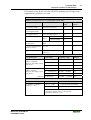
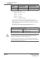
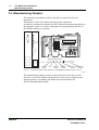
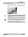
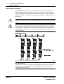
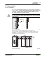
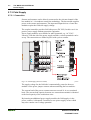
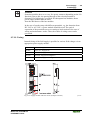
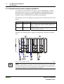
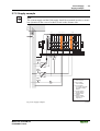
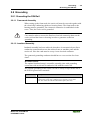
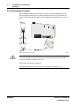
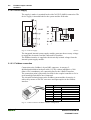
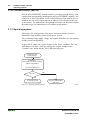
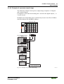
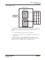
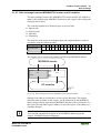
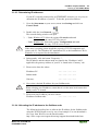
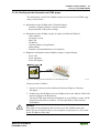
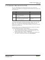
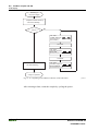
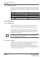
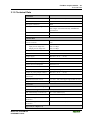
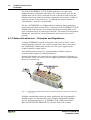
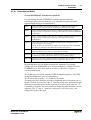
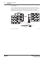
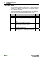
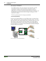
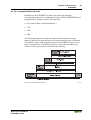
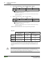
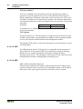
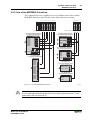
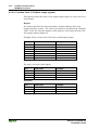
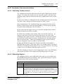
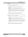
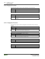
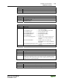
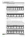
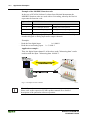
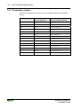
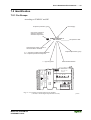
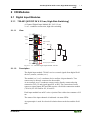
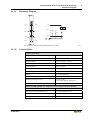
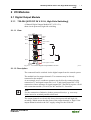
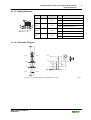
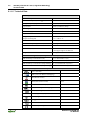
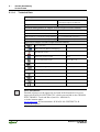
42 • Fieldbus coupler 750-342 Hardware 3.1.2.2 Device supply The supply is made via terminal bocks with CAGE CLAMP® connection. The device supply is intended both for the system and the field units. Fig. 3.1-2: Device supply G034201e The integrated internal system supply module generates the necessary voltage to supply the electronics and the connected I/O modules. The fieldbus interface is supplied with electrically isolated voltage from the internal system supply module. 3.1.2.3 Fieldbus connection Connection to the fieldbus is by an RJ45 connector. A category 5, shielded/unshielded twisted pair cable (S-UTP) with an impedance of 100 Ohm ±15% is mandatory as a connecting line for the 10BaseT Interface. The connection point is physically lowered for the coupler/controller to fit in an 80 mm high switch box once connected. The electrical isolation between the fieldbus system and the electronics is achieved by means of DC/DC converters and optocouplers in the fieldbus interface. Contact Signal 1 2 3 4 5 6 7 8 TD + TD RD + RD - Transmit + Transmit Receive + free free Receive free free Fig. 3.1-3: RJ45-connector and RJ45 connector configuration WAGO-I/O-SYSTEM 750 ETHERNET TCP/IP Fieldbus coupler 750-342 • 43 Hardware Attention! Only for use in LAN, not for connection to telecommunication circuits! 3.1.2.4 Display elements The operating condition of the fieldbus coupler or node is signaled via light diodes (LED). ETHERNET ETHERNET ON A LINK B C TxD/RxD D A LINK B TxD/RxD 24V 0V ERROR I/O ON C D 24V 0V ERROR + I/O + + + Fig. 3.1-4: Display elements 750-342 g012946x LED ON LINK TxD/RxD ERROR IO Color green green green red red /green / orange Meaning Fieldbus initialization is correct Link to a physical network exists Data exchange taking place Error on the fieldbus The 'I/O'-LED indicates the operation of the node and signals faults encountered A green Status of the operating voltage – system B or C green Status of the operating voltage – power jumper contacts (LED position is manufacturing dependent) 3.1.2.5 Configuration interface The configuration interface used for the communication with WAGO-I/OCHECK or for firmware download is located behind the cover flap. open flap Configuration interface Fig. 3.1-5: Configuration interface g012945e The communication cable (750-920) is connected to the 4 pole header. Warning The communication cable 750-920 must not be connected or disconnected while the coupler/controller is powered on! WAGO-I/O-SYSTEM 750 ETHERNET TCP/IP 44 • Fieldbus coupler 750-342 Operating system 3.1.2.6 Hardware address (MAC-ID) Each WAGO ETHERNET fieldbus coupler is provided from the factory with a unique and internationally unambiguous physical ETHERNET address, also referred to as MAC-ID (Media Access Control Identity). This address is to be found on the rear of the coupler and on an adhesive tear-off label on the side of the coupler. The address has a fixed length of 6 Bytes (48 Bit) and contains the address type, the manufacturer’s ID, and the serial number. 3.1.3 Operating system Following is the configuration of the master activation and the electrical installation of the fieldbus station to start up the system. After switching on the supply voltage, the coupler determines the I/O modules and the present configuration. In the event of a fault, the coupler changes to the "Stop" condition. The "I/O" LED flashes red. After a fault free start up, the coupler changes to the "Fieldbus start" status and the "I/O" LED lights up green. Switching on the supply voltage Initialization, Determination of the I/O modules and the configuration, “I/O” LED is blinking red Test o.k.? No Yes Fieldbus coupler is in operating mode “I/O” LED is shining green Fig. 3.1-6: Operating system 750-342 Stop red “I/O” LED indicates blink code g012920e WAGO-I/O-SYSTEM 750 ETHERNET TCP/IP Fieldbus coupler 750-342 • 45 Process image 3.1.4 Process image After switching on, the coupler recognizes all I/O modules plugged into the node which supply or wait for data (data width/bit width > 0). Analog and digital I/O modules can be mixed on the same node. Attention For the number of input and output bits or bytes of the individually activated I/O modules, please refer to the corresponding I/O module description. The coupler produces an internal process image from the data width and the type of I/O module as well as the position of the I/O modules in the node. It is divided into an input and an output data area. The data of the digital I/O modules is bit orientated, i.e. the data exchange is made bit for bit. The analog I/O modules are representative for all byte orientated I/O modules, i.e. those where the data exchange is made byte for byte. These I/O modules include for example the counter modules, I/O modules for angle and path measurement as well as the communication modules. The data of the I/O modules is separate from the local input and output process image in the sequence of their position after the coupler in the individual process image. First, all the byte oriented bus modules and then the bit oriented bus modules are stored in the process image. The bits of the digital modules are grouped to form bytes. As soon as the number of digital I/O’s exceeds 8 bits, the coupler automatically starts the next byte. Attention A process image restructuring may result if a node is changed. In this case the process data addresses also change in comparison with earlier ones. In the event of adding modules, take the process data of all previous modules into account. The coupler provides a storage area of 256 words each (word 0 - 255) for the physical input and output data. Access from the fieldbus side is fieldbus specific. For the ETHERNET TCP/IP fieldbus coupler, a MODBUS/TCP master accesses the data via implemented MODBUS functions. Here decimal and/or hexadecimal MODBUS addresses are used. More information A detailed description of these fieldbus-specific data access operations is given in the section “MODBUS functions”. More Information You can find the fieldbus specific process data architecture for all I/O Modules in the chapter „Fieldbus specific Process Data Architecture“. WAGO-I/O-SYSTEM 750 ETHERNET TCP/IP 46 • Fieldbus coupler 750-342 Data exchange 3.1.4.1 Example of a process input image The following figure is an example of a process input image. The configuration comprises of 16 digital and 8 analog inputs. The process image thus has a data length of 8 words for the analog and 1 word for the digital inputs, i.e. 9 words in total. DI DI AI AI 400 467 DI AI DI DI AI 400 467 Ethernet ON LINK TxD/RxD ERROR 750-342 W AGO ßI /O ßSY STE M I/O Eingangsklemmen 750- 400 Bit 1 Prozessabbild der Eingänge (Word) Bit 2 467 400 1 2 467 400 1 Word1 Word1 Word2 Word2 2 1 Word1 Word2 2 1 2 Word1 Word2 MODBUS-Adressen Word1 Word2 0x0000 0x0001 0x0002 0x0003 0x0004 0x0005 0x0006 0x0007 Word1 Word2 Word1 Word2 Word1 Word2 0x0008 Highbyte Lowbyte Prozessabbild der Eingänge (Bit) MODBUSAdressen 0x0000 0x0001 0x0002 0x0003 0x0004 0x0005 0x0006 0x0007 0x0008 0x0009 DI: Digitale Eingangsklemme AI: Analoge Eingangsklemme Fig. 3.1-7: Example of a process input image G012914e WAGO-I/O-SYSTEM 750 ETHERNET TCP/IP Fieldbus coupler 750-342 • 47 Data exchange 3.1.4.2 Example of a process output image The following example for the process output image comprises of 2 digital and 4 analog outputs. It comprises of 4 words for the analog and 1 word for the digital outputs, , i.e. 5 words in total. In addition, the output data can be read back by means of an offset of 200hex (0x0200) added to the MODBUS address. DO AO AO ETHERNET LINK MS NS TxD/RxD 750-341 I/O Ausgangsklemmen 750 - 501 Prozessabbild der Ausgänge (Word) 550 550 Bit 1 Word1 Word1 Bit 2 Word2 Word2 MODBUS-Adressen 0x0000 / 0x0200 0x0001 / 0x0201 0x0002 / 0x0202 0x0003 / 0x0203 0x0004 / 0x0204 Highbyte Word1 Word2 Word1 Word2 Lowbyte Prozessabbild der Eingänge (Word) MODBUS-Adressen Word1 Word2 0x0200 0x0201 0x0202 0x0203 Word1 Word2 0x0204 Highbyte Lowbyte Prozessabbild der Ausgänge (Bit) MODBUS-Adressen 0x0000 / 0x0200 0x0001 / 0x0201 Prozessabbild der Eingänge (Bit) MODBUS-Adressen 0x0200 0x0201 DO: Digitale Ausgangsklemme AO: Analoge Ausgangsklemme Fig. 3.1-8: Example of a process output image WAGO-I/O-SYSTEM 750 ETHERNET TCP/IP G015015e 48 • Fieldbus coupler 750-342 Data exchange 3.1.4.3 Process Data Architecture With some I/O modules, the structure of the process data is fieldbus specific. In the case of an Ethernet TCP/IP coupler/controller, the process image uses a word structure (with word alignment). The internal mapping method for data greater than one byte conforms to the Intel format. More Information You can find the fieldbus specific process data architecture for all I/O Modules of the WAGO-I/O-SYSTEM 750 and 753 in the chapter „ Process Data Architecture for ETHERNET“. 3.1.5 Data Exchange Process data exchange with the ETHERNET TCP/IP fieldbus coupler occurs via the MODBUS/TCP protocol. MODBUS/TCP works according to the master/slave principle. The master is a superimposed control unit, i.e. a PC or a PLC device. The ETHERNET TCP/IP couplers of the WAGO-I/O-SYSTEM are slave devices. The master makes a query for communication. Through adressing, this query can be sent to a specific node. The nodes receive the query and return a response to the master, depending on the kind of query. A coupler can communicate with a certain number of simultaneous connections (socket connections) to other network subscribers: • • 1 connection for HTTP (reading HTML pages from coupler) and 5 connections via MODBUS/TCP (reading or writing input and output data from coupler). The maximum number of simultaneous connections cannot be exceeded. If further connections are to be made, terminate existing connections beforehand. For a data exchange, the ETHERNET TCP/IP fieldbus coupler is equipped with two interfaces: • the interface to fieldbus (-master) and • the interface to the bus modules. Data exchange takes place between MODBUS master and the bus modules. The master accesses the bus module data via implemented MODBUS functions. WAGO-I/O-SYSTEM 750 ETHERNET TCP/IP Fieldbus coupler 750-342 • 49 Data exchange 3.1.5.1 Memory areas fieldbus coupler memory area for input data word 0 I/O modules 1 input modules fieldbus master word 255 memory area for output data word 0 2 output modules I O word 255 Fig. 3.1-9: Memory areas and data exchange for a fieldbus coupler g012939e The coupler process image contains the physical data of the bus modules in a storage area for input data and in a storage area for output data (word 0 ... 255 each). (1) The input module data can be read from the fieldbus side. (2) In the same manner, writing on the output modules is possible from the fieldbus side. In addition, all output data of the ETHERNET TCP/IP coupler are mirror imaged on a storage area with the address offset 0x0200. This allows to read output values back by adding 0x0200 to the MODBUS address. WAGO-I/O-SYSTEM 750 ETHERNET TCP/IP 50 • Fieldbus coupler 750-342 Data exchange 3.1.5.2 Addressing 3.1.5.2.1 Addressing the I/O modules The arrangement of the I/O modules in a node is optional. When addressing, first of all the more complex modules (modules occupying 1 or more bytes) are taken into account in accordance with their physical order behind the fieldbus coupler. As such, they occupy the addresses starting with word 0. Following this, the data of the other modules (modules occupying less than 1 byte) follow, grouped into bytes. In accordance with the physical byte-wise order this data is used to fill up the bytes. As soon as a full byte is occupied by the bit-oriented modules, the next byte is automatically started. Attention For the number of input and output bits and/or bytes of the individual activated bus modules, please refer to the pertaining descriptions of the bus modules. Attention Once a node is modified, a new architecture of the process image can result. As such, the address of the process data will alsochange. In the event of adding modules, the process data of all previous modules has to be taken into account. Data width ≥ 1 Word / channel Data width = 1 Bit / channel Analog input modules Digital input modules Analog output modules Digital output modules Input modules for thermal elements Digital output modules with diagnosis (2 Bit / channel) Input modules for resistance sensors Power supply modules with fuse holder / diagnosis Pulse width output modules Solid State power relay Interface module Relay output modules Up/down counter I/O modules for angle and path measurement Table 3.1.1: I/O module data width WAGO-I/O-SYSTEM 750 ETHERNET TCP/IP Fieldbus coupler 750-342 • 51 Data exchange 3.1.5.3 Data exchange between MODBUS/TCP master and I/O modules The data exchange between the MODBUS/TCP master and the I/O modules is made by the implemented MODBUS functions in the coupler with reading and writing in bits or bytes. The controller handles four different types of process data: • Input words • Output words • Input bits • Output bits The word for word access to the digital input and output modules is made in accordance with the following table: Digital Inputs/Outputs 16. Process data word Bit Bit Bit 15 14 13 High-Byte D1 Byte 15. 14. 13. 12. 11. 10. 9. Bit 12 Bit 11 Bit 10 Bit 9 Bit 8 8. 7. 6. Bit Bit Bit 7 6 5 Low-Byte D0 5. 4. 3. 2. 1. Bit 4 Bit 3 Bit 2 Bit 1 Bit 0 Table 3.1.2: Allocation of digital inputs/outputs to process data word acc. Intel format The outputs can be read back by adding 0x0200 to the MODBUS address. MODBUS master 0x000 0x000 (0x200) PIO PII 0x0FF 0x0FF (0x2FF) Outputs Inputs I/O modules PII = Process Input Image PIO = Process Output Image Fieldbus Coupler Fig. 3.1-10: Data exchange between the MODBUS master and I/O modules g012927e Starting from address 0x1000 there are the register functions. The register functions made available in the coupler, can be addressed by the MODBUS master along with the implemented MODBUS function codes (read/write). To this effect, the individual register address is entered in place of the address of a module channel. More information You can find a detailed description of the MODBUS addressing in the chapter „MODBUS Register Mapping“. WAGO-I/O-SYSTEM 750 ETHERNET TCP/IP 52 • Fieldbus coupler 750-342 Starting up a Fieldbus Node 3.1.6 Starting up a Fieldbus Node This chapter shows the step-by-step procedure for starting up a WAGO ETHERNET TCP/IP fieldbus node. The following also contains a description of how to read out the coupler-internal HTML pages. Attention This description is given as an example and is limited to the execution of a local startup of an individual ETHERNET fieldbus node with a computer running under windows which is not connected to a network. Direct Internet connection should only be performed by an authorized network administrator and is, therefore, not described in this manual. The procedure contains the following steps: 1. 2. 3. 4. 5. 6. Noting the MAC-ID and establishing the fieldbus node Connecting the PC and fieldbus node Determining the IP address Allocation of the IP address to the fieldbus node Function of the fieldbus tests Reading out information as HTML pages 3.1.6.1 Note the MAC-ID and establish the fieldbus node Before establishing your fieldbus node, please note the hardware address (MAC-ID) of your ETHERNET fieldbus coupler. This is located on the rear of the fieldbus coupler and on the self-adhesive tear-off label on the side of the fieldbus coupler. MAC-ID of the fieldbus coupler will be in this format: ----- ----- ----- ----- ----- -----. 3.1.6.2 Connecting PC and fieldbus node Connect the assembled ETHERNET TCP/IP fieldbus node via a hub or directly to the PC using a 10Base-T cable. Attention For a direct connection, a crossover cable is required instead of a parallel cable. Now start the PC, functioning as master and BootP server, and switch on the voltage supply on the fieldbus coupler (DC 24 V power pack). Once the operating voltage has been switched on, the initialization starts. The fieldbus coupler determines the configuration of the bus modules and creates the process image. During the startup the 'I/O' LED (Red) flashes at high frequency. When the 'I/O' LED and the 'ON' LED light up green, the fieldbus coupler is ready for operation. If an error has occurred during startup, it is indicated as an error code by the 'I/O'-LED flashing (red). WAGO-I/O-SYSTEM 750 ETHERNET TCP/IP Fieldbus coupler 750-342 • 53 Starting up a Fieldbus Node 3.1.6.3 Determining IP addresses If your PC is already connected to an ETHERNET network, it is very easy to determine the IP address of your PC. To do this, proceed as follows: 1. Go to the Start menu on your screen, menu item Settings and click on Control Panel. 2. Double click the icon Network. The network dialog window will open. 3. - Under Windows NT: Select the register: Protocols and mark the entry TCP/IP protocol. - Under Windows 9x: Select the register: Configuration and mark the entry TCP/IP network card. Attention If the entry is missing, please install the respective TCP/IP component and restart your PC. The Windows-NT installation CD, or the installations CD for Windows 9x is required for the installation. 4. Subsequently, click the button "Properties...". The IP address and the subnet mask are found in the ‘IP address’ tab.If applicable, the gateway address of your PC is found in the ‘Gateway’ tab. 5. Please write down the values: IP address PC: ----- . ----- . ----- . ----- Subnet mask: ----- . ----- . ----- . ----- Gateway: ----- . ----- . ----- . ----- 6. Now select a desired IP address for your fieldbus node. Attention When selecting your IP address, ensure that it is in the same local network in which your PC is located. 7. Please note the IP address you have chosen: IP address fieldbus node: ----- . ----- . ----- . ----- 3.1.6.4 Allocating the IP address to the fieldbus node The following describes how to allocate the IP address for the fieldbus node using the WAGO BootP server by way of an example. You can download a free copy from WAGO over the Internet under: http://www.wago.com/wagoweb/usa/eng/support/downloads/index.htm. WAGO-I/O-SYSTEM 750 ETHERNET TCP/IP 54 • Fieldbus coupler 750-342 Starting up a Fieldbus Node Note The IP address can be allocated under other operating systems (i.e. under Linux) as well as with any other BootP servers. Attention The IP address can be allocated in a direct connection via a crossover cable or via a parallel cable and a hub. An allocation over a switch is not possible. BootP table Attention Prerequisite for the following steps is the correct installation of the WAGO BootP server. 1. Go to the Start menu, menu item Programs / WAGO Software / WAGO BootP Server and click on WAGO BootP Server configuration. An editable table will appear: "bootptab.txt". This table displays the data basis for the BootP server. Directly following the list of all notations used in the BootP table there are two examples for the allocation of an IP address. "Example of entry with no gateway" and "Example of entry with gateway". Fig. 3.1-11: BootP table p012908e The examples mentioned above contain the following information: Declaration node1, node2 ht=1 Meaning Any name can be given for the node here. Specify the hardware type of the network here. The hardware type for ETHERNET is 1. (The numbers are described in RFC1700) ha=0030DE000100 Specify the hardware address or the MAC-ID of the ETHERNET ha=0030DE000200 fieldbus coupler (hexadecimal). ip= 10.1.254.100 Enter the IP address of the ETHERNET fieldbus coupler (decimal) ip= 10.1.254.200 here. T3=0A.01.FE.01 Specify the gateway IP address here. Write the address in hexadecimal form. sm=255.255.0.0 In addition enter the Subnet-mask of the subnet (decimal), where the ETHERNET fieldbus coupler belongs to. WAGO-I/O-SYSTEM 750 ETHERNET TCP/IP Fieldbus coupler 750-342 • 55 Starting up a Fieldbus Node No gateway is required for the local network described in this example. Therefore, the first example: "Example of entry with no gateway" can be used. 2. Move the mouse pointer to the text line: "node1:ht=1:ha=0030DE000100:ip=10.1.254.100" and mark the 12 character hardware address which is entered after ha=... Enter the MAC-ID of your own network coupler. 3. If you want to give your fieldbus node a name, delete the name "node1" and enter any name in its place. 4. To assign the coupler a desired IP address, mark the IP address specified in the example which is entered after ip=... Replace it with the IP address you have selected. 5. Because the second example is not necessary at present, insert a “#” in front of the text line of the second example: "# node2:hat=1:ha=003 0DE 0002 00:ip=10.1.254.200:T3=0A.01.FE.01", so that this line will be ignored. Note To address more fieldbus nodes, enter a corresponding text line showing the corresponding entries for each node. 6. Save the altered settings in this text file "bootptab.txt". To do this go to the File menu, menu item Save, and close the editor. BootP Server 7. Now open the dialog window for the WAGO BootP server by going to the Start menu on your screen surface, menu item Program / WAGO Software / WAGO BootP Server and click on WAGO BootP Server. 8. Click on the "Start" button in the opened dialog window. This will activate the inquiry/response mechanism of the BootP protocol. A series of messages will be displayed in the BootP server. The error messages indicate that some services (i.e. port 67, port 68) in the operating system have not been defined. Fig. 3.1-12: Dialog window of the WAGO BootP server with messages WAGO-I/O-SYSTEM 750 ETHERNET TCP/IP g012909d 56 • Fieldbus coupler 750-342 Starting up a Fieldbus Node 9. Now it is important to restart the coupler by resetting the hardware . This ensures that the new IP address will be accepted by the coupler. To do this, cycle power to the fieldbus coupler for approx. 2 seconds. Following this, the IP address in the coupler is permanently stored and maintained even once the coupler is removed or following a longer voltage failure. 10. Subsequently, click on the "Stop" button and then on the "Exit" button, to close the BootP Server again. 3.1.6.5 Testing the function of the fieldbus node 1. To test the communication with the coupler and the correct assignment of the IP address call up the DOS prompt under Start menu / Program / MSDOS Prompt. 2. Enter the command: "ping" with the IP address you have assigned in the following form: ping [space] XXXX . XXXX . XXXX . XXXX (=IP address). Example: ping 10.1.254.202 Fig. 3-13: Example for the function test of a fieldbus node P012910d 3. When the Return key has been pressed, your PC will receive a response from the coupler, which will then be displayed in the DOS prompt. If the error message: "Timeout" appears instead, please compare your entries again to the allocated IP address. 4. When the test has been performed successfully, you can close the DOS prompt. The network node has now been prepared for communication. WAGO-I/O-SYSTEM 750 ETHERNET TCP/IP Fieldbus coupler 750-342 • 57 Starting up a Fieldbus Node 3.1.6.6 Reading out the information as HTML pages The information saved in the fieldbus coupler can be read as an HTML page using a web browser. • Information on the fieldbus node (Terminal Status): - Number of digital, analog or complex modules Representation of the process image • Information on the fieldbus coupler (Coupler and Network Details): - Order number Firmware version MAC-ID IP address Gateway address (if applicable) Subnet mask Number of transmitted and received packets • Diagnostic information on the fieldbus coupler (Coupler Status): - Error code Error argument Error description Fig. 3-14: Reading out the information via the HTTP protocol G012916d Please proceed as follows: 1. Open a web browser such as Microsoft Internet-Explorer, Netscape Navigator, ... 2. Simply enter the IP address of your fieldbus node in the address field of the browser and press the Return key. The first HTML page with the information on your fieldbus coupler will be displayed in the browser window. Use the hyperlinks to find out more information. Attention If the pages are not displayed after local access to the fieldbus node, then define in your web browser that, as an exception, no proxyserver is to be used for the IP address of the node. WAGO-I/O-SYSTEM 750 ETHERNET TCP/IP 58 • Fieldbus coupler 750-342 LED Display 3.1.7 LED Display The coupler possesses several LED’s for displaying the coupler operating status and the complete node status. ETHERNET ETHERNET ON A LINK B TxD/RxD C D 24V 0V ERROR I/O ON A LINK B TxD/RxD C D 24V 0V ERROR + + I/O + + Fig. 3-15: Display elements 750-342 G012946x The LEDs can be divided into three groups. The first group of LEDs display the status of the Ethernet fieldbus. It contains the solid color LEDs, labelled as: ‘ON‘ (green), ‘LINK‘ (green), ‘TxD/RxD‘ (green) and ‘ERROR‘ (red). The second group of LEDs is a three-color LED (red/green/orange). This LED is labelled ‘I/O’, and displays the status of the internal bus and i. e. the status of the fieldbus node. The third group uses solid colored green LEDs. They are located on the righthand side of the coupler power supply. These display the status of the supply. 3.1.7.1 Fieldbus status The operating status of the communication via ETHERNET is signalled by means of the top LED group (ON, LINK, TxD/RxD and ERROR). LED Meaning Trouble shooting ON green Fieldbus initialization is correct OFF Fieldbus initialization is not correct, no function or self-test Check the supply voltage (24V and 0V), check the IP configuration LINK green Link to a physical network exists OFF No link to a physical network Check the fieldbus connection. TxD/RxD green Data exchange taking place OFF No data exchange ERROR red Error on the fieldbus OFF No error on the fieldbus, normal operation WAGO-I/O-SYSTEM 750 ETHERNET TCP/IP Fieldbus coupler 750-342 • 59 LED Display 3.1.7.2 Node status – Blink code from the 'I/O' LED The ‘I/O‘-LED displays the communication status of the internal bus. Additionally, this LED is used to display fault codes (blink codes) in the event of a system error. LED Meaning Trouble shooting I/O Green Fieldbus coupler operating perfectly Red a) During startup of fieldbus coupler: Internal bus being initialized, Startup displayed by LED flashing fast for approx. 1-2 seconds Red b) After startup of fieldbus coupler: Errors, which occur, are indicated by three consecutive flashing sequences. There is a short pause between each sequential flash. Evaluate the fault message (fault code and fault argument). The coupler starts up after switching on the supply voltage. The "I/O" LED blinks. The "I/O" LED has a steady light following a fault free run-up. In the case of a fault the "I/O" LED continues blinking. The fault is cyclically displayed by the blink code. Detailed fault messages are displayed with the aid of a blink code. A fault is cyclically displayed with up to 3 blink sequences. • The first blink sequence (approx. 10 Hz) starts the fault display. • The second blink sequence (approx. 1 Hz) following a pause. The number of blink pulses indicates the fault code. • The third blink sequence (approx. 1 Hz) follows after a further pause. The number of blink pulses indicates the fault argument. WAGO-I/O-SYSTEM 750 ETHERNET TCP/IP 60 • Fieldbus coupler 750-342 LED Display Switching on the power supply Coupler/Controller starts up “I/O”-LED is blinking Test o.k.? No Yes “I/O” LED 1st flash sequence (Introduction of the error indication) 1st break “I/O” LED 2nd flash sequence Error code (Number of flash cycles) 2nd break “I/O”-LED is shining “I/O” LED 3rd flash sequence Error argument (Number of flash cycles) ready for operation Fig. 3.1-16: Signalling of the LED for indication of the node status g012911e After clearing a fault, restart the coupler by cycling the power. WAGO-I/O-SYSTEM 750 ETHERNET TCP/IP Fieldbus coupler 750-342 • 61 LED Display Fault message of the ‘I/O‘-LED 1 st flash sequence: Start of the Fault message 2 nd flash sequence: Fault code 3 rd flash sequence: Fault argument Fault code 1: "Hardware and Configuration fault" Fault argument WAGO-I/O-SYSTEM 750 ETHERNET TCP/IP Fault description Trouble shooting - Invalid checksum within the parameter range of fieldbus coupler Turn off the power supply of the node, exchange the bus coupler and turn the power supply on again. 1 Overflow of the internal buffer memory for the inline code Turn off the power supply of the node, reduce number of I/O modules and turn the power supply on again. If the error still exists, exchange the bus coupler. 2 I/O module(s) with unsupported data type 3 Unknown program module type of the flash program memory 4 Fault when writing data within the flash memory 5 Fault when deleting a flash sector 6 Changed I/O module configuration determined after AUTORESET Detect faulty I/O module as follows: turn off the power supply. Place the end module in the middle of the fieldbus node. Turn the power supply on again. – If the LED is still blinking, turn off the power supply and place the end module in the middle of the first half of the node (towards the coupler). – If the LED doesn’t blink, turn off the power supply and place the end module in the middle of the second half of the node (away from the coupler). Turn the power supply on again. Repeat this procedure until the faulty I/O module is detected. Replace the faulty I/O module. Ask about a firmware update for the fieldbus coupler. Turn off the power supply of the node, exchange the bus coupler and turn the power supply on again. Turn off the power supply of the node, exchange the bus coupler and turn the power supply on again. Turn off the power supply of the node, exchange the bus coupler and turn the power supply on again. Restart the fieldbus coupler by turning the power supply off and on again. 62 • Fieldbus coupler 750-342 LED Display 7 8 9 10 11 12 13 14 Fault when writing data in the serial EEPROM Turn off the power supply of the node, exchange the bus coupler and turn the power supply on again. Invalid Hardware Firmware Turn off the power supply of the combination node, exchange the bus coupler and turn the power supply on again. Invalid checksum within the Turn off the power supply of the serial EEPROM node, exchange the bus coupler and turn the power supply on again. serial EEPROM initialization Turn off the power supply of the fault node, exchange the bus coupler and turn the power supply on again. Fault when reading out data from Turn off the power supply of the the EEPROM node, exchange the bus coupler and turn the power supply on again. Timeout when writing data in the Turn off the power supply of the EEPROM node, exchange the bus coupler and turn the power supply on again. - not used Maximum number of Gateway or Turn off the power supply of the Mailbox I/O modules exceeded node, reduce number of Gateway or Mailbox I/O modules and turn the power supply on again. Fault code 2 -not usedFault argument - Fault description Trouble shooting not used - WAGO-I/O-SYSTEM 750 ETHERNET TCP/IP Fieldbus coupler 750-342 • 63 LED Display Fault code 3: "Internal bus protocol fault" Fault argument - WAGO-I/O-SYSTEM 750 ETHERNET TCP/IP Fault description Trouble shooting Internal bus communication malfunction; faulty device can’t be detected If the fieldbus node comprises internal system supply modules (750-613), make sure first that the power supply of these modules is functioning. This is indicated by the status LEDs. If all I/O modules are connected correctly or if the fieldbus node doesn’t comprise 750-613 modules you can detect the faulty I/O module as follows: turn off the power supply of the node. Place the end module in the middle of the fieldbus node. Turn the power supply on again. – If the LED is still blinking, turn off the power supply and place the end module in the middle of the first half of the node (towards the coupler). – If the LED doesn’t blink, turn off the power supply and place the end module in the middle of the second half of the node (away from the coupler). Turn the power supply on again. Repeat this procedure until the faulty I/O module is detected. Replace the faulty I/O module. If there is only one I/O module left but the LED is still blinking, then this I/O module or the coupler is defective. Replace defective component. 64 • Fieldbus coupler 750-342 LED Display Fault code 4: "Internal bus physical fault" Fault argument Fault description Trouble shooting - Error in internal bus data Turn off the power supply of the communication or interruption of node. Place an I/O module with the internal bus at the coupler process data behind the coupler and note the error argument after the power supply is turned on. If no error argument is given by the I/O LED, replace the coupler. Otherwise detect faulty I/O module as follows: turn off the power supply. Place the end module in the middle of the fieldbus node. Turn the power supply on again. – If the LED is still blinking, turn off the power supply and place the end module in the middle of the first half of the node (towards the coupler). – If the LED doesn’t blink, turn off the power supply and place the end module in the middle of the second half of the node (away from the coupler). Turn the power supply on again. Repeat this procedure until the faulty I/O module is detected. Replace the faulty I/O module. If there is only one I/O module left but the LED is still blinking, then this I/O module or the coupler is defective. Replace defective component. n* Turn off the power supply of the Interruption of the internal bus after the nth process data module. node, exchange the (n+1)th process data module and turn the power supply on again. Fault code 5: "Internal bus initialization fault" Fault argument n* Fault description Trouble shooting Error in register communication during internal bus initialization Turn off the power supply of the node and replace nth process data module and turn the power supply on again. WAGO-I/O-SYSTEM 750 ETHERNET TCP/IP Fieldbus coupler 750-342 • 65 LED Display Fault code 6: "Fieldbus specific faults" Fault argument Fault description Trouble shooting 1 No BootP server reply Check the settings of BootP server. 2 Not identified ETHERNET coupler Turn off the power supply of the node, exchange fieldbus coupler and turn the power supply on again. 3 Invalid MACID Turn off the power supply of the node, exchange fieldbus coupler and turn the power supply on again. 4 TCP/IP initialization error Restart the fieldbus coupler by turning the power supply off and on again. If the error still exists, exchange the bus coupler. Fault code 7 -not usedFault argument - Fault description Trouble shooting not used - Fault code 8 -not usedFault argument - Fault description Trouble shooting not used - Fault code 9 "CPU Trap Error" Fault argument Fault description Trouble shooting 1 Illegal Opcode 2 Stack overflow Error in the program sequence. Contact the WAGO I/O-Support 3 Stack underflow 4 NMI * The number of blink pulses (n) indicates the position of the I/O module. I/O modules without data are not counted (e.g. supply module without diagnosis) Example for a fault message; Fault: The 13th I/O module has been removed 1. The "I/O" LED starts the fault display with the first blink sequence (approx. 10 flashes/second). 2. The second blink sequence (1 flash/second) follows the first pause. The "I/O" LED blinks four times and thus signals the fault code 4 (internal bus data fault). 3. The third blink sequence follows the second pause. The "I/O " LED blinks twelve times. The fault argument 12 means that the internal bus is interrupted after the 12th I/O module. WAGO-I/O-SYSTEM 750 ETHERNET TCP/IP 66 • Fieldbus coupler 750-342 Fault behavior 3.1.7.3 Supply voltage status There are two green LED’s in the coupler supply section to display the supply voltage. The left LED (A) indicates the 24 V supply for the coupler. The right hand LED (B or C) signals the supply to the field side, i.e. the power jumper contacts. LED Meaning Trouble shooting Operating voltage for the system exists. No operating voltage for the system. Check the supply voltage (24V and 0V). A green OFF B or C green OFF Operating voltage for the power jumper contacts exists. No operating voltage for the the power jumper Check the supply voltage (24V and 0V). contacts. 3.1.8 Fault behavior 3.1.8.1 Fieldbus failure A field bus failure is given i. e. when the master cuts-out or the bus cable is interrupted. A fault in the master can also lead to a fieldbus failure. A field bus failure is indicated when the red "ERROR"-LED is illuminated. If the watchdog is activated, the fieldbus coupler firmware evaluates the watchdog-register in the case of fault free communication, and the coupler answers all following MODBUS TCP/IP requests with the exception code 0x0004 (Slave Device Failure). More information For detailed information on the Watchdog register see Chaper "MODBUS Functions"; "Watchdog (Fieldbus failure)". 3.1.8.2 Internal bus fault An internal bus fault is created, for example, if an I/O module is removed. If this fault occurs during operation the output modules behave in the same manner as an I/O module stop. The "I/O" LED blinks red. The coupler generates a fault message (fault code and fault argument). After clearing the internal bus fault, restart the coupler by cycling the power. The coupler starts up. The transfer of the process data is then resumed and the node outputs are correspondingly set. WAGO-I/O-SYSTEM 750 ETHERNET TCP/IP Fieldbus coupler 750-342 • 67 Technical Data 3.1.9 Technical Data System data Number of nodes limited by ETHERNET specification Transmission medium Twisted Pair S-UTP 100 Ω cat. 5 Buscoupler connection RJ45 Max. length of fieldbus segment 100 m between hub station and 750-342; max. length of network limited by ETHERNET specification Baud rate 10 Mbit/s Protocols MODBUS/TCP, MODBUS/UDP, HTTP, BootP Technical Data No. of I/O modules with bus extension 64 250 Fieldbus Input process image max. Output process image max. max. 512 Byte max. 512 Byte Configuration via PC Max. no. of socket connections 1 HTTP, 5 MODBUS/TCP Voltage supply DC 24 V (-25 % ... + 30 %) Input currentmax 500 mA at 24 V Efficiency of the power supply 87 % Internal current consumption 200 mA at 5 V Total current for I/O modules 1800 mA at 5 V Isolation 500 V system/supply Voltage via power jumper contacts DC 24 V (-25 % ... + 30 %) Current via power jumper contactsmax DC 10 A Dimensions (mm) W x H x L 51 x 65* x 100 (*from upper edge of DIN 35 rail) Weight ca. 195 g Accessories Miniature WSB quick marking system Standards and Regulations (cf. Chapter 2.2) EMC CE-Immunity to interference acc. to EN 50082-2 (96) EMC CE-Emission of interference acc. to EN 50081-1 (93) EMC marine applications-Immunity to acc. to Germanischer Lloyd (1997) interference EMC marine applications-Emission of acc. to Germanischer Lloyd (1997) interference Approvals (cf. Chapter 2.2) WAGO-I/O-SYSTEM 750 ETHERNET TCP/IP 68 • Fieldbus coupler 750-342 Technical Data CULUS (UL508) ABS (American Bureau of Shipping) 1) BV (Bureau Veritas) 1) DNV (Det Norske Veritas) 1) Cl. B GL (Germanischer Lloyd) 1) Cat. A, B, C, D KR (Korean Register of Shipping) 1) LR (Lloyd's Register) 1) NKK Env. 1, 2, 3, 4 NKK (Nippon Kaiji Kyokai) 1) RINA (Registro Italiano Navale) 1) CULUS (UL1604) DEMKO Class I Div2 ABCD T4A II 3 G EEx nA II T4 Conformity Marking 1) Consider chapter: „Supplementary power supply regulations”! WAGO-I/O-SYSTEM 750 ETHERNET TCP/IP Fieldbus Communication ETHERNET • 69 4 Fieldbus Communication 4.1 ETHERNET 4.1.1 General ETHERNET is a technology, which has been proven and established as an effective means of data transmission in the field of information technology and office communication. Within a short time ETHERNET has also made a successful breakthrough in the area of private PC networks throughout the world. This technology was developed in 1972 by Dr. Robert M. Metcalfe, David R. Boggs, Charles Thacker, Butler W. Lampson, and Xerox (Stanford, Ct.). Standardization (IEEE 802.3) took place in 1983. ETHERNET predominantly uses coaxial cables or twisted pair cables as a transmission medium. Connection to ETHERNET, often already existing in networks, (LAN, Internet) is easy and the data exchange at a transmission rate of 10 Mbps or for some couplers/controllers also 100 Mbps is very fast. ETHERNET has been equipped with higher level communication software in addition to standard IEEE 802.3, such as TCP/IP (Transmission Control Protocol / Internet Protocol) to allow communication between different systems. The TCP/IP protocol stack offers a high degree of reliability for the transmission of information. In the ETHERNET based (programmable) fieldbus couplers and controllers developed by WAGO, usually various application protocols have been implemented on the basis of the TCP/IP stack. These protocols allow the user to create applications (master applications) with standardized interfaces and transmit process data via an ETHERNET interface. In addition to a series of management and diagnostic protocols, fieldbus specific application protocols are implemented for control of the module data, depending upon the coupler or controller, e. g. MODBUS TCP (UDP), EtherNet/IP, BACnet, KNXNET/IP, PROFINET, Powerlink, Sercos III or others. Information such as the fieldbus node architecture, network statistics and diagnostic information is stored in the ETHERNET (programmable) fieldbus couplers and controllers and can be viewed as HTML pages via a web browser (e.g., Microsoft Internet-Explorer, Netscape Navigator) being served from the HTTP server in the couplers and controllers. Furthermore, depending on the requirements of the respective industrial application, various settings such as selection of protocols, TCP/IP, internal clock and security configurations can be performed via the web-based management system. However, you can also load web pages you have created yourself into the couplers/controllers, which have an internal file system, using FTP. WAGO-I/O-SYSTEM 750 ETHERNET TCP/IP 70 • Fieldbus Communication ETHERNET The WAGO ETHERNET TCP/IP fieldbus node does not require any additional master components other than a PC with a network card. So, the fieldbus node can be easily connected to local or global networks using the fieldbus connection. Other networking components such as hubs, switches or repeaters can also be used. However, to establish the greatest amount of “determinism” a switch is recommended. The use of ETHERNET as a fieldbus allows continuous data transmission between the plant floor and the office. Connection of the ETHERNET TCP/IP fieldbus node to the Internet even enables industrial processing data for all types of applications to be called up world-wide. This makes site independent monitoring, visualization, remote maintenance and control of processes possible. 4.1.2 Network Architecture – Principles and Regulations A simple ETHERNET network is designed on the basis of one PC with a network interface card (NI), one crossover connection cable (if necessary), one ETHERNET fieldbus node and one 24 V DC power supply for the coupler/controller voltage source. Each fieldbus node consists of a (programmable) fieldbus coupler or controller and a number of needed I/O modules. Sensors and actuators are connected to the digital or analog I/O modules on the field side. These are used for process signal acquisition or signal output to the process, respectively. Fig. 4-1. Connection Example and Principle of a Fieldbus Node for a Network Architecture 1Netwerkknotene Fieldbus communication between master application and (programmable) fieldbus coupler or controller takes place using the implemented fieldbus specific application protocol, e. g. MODBUS TCP (UDP), EtherNet/IP, BACnet, KNXNET/IP, PROFINET, Powerlink, Sercos III or others. WAGO-I/O-SYSTEM 750 ETHERNET TCP/IP Fieldbus Communication ETHERNET • 71 4.1.2.1 Transmission Media General ETHERNET transmission standards For transmitting data the ETHERNET standard supports numerous technologies with various parameters (e.g., transmission speed, medium, segment length and type of transmission). 1Base5 Uses a 24 AWG UTP (twisted pair cable) for a 1Mbps baseband signal for distances up to 500 m (250 m per segment) in a physical star topology. 10Base2 Uses a 5 mm 50 Ohm coaxial cable for a 10Mbps baseband signal for distances of up to 185 m in a physical bus topology (often referred to as Thin ETHERNET or ThinNet). 10Base5 Uses a 10 mm 50 Ohm coaxial cable for a 10Mbps baseband signal for distances of up to 500 m in a physical bus topology (often referred to as Thick ETHERNET). 10Base-F Uses a fiber-optic cable for a 10Mbps baseband signal for distances of up to 4 km in a physical star topology. (There are three sub-specifications: 10Base-FL for fiber-optic link, 10Base-FB for fiber-optic backbone and 10Base-FP for fiber-optic passive). 10Base-T Uses a 24 AWG UTP or STP/UTP (twisted pair cable) for a 10Mbps baseband signal for distances up to 100 m in a physical star topology. 10Broad36 Uses a 75 Ohm coaxial cable for a 10Mbps baseband signal for distances of up to 1800 m (or 3600 m with double cables) in a physical bus topology. 100BaseTX Specifies a 100 Mbps transmission with a twisted pair cable of Category 5 and RJ45-connectors. A maximum segment of 100 meters may be used. Tab. 4-1: ETHERNET Transmission Standards Beyond that there are still further transmission standards, for example: 100Base-T4 (Fast ETHERNET over twisted conductors), 100Base-FX (Fast ETHERNET over fiber-optic cables) or P802.11 (Wireless LAN) for a wireless transmission. The media types are shown with their IEEE shorthand identifiers. The IEEE identifiers include three pieces of information. The first item, for example, “10”, stands for the media. The third part of the identifier provides a rough indication of segment type or length. For thick coaxial cable, the “5” indicates a 500 meter maximum length allowed for individual thick coaxial segments. For thin coaxial cable, the “2” is rounded up from the 185 meter maximum length for individual thin coaxial segments. The “T” and “F” stand for ‘twisted pair’ and ‘fiber optic’, and simply indicate the cable type. WAGO-I/O-SYSTEM 750 ETHERNET TCP/IP 72 • Fieldbus Communication ETHERNET 10Base-T, 100BaseTX Either the 10BaseT standard or 100BaseTX can be used for the WAGO ETHERNET fieldbus node. The network architecture is very easy and inexpensive to assemble with SUTP cable as transmission medium or with cables of STP type. Both types of cable can be obtained from any computer dealer. S-UTP cable (screened unshielded twisted pair) is single-shielded cable of Category 5 with overall shield surrounding all twisted unshielded conductor pairs and an impedance of 100 ohm. STP cable (shielded twisted pair) is cable of Category 5 with stranded and individually shielded conductor pairs; no overall shield is provided. Wiring of the fieldbus nodes Maybe, a crossover cable is required for direct connection of a fieldbus node to the network card of the PC. Fig. 4-2: Direct Connection of a Node with Crossover Cable g012906d If several fieldbus nodes are to be connected to a network card, the fieldbus nodes can be connected via an ETHERNET switch or hub with straight through/parallel cables. Fig. 4-3: Connection of a Node by means of a Hub with Parallel cables g012908d WAGO-I/O-SYSTEM 750 ETHERNET TCP/IP Fieldbus Communication ETHERNET • 73 An ETHERNET switch is a device that allows all connected devices to transmit and receive data with each other. The switch can also be viewed as a “data traffic cop” where the hub “polices” the data coming in and going out of the individual ports, so the data will only be transmitted to the required node. WAGO recommends using a switch rather then a hub, this will allow for a more deterministic architecture. Attention The cable length between the node and the hub cannot be longer than 100 m (328 ft.) without adding signal conditioning systems (i.e., repeaters). Various possibilities are described in the ETHERNET standard for networks covering larger distances. 4.1.2.2 Network Topologies In the case of 10Base-T, or 100BaseTX several stations (nodes) are connected using a star topology according to the 10Base-T ETHERNET Standard. Therefore, this manual only deals with the star topology, and the tree topology for larger networks in more detail. Star Topology A star topology consists of a network in which all nodes are connected to a central point via individual cables. Fig. 4-4: Star Topology G012903e A star topology offers the advantage of allowing the extension of an existing network. Stations can be added or removed without network interruption. Moreover, in the event of a defective cable, only the network segment and the node connected to this segment is impaired. This considerably increases the fail-safe of the entire network. WAGO-I/O-SYSTEM 750 ETHERNET TCP/IP 74 • Fieldbus Communication ETHERNET Tree Topology The tree topology combines characteristics of linear bus and star topologies. It consists of groups of star-configured workstations connected to a linear bus backbone cable. Tree topologies allow for the expansion of an existing network, and enables schools, etc. to configure a network to meet their needs. Fig. 4-5: Tree Topology G012904e WAGO-I/O-SYSTEM 750 ETHERNET TCP/IP Fieldbus Communication ETHERNET • 75 5-4-3 Rule A consideration in setting up a tree topology using ETHERNET protocol is the 5-4-3 rule. One aspect of the ETHERNET protocol requires that a signal sent out on the network cable must reach every part of the network within a specified length of time. Each concentrator or repeater that a signal goes through adds a small amount of time. This leads to the rule that between any two nodes on the network there can only be a maximum of 5 segments connected through 4 repeators/concentrators. In addition, only 3 of the segments may be populated (trunk) segments if they are made of coaxial cable. A populated segment is one that has one or more nodes attached to it. In Figure 5-5, the 5-4-3 rule is adhered to. The furthest two nodes on the network have 4 segments and 3 repeators/concentrators between them. This rule does not apply to other network protocols or ETHERNET networks where all fiber optic cabling or a combination of a backbone with UTP cabling is used. If there is a combination of fiber optic backbone and UTP cabling, the rule is simply translated to 7-6-5 rule. Cabling guidelines "Structured Cabling" specifies general guidelines for network architecture of a LAN, establishing maximum cable lengths for the grounds area, building and floor cabling. The "Structured Cabling" is standardized in EN 50173, ISO 11801 and TIA 568-A. It forms the basis for a future-orientated, application-independent and cost-effective network infrastructure. The cabling standards define a domain covering a geographical area of 3 km and for an office area of up to 1 million square meters with 50 to 50,000 terminals. In addition, they describe recommendations for setting up of a cabling system. Specifications may vary depending on the selected topology, the transmission media and coupler modules used in industrial environments, as well as the use of components from different manufacturers in a network. Therefore, the specifications given here are only intended as recommendations. WAGO-I/O-SYSTEM 750 ETHERNET TCP/IP 76 • Fieldbus Communication ETHERNET 4.1.2.3 Coupler Modules There are a number of hardware modules that allow for flexible arrangement for setting up an ETHERNET network. They also offer important functions, some of which are very similar. The following table defines and compares these modules and is intended to simplify the correct selection and appropriate application of them. Module Characteristics/application ISO/OSI layer Repeater Amplifier for signal regeneration, connection on a physical level. 1 Bridge Segmentation of networks to increase the length. Switch Multiport bridge, meaning each port has a separate bridge 2 (3) function. Logically separates network segments, thereby reducing network traffic. Consistent use makes ETHERNET collision-free. Hub Used to create star topologies, supports various transmission media, does not prevent any network collisions. 2 Router Links two or more data networks. Matches topology changes and incompatible packet sizes (e.g. used in industrial and office areas). 3 Gateway Links two manufacturer-specific networks which use different software and hardware (i.e., ETHERNET and Interbus-Loop). 4-7 2 Tab. 4-2: Comparison of Coupler Modules for Networks WAGO-I/O-SYSTEM 750 ETHERNET TCP/IP Fieldbus Communication ETHERNET • 77 4.1.2.4 Important Terms Data security If an internal network (Intranet) is to be connected to the public network (e.g., the Internet) then data security is an extremely important aspect. Undesired access can be prevented by a Firewall. Firewalls can be implemented in software or network components. They are interconnected in a similar way to routers as a switching element between Intranets and the public network. Firewalls are able to limit or completely block all access to the other networks, depending on the access direction, the service used and the authenticity of the network user. Real-time ability Transmission above the fieldbus system level generally involves relatively large data quantities. The permissible delay times may also be relatively long (0.1...10 seconds). However, real-time behavior within the fieldbus system level is required for ETHERNET in industry. In ETHERNET it is possible to meet the real-time requirements by restricting the bus traffic (< 10 %), by using a master-slave principle, or also by implementing a switch instead of a hub. MODBUS/TCP is a master/slave protocol in which the slaves only respond to commands from the master. When only one master is used, data traffic over the network can be controlled and collisions avoided. Shared ETHERNET Several nodes linked via a hub share a common medium. When a message is sent from a station, it is broadcast throughout the entire network and is sent to each connected node. Only the node with the correct target address processes the message. Collisions may occur and messages have to be repeatedly transmitted as a result of the large amount of data traffic. The delay time in a Shared ETHERNET cannot be easily calculated or predicted. Fig. 4-6: Principle of Shared ETHERNET WAGO-I/O-SYSTEM 750 ETHERNET TCP/IP G012910e 78 • Fieldbus Communication ETHERNET Deterministic ETHERNET The TCP/IP software or the user program in each subscriber can limit transmittable messages to make it possible to determine real-time requirements. At the same time the maximum medium message rate (datagrams per second), the maximum medium duration of a message, and the minimum time interval between the messages (waiting time of the subscriber) is limited. Therefore, the delay time of a message is predictable. Switched ETHERNET In the case of Switched Ethernet, several fieldbus nodes are connected by a switch. When data from a network segment reaches the switch, it saves the data and checks for the segment and the node to which this data is to be sent. The message is then only sent to the node with the correct target address. This reduces the data traffic over the network, extends the bandwidth and prevents collisions. The runtimes can be defined and calculated, making the Switched Ethernet deterministic. Fig. 4-7: Principle of Switched ETHERNET G012909e WAGO-I/O-SYSTEM 750 ETHERNET TCP/IP Fieldbus Communication ETHERNET • 79 4.1.3 Network Communication Fieldbus communication between master application and (programmable) fieldbus coupler or controller usually takes place using an implemented fieldbus specific application protocol, e. g. MODBUS TCP (UDP), EtherNet/IP, BACnet, KNXNET/IP, PROFINET, Powerlink, Sercos III or others. The protocol layer model helps with an example (MODBUS and EtherNet/IP) to explain the classification and interrelationships between the communication and application protocols. In this example, the fieldbus communication can take place using either the MODBUS protocol or EtherNet/IP. 4.1.3.1 Protocol layer model (1) Ethernet: The Ethernet hardware forms the basis for the physical exchange of data. The exchanged data signals and the bus access procedure CSMA/CD are defined in a standard. (1) Ethernet (physical interface, CSMA/CD) (2) IP: For the communication the Internet Protocol (IP) is positioned above the Ethernet hardware. This bundles the data to be transmitted in packets along with sender and receiver address and passes these packets down to the Ethernet layer for physical transmission. At the receiver end, IP accepts the packets from the Ethernet layer and unpacks them. (2) (1) IP Ethernet (physical interface, CSMA/CD) (3) TCP, UDP: a) TCP: (Transmission Control Protocol) The TCP protocol, which is positioned above the IP layer, monitors the transport of the data packets, sorts their sequence and sends repeat requests for missing packets. TCP is a connection-oriented transport protocol. The TCP and IP protocol layers are also jointly described as the TCP/IP protocol stack or TCP/IP stack. b) UDP: (User Datagram Protocol) The UDP layer is also a transport protocol like TCP, and is arranged above the IP layer. In contrast to the TCP protocol, UDP is not connection oriented. That means there are no monitoring mechanisms for data exchange between sender and receiver. WAGO-I/O-SYSTEM 750 ETHERNET TCP/IP Fieldbus Communication ETHERNET The advantage of this protocol is in the efficiency of the transmitted data and the resultant increase in processing speed. Many programs use both protocols. Important status information is sent via the reliable TCP connection, while the main stream of data is sent via UDP. (3) TCP, UDP (2) IP (1) Ethernet (physical interface, CSMA/CD) (4) Management, Diagnostic and Application Protocols: ... MODBUS CIP WWW browser Application device profiles (e.g. positioning controllers, semiconductors, pneumatic valves) CIP application objects library CIP data management services (explicit messages, I/O messages) CIP message routing, connection management Encapsulation protocol ... (3) TCP, UDP (2) IP (1) Ethernet (physical interface, CSMA/CD) ETHERNET/IP (4) HTTP Mail client Positioned above the TCP/IP stack or UDP/IP layer are correspondingly implemented management, diagnostic and application protocols that provide services that are appropriate for the application. For the management and diagnostic, these are, for example, SMTP (Simple Mail Transport Protocol) for e-mails, HTTP (Hypertext Transport Protocol) for www browsers and some others. In this example, the protocols MODBUS/TCP (UDP) and EtherNet/IP are implemented for use in industrial data communication. Here the MODBUS protocol is also positioned directly above TCP (UDP)/IP; EtherNet/IP, on the other hand, basically consists of the protocol layers Ethernet, TCP and IP with an encapsulation protocol positioned above it. This serves as interface to CIP (Control and Information Protocol). DeviceNet uses CIP in the same way as EtherNet/IP. Applications with DeviceNet device profiles can therefore be very simply transferred to EtherNet/IP. SMTP 80 • WAGO-I/O-SYSTEM 750 ETHERNET TCP/IP Fieldbus Communication ETHERNET • 81 4.1.3.2 Communication Protocols In addition to the ETHERNET standard, the following important communication protocols are implemented in the WAGO ETHERNET based (programmable) fieldbus couplers and controllers: • IP Version 4 (Raw-IP and IP-Multicast ) • TCP • UDP • ARP The following diagram is intended to explain the data structure of these protocols and how the data packets of the communication protocols Ethernet, TCP and IP with the adapted application protocol MODBUS nested in each other for transmission. A detailed description of the tasks and addressing schemes of these protocols is contained in the following. Fig. 4-8: Communication Protocols WAGO-I/O-SYSTEM 750 ETHERNET TCP/IP e G012907 82 • Fieldbus Communication ETHERNET 4.1.3.2.1 ETHERNET ETHERNET address (MAC-ID) Each WAGO ETHERNET (programmable) fieldbus coupler or controller is provided from the factory with a unique and internationally unambiguous physical ETHERNET address, also referred to as MAC-ID (Media Access Control Identity). This can be used by the network operating system for addressing on a hardware level. The address has a fixed length of 6 Bytes (48 Bit) and contains the address type, the manufacturer’s ID, and the serial number. Examples for the MAC-ID of a WAGO ETHERNET fieldbus coupler (hexadecimal): 00H-30H-DEH-00H-00H-01H. ETHERNET does not allow addressing of different networks. If an ETHERNET network is to be connected to other networks, higherranking protocols have to be used. Note If you wish to connect one or more data networks, routers have to be used. ETHERNET Packet The datagrams exchanged on the transmission medium are called “ETHERNET packets” or just “packets”. Transmission is connectionless; i.e. the sender does not receive any feedback from the receiver. The data used is packed in an address information frame. The following figure shows the structure of such a packet. Preamble ETHERNET-Header ETHERNET_Data Check sum 8 Byte 14 Byte 46-1500 Byte 4 Byte Fig. 4-9: ETHERNET-Packet The preamble serves as a synchronization between the transmitting station and the receiving station. The ETHERNET header contains the MAC addresses of the transmitter and the receiver, and a type field. The type field is used to identify the following protocol by way of unambiguous coding (e.g., 0800hex = Internet Protocol). 4.1.3.3 Channel access method In the ETHERNET Standard, the fieldbus node accesses the bus using CSMA/CD (Carrier Sense Multiple Access/ Collision Detection). • Carrier Sense: The transmitter senses the bus. • Multiple Access: Several transmitters can access the bus. • Collision Detection: A collision is detected. Each station can send a message once it has established that the transmission medium is free. If collisions of data packets occur due to several stations transmitting simultaneously, CSMA/CD ensures that these are detected and the data transmission is repeated. WAGO-I/O-SYSTEM 750 ETHERNET TCP/IP Fieldbus Communication ETHERNET • 83 However, this does not make data transmission reliable enough for industrial requirements. To ensure that communication and data transmission via ETHERNET is reliable, various communication protocols are required. 4.1.3.3.1 IP-Protocol The Internet protocol divides datagrams into segments and is responsible for their transmission from one network subscriber to another. The stations involved may be connected to the same network or to different physical networks which are linked together by routers. Routers are able to select various paths (network transmission paths) through connected networks, and bypass congestion and individual network failures. However, as individual paths may be selected which are shorter than other paths, datagrams may overtake each other, causing the sequence of the data packets to be incorrect. Therefore, it is necessary to use a higher-level protocol, for example, TCP to guarantee correct transmission. IP addresses To allow communication over the network each fieldbus node requires a 32 bit Internet address (IP address). Attention Internet addresses have to be unique throughout the entire interconnected networks. As shown below there are various address classes with net identification (net ID) and subscriber identification (subscriber ID) of varying lengths. The net ID defines the network in which the subscriber is located. The subscriber ID identifies a particular subscriber within this network. Networks are divided into various network classes for addressing purposes: • Class A: (Net-ID: Byte1, Host-ID: Byte2 - Byte4) 101 . 16 . 232 . 22 e.g.: 01100101 0 Net-ID 00010000 11101000 00010110 Host-ID The highest bit in Class A networks is always ‘0’. Meaning the highest byte can be in a range of ’0 0000000’ to ‘0 1111111’. Therefore, the address range of a Class A network in the first byte is always between 0 and 127. WAGO-I/O-SYSTEM 750 ETHERNET TCP/IP 84 • Fieldbus Communication ETHERNET • Class B: (Net-ID: Byte1 - Byte2, Host-ID: Byte3 - Byte4) 181 . 16 . 232 . 22 e.g.: 10110101 10 00010000 Net-ID 11101000 00010110 Host-ID The highest bits in Class B networks are always ’10’. Meaning the highest byte can be in a range of ’10 000000’ to ‘10 111111’. Therefore, the address range of Class B networks in the first byte is always between 128 and 191. • Class C: (Net-ID: Byte1 - Byte3, Host-ID: Byte4) 201 . 16 . 232 . 22 e.g.: 11000101 110 00010000 11101000 00010110 Net-ID Host-ID The highest bits in Class C networks are always ‘110’. Meaning the highest byte can be in a range of ’110 00000’ to ‘110 11111’. Therefore, the address range of Class C networks in the first byte is always between 192 and 223. Additional network classes (D, E) are only used for special tasks. Key data Address range of the Possible number of subnetwork networks Subscribers per network Class A 1.XXX.XXX.XXX 126.XXX.XXX.XXX 127 (27) Ca. 16 Million (224) Class B 128.000.XXX.XXX 191.255.XXX.XXX Ca. 16 thousand (214) Ca 65 thousand (216) Class C 192.000.000.XXX 223.255.255.XXX Ca. 2 million (221) 254 (28) Each WAGO ETHERNET (programmable) fieldbus coupler or controller can be easily assigned an IP address via the implemented BootP protocol. For small internal networks we recommend selecting a network address from Class C. Attention Never set all bits to equal 0 or 1 in one byte (byte = 0 or 255). These are reserved for special functions and may not be allocated. Therefore, the address 10.0.10.10 may not be used due to the 0 in the second byte. WAGO-I/O-SYSTEM 750 ETHERNET TCP/IP Fieldbus Communication ETHERNET • 85 If a network is to be directly connected to the Internet, only registered, internationally unique IP addresses allocated by a central registration service may be used. These are available from InterNIC (International Network Information Center). Attention Direct connection to the Internet should only be performed by an authorized network administrator and is therefore not described in this manual. Subnets To allow routing within large networks a convention was introduced in the specification RFC 950. Part of the Internet address, the subscriber ID is divided up again into a subnetwork number and the station number of the node. With the aid of the network number it is possible to branch into internal subnetworks within the partial network, but the entire network is physically connected together. The size and position of the subnetwork ID are not defined; however, the size is dependent upon the number of subnets to be addressed and the number of subscribers per subnet. 1 8 1 0 Net-ID 16 24 Subnet-ID Host-ID 32 Fig. 4-10: Class B address with Field for Subnet ID Subnet mask A subnet mask was introduced to encode the subnets in the Internet. This involves a bit mask, which is used to mask out or select specific bits of the IP address. The mask defines the subscriber ID bits used for subnet coding, which denote the ID of the subscriber. The entire IP address range theoretically lies between 0.0.0.0 and 255.255.255.255. Each 0 and 255 from the IP address range are reserved for the subnet mask. The standard masks depending upon the respective network class are as follows: • Class A Subnet mask: 255 .0 .0 • Class B Subnet mask: .0 255 .255 .0 Class C Subnet mask: .0 • 255 .255 .255 .0 Depending on the subnet division the subnet masks may, however, contain other values beyond 0 and 255, such as 255.255.255.128 or 255.255.255.248. Your network administrator allocates the subnet mask number to you. WAGO-I/O-SYSTEM 750 ETHERNET TCP/IP 86 • Fieldbus Communication ETHERNET Together with the IP address, this number determines which network your PC and your node belongs to. The recipient node, which is located on a subnet initially, calculates the correct network number from its own IP address and the subnet mask. Only then does it check the node number and delivers the entire packet frame, if it corresponds. Example of an IP address from a class B network: IP address: 172.16.233.200 10101100 00010000 11101001 11001000 Subnet mask: 255.255.255.128 11111111 11111111 11111111 10000000 Net-ID: 172.16.00 10101100 00010000 00000000 00000000 Subnet-ID: 0.0.233.128 00000000 00000000 11101001 10000000 Host-ID: 0.0.0.72 00000000 00000000 00000000 01001000 Attention Specify the network mask defined by the administrator in the same way as the IP address when installing the network protocol. Gateway The subnets of the Internet are normally connected via gateways. The function of these gateways is to forward packets to other networks or subnets. This means that in addition to the IP address and network mask for each network card, it is necessary to specify the correct IP address of the standard gateway for a PC or fieldbus node connected to the Internet. You should also be able to obtain this IP address from your network administrator. The IP function is limited to the local subnet if this address is not specified. IP Packet In addition to the data units to be transported, the IP data packets contain a range of address information and additional information in the packet header. IP-Header IP-Data Fig. 4-11: IP Packet The most important information in the IP header is the IP address of the transmitter and the receiver and the transport protocol used. WAGO-I/O-SYSTEM 750 ETHERNET TCP/IP Fieldbus Communication ETHERNET • 87 4.1.3.3.1.1 RAW IP Raw IP manages without protocols such as PPP (point-to-point protocol). With RAW IP, the TCP/IP packets are directly exchanged without handshaking, thus enabling the connection to be established more quickly. However, the connection must beforehand have been configured with a fixed IP address. The advantages of RAW IP are high data transfer rate and good stability. 4.1.3.3.1.2 IP Multicast Multicast refers to a method of transmission from a point to a group, which is a point-to-multipoint transfer or multipoint connection. The advantage of multicast is that messages are simultaneously transferred to several users or closed user groups via one address. IP multicasting at Internet level is realised with the help of the Internet Group Message Protocol IGMP; neighbouring routers use this protocol to inform each other on membership to the group. For distribution of multicast packets in the sub-network, IP assumes that the datalink layer supports multicasting. In the case of Ethernet, you can provide a packet with a multicast address in order to send the packet to several recipients with a single send operation. Here, the common medium enables packets to be sent simultaneously to several recipients. The stations do not have to inform each other on who belongs to a specific multicast address – every station physically receives every packet. The resolution of IP address to Ethernet address is solved by the use of algorithms, IP multicast addresses are embedded in Ethernet multicast addresses. 4.1.3.3.2 TCP Protocol As the layer above the Internet protocol, TCP (Transmission Control Protocol) guarantees the secure transport of data through the network. TCP enables two subscribers to establish a connection for the duration of the data transmission. Communication takes place in full-duplex mode (i.e., transmission between two subscribers in both directions simultaneously). TCP provides the transmitted message with a 16-bit checksum and each data packet with a sequence number. The receiver checks that the packet has been correctly received on the basis of the checksum and then sets off the sequence number. The result is known as the acknowledgement number and is returned with the next self-sent packet as an acknowledgement. This ensures that the lost TCP packets are detected and resent, if necessary, in the correct sequence. WAGO-I/O-SYSTEM 750 ETHERNET TCP/IP 88 • Fieldbus Communication ETHERNET TCP port numbers TCP can, in addition to the IP address (network and subscriber address), respond to a specific application (service) on the addressed subscriber. For this the applications located on a subscriber, such as a web server, FTP server and others are addressed via different port numbers. Well-known applications are assigned fixed ports to which each application can refer when a connection is built up. Examples: Telnet Port number: 23 HTTP Port number: 80 A complete list of "standardized services" is contained in the RFC 1700 (1994) specifications. TCP segment The packet header of a TCP data packet is comprised of at least 20 bytes and contains, among others, the application port number of the transmitter and the receiver, the sequence number and the acknowledgement number. The resulting TCP packet is used in the data unit area of an IP packet to create a TCP/IP packet. 4.1.3.3.3 UDP The UDP protocol, like the TCP protocol, is responsible for the transport of data. Unlike the TCP protocol, UDP is not connection-orientated; meaning that there are no control mechanisms for the data exchange between transmitter and receiver. The advantage of this protocol is the efficiency of the transmitted data and the resulting higher processing speed. 4.1.3.3.4 ARP ARP (Address Resolution Protocol). This protocol combines the IP address with the physical MAC address of the respective Ethernet card. It is always used when data transfer to an IP address takes place in the same logical network in which the sender is located. WAGO-I/O-SYSTEM 750 ETHERNET TCP/IP Fieldbus Communication ETHERNET • 89 4.1.3.4 Administration and Diagnosis Protocols In addition to the communication protocols described above, various fieldbus specific application protocols and a view protocols for system admimnistration and diagnosis can be implemented. • BootP • HTTP • DHCP • DNS • SNTP • FTP • SMTP. More information You can find a list of the exact available implemented protocols in the chapter "Technical Data" to the fieldbus coupler and/or controller. 4.1.3.4.1 BootP (Bootstrap Protocol) The BootP protocol defines a request/response mechanism with which the MAC-ID of a fieldbus node can be assigned a fix IP address. For this a network node is enabled to send requests into the network and call up the required network information, such as the IP address of a BootP server. The BootP server waits for BootP requests and generates the response from a configuration database. The dynamic configuration of the IP address via a BootP server offers the user a flexible and simple design of his network. The WAGO BootP server allows any IP address to be easily assigned for the WAGO (programmable) fieldbus coupler or controller. You can download a free copy of the WAGO BootP server over the Internet at: http://www.wago.com. More information The procedure for address allocation with the WAGO BootP Server is described in detail in the Chapter “Starting up a Fieldbus Node”. The BOOTP Client allows for dynamic configuring of the network parameters: Parameter Meaning IP address of the client Network address of the (programmable) fieldbus coupler or controller IP address of the router If communication is to take place outside of the local network, the IP address of the routers (gateway) is indicated in this parameter. Subnet mask The Subnet mask makes the (programmable) fieldbus coupler or controller able to differentiate, which parts of WAGO-I/O-SYSTEM 750 ETHERNET TCP/IP 90 • Fieldbus Communication ETHERNET the IP address determine the network and which the network station. IP addresses of the DNS servers Here the IP addresses can be entered by maximally 2 DNS servers. Host name Name of the host When using the bootstrap protocol for configuring the node, the network parameters (IP address, etc... ) are stored in the EEPROM. Note The network configuration is only stored in the EEPROM when the BootP protocol is used, although not if configuration is done via DHCP. The BootP protocol is activated in the (programmable) fieldbus coupler or controller by default. When the BootP protocol is activated, the (programmable) fieldbus coupler or controller expects a BootP server to be permanently present. If, however, there is no BootP server available after a power-on reset, the network remains inactive. To operate the (programmable) fieldbus coupler or controller with the IP configuration stored in the EEPROM, you must first deactivate the BootP protocol. This is done via the web-based management system on the appropriate HTML page saved in the (programmable) fieldbus coupler or controller, which is accessed via the “Port” link. If the BootP protocol is deactivated, the (programmable) fieldbus coupler or controller uses the parameters stored in the EEPROM at the next boot cycle. If there is an error in the stored parameters, a blink code is output via the IO LED and configuration via BootP is automatically switched on. 4.1.3.4.2 HTTP (HyperText Transfer Protocol) HTTP is a protocol used by WWW (World Wide Web) servers for the forwarding of hypermedia, texts, images, audiodata, etc. Today, HTTP forms the basis of the Internet and is also based on requests and responses in the same way as the BootP protocol. The HTTP server implemented in the (programmable) fieldbus coupler or controller is used for viewing the HTML pages saved in the coupler/controller. The HTML pages provide information about the coupler/controller (state, configuration), the network and the process image. On some HTML pages, (programmable) fieldbus coupler or controller settings can also be defined and altered via the web-based management system (e.g. whether IP configuration of the coupler/controller is to be performed via the DHCP protocol, the BootP protocol or from the data stored in the EEPROM). The HTTP server uses port number 80. WAGO-I/O-SYSTEM 750 ETHERNET TCP/IP Fieldbus Communication ETHERNET • 91 4.1.3.4.3 DHCP (Dynamic Host Configuration Protocol) The coupler’s/controller’s built-in HTML pages provide an option for IP configuration from a DHCP server, a BootP server, or the data stored in its EEPROM by default. Note The network configuration via DHCP is not stored in the EEPROM, this only occurs when using the BootP protocol. The DHCP client allows dynamic network configuration of the coupler/controller by setting the following parameters: Parameter Meaning IP address of the client Network address of the coupler/controller IP address of the router If communication is to take place outside of the local network, the IP address of the routers (gateway) is indicated in this parameter. Subnet mask The Subnet mask makes the coupler/controller able to differentiate, which parts of the IP address determine the network and which the network station. IP addresses of the DNS servers Here the IP addresses can be entered by maximally 2 DNS servers. Lease time Here the maximum duration can be defined, how long the coupler/controller keeps the assigned IP address. The maximum lease time is 24.8 days. This results from the internal resolution of timer. Renewing time The Renewing time indicates, starting from when the coupler/controller must worry about the renewal of the leasing time. Rebinding time The Rebinding time indicates, after which time the coupler/controller must have gotten its new address. In the case of configuration of network parameters via the DHCP protocol, the coupler/controller automatically sends a request to a DHCP server after initialisation. If there is no response, the request is sent again after 4 seconds, a further one after 8 seconds and again after 16 seconds. If all requests remain unanswered, a blink code is output via the “IO” LED. Transfer of the parameters from the EEPROM is not possible. Where a lease time is used, the values for the renewing and rebinding time must also be specified. After the renewing time expires, the coupler/controller attempts to automatically renew the lease time for its IP address . If this continually fails up to the rebinding time, the coupler/controller attempts to obtain a new IP address. The time for the renewing should be about one half of the lease time. The rebinding time should be about 7/8 of the lease time. WAGO-I/O-SYSTEM 750 ETHERNET TCP/IP 92 • Fieldbus Communication ETHERNET 4.1.3.4.4 DNS (Domain Name Systems) The DNS client enables conversion of logical Internet names such as www.wago.com into the appropriate decimal IP address represented with separator stops, via a DNS server. Reverse conversion is also possible. The addresses of the DNS server are configured via DHCP or web-based management. Up to 2 DNS servers can be specified. The host identification can be achieved with two functions, an internal host table is not supported. 4.1.3.4.5 SNTP-Client (Simple Network Time Protocol) The SNTP client is used for synchronization of the time of day between a time server (NTP and SNTP server Version 3 and 4 are supported) and the clock module integrated in the (programmable) fieldbus coupler or controller. The protocol is executed via a UDP port. Only unicast addressing is supported. Configuration of the SNTP client The configuration of the SNTP client is performed via the web-based management system under the “Clock” link. The following parameters must be set: Parameter Meaning Address of the Time server The address assignment can be made either over a IP address or a host name. Time zone The time zone relative to GMT (Greenwich Mean time). A range of 12 to +12 hours is acceptable. Update Time The update time indicates the interval in seconds, in which the synchronization with the time server is to take place. Enable Time Client It indicates whether the SNTP Client is to be activated or deactivated. 4.1.3.4.6 FTP-Server (File Transfer Protocol) The file transfer protocol (FTP) enables files to be exchanged between different network stations regardless of operating system. In the case of the ETHERNET coupler/controller, FTP is used to store and read the HTML pages created by the user, the IEC61131 program and the IEC61131 source code in the (programmable) fieldbus coupler or controller. A total memory of 1.5 MB is available for the file system. The file system is mapped to RAM disk. To permanently store the data of the RAM disk, the information is additionally copied into the flash memory. The data is stored in the flash after the file has been closed. Due to the storage process, access times during write cycles are long. WAGO-I/O-SYSTEM 750 ETHERNET TCP/IP Fieldbus Communication ETHERNET • 93 Note Up to 1 million write cycles are possible for writing to the flash memory for the file system. The following table shows the supported FTP commands for accesses to the file system: Command Function USER Identification of the user PASS User password ACCT Account for access to certain files REIN Server reset QUIT Terminates the connection PORT Addressing of the data link PASV Changes server in the listen mode TYPE Determines the kind of the representation for the transferred file STRU Determines the structure for the transferred file MODE Determines the kind of file transmission RETR Reads file from server STOR Saves file on server APPE Saves file on server (Append mode) ALLO Reservation of the necessary storage location for the file RNFR Renames file from (with RNTO) RNTO Renames file in (with RNFR) ABOR Stops current function DELE Deletes file CWD Changes directory LIST Gives the directory list NLST Gives the directory list RMD Deletes directory PWD Gives the actually path MKD Puts on a dirctory The TFTP (Trival File Transfer Protocol) is not supported by some of the couplers/controllers. More information You can find a list of the exact available implemented protocols in the chapter "Technical Data" to the fieldbus coupler and/or controller. WAGO-I/O-SYSTEM 750 ETHERNET TCP/IP 94 • Fieldbus Communication ETHERNET 4.1.3.4.7 SMTP (Simple Mail Transfer Protocol) The Simple Mail Transfer Protocol (SMTP) enables sending of ASCII text messages to mail boxes on TCP/IP hosts in a network. It is therefore used for sending and receiving e-mails. The e-mail to be sent is created with a suitable editor and placed in a mail outbasket. A send SMTP process polls the out-basket at regular intervals and therefore finds mail waiting to be sent. It then establishes a TCP/IP connection with the target host, to which the message is transmitted. The receive SMTP process on the target host accepts the TCP connection. The message is then transmitted and finally placed in an in-basket on the target system. SMTP expects the target system to be online, otherwise no TCP connection can be established. Since many desktop computers are switched off at the end of the day, it is impractical to send SMTP mail there. For that reason, in many networks special SMTP hosts are installed in many networks, which are permanently switched on to enable distribution of received mail to the desktop computers. 4.1.3.5 Application Protocols If fieldbus specific application protocols are implemented, then the appropriate fieldbus specific communication is possible with the respective coupler/controller. Thus the user is able to have a simple access from the respective fieldbus on the fieldbus node. There are based on ETHERNET couplers/controllers available developed by WAGO, with the following possible application protocols: • • • • • • • MODBUS TCP (UDP) EtherNet/IP BACnet KNXnet/IP PROFINET Powerlink Sercos III More information You can find a list of the exact available implemented protocols in the chapter "Technical Data" to the fieldbus coupler and/or controller. If fieldbus specific application protocols are implemented, then these protocols are individual described in the following chapters. WAGO-I/O-SYSTEM 750 ETHERNET TCP/IP Fieldbus Communication MODBUS Functions • 95 4.2 MODBUS Functions 4.2.1 General MODBUS is a manufacturer-independent, open fieldbus standard for diverse applications in manufacturing and process automation. The MODBUS protocol is implemented for the transmission of the process image, the fieldbus variables, different settings and information on the coupler according to the current Internet Draft. The data transmission in the fieldside takes place via TCP and via UDP. The MODBUS/TCP protocol is a variation of the MODBUS protocol, which was optimized for communication via TCP/IP connections. This protocol was designed for data exchange in the field level (i.e. for the exchange of I/O data in the process image). All data packets are sent via a TCP connection with the port number 502. MODBUS/TCP segment The general MODBUS/TCP header is as follows: Byte: 0 1 2 3 4 5 6 7 Identifier ProtocolLength field Unit MODBUS (entered by identifier (High byte, identifier function code receiver) (is always 0) Low byte) (Slave address) 8-n Data Fig. 4-12: MODBUS/TCP Header More information The structure of a datagram is specific for the individual function. Refer to the descriptions of the MODBUS Function Codes. For the MODBUS protocol 5 connections are made available over TCP. Thus it allows digital and analog output data to be directly read out at a fieldbus node and special functions to be executed by way of simple MODBUS function codes from 5 stations simultaneously. For this purpose a set of MODBUS functions from the OPEN MODBUS /TCP SPECIFICATION is realized. More information More information on the OPEN MODBUS / TCP SPECIFICATION you can find in the Internet: www.modbus.org. Therefore the MODBUS protocol based essentially on the following basic data types: Datatype Length Description Discrete Inputs Coils Input Register Holding Register 1 Bit 1 Bit 16 Bit 16 Bit Digital Inputs Digital Outputs Analog-Input data Analog-Output data WAGO-I/O-SYSTEM 750 ETHERNET TCP/IP 96 • Fieldbus Communication MODBUS Functions For each basic data type one or more „FunctionCodes“ are defined. These functions allow digital or analog input and output data, and internal variables to be set or directly read out of the fieldbus node. Function code Access method Access to resources and description 0x01 Read Coils Reading of several R: Process image FC1: single input bits 0x02 Read Input Reading of several R: Process image FC2: Discretes input bits 0x03 Read Multiple Reading of several R: Process image, internal variables FC3: Registers input registers 0x04 Read Input Reading of several R: Process image, internal variables FC4: Registers input registers 0x05 Write Coil Writing of an W: Process image FC5: individual output bit 0x06 Write Single Writing of an W: Process image, internal variables FC6: Register individual output register 0x07 Read Reading of the first R: Process image FC7: Exception input bits Status 0x0B Get Comm Communication R: None FC 11: Event Counters event counter 0x0F Force Multiple Writing of several W: Process image FC 15: Coils output bits FC 16: 0x0010 Write Multiple Writing of several W: Process image, internal variables Registers output registers Reading and FC 23: 0x0017 Read/Write R/W: Process image Registers writing of several output registers Tab. 4-3: List of the MODBUS Functions in the Fieldbus Coupler hexadec. Function To execute a desired function, specify the respective function code and the address of the selected input or output data. Attention The examples listed use the hexadecimal system (i.e.: 0x000) as their numerical format. Addressing begins with 0. The format and beginning of the addressing may vary according to the software and the control system. All addresses then need to be converted accordingly. WAGO-I/O-SYSTEM 750 ETHERNET TCP/IP Fieldbus Communication MODBUS Functions • 97 4.2.2 Use of the MODBUS Functions The example below uses a graphical view of a fieldbus node to show which MODBUS functions can be used to access data of the process image. DO AO AO DI DI AI AI DI AI DI AI Ethernet ON LINK TxD/RxD ERROR 750-342 W AGO ßI /O ßSY STE M I/O Output modules 750- 501 550 550 Input modules 750- 402 402 472 472 402 476 402 476 FC 3 (Read Multiple Registers) FC 4 (Read Input Registers) FC 6 (Write Single Register) FC 16 (Write Multiple Registers) MODBUS addresses 1 Word2 Word1 Word2 Word1 Word2 Word2 0x0000 0x0001 0x0002 0x0003 0x0004 0x0005 0x0006 0x0007 Word2 Word1 Word2 MODBUS addresses 1 3 Word2 Word1 Word2 0x0000 / 0x0200 0x0001 / 0x0201 0x0002 / 0x0202 0x0003 / 0x0203 0x0004 / 0x0204 Highbyte Word2 Word1 Word2 Word2 Word1 Word2 Lowbyte FC 3 (Read Multiple Registers) FC 4 (Read Input Registers) 3 0x0008 MODBUS addresses Highbyte Lowbyte FC 1 (Read Coils) FC 2 (Read Input Discretes) 1 0x0200 0x0201 0x0202 0x0203 3 0x0204 Word2 Word1 Word2 Word2 Word1 Word2 Highbyte Lowbyte MODBUS addresses 0x0000 0x0001 0x0002 0x0003 2 FC 5 (Write Coil) FC 15 (Force Multiple Coils) MODBUS addresses 0x0004 0x0005 0x0006 0x0007 2 0x0008 0x0009 0x000A 0x000B FC 1 (Read Coils) FC 2 (Read Input Discretes) 0x000C 0x000D 0x000E 0x000F Fig. 4-13: Use of the MODBUS Functions 0x0000 / 0x0200 0x0001 / 0x0201 MODBUS addresses 2 0x0200 0x0201 G012918e Attention It is recommended that analog data be accessed with register functions (1) and digital data with coil functions (2). WAGO-I/O-SYSTEM 750 ETHERNET TCP/IP 98 • Fieldbus Communication MODBUS Functions 4.2.3 Description of the MODBUS Functions All MODBUS functions are executed as follows: A MODBUS TCP master (e.g., a PC) makes a request to the WAGO fieldbus node using a specific function code based on the desired operation. The WAGO fieldbus node receives the datagram and then responds to the master with the proper data, which is based on the master’s request. If the WAGO fieldbus node receives an incorrect request, it sends an error datagram (Exception) to the master. The exception code contained in the exception has the following meaning: Exception Code Meaning 0x01 Illegal Function 0x02 Illegal Data Address 0x03 Illegal Data Value 0x04 Slave Device Failure 0x05 Acknowledge 0x06 Server Busy 0x08 Memory Parity Error 0x0A Gateway Path Unavailable 0x0B Gateway Target Device Failed To Respond The following chapters describe the datagram architecture of request, response and exception with examples for each function code. Note In the case of the read functions (FC1 – FC4) the outputs can be additionally written and read back by adding an offset of 200hex (0x0200) to the MODBUS addresses in the range of [0 hex - FF hex] and an offset of 1000hex (0x01000) to the MODBUS addresses in the range of [6000 hex - 62FC hex]. WAGO-I/O-SYSTEM 750 ETHERNET TCP/IP Fieldbus Communication MODBUS Functions • 99 4.2.3.1 Function Code FC1 (Read Coils) This function reads the status of the input and output bits (coils) in a slave device. Request The request specifies the reference number (starting address) and the bit count to read. Example: Read output bits 0 to 7. Byte Field name Example Byte 0, 1 Byte 2, 3 Byte 4, 5 Byte 6 Byte 7 Byte 8, 9 Byte 10, 11 Transaction identifier protocol identifier length field unit identifier MODBUS function code reference number Bit count 0x0000 0x0000 0x0006 0x01 not used 0x01 0x0000 0x0008 Response The current values of the response bits are packed in the data field. A binary 1 corresponds to the ON status and a 0 to the OFF status. The lowest value bit of the first data byte contains the first bit of the request. The others follow in ascending order. If the number of inputs is not a multiple of 8, the remaining bits of the last data byte are filled with zeroes (truncated). Byte Field name Example ..... Byte 7 Byte 8 Byte 9 MODBUS function code Byte count Bit values 0x01 0x01 0x12 The status of the inputs 7 to 0 is shown as byte value 0x12 or binary 0001 0010. Input 7 is the bit having the highest significance of this byte and input 0 the lowest value. The assignment is thus made from 7 to 0 with OFF-OFF-OFF-ON-OFF-OFFON-OFF. Bit: Coil: 0 0 0 1 7 6 5 4 0 0 1 0 3 2 1 0 Exception Byte Field name Example ..... Byte 7 Byte 8 MODBUS function code Exception code 0x81 0x01 or 0x02 WAGO-I/O-SYSTEM 750 ETHERNET TCP/IP 100 • Fieldbus Communication MODBUS Functions 4.2.3.2 Function Code FC2 (Read Input Discretes) This function reads the input bits from a slave device. Request The request specifies the reference number (starting address) and the bit count to be read. Example: Read input bits 0 to 7: Byte Field name Example Byte 0, 1 Byte 2, 3 Byte 4, 5 Byte 6 Byte 7 Byte 8, 9 Byte 10, 11 Transaction identifier protocol identifier Length field unit identifier MODBUS function code reference number Bit count 0x0000 0x0000 0x0006 0x01 not used 0x02 0x0000 0x0008 Response The current value of the requested bits are packed into the data field. A binary 1 corresponds to the ON status and a 0 the OFF status. The lowest value bit of the first data byte contains the first bit of the inquiry. The others follow in an ascending order. If the number of inputs is not a multiple of 8, the remaining bits of the last data byte are filled with zeroes (truncated). Byte Field name Example ..... Byte 7 Byte 8 Byte 9 MODBUS function code Byte count Bit values 0x02 0x01 0x12 The status of the inputs 7 to 0 is shown as a byte value 0x12 or binary 0001 0010. Input 7 is the bit having the highest significance of this byte and input 0 the lowest value. The assignment is thus made from 7 to 0 with OFF-OFF-OFF-ON-OFF-OFFON-OFF. Bit: Coil: 0 0 0 1 7 6 5 4 0 0 1 0 3 2 1 0 Exception Byte Field name Example ..... Byte 7 Byte 8 MODBUS function code Exception code 0x82 0x01 or 0x02 WAGO-I/O-SYSTEM 750 ETHERNET TCP/IP Fieldbus Communication MODBUS Functions • 101 4.2.3.3 Function Code FC3 (Read multiple registers) This function reads the contents of holding registers from a slave device in word format. Request The request specifies the reference number (start register) and the word count (register quantity) of the registers to be read. The reference number of the request is zero based, therefore, the first register starts at address 0. Example: Read registers 0 and 1: Byte Field name Example Byte 0, 1 Byte 2, 3 Byte 4, 5 Byte 6 Byte 7 Byte 8, 9 Byte 10, 11 Transaction identifier protocol identifier length field unit identifier MODBUS function code reference number Word count 0x0000 0x0000 0x0006 0x01 not used 0x03 0x0000 0x0002 Response The reply register data is packed as 2 bytes per register. The first byte contains the higher value bits, the second the lower values. Byte Field name Example ..... Byte 7 Byte 8 Byte 9, 10 Byte 11, 12 MODBUS function code Byte count Value Register 0 Value Register 1 0x03 0x04 0x1234 0x2345 The contents of register 0 are displayed by the value 0x1234 and the contents of register 1 is 0x2345. Exception Byte Field name Example ..... Byte 7 Byte 8 MODBUS function code Exception code 0x83 0x01 or 0x02 WAGO-I/O-SYSTEM 750 ETHERNET TCP/IP 102 • Fieldbus Communication MODBUS Functions 4.2.3.4 Function code FC4 (Read input registers) This function reads contents of input registers from the slave device in word format. Request The request specifies a reference number (start register) and the word count (register quantity) of the registers to be read. The reference number of the request is zero based, therefore, the first register starts at address 0. Example: Read registers 0 and 1: Byte Field name Example Byte 0, 1 Byte 2, 3 Byte 4, 5 Byte 6 Byte 7 Byte 8, 9 Byte 10, 11 Transaction identifier protocol identifier length field unit identifier MODBUS function code reference number Word count 0x0000 0x0000 0x0006 0x01 not used 0x04 0x0000 0x0002 Response The register data of the response is packed as 2 bytes per register. The first byte has the higher value bits, the second the lower values. Byte Field name Example ..... Byte 7 Byte 8 Byte 9, 10 Byte 11, 12 MODBUS function code Byte count Value Register 0 Value Register 1 0x04 0x04 0x1234 0x2345 The contents of register 0 are shown by the value 0x1234 and the contents of register 1 is 0x2345. Exception Byte Field name Example ..... Byte 7 Byte 8 MODBUS function code Exception code 0x84 0x01 or 0x02 WAGO-I/O-SYSTEM 750 ETHERNET TCP/IP Fieldbus Communication MODBUS Functions • 103 4.2.3.5 Function Code FC5 (Write Coil) This function writes a single output bit to the slave device. Request The request specifies the reference number (output address) of output bit to be written. The reference number of the request is zero based; therefore, the first coil starts at address 0. Example: Turn ON the second output bit (address 1): Byte Field name Example Byte 0, 1 Byte 2, 3 Byte 4, 5 Byte 6 Byte 7 Byte 8, 9 Byte 10 Byte 11 Transaction identifier protocol identifier length field unit identifier MODBUS function code reference number ON/OFF 0x0000 0x0000 0x0006 0x01 not used 0x05 0x0001 0xFF 0x00 Byte Field name Example ..... Byte 7 Byte 8, 9 Byte 10 Byte 11 MODBUS function code Reference number Value 0x05 0x0001 0xFF 0x00 Byte Field name Example ..... Byte 7 Byte 8 MODBUS function code Exception code 0x85 0x01, 0x02 or 0x03 Response Exception WAGO-I/O-SYSTEM 750 ETHERNET TCP/IP 104 • Fieldbus Communication MODBUS Functions 4.2.3.6 Function Code FC6 (Write single register) This function writes the value of one single output register to a slave device in word format. Request The request specifies the reference number (register address) of the first output word to be written. The value to be written is specified in the “Register Value” field. The reference number of the request is zero based; therefore, the first register starts at address 0. Example: Write a value of 0x1234 to the second output register. Byte Field name Example Byte 0, 1 Byte 2, 3 Byte 4, 5 Byte 6 Byte 7 Byte 8, 9 Byte 10, 11 Transaction identifier protocol identifier length field Unit identifier MODBUS function code reference number Register Value 0x0000 0x0000 0x0006 0x01 not used 0x06 0x0001 0x1234 Response The reply is an echo of the inquiry. Byte Field name Example ..... Byte 7 Byte 8, 9 Byte 10, 11 MODBUS function code Reference number Register Value 0x06 0x0001 0x1234 Byte Field name Example ..... Byte 7 Byte 8 MODBUS function code Exception code 0x85 0x01 or 0x02 Exception WAGO-I/O-SYSTEM 750 ETHERNET TCP/IP Fieldbus Communication MODBUS Functions 4.2.3.7 Function code FC7 (Read Exception Status) This function reads the first 8 bits of the process output image. Request Byte Field name Example Byte 0, 1 Transaction identifier 0x0000 Byte 2, 3 protocol identifier 0x0000 Byte 4, 5 length field 0x0002 Byte 6 unit identifier 0x01 not used Byte 7 MODBUS function code 0x07 Field name Example Byte 7 MODBUS function code 0x07 Byte 8 Reference number 0x00 Field name Example Byte 7 MODBUS function code 0x85 Byte 8 Exception code 0x01 or 0x02 Response Byte ... Exception Byte ... WAGO-I/O-SYSTEM 750 ETHERNET TCP/IP • 105 106 • Fieldbus Communication MODBUS Functions 4.2.3.8 Function Code FC11 (Get comm event counter) This function returns a status word and an event counter from the slave device’s communication event counter. By reading the current count before and after a series of messages, a master can determine whether the messages were handled normally by the slave. Following each successful new processing, the counter counts up. This counting process is not performed in the case of exception replies, poll commands or counter inquiries. Request Byte Field name Example Byte 0, 1 Byte 2, 3 Byte 4, 5 Byte 6 Byte 7 Transaction identifier protocol identifier length field unit identifier MODBUS function code 0x0000 0x0000 0x0002 0x01 not used 0x0B Response The reply contains a 2-byte status word and a 2-byte event counter. The status word only contains zeroes. Byte Field name Example ..... Byte 7 Byte 8, 9 Byte 10, 11 MODBUS function code Status Event Count 0x0B 0x0000 0x0003 The event counter shows that 3 (0x0003) events were counted. Exception Byte Field name Example ..... Byte 7 Byte 8 MODBUS function code Exception code 0x85 0x01 or 0x02 WAGO-I/O-SYSTEM 750 ETHERNET TCP/IP Fieldbus Communication MODBUS Functions • 107 4.2.3.9 Function Code FC15 (Force Multiple Coils) This function sets a sequence of output bits to 1 or 0 in a slave device. The maximum number is 256 bits. Request The request message specifies the reference number (first coil in the sequence), the bit count (number of bits to be written), and the output data. The output coils are zero-based; therefore, the first output point is 0. In this example 16 bits are set, starting with the address 0. The request contains 2 bytes with the value 0xA5F0, or 1010 0101 1111 0000 in binary format. The first data byte transmits the value of 0xA5 to the addresses 7 to 0, whereby 0 is the lowest value bit. The next byte transmits 0xF0 to the addresses 15 to 8, whereby the lowest value bit is 8. Byte Field name Example Byte 0, 1 Byte 2, 3 Byte 4, 5 Byte 6 Byte 7 Byte 8, 9 Byte 10, 11 Byte 12 Byte 13 Byte 14 Transaction identifier protocol identifier Length field unit identifier MODBUS function code reference number Bit Count Byte Count Data Byte1 Data Byte2 0x0000 0x0000 0x0009 0x01 not used 0x0F 0x0000 0x0010 0x02 0xA5 0xF0 Byte Field name Example ..... Byte 7 Byte 8, 9 Byte 10, 11 MODBUS function code Reference number Bit Count 0x0F 0x0000 0x0010 Byte Field name Example ..... Byte 7 Byte 8 MODBUS function code Exception code 0x8F 0x01 or 0x02 Response Exception WAGO-I/O-SYSTEM 750 ETHERNET TCP/IP 108 • Fieldbus Communication MODBUS Functions 4.2.3.10 Function Code FC16 (Write multiple registers) This function writes a sequence of registers in a slave device in word format. Request The Request specifies the reference number (starting register), the word count (number of registers to write), and the register data . The data is sent as 2 bytes per register. The registers are zero-based; therefore, the first output is at address 0. Example: Set data in registers 0 and 1: Byte Field name Example Byte 0, 1 Byte 2, 3 Byte 4, 5 Byte 6 Byte 7 Byte 8, 9 Byte 10, 11 Byte 12 Byte 13, 14 Byte 15, 16 Transaction identifier protocol identifier length field Unit identifier MODBUS function code reference number Word count Byte Count Register Value 1 Register Value 2 0x0000 0x0000 0x000B 0x01 not used 0x10 0x0000 0x0002 0x04 0x1234 0x2345 Byte Field name Example ..... Byte 7 Byte 8, 9 Byte 10, 11 MODBUS function code Reference number Word Count 0x10 0x0000 0x0002 Byte Field name Example ..... Byte 7 Byte 8 MODBUS function code Exception code 0x85 0x01 or 0x02 Response Exception 4.2.3.11 Function Code FC23 (Read/Write multiple registers) This function performs a combination of a read and write operation in a single request. The function can write the new data to a group registers, and then return the data of a different group. WAGO-I/O-SYSTEM 750 ETHERNET TCP/IP Fieldbus Communication MODBUS Functions • 109 Request The reference numbers (addresses) are zero-based in the request message; therefore, the first register is at address 0. The request message specifies the registers to read and write. The data is sent as 2 bytes per register. Example: The data in register 3 is set to value 0x0123, and values 0x0004 and 0x5678 are read out of the two registers 0 and 1. Byte Field name Example Byte 0, 1 Byte 2, 3 Byte 4, 5 Byte 6 Byte 7 Byte 8-9 Byte 10-11 Byte 12-13 Byte 14-15 Byte 16 Transaction identifier protocol identifier length field Unit identifier MODBUS function code reference number for read Word count for read (1-125) reference number for write Word count for write (1-100) Byte Count (B = 2 x word count for write) Register Values 0x0000 0x0000 0x000F 0x01 not used 0x17 0x0000 0x0002 0x0003 0x0001 0x02 Byte 17-(B+16) 0x0123 Response Byte Field name Example MODBUS function code Byte Count (B = 2 x word count for read) Register Values 0x17 0x04 Byte Field name Example ..... Byte 7 Byte 8 MODBUS function code Exception code 0x97 0x01 or 0x02 .... Byte 7 Byte 8 Byte 9(B+1) 0x0004 0x5678 Exception Note If register areas for read and write overlap, the results are undefined. WAGO-I/O-SYSTEM 750 ETHERNET TCP/IP 110 • MODBUS Functions MODBUS Register Mapping 4.2.4 MODBUS Register Mapping The following tables display the MODBUS addressing and the corresponding IEC61131 addressing for the process image and the internal variables is represented. Via the register services the states of the complex and digital I/O modules can be determined or changed. Register (Word) Access Reading (with FC3 and FC4): Modbus-Address [dec] [hex] 0 0x0000 ... 255 ... 0x00FF 256 0x0100 ... 511 ... 0x01FF 512 0x0200 ... 767 ... 0x02FF 768 0x0300 ... 4095 ... 0x0FFF 4096 0x1000 ... 12287 ... 0x2FFF 12288 ... 65535 0x3000 ... 0xFFFF IEC61131 Address %IW0 ... %IW255 %QW0 ... %QW255 - - Memory Range Physical Input Area Modbus Exception: “Illegal data address” Physical Output Area Modbus Exception: “Illegal data address” Configuration Register (see following Chapter 4.2.5.3 Configuration Functions) Modbus Exception: “Illegal data address” Register (Word) Access Writing (with FC6 and FC16): Modbus-Address [dec] [hex] 0 0x0000 ... 255 ... 0x00FF 256 0x0100 ... 511 ... 0x01FF 512 0x0200 ... 767 ... 0x02FF 768 0x0300 ... 4095 ... 0x0FFF 4096 0x1000 ... 12287 ... 0x2FFF 12288 ... 65535 0x3000 ... 0xFFFF IEC61131 Address %QW0 ... %QW255 %QW0 ... %QW255 - - Memory Range Physical Output Area Modbus Exception: “Illegal data address” Physical Output Area Modbus Exception: “Illegal data address” Configuration Register (see following Chapter 4.2.5.3 Configuration Functions) Modbus Exception: “Illegal data address” The digital Modbus services (coil services) are Bit accesses, with which only the states of digital I/O modules can be determined or changed. Complex I/O modules are not attainable with these services and so they are ignored. WAGO-I/O-SYSTEM 750 ETHERNET TCP/IP Fieldbus Communication MODBUS Functions • 111 Because of this the addressing of the digital channels begins again with 0, so that the MODBUS address is always identical to the channel number, (i.e. the digital input no. 47 has the MODBUS address "46"). Bit Access Reading (with FC1 and FC2): Modbus-Address [dec] [hex] 0 0x0000 ... 511 ... 0x01FF 512 0x0200 ... 1023 ... 0x03FF 1024 0x0400 ... 65535 ... 0xFFFF Memory Range Description Physical Input Area First 512 digital inputs Physical Output Area First 512 digital outputs Modbus Exception: “Illegal data address” Bit Access Writing (with FC5 and FC15): Modbus-Address [dec] [hex] 0 0x0000 ... 511 ... 0x01FF 512 0x0200 ... 1023 ... 0x03FF 1024 0x0400 ... 65535 ... 0xFFFF Memory Range Description Physical Output Area max 512 digital outputs Physical Output Area max 512 digital outputs Modbus Exception: “Illegal data address” 4.2.5 Internal Variables Address Access Length (word) Remark 0x1000 R/W 1 Watchdog-Time read/write 0x1001 R/W 1 Watchdog Coding mask 1-16 0x1002 R/W 1 Watchdog Coding mask 17-32 0x1003 R/W 1 Watchdog Trigger 0x1004 R 1 Minimum Trigger time 0x1005 R/W 1 Watchdog stop (Write sequence 0xAAAA, 0x5555) 0x1006 R 1 Watchdog Status 0x1007 R/W 1 Restart Watchdog (Write sequence 0x1) 0x1008 RW 1 Stop Watchdog (Write sequence 0x55AA or 0xAA55) 0x1009 R/W 1 MODBUS -and HTTP- close at Watchdog Timeout 0x100A R/W 1 Watchdog configuration 0x1020 R 1-2 LED Error Code 0x1021 R 1 LED Error Argument 0x1022 R 1-4 Number of analog output data in the process image (in bits) 0x1023 R 1-3 Number of analog input data in the process image (in bits) 0x1024 R 1-2 Number of digital output data in the process image (in bits) WAGO-I/O-SYSTEM 750 ETHERNET TCP/IP 112 • MODBUS Functions Internal Variables 0x1025 R 1 Number of digital input data in the process image (in bits) 0x1027 R 0x1028 R/W 1 Boot configuration 0x1029 R 9 MODBUS-TCP statistics 0x1030 R/W 1 Configuration MODBUS/TCP Timeout 0x1031 W 1 Read out the MAC-ID of the coupler 0x2000 R 1 Constant 0x0000 0x2001 R 1 Constant 0xFFFF 0x2002 R 1 Constant 0x1234 0x2003 R 1 Constant 0xAAAA 0x2004 R 1 Constant 0x5555 0x2005 R 1 Constant 0x7FFF 0x2006 R 1 Constant 0x8000 0x2007 R 1 Constant 0x3FFF 0x2008 R 1 Constant 0x4000 0x2010 R 1 Firmware version 0x2011 R 1 Series code 0x2012 R 1 Coupler code 0x2013 R 1 Firmware versions major revision 0x2014 R 1 Firmware versions minor revision 0x2020 R 16 Short description coupler 0x2021 R 8 Compile time of the firmware 0x2022 R 8 Compile date of the firmware 0x2023 R 32 Indication of the firmware loader 0x2030 R 65 Description of the connected busmodules (module 0–64) 0x2040 W 1 Software reset (Write sequence 0x55AA or 0xAA55) Perform an internal bus cycle WAGO-I/O-SYSTEM 750 ETHERNET TCP/IP Fieldbus Communication MODBUS Functions • 113 4.2.5.1 Description of the internal variables 4.2.5.1.1 Watchdog (Fieldbus failure) The watchdog monitors the data transfer between the fieldbus master and the coupler. Every time the coupler receives a specific request (as define in the watchdog setup registers) from the master, the watchdog timer in the coupler resets. In the case of fault free communication, the watchdog timer does not reach its end value. After each successful data transfer, the timer is reset. If the watchdog times out, a fieldbus failure has occurred. In this case, the fieldbus coupler answers all following MODBUS TCP/IP requests with the exception code 0x0004 (Slave Device Failure). In the coupler special registers are use to setup the watchdog by the master (Register addresses 0x1000 to 0x1008). By default, the watchdog is not enabled when you turn the coupler on. To activate it, the first step is to set/verify the desired time-out value of the Watchdog Time register (0x1000). Second, the function code mask must be specified in the mask register (0x1001), which defines the function code(s) that will reset the timer. Finally, the Watchdog-Trigger register (0x1003) must be changed to a non-zero value to start the timer. Reading the Minimum Trigger time (Register 0x1004) reveals whether a watchdog fault occurred. If this time value is 0, a fieldbus failure is assumed. The timer of watchdog can manually be reset, if it is not timed out, by writing a value of 0x1 to the Restart Watchdog register (0x1007). After the watchdog is started, it can be stopped by the user via the Watchdog Stop register (0x1005) or the Simply Stop Watchdog register (0x1008) 4.2.5.1.2 Watchdog Register: The watchdog registers can be addressed in the same way as described with the MODBUS read and write function codes. Specify the respective register address in place of the reference number. Register address 0x1000 (MODBUS Address 404097) Designation Watchdog time, WS_TIME Access read / write Default 0x0000 Description This register stores the watchdog timeout value as an unsigned 16 bit value. The default value is 0. Setting this value will not trigger the watchdog. However, a non zero value must be stored in this register before the watchdog can be triggered. The time value is stored in multiples of 100ms (e.g., 0x0009 is .9 seconds) It is not possible to modify this value while the watchdog is running. WAGO-I/O-SYSTEM 750 ETHERNET TCP/IP 114 • MODBUS Functions Internal Variables Register address 0x1001 (MODBUS Address 404098) Designation Watchdog function coding mask, function code 1...16, WDFCM_1_161...16 Access read / write Default 0x0000 Description Using this mask, the specific function codes can be configured to reset the watchdog function. The function code can be selected by writing a ‘1’ to the appropriate bit(s) ( 2(Funtion code-1) +2(Funtion code-1... ). Bit 1001.0 corresponds to function code1, Bit 1001.1 corresponds to function code2... A value of 0xFF enables Modbus functions code 1 through 16 to reset the watchdog. It is not possible to modify this value while the watchdog is running. Register address 0x1002 (MODBUS Address 404099) Designation Watchdog function coding mask, function code 17...32, WD_FCM_17_32 Access read / write Default 0x0000 Description Same function as above, however, with the function codes 17 to 32. These codes are currently not supported, for this reason the default value should not be changed.. It is not possible to modify this value while the watchdog is running. Register address 0x1003 (MODBUS Address 404100) Designation Watchdog-Trigger, WD_TRIGGER Access read / write Default 0x0000 Description This register is used to trigger the watchdog. The default value after power up is 0. The writing of a non zero value will trigger the watchdog. The watchdog is triggered each time the contents of this register are modified. The watchdog cannot be triggered if the watchdog timer register is set to 0. Register address 0x1004 (MODBUS Address 404101) Designation Minimum current trigger time, WD_AC_TRG_TIME Access read / write Default 0xFFFF Description This register stores the time value for the shortest remaining watchdog duration. The default value is 0xFFFF. When the watchdog timer is triggered, this register is continuously compared to the remaining watchdog time, and the lesser of the two values is stored in this register. If the value in this register is 0, a watchdog fault has occured. WAGO-I/O-SYSTEM 750 ETHERNET TCP/IP Fieldbus Communication MODBUS Functions • 115 Register address 0x1005 (MODBUS Address 404102) Designation Watchdog stoppen, WD_AC_STOP_MASK Access read / write Default 0x0000 Description This register is used to stop the watchdog timer by entering a value of 0xAAAA followed by 0x5555. Register address 0x1006 (MODBUS Address 404103) Designation While watchdog is running, WD_RUNNING Access read Default 0x0000 Description Current watchdog status. at 0x0000: Watchdog not active, at 0x0001: Watchdog active. at 0x0002: Watchdog exhausted. Register address 0x1007 (MODBUS Address 404104) Designation Restart watchdog, WD_RESTART Access read / write Default 0x0001 Description This register restarts the watchdog timer by writing a value of 0x1 into it. If the watchdog was stopped before the overrun, it is not restarted. Register address 0x1008 (MODBUS Address 404105) Designation Simply stop watchdog WD_AC_STOP_SIMPLE Access read / write Default 0x0000 Description This register stops the watchdog by writing the value 0x0AA55 or 0X55AA into it. The watchdog timeout fault is deactivated and it is possible to write in the watchdog register again. If there is an existing watchdog fault, it is reset Register address 0x1009 (MODBUS Address 404106) Designation Close MODBUS socket after watchdog timeout Access read / write Description 0 : MODBUS socket is not closed 1: MODBUS socket is closed WAGO-I/O-SYSTEM 750 ETHERNET TCP/IP 116 • MODBUS Functions Internal Variables Register address 0x100A (MODBUS Address 404107) Designation Alternative watchdog Access read / write Default 0x0000 Description This register provides an alternate way to activate the watchdog timer. Proceedure: Write a time value in register 0x1000; then write a 0x0001 into register 0x100A. With the first MODBUS request, the watchdog is started. The watchdog timer is reset with each Modbus/TCP instruction. If the watch dog times out, all outputs are set to zero. The outputs will become operational again, after communications are re-established. All register data is in word format. WAGO-I/O-SYSTEM 750 ETHERNET TCP/IP Fieldbus Communication MODBUS Functions • 117 Examples: Set the watchdog for a timeout of 1 second. Function code 5 (Force Single Coil) will be use to reset the watchdog time. 1. Write 0x000A (1000ms /100 ms) in the Watchdog Timer register (0x1000). 2. Write 0x0010 (2(5-1)) in the Coding Mask register (0x1001) 3. Modify the value of the Watchdog-Trigger register (0x0003) to start the watchdog. 4. At this point, the fieldbus master must continuously use function code 5 (Force Single Coil) within the specified time to reset the watchdog timer. If time between requests exceeds 1 second, a watchdog timeout error occurs. To stop the watchdog after it is started, write the value 0x0AA55 or 0X55AA into it the Simply Stop Watchdog register (0x1008). Set the watchdog for a timeout of 10 minutes. Function code 3 (Read Multiple Registers) will be use to reset the watchdog time. 1. Write 0x1770 (10*60*1000 ms / 100 ms) in the register for time overrun (0x1000). 2. Write 0x0004 (2(3-1)) in the Coding Mask register (0x1001) 3. Modify the value of the Watchdog-Trigger register (0x0003) to start the watchdog. 4. At this point, the fieldbus master must continuously use function code 3 (Force Single Coil) within the specified time to reset the watchdog timer. If time between requests exceeds 10 minutes, a watchdog timeout error occurs.. To stop the watchdog after it is started, write the value 0x0AA55 or 0X55AA into it the Simply Stop Watchdog register (0x1008). WAGO-I/O-SYSTEM 750 ETHERNET TCP/IP 118 • MODBUS Functions Internal Variables 4.2.5.2 Diagnostic Functions The following registers can be read to determine errors in the node: Register address 0x1020 (MODBUS Address 404129) Designation LedErrCode Access read Description Declaration of the Error code (see section 3.1.8.4 for error code definitons) Register address 0x1021 (MODBUS Address 404130) Designation LedErrArg Access read Description Declaration of the Error argument (see section 3.1.8.4 for error code definitons) 4.2.5.3 Configuration Functions The following registers contain configuration information of the connected modules: Register address 0x1022 (MODBUS Address 404131) Designation CnfLen.AnalogOut Access read Description Number of word-based outputs registers in the process image in bits (divide by 16 to get the total number of analog words) Register address 0x1023 (MODBUS Address 404132) Designation CnfLen.AnalogInp Access read Description Number of word-based inputs registers in the process image in bits (divide by 16 to get the total number of analog words) Register address 0x1024 (MODBUS Address 404133) Designation CnfLen.DigitalOut Access read Description Number of digital output bits in the process image Register address 0x1025 (MODBUS Address 404134) Designation CnfLen.DigitalInp Access read Description Number of digital input bits in the process image WAGO-I/O-SYSTEM 750 ETHERNET TCP/IP Fieldbus Communication MODBUS Functions • 119 Register address 0x1027 (MODBUS Address 404136) Designation Perform an internal bus cycle Access Read Description Register address 0x1028 (MODBUS Address 404137) Designation Activate/deactivate configuration via BootP Access read / write Description 0: No BootP is used 1: BootP is active Register address 0x1029 (MODBUS Address 404138, with a word count of upto 9) Designation MODBUS TCP statistics Access read / write Description 1 word SlaveDeviceFailure -> internal bus error, F-bus error by activated watchdog 1 word BadProtocol; -> error in the MODBUS TCP header 1 word BadLength; -> Wrong telegram length 2 words BadFunction;M -> Invalid function code 2 words Bad Address; -> Invalid register address 2 words BadData; -> Invalid value 2 words TooManyRegisters; -> Number of the registers which can be worked on is too large, Read/Write 125/100 2 words TooManyBits -> Number of the coils which can be worked on is too large, Read/Write 2000/800 2 words ModTcpMessageCounter-> Number of received MODBUS/TCP requests With Writing 0xAA55 or 0x55AA in the register will reset this data area. Register address 0x1030 (MODBUS Address 404145, with a word count of 1) Designation Configuration MODBUS/TCP Timeout Access read / write Default 0x0000 Description This is the maximum number of milliseconds the coupler will allow a Modbus TCP connection to stay open without receiving a Modbus request. Upon timeout, idle connection will be closed. Outputs remain in last state. Default value is 0 (timeout disabled). Register address 0x1031 (MODBUS Address 404146, with a word count of 3) Designation Read the MAC-ID of the coupler Access read Description This register gives the MAC-ID, with a length of 3 words WAGO-I/O-SYSTEM 750 ETHERNET TCP/IP 120 • MODBUS Functions Internal Variables Register address 0x2030 (MODBUS Address 408241, with a word count of upto 65) Designation Description of the connected I/O modules Access Read modules 0 ... 64 Description Length 1-65 words These 65 registers identify the coupler and the first 64 modules present in a node. Each module is represented in a word. Because item numbers cannot be read out of digital modules, a code is displayed for them, as defined below: Bit position 0 -> Input module Bit position 1 -> Output module Bit position 2-7 -> not used Bit position 8-14 -> module size in bits Bit position 15 -> Designation digital module Examples: 4 Channel Digital Input Module = 0x8401 bit 15 14 13 12 11 10 9 8 7 6 5 4 3 2 1 0 code 1 0 0 0 0 1 0 0 0 0 0 0 0 0 0 1 hex 8 4 0 1 2 Channel Digital Output Module = 0x8202 bit 15 14 13 12 11 10 9 8 7 6 5 4 3 2 1 0 code 1 0 0 0 0 0 1 0 0 0 0 0 0 0 1 0 hex 8 2 0 2 Register address 0x2040 (MODBUS Address 408257) Designation Implement a software reset Access write (Write sequence 0xAA55 or 0x55AA) Description With Writing 0xAA55 or 0x55AA the register will be reset. 4.2.5.4 Firmware Information The following registers contain information on the firmware of the coupler: Register address 0x2010 (MODBUS Address 408209, with a word count of 1) Designation Revision, INFO_REVISION Access Read Description Firmware Index, e. g. 0005 for version 5 Register address 0x2011 (MODBUS Address 408210, with a word count of 1) Value Series code, INFO_SERIES Access Read Description WAGO serial number, e. g. 0750 for WAGO-I/O-SYSTEM 750 WAGO-I/O-SYSTEM 750 ETHERNET TCP/IP Fieldbus Communication MODBUS Functions • 121 Register address 0x2012 (MODBUS Address 408211, with a word count of 1) Value Item number, INFO_ITEM Access Read Description WAGO item number, e. g. 342 for the coupler Register address 0x2013 (MODBUS Address 408212, with a word count of 1) Value Major sub item code, INFO_MAJOR Access read Description Firmware version Major Revision Register address 0x2014 (MODBUS Address 408213, with a word count of 1) Value Minor sub item code, INFO_MINOR Access read Description Firmware version Minor Revision Register address 0x2020 (MODBUS Address 408225, with a word count of upto 16) Value Description, INFO_DESCRIPTION Access Read Description Information on the coupler, 16 words Register address 0x2021 (MODBUS Address 408226, with a word count of upto 8) Value Description, INFO_DESCRIPTION Access Read Description Time of the firmware version, 8 words Register address 0x2022 (MODBUS Address 408227, with a word count of upto 8) Value Description, INFO_DATE Access Read Description Date of the firmware version, 8 words Register address 0x2023 (MODBUS Address 408228, with a word count of upto 32) Value Description, INFO_LOADER_INFO Access read Description Information to the programming of the firmware, 32 words WAGO-I/O-SYSTEM 750 ETHERNET TCP/IP 122 • MODBUS Functions Internal Variables 4.2.5.5 Constant Registers The following registers contain constants, which can be used to test communication with the master: Register address 0x2000 (MODBUS Address 408193) Value Zero, GP_ZERO Access Read Description Constant with zeros Register address 0x2001 (MODBUS Address 408194) Value Ones, GP_ONES Access Read Description Constant with ones. Is –1 if this is declared as "signed int" or MAXVALUE if it is declared as "unsigned int". Register address 0x2002 (MODBUS Address 408195) Value 1,2,3,4, GP_1234 Access Read Description This constant value is used to test the Intel/Motorola format specifier. If the master reads a value of 0x1234, then with Intel format is selected – this is the correct format. If 0x3412 apears, Motorola format is selected. Register address 0x2003 (MODBUS Address 408196) Value Mask 1, GP_AAAA Access Read Description This constant is used to verify that all bits are accessible to the fieldbus master. This will be used together with register 0x2004. Register address 0x2004 (MODBUS Address 408197) Value Mask 1, GP_5555 Access Read Description This constant is used to verify that all bits are accessible to the fieldbus master. This will be used together with register 0x2003. Register address 0x2005 (MODBUS Address 408198) Value Maximum positiv number, GP_MAX_POS Access Read Description Constant in order to control arithmetic. Register address 0x2006 (MODBUS Address 408199) Value Maximum negativ number, GP_MAX_NEG Access Read Description Constant in order to control arithmetic. WAGO-I/O-SYSTEM 750 ETHERNET TCP/IP Fieldbus Communication MODBUS Functions Register address 0x2007 (MODBUS Address 408200) Value Maximum half positiv number, GP_HALF_POS Access Read Description Constant in order to control arithmetic. Register address 0x2008 (MODBUS Address 408201) Value Maximum half negativ number, GP_HALF_NEG Access Read Description Constant in order to control arithmetic. WAGO-I/O-SYSTEM 750 ETHERNET TCP/IP • 123 124 • Overview Digital Input Modules 5 I/O Modules 5.1 Overview All listed bus modules, in the overview below, are available for modular applications with the WAGO-I/O-SYSTEM 750. For detailed information on the I/O modules and the module variations, please refer to the manuals for the I/O modules. You will find these manuals on CD ROM „ELECTRONICC Tools and Docs“ (Item-no.: 0888-0412) or on the web pages: www.wago.com Æ Service Æ Download Æ Documentation. More Information Current information on the modular WAGO-I/O-SYSTEM is available in the Internet under: www.wago.com 5.1.1 Digital Input Modules DI DC 5 V 750-414 4 Channel, DC 5 V, 0.2 ms, 2- to 3-conductor connection, high-side switching DI DC 5(12) V 753-434 8 Channel, DC 5(12) V, 0.2 ms, 1-conductor connection, high-side switching DI DC 24 V 750-400, 753-400 2 Channel, DC 24 V, 3.0 ms, 2- to 4-conductor connection; high-side switching 750-401, 753-401 2 Channel, DC 24 V, 0.2 ms, 2- to 4-conductor connection; high-side switching 750-410, 753-410 2 Channel, DC 24 V, 3.0 ms, 2- to 4-conductor connection; high-side switching 750-411, 753-411 2 Channel, DC 24 V, 0.2 ms, 2- to 4-conductor connection; high-side switching 750-418, 753-418 2 Channel, DC 24 V, 3.0 ms, 2- to 3-conductor connection; high-side switching; diagnostic 750-419 2 Channel, DC 24 V, 3.0 ms, 2- to 3-conductor connection; high-side switching; diagnostic 750-421, 753-421 2 Channel, DC 24 V, 3.0 ms, 2- to 3-conductor connection; high-side switching; diagnostic 750-402, 753-402 4 Channel, DC 24 V, 3.0 ms, 2- to 3-conductor connection; high-side switching 750-432, 753-432 4 Channel, DC 24 V, 3.0 ms, 2-conductor connection; high-side switching 750-403, 753-403 4 Channel, DC 24 V, 0.2 ms, 2- to 3-conductor connection; high-side switching WAGO-I/O-SYSTEM 750 ETHERNET TCP/IP I/O Modules Overview 750-433, 753-433 4 Channel, DC 24 V, 0.2 ms, 2-conductor connection; high-side switching 750-422, 753-422 4 Channel, DC 24 V, 2- to 3-conductor connection; high-side switching; 10 ms pulse extension 750-408, 753-408 4 Channel, DC 24 V, 3.0 ms, 2- to 3-conductor connection; low-side switching 750-409, 753-409 4 Channel, DC 24 V, 0.2 ms, 2- to 3-conductor connection; low-side switching 750-430, 753-430 8 Channel, DC 24 V, 3.0 ms, 1-conductor connection; high-side switching 750-431, 753-431 8 Channel, DC 24 V, 0.2 ms, 1-conductor connection; high-side switching 750-436 8 Channel, DC 24 V, 3.0 ms, 1-conductor connection; lowside switching 750-437 8 Channel, DC 24 V, 0.2 ms, 1-conductor connection; low-side switching • 125 DI AC/DC 24 V 750-415, 753-415 4 Channel, AC/DC 24 V, 2-conductor connection 750-423, 753-423 4 Channel, AC/DC 24 V, 2- to 3-conductor connection; with power jumper contacts DI AC/DC 42 V 750-428, 753-428 4 Channel, AC/DC 42 V, 2-conductor connection DI DC 48 V 750-412, 753-412 2 Channel, DC 48 V, 3.0ms, 2- to 4-conductor connection; high-side switching DI DC 110 V 750-427, 753-427 2 Channel, DC 110 V, Configurable high-side or low-side switching DI AC 120 V 750-406, 753-406 2 Channel, AC 120 V, 2- to 4-conductor connection; high-side switching DI AC 120(230) V 753-440 4 Channel, AC 120(230) V, 2-conductor connection; high-side switching DI AC 230 V 750-405, 753-405 2 Channel, AC 230 V, 2- to 4-conductor connection; high-side switching DI NAMUR 750-435 1 Channel, NAMUR EEx i, Proximity switch acc. to DIN EN 50227 750-425, 753-425 2 Channel, NAMUR, Proximity switch acc. to DIN EN 50227 750-438 2 Channel, NAMUR EEx i, Proximity switch acc. to DIN EN 50227 DI Intruder Detection 750-424, 753-424 WAGO-I/O-SYSTEM 750 ETHERNET TCP/IP 2 Channel, DC 24 V, Intruder Detection 126 • Overview Digital Output Modules 5.1.2 Digital Output Modules DO DC 5 V 750-519 4 Channel, DC 5 V, 20mA, short-circuit-protected; high-side switching DO DC 12(14) V 753-534 8 Channel, DC 12(14) V, 1A, short-circuit-protected; high-side switching DO DC 24 V 750-501, 753-501 2 Channel, DC 24 V, 0.5 A, short-circuit-protected; high-side switching 750-502, 753-502 2 Channel, DC 24 V, 2.0 A, short-circuit-protected; high-side switching 750-506, 753-506 2 Channel, DC 24 V, 0.5 A, short-circuit-protected; high-side switching; with diagnostics 750-507, 753-507 2 Channel, DC 24 V, 2.0 A, short-circuit-protected; high-side switching; with diagnostics; No longer available, replaced by 750-508 750-508 2 Channel, DC 24 V, 2.0 A, short-circuit-protected; high-side switching; with diagnostics; Replacement for 750-508 750-535 2 Channel, DC 24 V, EEx i, short-circuit-protected; PNP-positive switching 750-504, 753-504 4 Channel, DC 24 V, 0.5 A, short-circuit-protected; high-side switching 750-531, 753-531 4 Channel, DC 24 V, 0.5 A, short-circuit-protected; high-side switching 750-516, 753-516 4 Channel, DC 24 V, 0.5 A, short-circuit-protected; low-side switching 750-530, 753-530 8 Channel, DC 24 V, 0.5 A, short-circuit-protected; high-side switching 750-537 8 Channel, DC 24 V, 0.5 A, short-circuit-protected; high-side switching; with diagnostics 750-536 8 Channel, DC 24 V, 0.5 A, short-circuit-protected; low-side switching DO AC 120(230) V 753-540 4 Channel, AC 120(230) V, 0.25 A, short-circuit-protected; high-side switching DO AC/DC 230 V 750-509, 753-509 2 Channel Solid State Relay, AC/DC 230 V, 300 mA 750-522 2 Channel Solid State Relay, AC/DC 230 V, 500 mA, 3 A (< 30 s) DO Relay 750-523 1 Channel, AC 230 V, AC 16 A, isolated output, 1 make contact, bistable, manual operation 750-514, 753-514 2 Channel, AC 125 V , AC 0.5 A , DC 30 V, DC 1 A, isolated outputs, 2 changeover contacts 750-517, 753-517 2 Channel, AC 230 V, 1 A, isolated outputs, 2 changeover contacts 750-512, 753-512 2 Channel, AC 230 V, DC 30 V, AC/DC 2 A, non-floating, 2 make contacts 750-513, 753-513 2 Channel, AC 230 V, DC 30 V, AC/DC 2 A, isolated outputs, 2 make contacts WAGO-I/O-SYSTEM 750 ETHERNET TCP/IP I/O Modules Overview 5.1.3 Analog Intput Modules AI 0 - 20 mA 750-452, 753-452 2 Channel, 0 - 20 mA, Differential Inputs 750-465, 753-465 2 Channel, 0 - 20 mA, single-ended (S.E.) 750-472, 753-472 2-channel, 0 - 20 mA, 16 Bit, single-ended (S.E.) 750-480 2-channel, 0 - 20 mA ,Differential Inputs 750-453, 753-453 4 Channel, 0 - 20 mA, single-ended (S.E.) AI 4 - 20 mA 750-454, 753-454 2 Channel, 4 - 20 mA,Differential Inputs 750-474, 753-474 2 Channel, 4 - 20 mA, 16 Bit, single-ended (S.E.) 750-466, 753-466 2 Channel, 4 - 20 mA, single ended (S.E.) 750-485 2 Channel, 4 - 20 mA, EEx i, single ended (S.E.) 750-492, 753-492 2 Channel, 4 - 20 mA, Isolated Differential Inputs 750-455, 753-455 4 Channel, 4 - 20 mA, single ended (S.E.) AI 0 - 1 A 750-475, 753-475 2-channel, 0 - 1 A AC/DC ,Differential Inputs AI 0 - 5 A 750-475/020-000, 753-475/020-000 2-channel, 0 - 5 A AC/DC ,Differential Inputs AI 0 - 10 V 750-467, 753-467 2 Channel, DC 0 - 10 V, single-ended (S.E.) 750-477, 753-477 2 Channel, AC/DC 0 - 10 V,Differential Inputs 750-478, 753-478 2 Channel, DC 0 - 10 V, single-ended (S.E.) 750-459, 753-459 4 Channel, DC 0 - 10 V, single-ended (S.E.) 750-468 4 Channel, DC 0 - 10 V, single-ended (S.E.) AI DC ± 10 V 750-456, 753-456 2 Channel, DC ± 10 V,Differential Inputs 750-479, 753-479 2 Channel, DC ± 10 V,Differential Measurement Input 750-476, 753-476 2 Channel, DC ± 10 V, single-ended (S.E.) 750-457, 753-457 4 Channel, DC ± 10 V, single-ended (S.E.) AI DC 0 - 30 V 750-483, 753-483 2 Channel, DC 0 -30 V,Differential Measurement Input AI Resistance Sensors 750-461, 753-461 2 Channel, Resistance Sensors, PT100 / RTD 750-481/003-000 2 Channel, Resistance Sensors, PT100 / RTD, EEx i 750-460 4 Channel, Resistance Sensors, PT100 / RTD AI Thermocouples WAGO-I/O-SYSTEM 750 ETHERNET TCP/IP • 127 128 • Overview Analog Output Modules 750-462 2 Channel, thermocouples with diagnostics Sensor types: J, K, B, E, N, R, S, T, U 750-469, 753-469 2 Channel, thermocouples with diagnostics Sensor types: J, K, B, E, N, R, S, T, U, L AI Others 750-491 1 Channel for Resistor Bridges (Strain Gauge) 5.1.4 Analog Output Modules AO 0 - 20 mA 750-552, 753-552 2 Channel, 0 - 20 mA 750-585 2 Channel, 0 - 20 mA, EEx i 750-553, 753-553 4 Channel, 0 - 20 mA AO 4 - 20 mA 750-554, 753-554 2-channel, 4 - 20 mA 750-554, 753-554 4-channel, 4 - 20 mA AO DC 0 - 10 V 750-550, 753-550 2 Channel, DC 0 - 10 V 750-560 2 Channel, DC 0 - 10 V, 10 Bit, 100 mW, 24 V 750-559, 753-559 4 Channel, DC 0 - 10 V AO DC ± 10 V 750-556, 753-556 2 Channel, DC ± 10 V 750-557, 753-557 4 Channel, DC ± 10 V WAGO-I/O-SYSTEM 750 ETHERNET TCP/IP I/O Modules Overview • 129 5.1.5 Special Modules Counter Modules 750-404, 753-404 Up / Down Counter, DC 24 V, 100 kHz 750-638, 753-638 2 Channel, Up / Down Counter, DC 24 V/ 16Bit / 500 Hz Frequency Measuring 750-404/000-003, 753-404/000-003 Frequency Measuring Pulse Width Module 750-511 2-channel Pulse Width Module, DC 24 V, short-circuit-protected, high-side switching Distance and Angle Measurement Modules 750-630 SSI Transmitter Interface 750-631 Incremental Encor Interface, TTL level squarewave 750-634 Incremental Encor Interface, DC 24 V 750-637 Incremental Encor Interface RS 422, cam outputs 750-635, 753-635 Digital Pulse Interface Serial Interfaces 750-650, 753 Serial Interface RS 232 C 750-653, 753 Serial Interface RS 485 750-651 TTY-Serial Interface, 20 mA Current Loop 750-654 Data Exchange Module DALI / DSI Master Module 750-641 DALI / DSI Master Module AS interface Master Module 750-655 AS interface Master Module Radio Receiver Module 750-642 Radio Receiver EnOcean MP Bus Master Module 750-643 MP Bus (Multi Point Bus) Master Module Vibration Monitoring 750-645 2-Channel Vibration Velocity / Bearing Condition Monitoring VIB I/O PROFIsafe Modules 750-660/000-001 8FDI 24V DC PROFIsafe 750-665/000-001 4FDO 0.5A / 4FDI 24V DC PROFIsafe 750-666/000-001 1FDO 10A / 2FDO 0.5A / 2FDI 24V PROFIsafe RTC Module 750-640 WAGO-I/O-SYSTEM 750 ETHERNET TCP/IP RTC Module 130 • Overview System Modules 5.1.6 System Modules Module Bus Extension 750-627 Module Bus Extension, End Module 750-628 Module Bus Extension, Coupler Module DC 24 V Power Supply Modules 750-602 DC 24 V, passiv 750-601 DC 24 V, max. 6.3 A,without diagnostics, with fuse-holder 750-610 DC 24 V, max. 6.3 A, with diagnostics, with fuse-holder 750-625 DC 24 V, EEx i, with fuse-holder DC 24 V Power Supply Modules with bus power supply 750-613 Bus power supply, 24 V DC AC 120 V Power Supply Modules 750-615 AC 120 V, max. 6.3 A without diagnostics, with fuse-holder AC 230 V Power Supply Modules 750-612 AC/DC 230 V without diagnostics, passiv 750-609 AC 230 V, max. 6.3 A without diagnostics, with fuse-holder 750-611 AC 230 V, max. 6.3 A with diagnostics, with fuse-holder Filter Modules 750-624 Filter Module for field side power supply 750-626 Filter Module for system and field side power supply Field Side Connection Module 750-603, 753-603 Field Side Connection Module, DC 24 V 750-604, 753-604 Field Side Connection Module, DC 0 V 750-614, 753-614 Field Side Connection Module, AC/DC 0 ... 230 V Separation Modules 750-616 Separation Module 750-621 Separation Module with Power Contacts Binary Spacer Module 750-622 Binary Spacer Module End Module 750-600 End Module, to loop the internal bus WAGO-I/O-SYSTEM 750 ETHERNET TCP/IP I/O Modules Process Data Architecture for MODBUS/TCP • 131 5.2 Process Data Architecture for MODBUS/TCP With some I/O modules, the structure of the process data is fieldbus specific. In the case of a coupler/controller with MODBUS/TCP, the process image uses a word structure (with word alignment). The internal mapping method for data greater than one byte conforms to the Intel format. The following section describes the process image for various WAGO-I/O-SYSTEM 750 and 753 I/O modules when using a coupler/controller with MODBUS/TCP. Note Depending on the specific position of an I/O module in the fieldbus node, the process data of all previous byte or bit-oriented modules must be taken into account to determine its location in the process data map. For the PFC process image of the programmable fieldbus controller is the the structure of the process data mapping identical. 5.2.1 Digital Input Modules Digital input modules supply one bit of data per channel to specify the signal state for the corresponding channel. These bits are mapped into the Input Process Image. When analog input modules are also present in the node, the digital data is always appended after the analog data in the Input Process Image, grouped into bytes. Some digital modules have an additional diagnostic bit per channel in the Input Process Image. The diagnostic bit is used for detecting faults that occur (e.g., wire breaks and/or short circuits). 1 Channel Digital Input Module with Diagnostics 750-435 Input Process Image Bit 7 WAGO-I/O-SYSTEM 750 ETHERNET TCP/IP Bit 6 Bit 5 Bit 4 Bit 3 Bit 2 Bit 1 Diagnostic bit S1 Bit 0 Data bit DI 1 132 • Process Data Architecture for MODBUS/TCP Digital Input Modules 2 Channel Digital Input Modules 750-400, -401, -405, -406, -410, -411, -412, -427, -438, (and all variations), 753-400, -401, -405, -406, -410, -411, -412, -427 Input Process Image Bit 7 Bit 6 Bit 5 Bit 4 Bit 3 Bit 2 Bit 1 Data bit DI 2 Channel 2 Bit 0 Data bit DI 1 Channel 1 Bit 1 Data bit DI 2 Channel 2 Bit 0 Data bit DI 1 Channel 1 2 Channel Digital Input Modules with Diagnostics 750-419, -421, -424, -425, 753-421, -424, -425 Input Process Image Bit 7 Bit 6 Bit 5 Bit 4 Bit 3 Diagnostic bit S 2 Channel 2 Bit 2 Diagnostic bit S 1 Channel 1 2 Channel Digital Input Module with Diagnostics and Output Process Data 750-418, 753-418 The 750-418, 753-418 digital input module supplies a diagnostic and acknowledge bit for each input channel. If a fault condition occurs, the diagnostic bit is set. After the fault condition is cleared, an acknowledge bit must be set to re-activate the input. The diagnostic data and input data bit is mapped in the Input Process Image, while the acknowledge bit is in the Output Process Image. Input Process Image Bit 7 Bit 6 Bit 5 Bit 4 Bit 7 Bit 6 Bit 5 Bit 4 Bit 3 Diagnostic bit S 2 Channel 2 Bit 2 Diagnostic bit S 1 Channel 1 Bit 1 Data bit DI 2 Channel 2 Bit 0 Data bit DI 1 Channel 1 Bit 1 Bit 0 0 0 Output Process Image Bit 3 Bit 2 Acknowledge Acknowledg ment bit ement bit Q2 Q1 Channel 2 Channel 1 4 Channel Digital Input Modules WAGO-I/O-SYSTEM 750 ETHERNET TCP/IP I/O Modules Process Data Architecture for MODBUS/TCP • 133 750-402, -403, -408, -409, -414, -415, -422, -423, -428, -432, -433, 753-402, -403, -408, -409, -415, -422, -423, -428, -432, -433, -440 Input Process Image Bit 7 Bit 6 Bit 5 Bit 4 Bit 3 Data bit DI 4 Channel 4 Bit 2 Data bit DI 3 Channel 3 Bit 1 Data bit DI 2 Channel 2 Bit 0 Data bit DI 1 Channel 1 Bit 2 Data bit DI 3 Channel 3 Bit 1 Data bit DI 2 Channel 2 Bit 0 Data bit DI 1 Channel 1 8 Channel Digital Input Modules 750-430, -431, -436, -437, 753-430, -431, -434 Input Process Image Bit 7 Data bit DI 8 Channel 8 Bit 6 Data bit DI 7 Channel 7 Bit 5 Data bit DI 6 Channel 6 Bit 4 Data bit DI 5 Channel 5 Bit 3 Data bit DI 4 Channel 4 5.2.2 Digital Output Modules Digital output modules use one bit of data per channel to control the output of the corresponding channel. These bits are mapped into the Output Process Image. When analog output modules are also present in the node, the digital image data is always appended after the analog data in the Output Process Image, grouped into bytes. 1 Channel Digital Output Module with Input Process Data 750-523 Input Process Image Bit 7 Bit 6 Bit 5 Bit 4 Bit 3 Bit 2 Bit 1 not used Bit 0 Status bit „Manual Operation“ Output Process Image Bit 7 Bit 6 Bit 5 Bit 4 Bit 3 Bit 2 Bit 1 not used 2 Channel Digital Output Modules WAGO-I/O-SYSTEM 750 ETHERNET TCP/IP Bit 0 controls DO 1 Channel 1 134 • Process Data Architecture for MODBUS/TCP Digital Output Modules 750-501, -502, -509, -512, -513, -514, -517, -535, (and all variations), 753-501, -502, -509, -512, -513, -514, -517 Output Process Image Bit 7 Bit 6 Bit 5 Bit 4 Bit 3 Bit 2 Bit 1 controls DO 2 Channel 2 Bit 0 controls DO 1 Channel 1 2 Channel Digital Input Modules with Diagnostics and Input Process Data 750-507 (-508), -522, 753-507 The 750-507 (-508), -522 and 753-507 digital output modules have a diagnostic bit for each output channel. When an output fault condition occurs (i.e., overload, short circuit, or broken wire), a diagnostic bit is set. The diagnostic data is mapped into the Input Process Image, while the output control bits are in the Output Process Image. Input Process Image Bit 7 Bit 6 Bit 5 Bit 4 Bit 3 Bit 2 Bit 1 Diagnostic bit S 2 Channel 2 Bit 0 Diagnostic bit S 1 Channel 1 Bit 1 controls DO 2 Channel 2 Bit 0 controls DO 1 Channel 1 Output Process Image Bit 7 Bit 6 Bit 5 Bit 4 Bit 3 Bit 2 750-506, 753-506 The 750-506, 753-506 digital output module has 2-bits of diagnostic information for each output channel. The 2-bit diagnostic information can then be decoded to determine the exact fault condition of the module (i.e., overload, a short circuit, or a broken wire). The 4-bits of diagnostic data are mapped into the Input Process Image, while the output control bits are in the Output Process Image. WAGO-I/O-SYSTEM 750 ETHERNET TCP/IP I/O Modules Process Data Architecture for MODBUS/TCP • 135 Input Process Image Bit 7 Bit 6 Bit 5 Bit 4 Bit 3 Diagnostic bit S 3 Channel 2 Bit 2 Diagnostic bit S 2 Channel 2 Bit 1 Diagnostic bit S 1 Channel 1 Bit 0 Diagnostic bit S 0 Channel 1 Bit 1 controls DO 2 Channel 2 Bit 0 controls DO 1 Channel 1 Output Process Image Bit 7 Bit 6 Bit 5 Bit 4 Bit 3 Bit 2 not used not used 4 Channel Digital Output Modules 750-504, -516, -519, -531, 753-504, -516, -531, -540 Output Process Image Bit 7 Bit 6 Bit 5 Bit 4 Bit 3 controls DO 4 Channel 4 Bit 2 controls DO 3 Channel 3 Bit 1 controls DO 2 Channel 2 Bit 0 controls DO 1 Channel 1 4 Channel Digital Output Modules with Diagnostics and Input Process Data 750-532 The 750-532 digital output modules have a diagnostic bit for each output channel. When an output fault condition occurs (i.e., overload, short circuit, or broken wire), a diagnostic bit is set. The diagnostic data is mapped into the Input Process Image, while the output control bits are in the Output Process Image. Input Process Image Bit 7 Bit 6 Diagnostic bit S = '0' Diagnostic bit S = '1' WAGO-I/O-SYSTEM 750 ETHERNET TCP/IP Bit 5 Bit 4 Bit 3 Bit 2 Bit 1 Bit 0 Diagnost Diagnost Diagnost Diagnosti ic bit S 3 ic bit S 2 ic bit S 1 c bit S 0 Channel Channel Channel Channel 4 3 2 1 no Error overload, short circuit, or broken wire 136 • Process Data Architecture for MODBUS/TCP Digital Output Modules Output Process Image Bit 7 Bit 6 Bit 5 Bit 4 Bit 3 controls DO 4 Channel 4 Bit 2 controls DO 3 Channel 3 Bit 1 controls DO 2 Channel 2 Bit 0 controls DO 1 Channel 1 Bit 2 controls DO 3 Channel 3 Bit 1 controls DO 2 Channel 2 Bit 0 controls DO 1 Channel 1 8 Channel Digital Output Module 750-530, -536, 753-530, -434 Output Process Image Bit 7 controls DO 8 Channel 8 Bit 6 controls DO 7 Channel 7 Bit 5 controls DO 6 Channel 6 Bit 4 controls DO 5 Channel 5 Bit 3 controls DO 4 Channel 4 8 Channel Digital Output Modules with Diagnostics and Input Process Data 750-537 The 750-537 digital output modules have a diagnostic bit for each output channel. When an output fault condition occurs (i.e., overload, short circuit, or broken wire), a diagnostic bit is set. The diagnostic data is mapped into the Input Process Image, while the output control bits are in the Output Process Image. Input Process Image Bit 7 Bit 6 Bit 5 Bit 4 Bit 3 Bit 2 Bit 1 Bit 0 Diagnost Diagnost Diagnost Diagnost Diagnost Diagnost Diagnost Diagnosti ic bit S 7 ic bit S 6 ic bit S 5 ic bit S 4 ic bit S 3 ic bit S 2 ic bit S 1 c bit S 0 Channel Channel Channel Channel Channel Channel Channel Channel 8 7 6 5 4 3 2 1 Diagnostic bit S = '0' Diagnostic bit S = '1' no Error overload, short circuit, or broken wire Output Process Image Bit 7 controls DO 8 Channel 8 Bit 6 controls DO 7 Channel 7 Bit 5 controls DO 6 Channel 6 Bit 4 controls DO 5 Channel 5 Bit 3 controls DO 4 Channel 4 Bit 2 controls DO 3 Channel 3 Bit 1 controls DO 2 Channel 2 Bit 0 controls DO 1 Channel 1 WAGO-I/O-SYSTEM 750 ETHERNET TCP/IP I/O Modules Process Data Architecture for MODBUS/TCP • 137 5.2.3 Analog Input Modules The hardware of an analog input module has 16 bits of measured analog data per channel and 8 bits of control/status. However, the coupler/controller with MODBUS/TCP does not have access to the 8 control/status bits. Therefore, the coupler/controller with MODBUS/TCP can only access the 16 bits of analog data per channel, which are grouped as words and mapped in Intel format in the Input Process Image. When digital input modules are also present in the node, the analog input data is always mapped into the Input Process Image in front of the digital data. 1 Channel Analog Input Module 750-491, (and all variations) Input Process Image Offset Byte Destination Remark High Byte Low Byte 0 D1 D0 Measured Value UD 1 D3 D2 Measured Value Uref 2 Channel Analog Input Modules 750-452, -454, -456, -461, -462, -465, -466, -467, -469, -472, -474, -475, -476, -477, -478, -479, -480, -481, -483, -485, -492, (and all variations), 753-452, -454, -456, -461, -465, -466, -467, -469, -472, -474, -475, -476, -477, -478, -479, -483, -492, (and all variations) Input Process Image Offset WAGO-I/O-SYSTEM 750 ETHERNET TCP/IP Byte Destination Remark High Byte Low Byte 0 D1 D0 Measured Value Channel 1 1 D3 D2 Measured Value Channel 2 138 • Process Data Architecture for MODBUS/TCP Analog Output Modules 4 Channel Analog Input Modules 750-453, -455, -457, -459, -460, -468, (and all variations), 753-453, -455, -457, -459 Input Process Image Offset Byte Destination Remark High Byte Low Byte 0 D1 D0 Measured Value Channel 1 1 D3 D2 Measured Value Channel 2 2 D5 D4 Measured Value Channel 3 3 D7 D6 Measured Value Channel 4 5.2.4 Analog Output Modules The hardware of an analog output module has 16 bits of measured analog data per channel and 8 bits of control/status. However, the coupler/controller with MODBUS/TCP does not have access to the 8 control/status bits. Therefore, the coupler/controller with MODBUS/TCP can only access the 16 bits of analog data per channel, which are grouped as words and mapped in Intel format in the Output Process Image. When digital output modules are also present in the node, the analog output data is always mapped into the Output Process Image in front of the digital data. 2 Channel Analog Output Modules 750-550, -552, -554, -556, -560, -585, (and all variations), 753-550, -552, -554, -556 Output Process Image Offset Byte Destination Remark High Byte Low Byte 0 D1 D0 Output Value Channel 1 1 D3 D2 Output Value Channel 2 WAGO-I/O-SYSTEM 750 ETHERNET TCP/IP I/O Modules Process Data Architecture for MODBUS/TCP • 139 4 Channel Analog Output Modules 750-553, -555, -557, -559, 753-553, -555, -557, -559 Output Process Image Byte Destination Offset Remark High Byte Low Byte 0 D1 D0 Output Value Channel 1 1 D3 D2 Output Value Channel 2 2 D5 D4 Output Value Channel 3 3 D7 D6 Output Value Channel 4 5.2.5 Specialty Modules WAGO has a host of Specialty I/O modules that perform various functions. With individual modules beside the data bytes also the control/status byte is mapped in the process image. The control/status byte is required for the bidirectional data exchange of the module with the higher-ranking control system. The control byte is transmitted from the control system to the module and the status byte from the module to the control system. This allows, for example, setting of a counter with the control byte or displaying of overshooting or undershooting of the range with the status byte. Further information For detailed information about the structure of a particular module’s control/status byte, please refer to that module’s manual. Manuals for each module can be found on the Internet under: http://www.wago.com. Counter Modules 750-404, (and all variations except of /000-005), 753-404, (and variation /000-003) The above Counter Modules have a total of 5 bytes of user data in both the Input and Output Process Image (4 bytes of counter data and 1 byte of control/status). The counter value is supplied as 32 bits. The following tables illustrate the Input and Output Process Image, which has a total of 3 words mapped into each image. Word alignment is applied. WAGO-I/O-SYSTEM 750 ETHERNET TCP/IP 140 • Process Data Architecture for MODBUS/TCP Specialty Modules Input Process Image Byte Destination Offset High Byte Low Byte 0 - S 1 D1 D0 2 D3 D2 Remark Status byte Counter Value Output Process Image Byte Destination Offset High Byte Low Byte 0 - C 1 D1 D0 2 D3 D2 Remark Control byte Counter Setting Value 750-404/000-005 The above Counter Modules have a total of 5 bytes of user data in both the Input and Output Process Image (4 bytes of counter data and 1 byte of control/status). The two counter values are supplied as 16 bits. The following tables illustrate the Input and Output Process Image, which has a total of 3 words mapped into each image. Word alignment is applied. Input Process Image Offset Byte Destination Remark High Byte Low Byte 0 - S Status byte 1 D1 D0 Counter Value of Counter 1 2 D3 D2 Counter Value of Counter 2 Output Process Image Offset Byte Destination Remark High Byte Low Byte 0 - C Control byte 1 D1 D0 Counter Setting Value of Counter 1 2 D3 D2 Counter Setting Value of Counter 2 WAGO-I/O-SYSTEM 750 ETHERNET TCP/IP I/O Modules Process Data Architecture for MODBUS/TCP • 141 750-638, 753-638 The above Counter Modules have a total of 6 bytes of user data in both the Input and Output Process Image (4 bytes of counter data and 2 bytes of control/status). The two counter values are supplied as 16 bits. The following tables illustrate the Input and Output Process Image, which has a total of 4 words mapped into each image. Word alignment is applied. Input Process Image Offset Byte Destination Remark High Byte Low Byte 0 - S0 Status byte of Counter 1 1 D1 D0 Counter Value of Counter 1 2 - S1 Status byte of Counter 2 3 D3 D2 Counter Value of Counter 2 Output Process Image Offset Byte Destination Remark High Byte Low Byte 0 - C0 Control byte of Counter 1 1 D1 D0 Counter Setting Value of Counter 1 2 - C1 Control byte of Counter 2 3 D3 D2 Counter Setting Value of Counter 2 Pulse Width Modules 750-511, (and all variations) The above Pulse Width modules have a total of 6 bytes of user data in both the Input and Output Process Image (4 bytes of channel data and 2 bytes of control/status). The two channel values are supplied as 16 bits. Each channel has its own control/status byte. The following table illustrates the Input and Output Process Image, which has a total of 4 words mapped into each image. Word alignment is applied. WAGO-I/O-SYSTEM 750 ETHERNET TCP/IP 142 • Process Data Architecture for MODBUS/TCP Specialty Modules Input and Output Process Image Offset Byte Destination Remark High Byte Low Byte 0 - C0/S0 Control/Status byte of Channel 1 1 D1 D0 Data Value of Channel 1 2 - C1/S1 Control/Status byte of Channel 2 3 D3 D2 Data Value of Channel 2 Serial Interface Modules with alternative Data Format 750-650, (and the variations /000-002, -004, -006, -009, -010, -011, -012, -013) 750-651, (and the variations /000-002, -003) 750-653, (and the variations /000-002, -007) Note: With the freely parametrizable variations /003 000 of the serial interface modules, the desired operation mode can be set. Dependent on it, the process image of these modules is then the same, as from the appropriate variation. The above Serial Interface Modules with alternative data format have a total of 4 bytes of user data in both the Input and Output Process Image (3 bytes of serial data and 1 byte of control/status). The following table illustrates the Input and Output Process Image, which have a total of 2 words mapped into each image. Word alignment is applied. Input and Output Process Image Offset Byte Destination High Byte Low Byte 0 D0 C/S 1 D2 D1 Remark Data byte Control/Status byte Data bytes WAGO-I/O-SYSTEM 750 ETHERNET TCP/IP I/O Modules Process Data Architecture for MODBUS/TCP • 143 Serial Interface Modules with Standard Data Format 750-650/000-001, -014, -015, -016 750-651/000-001 750-653/000-001, -006 The above Serial Interface Modules with Standard Data Format have a total of 6 bytes of user data in both the Input and Output Process Image (5 bytes of serial data and 1 byte of control/status). The following table illustrates the Input and Output Process Image, which have a total of 3 words mapped into each image. Word alignment is applied. Input and Output Process Image Offset Byte Destination High Byte Low Byte 0 D0 C/S 1 D2 D1 2 D4 D3 Remark Data byte Control/Status byte Data bytes Data Exchange Module 750-654, (and the variation /000-001) The Data Exchange modules have a total of 4 bytes of user data in both the Input and Output Process Image. The following tables illustrate the Input and Output Process Image, which has a total of 2 words mapped into each image. Word alignment is applied. Input and Output Process Image Offset WAGO-I/O-SYSTEM 750 ETHERNET TCP/IP Byte Destination High Byte Low Byte 0 D1 D0 1 D3 D2 Remark Data bytes 144 • Process Data Architecture for MODBUS/TCP Specialty Modules SSI Transmitter Interface Modules 750-630, (and all variations) The above SSI Transmitter Interface modules have a total of 4 bytes of user data in the Input Process Image, which has 2 words mapped into the image. Word alignment is applied. Input Process Image Offset Byte Destination High Byte Low Byte 0 D1 D0 1 D3 D2 Remark Data bytes Incremental Encoder Interface Modules 750-631 The above Incremental Encoder Interface modules have 5 bytes of input data and 3 bytes of output data. The following tables illustrate the Input and Output Process Image, which have 4 words into each image. Word alignment is applied. Input Process Image Offset Byte Destination Remark High Byte Low Byte 0 - S 1 D1 D0 Counter word 2 - - not used 3 D4 D3 Latch word not used Status byte Output Process Image Offset Byte Destination Remark High Byte Low Byte 0 - C 1 D1 D0 Counter Setting word 2 - - not used 3 - - not used not used Control byte WAGO-I/O-SYSTEM 750 ETHERNET TCP/IP I/O Modules Process Data Architecture for MODBUS/TCP • 145 750-634 The above Incremental Encoder Interface module has 5 bytes of input data (6 bytes in cycle duration measurement mode) and 3 bytes of output data. The following tables illustrate the Input and Output Process Image, which has 4 words mapped into each image. Word alignment is applied. Input Process Image Offset Byte Destination High Byte Low Byte 0 - S 1 D1 D0 2 - (D2)*) 3 D4 D3 Remark not used Status byte Counter word not used (Periodic time) Latch word ) * If cycle duration measurement mode is enabled in the control byte, the cycle duration is given as a 24-bit value that is stored in D2 together with D3/D4. Output Process Image Offset Byte Destination High Byte Low Byte 0 - C 1 D1 D0 2 - - 3 - - Remark not used Control byte Counter Setting word not used 750-637 The above Incremental Encoder Interface Module has a total of 6 bytes of user data in both the Input and Output Process Image (4 bytes of encoder data and 2 bytes of control/status). The following table illustrates the Input and Output Process Image, which have 4 words mapped into each image. Word alignment is applied. Input and Output Process Image Offset WAGO-I/O-SYSTEM 750 ETHERNET TCP/IP Byte Destination Remark High Byte Low Byte 0 - C0/S0 Control/Status byte of Channel 1 1 D1 D0 Data Value of Channel 1 2 - C1/S1 Control/Status byte of Channel 2 3 D3 D2 Data Value of Channel 2 146 • Process Data Architecture for MODBUS/TCP Specialty Modules 750-635, 753-635 The above Digital Pulse Interface module has a total of 4 bytes of user data in both the Input and Output Process Image (3 bytes of module data and 1 byte of control/status). The following table illustrates the Input and Output Process Image, which have 2 words mapped into each image. Word alignment is applied. Input and Output Process Image Offset Byte Destination High Byte Low Byte 0 D0 C0/S0 1 D2 D1 Remark Data byte Control/Status byte Data bytes RTC Module 750-640 The RTC Module module has a total of 6 bytes of user data in both the Input and Output Process Image (4 bytes of module data and 1 byte of control/status and 1 byte ID for command). The following table illustrates the Input and Output Process Image, which have 3 words mapped into each image. Word alignment is applied. Input and Output Process Image Offset Byte Destination High Byte Low Byte 0 ID C/S 1 D1 D0 2 D3 D2 Remark Command byte Control/Status byte Data bytes DALI/DSI Master Module 750-641 The DALI/DSI Master module has a total of 6 bytes of user data in both the Input and Output Process Image (5 bytes of module data and 1 byte of control/status). The following tables illustrate the Input and Output Process Image, which have 3 words mapped into each image. Word alignment is applied. WAGO-I/O-SYSTEM 750 ETHERNET TCP/IP I/O Modules Process Data Architecture for MODBUS/TCP • 147 Input Process Image Offset Byte Destination Remark High Byte Low Byte 0 D0 S DALI Response Status byte 1 D2 D1 Message 3 DALI Address 3 D4 D3 Message 1 Message 2 Output Process Image Offset Byte Destination Remark High Byte Low Byte 0 D0 C DALI command, DSI dimming value Control byte 1 D2 D1 Parameter 2 DALI Address 3 D4 D3 CommandExtension Parameter 1 EnOcean Radio Receiver 750-642 The EnOcean radio receiver has a total of 4 bytes of user data in both the Input and Output Process Image (3 bytes of module data and 1 byte of control/status). The following tables illustrate the Input and Output Process Image, which have 2 words mapped into each image. Word alignment is applied. Input Process Image Offset 0 1 Byte Destination High Byte Low Byte D0 D2 S D1 Remark Data byte Status byte Data bytes Output Process Image Offset WAGO-I/O-SYSTEM 750 ETHERNET TCP/IP Byte Destination High Byte Low Byte 0 - C 1 - - Remark not used Control byte not used 148 • Process Data Architecture for MODBUS/TCP Specialty Modules MP Bus Master Module 750-643 The MP Bus Master Module has a total of 8 bytes of user data in both the Input and Output Process Image (6 bytes of module data and 2 bytes of control/status). The following table illustrates the Input and Output Process Image, which have 4 words mapped into each image. Word alignment is applied. Input and Output Process Image Offset Byte Destination High Byte Low Byte 0 C1/S1 C0/S0 1 D1 D0 2 D3 D2 3 D5 D4 Remark extended Control/Status byte Control/Status byte Data bytes WAGO-I/O-SYSTEM 750 ETHERNET TCP/IP I/O Modules Process Data Architecture for MODBUS/TCP • 149 Vibration Velocity/Bearing Condition Monitoring VIB I/O 750-645 The Vibration Velocity/Bearing Condition Monitoring VIB I/O has a total of 12 bytes of user data in both the Input and Output Process Image (8 bytes of module data and 4 bytes of control/status). The following table illustrates the Input and Output Process Image, which have 8 words mapped into each image. Word alignment is applied. Offset 0 1 2 3 4 5 6 7 WAGO-I/O-SYSTEM 750 ETHERNET TCP/IP Input and Output Process Image byte Destination Remark High Byte Low Byte Control/Status byte C0/S0 Not used (log. Channel 1, Sensor input 1) Data bytes D1 D0 (log. Channel 1, Sensor input 1) Control/Status byte C1/S1 Not used (log. Channel 2 Sensor input 2) Data bytes D3 D2 (log. Channel 2 Sensor input 2) Control/Status byte C2/S2 Not used (log. Channel 3 Sensor input 1) Data bytes D5 D4 (log. Channel 3 Sensor input 1) Control/Status byte C3/S3 Not used (log. Channel 4 Sensor input 2) Data bytes D7 D6 (log. Channel 4 Sensor input 2) 150 • Process Data Architecture for MODBUS/TCP Specialty Modules AS-interface Master Module 750-655 The length of the process image of the AS-interface master module can be set to fixed sizes of 12, 20, 24, 32, 40 or 48 bytes. It consists of a control or status byte, a mailbox with a size of 0, 6, 10, 12 or 18 bytes and the AS-interface process data, which can range from 0 to 32 bytes. The AS-interface master module has a total of 6 to maximally 24 words data in both the Input and Output Process Image. Word alignment is applied. The first Input and output word, which is assigned to an AS-interface master module, contains the status / control byte and one empty byte. Subsequently the mailbox data are mapped, when the mailbox is permanently superimposed (Mode 1). In the operating mode with suppressable mailbox (Mode 2), the mailbox and the cyclical process data are mapped next. The following words contain the remaining process data. Input and Output Process Image Offset Byte Destination High Byte Low Byte 0 - C0/S0 1 D1 D0 2 D3 D2 3 D5 D4 ... ... ... max. 23 D45 D44 Remark not used Control/Status byte Mailbox (0, 3, 5, 6 or 9 words) / Process data (0-16 words) WAGO-I/O-SYSTEM 750 ETHERNET TCP/IP I/O Modules Process Data Architecture for MODBUS/TCP • 151 5.2.6 System Modules System Modules with Diagnostics 750-610, -611 The 750-610 and 750-611 Supply Modules provide 2 bits of diagnostics in the Input Process Image for monitoring of the internal power supply. Input Process Image Bit 7 Bit 6 Bit 5 Bit 4 Bit 3 Bit 2 Bit 1 Diagnostic bit S 2 Fuse Bit 0 Diagnostic bit S 1 Voltage Binary Space Module 750-622 The Binary Space Modules 750-622 behave alternatively like 2 channel digital input modules or output modules and seize depending upon the selected settings 1, 2, 3 or 4 bits per channel. According to this, 2, 4, 6 or 8 bits are occupied then either in the process input or the process output image. Input or Output Process Image Bit 7 Bit 6 Bit 5 Bit 4 Bit 3 Bit 2 (Data bit (Data bit (Data bit (Data bit (Data bit (Data bit DI 8) DI 7) DI 6) DI 5) DI 4) DI 3) WAGO-I/O-SYSTEM 750 ETHERNET TCP/IP Bit 1 Data bit DI 2 Bit 0 Data bit DI 1 152 • Application Examples 6 Application Examples 6.1 Test of MODBUS protocol and fieldbus nodes You require a MODBUS master to test the function of your fieldbus node. For this purpose, various manufacturers offer a range of PC applications that you can, in part, download from the Internet as free of charge demo versions. One of the programs which is particularly suitable to test your ETHERNET TCP/IP fieldbus node, is for instance ModScan from Win-Tech. More information A free of charge demo version from ModScan32 and further utilities from Win-Tech can be found in the Internet under: http://www.win-tech.com/html/demos.htm. ModScan32 is a Windows application that works as a MODBUS master. This program allows you to access the data points of your connected ETHERNET TCP/IP fieldbus node and to proceed with the desired changes. More information For a description example relating to the software operation, please refer to: http://www.win-tech.com/html/modscan32.htm 6.2 Visualization and control using SCADA software This chapter is intended to give insight into how the WAGO ETHERNET fieldbus coupler/controller can be used for process visualization and control using standard user software. There is a wide range of process visualization programs, called SCADA Software, from various manufacturers. More information For a selection of SCADA products, look under i.e.: http://www.abpubs.demon.co.uk/scadasites.htm. SCADA is the abbreviation for Supervisory Control and Data Acquisition. It is a user-orientated tool used as a production information system in the areas of automation technology, process control and production monitoring. The use of SCADA systems includes the areas of visualization and monitoring, data access, trend recording, event and alarm processing, process analysis and targeted intervention in a process (control). The WAGO ETHERNET fieldbus node provides the required process input and output values. WAGO-I/O-SYSTEM 750 ETHERNET TCP/IP Application Examples • 153 Attention! When choosing suitable SCADA software, ensure that it provides a MODBUS device driver and supports the MODBUS/TCP functions in the coupler. Visualization programs with MODBUS device drivers are available from i.e. Wonderware, National Instruments, Think&Do or KEPware Inc., some of which are available on the Internet as demo versions. The operation of these programs is very specific. However, a few essential steps are described to illustrate the way an application can be developed using a WAGO ETHERNET fieldbus node and SCADA software in principle. • The initial prerequisite is that the MODBUS ETHERNET driver has been loaded and MODBUS ETHERNET has been selected. • Subsequently, the user is requested to enter the IP address for addressing the fieldbus node. At this point, some programs allow the user to give the node an alias name, i.e. to call the node "Measuring data". The node can then be addressed with this name. • Then, a graphic object can be created, such as a switch (digital) or a potentiometer (analog). This object is displayed on the work area and is linked to the desired data point on the node. • This link is created by entering the node address (IP address or alias name) of the desired MODBUS function codes (register/bit read/write) and the MODBUS address of the selected channel. Entry is, of course, program specific. Depending on the user software the MODBUS addressing of a bus module can be represented with 3 or, as in the following example, with 5 digits. WAGO-I/O-SYSTEM 750 ETHERNET TCP/IP 154 • Application Examples Example of the MODBUS function code In the case of SCADA Software Lookout from National Instruments the MODBUS function codes are used with a 6 bit coding, whereby the first bit represents the function code: Input code: MODBUS function code 0 FC1 Ù read coils Reading of several input bits 1 FC2 Ù read input discretes Reading of several input bits 3 FC3 Ù read multiple registers Reading of several input registers 4 FC4 Ù read input registers Reading of an individual input register The following five digits specify the channel number of the consecutively numbered digital or analog input and/or output channels. Examples: - Read the first digital input: Read the second analog input: Application example: i.e. 0 0000 1 i.e. 3 0000 2 Thus, the digital input channel 2 of the above node "Measuring data" can be read out with the input: "Measuring data. 0 0000 2". Fig. 6-1: Example of user software G012913e More information Please refer to the respective SCADA product manual for a detailed description of the particular software operation. WAGO-I/O-SYSTEM 750 ETHERNET TCP/IP Use in Hazardous Environments • 155 7 Use in Hazardous Environments 7.1 Foreword Today’s development shows that many chemical and petrochemical companies have production plants, production, and process automation machines in operation which use gas-air, vapor-air and dust-air mixtures which can be explosive. For this reason, the electrical components used in such plants and systems must not pose a risk of explosion resulting in injury to persons or damage to property. This is backed by law, directives or regulations on a national and international scale. WAGO-I/O-SYSTEM 750 (electrical components) is designed for use in zone 2 explosive environments. The following basic explosion protection related terms have been defined. 7.2 Protective measures Primarily, explosion protection describes how to prevent the formation of an explosive atmosphere. For instance by avoiding the use of combustible liquids, reducing the concentration levels, ventilation measures, to name but a few. But there are a large number of applications, which do not allow the implementation of primary protection measures. In such cases, the secondary explosion protection comes into play. Following is a detailed description of such secondary measures. 7.3 Classification meeting CENELEC and IEC The specifications outlined here are valid for use in Europe and are based on the following standards: EN50... of CENELEC (European Committee for Electrotechnical Standardization). On an international scale, these are reflected by the IEC 60079-... standards of the IEC (International Electrotechnical Commission). 7.3.1 Divisions Explosive environments are areas in which the atmosphere can potentially become explosive. The term explosive means a special mixture of ignitable substances existing in the form of air-borne gases, fumes, mist or dust under atmospheric conditions which, when heated beyond a tolerable temperature or subjected to an electric arc or sparks, can produce explosions. Explosive zones have been created to describe the concentrations level of an explosive atmosphere. This division, based on the probability of an explosion occurring, is of great importance both for technical safety and feasibility reasons. Knowing that the demands placed on electrical components permanently employed in an explosive environment have to be much more stringent than those placed on electrical components that are only rarely and, if at all, for short periods, subject to a dangerous explosive environment. WAGO-I/O-SYSTEM 750 ETHERNET TCP/IP 156 • Use in Hazardous Environments Explosive areas resulting from gases, fumes or mist: Zone 0 areas are subject to an explosive atmosphere (> 1000 h /year) continuously or for extended periods. Zone 1 areas can expect the occasional occurrence of an explosive atmosphere (> 10 h ≤ 1000 h /year). Zone 2 areas can expect the rare or short-term occurrence of an explosive atmosphere (> 0 h ≤ 10 h /year). Explosive areas subject to air-borne dust: Zone 20 areas are subject to an explosive atmosphere (> 1000 h /year) continuously or for extended periods. Zone 21 areas can expect the occasional occurrence of an explosive atmosphere (> 10 h ≤ 1000 h /year). Zone 22 areas can expect the rare or short-term occurrence of an explosive atmosphere (> 0 h ≤ 10 h /year). 7.3.2 Explosion protection group In addition, the electrical components for explosive areas are subdivided into two groups: Group I: Group I includes electrical components for use in fire-damp endangered mine structures. Group II: Group II includes electrical components for use in all other explosive environments. This group is further subdivided by pertinent combustible gases in the environment. Subdivision IIA, IIB and IIC takes into account that different materials/substances/gases have various ignition energy characteristic values. For this reason the three subgroups are assigned representative types of gases: IIA – Propane IIB – Ethylene IIC – Hydrogen Minimal ignition energy of representative types of gases Explosion group I IIA IIB IIC Gases Methane Propane Ethylene Hydrogen Ignition energy (µJ) 280 250 82 16 WAGO-I/O-SYSTEM 750 ETHERNET TCP/IP Use in Hazardous Environments • 157 Hydrogen being commonly encountered in chemical plants, frequently the explosion group IIC is requested for maximum safety. 7.3.3 Unit categories Moreover, the areas of use (zones) and the conditions of use (explosion groups) are subdivided into categories for the electrical operating means: Unit categories Explosion group Area of use M1 I Fire-damp protection M2 I Fire-damp protection 1G II Zone 0 Explosive environment by gas, fumes or mist 2G II Zone 1 Explosive environment by gas, fumes or mist 3G II Zone 2 Explosive environment by gas, fumes or mist 1D II Zone 20 Explosive environment by dust 2D II Zone 21 Explosive environment by dust 3D II Zone 22 Explosive environment by dust 7.3.4 Temperature classes The maximum surface temperature for electrical components of explosion protection group I is 150 °C (danger due to coal dust deposits) or 450 °C (if there is no danger of coal dust deposit). In line with the maximum surface temperature for all ignition protection types, the electrical components are subdivided into temperature classes, as far as electrical components of explosion protection group II are concerned. Here the temperatures refer to a surrounding temperature of 40 °C for operation and testing of the electrical components. The lowest ignition temperature of the existing explosive atmosphere must be higher than the maximum surface temperature. Temperature classes Maximum surface temperature Ignition temperature of the combustible materials T1 450 °C > 450 °C T2 300 °C > 300 °C to 450 °C T3 200 °C > 200 °C to 300 °C T4 135 °C > 135 °C to 200 °C T5 100 °C >100 °C to 135 °C T6 85°C > 85 °C to 100 °C WAGO-I/O-SYSTEM 750 ETHERNET TCP/IP 158 • Use in Hazardous Environments The following table represents the division and attributes of the materials to the temperature classes and material groups in percent: Temperature classes T1 T2 T3 26.6 % 42.8 % 25.5 % 94.9 % T4 T5 T6 Total* 4.9 % 0% 0.2 % 432 Explosion group IIA 85.2 % IIB 13.8 % Total* 501 IIC 1.0 % * Number of classified materials 7.3.5 Types of ignition protection Ignition protection defines the special measures to be taken for electrical components in order to prevent the ignition of surrounding explosive atmospheres. For this reason a differentiation is made between the following types of ignition protection: Identification CENELEC standard IEC standard Explanation Application EEx o EN 50 015 IEC 79-6 Oil encapsulation Zone 1 + 2 EEx p EN 50 016 IEC 79-2 Overpressure encapsulation Zone 1 + 2 EEx q EN 50 017 IEC 79-5 Sand encapsulation Zone 1 + 2 EEx d EN 50 018 IEC 79-1 Pressure resistant encapsulation Zone 1 + 2 EEx e EN 50 019 IEC 79-7 Increased safety Zone 1 + 2 EEx m EN 50 028 IEC 79-18 Cast encapsulation Zone 1 + 2 EEx i EN 50 020 (unit) EN 50 039 (system) IEC 79-11 Intrinsic safety Zone 0 + 1 + 2 EEx n EN 50 021 IEC 79-15 Electrical components Zone 2 for zone 2 (see below) Ignition protection “n" describes exclusively the use of explosion protected electrical components in zone 2. This zone encompasses areas where explosive atmospheres can only be expected to occur rarely or short-term. It represents the transition between the area of zone 1, which requires an explosion protection and safe area in which for instance welding is allowed at any time. Regulations covering these electrical components are being prepared on a world-wide scale. The standard EN 50 021 allows electrical component manufacturers to obtain certificates from the corresponding authorities for instance KEMA in the Netherlands or the PTB in Germany, certifying that the tested components meet the above mentioned standards draft. WAGO-I/O-SYSTEM 750 ETHERNET TCP/IP Use in Hazardous Environments • 159 Type “n” ignition protection additionally requires electrical components to be marked with the following extended identification: A – non spark generating (function modules without relay /without switches) AC – spark generating, contacts protected by seals (function modules with relays / without switches) L – limited energy (function modules with switch) Further information For more detailed information please refer to the national and/or international standards, directives and regulations! 7.4 Classifications meeting the NEC 500 The following classifications according to NEC 500 (National Electric Code) are valid for North America. 7.4.1 Divisions The "Divisions" describe the degree of probability of whatever type of dangerous situation occurring. Here the following assignments apply: Explosion endangered areas due to combustible gases, fumes, mist and dust: Division 1 Encompasses areas in which explosive atmospheres are to be expected occasionally (> 10 h ≤ 1000 h /year) as well as continuously and long-term (> 1000 h /year). Division 2 Encompasses areas in which explosive atmospheres can be expected rarely and short-term (>0 h ≤ 10 h /year). 7.4.2 Explosion protection groups Electrical components for explosion endangered areas are subdivided in three danger categories: Class I (gases and fumes): Group A (Acetylene) Group B (Hydrogen) Group C (Ethylene) Group D (Methane) Class II (dust): Group E (Metal dust) Group F (Coal dust) Group G (Flour, starch and cereal dust) Class III (fibers): No sub-groups WAGO-I/O-SYSTEM 750 ETHERNET TCP/IP 160 • Use in Hazardous Environments 7.4.3 Temperature classes Electrical components for explosive areas are differentiated by temperature classes: Temperature classes Maximum surface temperature Ignition temperature of the combustible materials T1 450 °C > 450 °C T2 300 °C > 300 °C to 450 °C T2A 280 °C > 280 °C to 300 °C T2B 260 °C > 260 °C to 280 °C T2C 230 °C >230 °C to 260 °C T2D 215 °C >215 °C to 230 °C T3 200 °C >200 °C to 215 °C T3A 180 °C >180 °C to 200 °C T3B 165 °C >165 °C to 180 °C T3C 160 °C >160 °C to 165 °C T4 135 °C >135 °C to 160 °C T4A 120 °C >120 °C to 135 °C T5 100 °C >100 °C to 120 °C T6 85 °C > 85 °C to 100 °C WAGO-I/O-SYSTEM 750 ETHERNET TCP/IP Use in Hazardous Environments • 161 7.5 Identification 7.5.1 For Europe According to CENELEC and IEC Unit category Explosion protection group Community symbol for explosion protected electrical components II 3 G KEMA 01ATEX1024 X EEx nA II T4 Temperature class Approval body and/or number of the examination certificate Explosion protection group E = conforming with European standards Ex = explosion protected component Extended identification n = Type of ignition 2DI 24V DC 3.0ms 0.08-2.5mm 0V 24V 24246 2101--02----03 CL I DIV 2 24V DC Grp. A B C D AWG 28-14 op temp code T4A 55°C max ambient LISTED 22ZA AND 22XM ITEM-NO.:750-400 Hansastr. 27 D-32423 Minden 2 DI1 Di2 II 3 G KEMA 01ATEX1024 X EEx nA II T4 PATENTS PENDING Fig. 7.5.1-1: Example for lateral labeling of bus modules (750-400, 2 channel digital input module 24 V DC) WAGO-I/O-SYSTEM 750 ETHERNET TCP/IP g01xx03e 162 • Use in Hazardous Environments 7.5.2 For America According to NEC 500 Area of application (zone) Explosion protection group (condition of use category) CL I DIV 2 Grp. ABCD optemp code T4A Explosion group (gas group) Temperature class 2DI 24V DC 3.0ms 0.08-2.5mm 0V 24V 24246 4100--02----03 CL I DIV 2 24V DC Grp. A B C D AWG 28-14 op temp code T4A 55°C max ambient LISTED 22ZA AND 22XM ITEM-NO.:750-400 Hansastr. 27 D-32423 Minden 2 DI1 Di2 II 3 G KEMA 01ATEX1024 X EEx nA II T4 PATENTS PENDING Fig. 7.5.2-1: Example for lateral labeling of bus modules (750-400, 2 channel digital input module 24 V DC) g01xx04e WAGO-I/O-SYSTEM 750 ETHERNET TCP/IP Use in Hazardous Environments • 163 7.6 Installation regulations In the Federal Republic of Germany, various national regulations for the installation in explosive areas must be taken into consideration. The basis being the ElexV complemented by the installation regulation DIN VDE 0165/2.91. The following are excerpts from additional VDE regulations: DIN VDE 0100 Installation in power plants with rated voltages up to 1000 V DIN VDE 0101 Installation in power plants with rated voltages above 1 kV DIN VDE 0800 Installation and operation in telecommunication plants including information processing equipment DIN VDE 0185 lightning protection systems The USA and Canada have their own regulations. The following are excerpts from these regulations: NFPA 70 National Electrical Code Art. 500 Hazardous Locations ANSI/ISA-RP 12.6-1987 Recommended Practice C22.1 Canadian Electrical Code WAGO-I/O-SYSTEM 750 ETHERNET TCP/IP 164 • Use in Hazardous Environments Danger When using the WAGO-I/O SYSTEM 750 (electrical operation) with Ex approval, the following points are mandatory: The fieldbus independent I/O System Modules Type 750-xxx are to be installed in enclosures that provide for the degree of ingress protection of at least IP54. For use in the presence of combustible dust, the above mentioned modules are to be installed in enclosures that provide for the degree of ingress protection of at least IP64. The fieldbus independent I/O system may only be installed in hazardous areas (Europe: Group II, Zone 2 or America: Class I, Division 2, Group A, B, C, D) or in non-hazardous areas! Installation, connection, addition, removal or replacement of modules, fieldbus connectors or fuses may only take place when the system supply and the field supply are switched off, or when the area is known to be non-hazardous. Ensure that only approved modules of the electrical operating type will be used. The Substitution or Replacement of modules can jeopardize the suitability of the system in hazardous environments! Operation of intrinsically safe EEx i modules with direct connection to sensors/actuators in hazardous areas of Zone 0 + 1 and Division 1 type requires the use of a 24 V DC Power Supply EEx i module! DIP switches and potentiometers are only to be adjusted when the area is know to be non-hazardous. Further Information Proof of certification is available on request. Also take note of the information given on the module technical information sheet. WAGO-I/O-SYSTEM 750 ETHERNET TCP/IP Glossary • 165 8 Glossary B Baseband Systems which operate without carrier frequencies, i.e. with unmodulated signals. Therefore, they only offer one channel which has to be logically tailored to the various requirements. Opposite: Wideband. Bit Smallest information unit. Its value can either be 1 or 0. Bit rate Number of bits transmitted within a time unit. BNC Bayonet Navy Connector. Socket for coaxial cable. BootP the bootstrap protocol is a protocol which specifies how system and network information is to be transmitted from a server to work stations. Bridge Connects two separate networks. Broadcast A message that is sent to all station connected to the network. Bus A structure used to transmit data. There are two types, serial and parallel. A serial bus transmits data bit by bit, whereas a parallel bus transmits many bits at one time. Byte Binary Yoked Transfer Element. A byte generally contains 8 bits. WAGO-I/O-SYSTEM 750 ETHERNET TCP/IP 166 • Glossary C Client A system that requests the services of another. With the aid of the service request, the client can access objects (data) on the server. The service is provided by the server. Coaxial cable This cable contains a single wire and a radial shield to transmit information. CSMA/CD Carrier Sense Multiple Access with Collision Detection. When a collision is detected, all subscribers back off. After waiting a random delay time, the subscribers attempt to re-transmit the data. D Data bus see Bus. Deterministic ETHERNET The ETHERNET data is transferred at a defined time constant. The ETHERNET network can be defined and calculated. A Switched ETHERNET architecture makes this possible. Driver Software code which communicates with a hardware device. This communication is normally performed by internal device registers. E ETHERNET Specifies a Local Area Network (LAN), which was developed by Xerox, Intel and DEC in the 70’s. The bus access process takes place according to the CSMA/CD method. WAGO-I/O-SYSTEM 750 ETHERNET TCP/IP Glossary • 167 ETHERNET Standard In 1983 ETHERNET was standardized by IEEE 802.3 10Base-5. ISO took over the standardization in the ISO Standard 8802/3. The essential differences between ETHERNET and the IEEE standard are to be found in the frame architecture and treatment of pad characters. F Fieldbus System for serial information transmission between devices of automation technology in the process-related field area. Firewall Collective term for solutions which protect LANs connection to the Internet from unauthorized access. They are also able to control and regulate the traffic from the LAN into the Internet. The crucial part of firewalls are static routers which have an access control list used to decide which data packets can pass from which subscriber. Frame Unit of data transferred at the Data-Link layer. It contains the header and addressing information. FTP (File Transfer Protocol) A standard application for TCP/IP which allows users on one machine to transfer files to/from another. Function Module that always returns the same result (as a function value), prerequisite being identical input values; it has no local variables that store values beyond an invoke. Function block Module that delivers one or more values when being executed. They can be stored as local variables („Memory“). WAGO-I/O-SYSTEM 750 ETHERNET TCP/IP 168 • Glossary G Gateway Device for connecting two different networks. It converts the different protocols. H Hardware Electronic, electrical and mechanic components of a module/subassembly. Header A portion of the data packet, containing, among others, the address information of the receiver. Host computer / Subscriber Originally used to describe a central mainframe computer accessed from other systems. The services provided by the subscriber can be called up by means of local and remote request. Today, this term is also used to refer to simple computers which provide particular central Services (i.e. UNIXSubscribers on the Internet). HTML Abbreviation of hypertext markup language HTML is the description language for documents on the World Wide Web. It contains language elements for the design of hypertext documents. HTTP (Hyper Text Transfer Protocol) client server TCP/IP protocol which is used on the Internet or Intranets for exchanging HTML documents. It normally uses port 80. Hub A device which allows communication between several network users via twisted pair cable. Similar to a repeater, but with many outputs, a hub is used to form a star topology. WAGO-I/O-SYSTEM 750 ETHERNET TCP/IP Glossary • 169 Hypertext Document format used by HTTP. Hypertext documents are text files which allow links to other text documents via particularly highlighted keywords. I IAONA Europe IAONA Europe (Industrial Automation Open Networking Alliance) is an organization for industrial network technology with the objective to establish ETHERNET in automation technology. Further information on this subject is available on the Internet under: www.iaona-eu.com. ICMP-Protocol TA protocol for the transmission of status information and error messages of the IP, TCP and UDP protocols between IP network nodes. ICMP offers, among others, the possibility of an echo (ping) request to determine whether a destination is available and is responding. IEC 61131-3 International standard published in 1993 for morn systems with PLC functionality. Based on a structured software model, it defines a number of high performance programming languages that can be used for various automation tasks. IEEE Institute of Electrical and Electronic Engineers. IEEE 802.3 IEEE 802.3 is a IEEE standard. ETHERNET only supports the yellow cable as a medium. IEEE 802.3 also supports S-UTP and wideband coaxial cable. The segment lengths range from 500 m for yellow cable, 100 m for TP and 1800 m for wideband coaxial cable. A star or a bus topology is possible. ETHERNET (IEEE 802.3) uses CSMA/CD as a channel access method. Intel format Set configuration of the fieldbus coupler / controller to establish the process image. In the coupler/controller memory, the module data is aligned in different ways, depending on the set configuration (Intel/Motorola-Format, word-alignment,...). The format determines whether or not high and low bytes are changed over. They are not changed over with the Intel format. WAGO-I/O-SYSTEM 750 ETHERNET TCP/IP 170 • Glossary Internet A collection of networks interconnected to each other throughout the world. Its most well known area is the World Wide Web. Intranet A network concept with private network connections over which data can be exchanged within a company. IP Internet Protocol. The connectionless network layer, which relies on upper protocols to provide reliability. ISA Industry Standard Architecture. Offers a standard interface for the data exchange between CPU and periphery. ISO/OSI- Reference Model Reference model of the ISO/OSI for networks with the objective of creating open communication. It defines the interface standards of the respective software and hardware requirements between computer manufacturers. The model treats communication removed from specific implementations, using seven layers. L LAN Local Area Network Library Compilation of modules available to the programmer in the programming tool WAGO-I/O-PRO 32 for the creation of a control program according to IEC 61131-3. M Mail Server Internet E-mails are transported and stored temporarily by so-called Mail servers. The personal post can be downloaded by such a Mail server or be sent in reverse to the far dispatch to these. With the SMTP protocol E-mails can be dispatched. WAGO-I/O-SYSTEM 750 ETHERNET TCP/IP Glossary • 171 Manchester encoding In this encoding system, a 1 is encoded as a transition from low to high and a 0 as a transition from high to low. Modules Functions, function blocks and programs are modules. Each module has a declaration part and a body, the latter being written in one of the IEC programming languages IL (instruction list), ST (structured text), SFC (sequential flow), FBD (function block diagram) or LD (ladder diagram). MS-DOS Operating system, which allows all applications direct access to the hardware. O Open MODBUS/TCP Specification Specification which establishes the specific structure of a MODBUS/TCP data packet. This is dependant upon the selected function code. Operating system Software which links the application programs to the hardware. P Ping command When a ping command (ping <IP address>) is entered, the ping program ICMP generates echo request packets. It is used to test whether a node is available. Port number The port number, together with the IP address, forms an unambiguous connection point between two processes (applications). Predictable ETHERNET The delay time of a message on an ETHERNET network can be predicted. The measures which have been taken in predictable ETHERNET make it virtually possible to realize realtime requirements. WAGO-I/O-SYSTEM 750 ETHERNET TCP/IP 172 • Glossary Proxy gateway A proxy gateway (or proxy server, too) allows systems which do not have direct access to the Internet, indirect access to the network. These can be systems which are excluded from direct access by a firewall for security reasons. A proxy can filter out individual data packets between the Internet and a local network to increase security. Proxies are also used to limit access to particular servers. In addition, proxy gateways can also have a cache function, in which case they check whether the respective URL address is already available locally and return it immediately, if necessary. This saves time and costs when there are multiple accesses. If the URL is not in the cache, the proxy forwards the request as normal. The user should not notice the proxy gateway apart from the single configuration in the web browser. Most web browsers can be configured so that they use different or no proxy gateways per access method (FTP, HTTP). R Repeater Repeaters are physical amplifiers without their own processing function. They refresh data without detecting damaged data and forward all signals. Repeaters are used for longer transmission distances or when the maximum number of nodes of 64 devices per twisted pair segment is exceeded. A request from a client to server is a provision to act on a serivce or funtion call. Request A service request from a client which requests the provision of a service from a server. Response The server’s reply to a client’s request. RFC specifications Specifications, suggestions, ideas and guidelines regarding the Internet are published in the form of RFCs (Request For Comments). RJ45 connector Also referred to as a Western connector. This connector allows the connection of two network controllers via twisted pair cables. WAGO-I/O-SYSTEM 750 ETHERNET TCP/IP Glossary • 173 Router Connects neighboring subnets, the router operating with addresses and protocols of the third ISO/OSI layer. As this layer is hardware independent, the routers allow transition to another transmission medium. To transmit a message the router evaluates the logical address (source and destination address) and finds the best path if there are several possibilities. Routers can be operated as repeaters or bridges. Routing Method of selecting the best path over which to send data to a distant network. S SCADA Abbreviation for Supervisory Control and Data Acquisition. SCADA software is a program for the control and visualization of processes. Segment Typically, a network is divided up into different physical network segments by way of routers or repeaters. Server Device providing services within a client/server system. The service is requested by the Client. Service An operation targeted at an object (read, write). SMTP Short form for „Simple Mail Transfer Protocol“. Standard protocol, with which E-mails are sent away in the internet. SOAP Short form for “Simple Object Access Protocol“. XML is a standard for Meta data, the access on the XML objects takes place via SOAP.The standard defines, how transactions via internet and XML can be done and how dynamic Web services over distributed networks can be used. WAGO-I/O-SYSTEM 750 ETHERNET TCP/IP 174 • Glossary Socket Is a software interface introduced with BSD-UNIX for inter-process communication. Sockets are also possible in the network via TCP/IP. As from Windows 3.11, they are also available in Microsoft operating systems. STP With the STP cable (Shielded twisted pair) it acts around a symmetrical cable with in pairs stranded and protected veins. The classical STP cable is a multi-core cable, whose stranded conductors are isolated. The conductors of the STP cable are individually protected. It has no total screen. S-STP Beside the STP cables there is cable, which has total shielding from foil or network shielding additionally to the single shielding of the conductors still another. These cables are called S/STP cables: Screened/Shielded twisted pair. Structured cabling This specifies the maximum permissible cable lengths (EIA/TIA 568, IS 11801) and gives recommendations for the different types topology for ground area, building and floor cabling. Subnet A portion of a network that shares the same network address as the other portions. These subnets are distinguished through the subnet mask. Subnet mask The subnet mask can be used to manipulate the address areas in the IP address room with reference to the number of subnets and subscribers. A standard subnet mask is, for example, 255.255.255.0. S-UTP Screened unshielded twisted pair cable which only has one external shield. However, the twisted pair cables are not shielded from each other. WAGO-I/O-SYSTEM 750 ETHERNET TCP/IP Glossary • 175 Switch Switches are comparable to bridges, but with several outputs. Each output uses the full ETHERNET bandwidth. A switch switches a virtual connection between an input port and an output port for data transmission. Switches learn which nodes are connected and filter the information transmitted over the network accordingly. Switches are inteligent devices that learn the node connections and can transfer data at the switch and not have to send it back to the main server. Switched ETHERNET The segments of this type of ETHERNET are connected by switches. There are many applications for switching technologies. ETHERNET switching is becoming increasingly popular in local networks as it allows the realization of a deterministic ETHERNET. T TCP Transport Control Protocol. TCP/IP Protocol Stack Network protocols which allow communication between different networks and technologies. Telnet The Telnet protocol fulfils the function of a virtual terminal. It allows remote access from the user’s computer to other computer systems on the network. Twisted Pair Twisted pair cables (abbreviated to TP). WAGO-I/O-SYSTEM 750 ETHERNET TCP/IP 176 • Glossary U UDP protocol The user datagram protocol is a transport protocol (layer 4) of the ISO/OSIreference model which supports data exchange between computers without a connection. UDP runs directly on top of the underlying IP protocol. URL Abbreviation for uniform resource locator. Address form for Internet files which are mostly applied within the World Wide Web (WWW). The URL format makes the unambiguous designation of all documents on the Internet possible by describing the address of a document or object which can be read by a web browser. URL includes the transmission type (http, ftp, news etc.), the computer which contains the information and the path on the computer. URL has the following format: Document type//Computer name/List of contents/File name. UTP The UTP cable is a symmetrical, not-protected cable with twisted colored wires in pairs. This type of cable, which there is in execution two-in pairs and four-in pairs, is the dominating type of cable in the floor wiring and the terminal wiring. W WAGO-I/O-PRO CAA Uniform programming environment, programming tool from WAGO Kontakttechnik GmbH for the creation of a control program according to IEC 61131-3 for all programmable fieldbus controllers. Allows testing, debugging and the start-up of a program. Web browser Program for reading hypertext. The browser allows the various documents to be viewed in hypertext and navigation between documents. Wide band Transmission technology which operates with a high bandwidth, thereby permitting high transmission rates. This allows several devices to transmit simultaneously. Opposite: Baseband. Word-alignment Set configuration of the fieldbus coupler/controller for the creation of a process image. Word-alignment is used to establish the process image wordby-word (2 bytes). World Wide Web HTTP server on the Internet. WAGO-I/O-SYSTEM 750 ETHERNET TCP/IP Literature List 9 Literature List Manual TCP/IP-ETHERNET for Beginners Wiesemann & Theis GmbH 1st edition, 11/1999 http://www.WuT.de/us_printmed.html Local Area Networks - An introduction to the technology John E. McNamara, Digital Press, 1985 ISBN 0-932376-79-7 Digital Press Teil Nummer EY-00051-DP Network Troubleshooting Guide von Digital Equipment Corporation, August 1990, Digital Press Teil Nummer EK-339AB-GD-002 Zu RFC: Request for Comments http://members.xoom.com/spielchen2k/archiv/public/exploits/rfcs/rfcs/ WAGO-I/O-SYSTEM 750 ETHERNET TCP/IP • 177 178 • Index 10 Index 10Base-T 53, 74 Access Simultaneous 97 Address Ethernet 44, 84 Hardware 84 IP 85 TCP- 90 BootP 91 Bridge 78, 167, 177 Bus access procedure 84 Cable Category 5 74 Crossover 74 Impedance 74 length 69 Parallel 74 carrier rail 16, 19 Configuration 55 function 112, 120 Constant Register 123 contacts data- 20 power- 27 Coupler modules 78 Crossover cable 53, 55, 74 CSMA/CD 84 data contacts 20 Data packet 84 Ethernet 84 IP 88 Modbus 97 TCP 90 TCP/IP 90 Data security 79 Delay time 79 Diagnosis 58 Diagnosis information 71 Diagnostic -function 120 Electrical isolation 42 Error -diagnosis 58 During run-up 53 Message 57 Ethernet 71 Address 84 Buscoupler 154 Industry 79 Network 54, 78 Network architecture 72 Predictable 80 Shared 79 Standard 73, 84 Switched 80 Ethernet standard 73, 75 Exception 100, 101, 102, 103, 104, 105, 106, 107, 108, 109, 110, 111 Fieldbus failure 68, 115 Fieldbus node Architecture 72 Firewall 79 Firmware Information 122 function code FC6 106 function code 97, 116, 155 Application example 156 FC1 101 FC11 108 FC15 109 FC16 110 FC2 102 FC23 110 FC3 103 FC4 104 FC5 105 FC7 107 Gateway 54, 55, 58, 78, 88, 170, 174 HTML pages 53, 58, 92 HTTP 92 hub 72, 74, 78, 79 Hub 75, 170 I/O Modules 126 Intel format 52 internal bus 41 Internal bus fault 68 Internal Variables 113 Internet 72, 79, 87, 92 Intranet 79 IP address 53, 54, 57, 59, 85, 86, 88, 91, 155 Key data 86 LED Flash code 53 Green 53 Red 53 Light diodes 43 locking disc 18 MAC-ID 44, 84 Modbus Register Mapping 112 Modbus/TCP 97 function code 97, 155 Specification 173 Network card 54, 72, 74, 88 Network class 85 node max. number 86 Nodes Function tests of 53 Ping command 57, 173 Port number 90, 174 Port number 502 97 Port number 80 92 Power contacts 21, 27 not carried out 28 Predictable Ethernet 80 Process Visualisation 72 Process data 71 Process image 97 Protocols 71 BootP 86 Proxy 59, 174 Realtime behaviour 79 Realtime requirements 80 Repeater 72, 78, 174 Request 100, 101, 102, 103, 104, 105, 106, 107, 108, 109, 110, 174 Request error 100 Reset Hardware 57 Response 100, 101, 102, 103, 104, 105, 106, 107, 108, 109, 110, 111, 175 WAGO-I/O-SYSTEM 750 ETHERNET TCP/IP Index Router 78, 79, 84, 85, 169, 175 SCADA 154, 156, 175 Segment length 73 Sequence number 89 Shared Ethernet 79 Socket 176 Socket connections max. number 49 Standard Cabling 77 EN 50173, ISO 11801, TIA 568-A 77 Standardization IEEE 802.3 71 Structured cabling 77, 176 Subnet 88, 176 mask 87, 177 WAGO-I/O-SYSTEM 750 ETHERNET TCP/IP Subscriber ID 87 Switch 72, 78, 177 Switched Ethernet 80, 168, 177 TCP/IP 71 Tear-off label 44, 53 Topology 73, 75, 77, 78, 170, 171, 176 Star 75 Transmission media 73 rate 71 speed 73 unlocking lug 18 Watchdog Register 115 word-alignment 133 WWW 92 • 179 WAGO Kontakttechnik GmbH & Co. KG Postfach 2880 • D-32385 Minden Hansastraße 27 • D-32423 Minden Phone: 05 71/8 87 – 0 Fax: 05 71/8 87 – 1 69 E-Mail: [email protected] Web: http://www.wago.com Fieldbus Independent I/O Modules 4 DI DC 24 V 0.2 ms, High-Side Switching 750-403 Manual Version 1.0.5 ii • General Copyright © 2006 by WAGO Kontakttechnik GmbH & Co. KG All rights reserved. WAGO Kontakttechnik GmbH & Co. KG Hansastraße 27 D-32423 Minden Phone: +49 (0) 571/8 87 – 0 Fax: +49 (0) 571/8 87 – 1 69 E-Mail: [email protected] Web: http://www.wago.com Technical Support Phone: +49 (0) 571/8 87 – 5 55 Fax: +49 (0) 571/8 87 – 85 55 E-Mail: [email protected] Every conceivable measure has been taken to ensure the correctness and completeness of this documentation. However, as errors can never be fully excluded, we would appreciate any information or ideas at any time. E-Mail: [email protected] We wish to point out that the software and hardware terms as well as the trademarks of companies used and/or mentioned in the present manual are generally trademark or patent protected. WAGO-I/O-SYSTEM 750 I/O Modules Content • iii CONTENT 1 Important Comments ................................................................................. 4 1.1 Legal Principles........................................................................................ 4 1.1.1 Copyright ............................................................................................. 4 1.1.2 Personnel Qualification ....................................................................... 4 1.1.3 Intended Use ........................................................................................ 4 1.2 Symbols .................................................................................................... 5 1.3 Number Notation...................................................................................... 5 1.4 Safety Notes ............................................................................................. 6 1.5 Scope ........................................................................................................ 6 2 I/O Modules ................................................................................................. 7 2.1 Digital Input Modules .............................................................................. 7 2.1.1 750-403 [4 DI DC 24 V 0.2 ms, High-Side Switching] ...................... 7 2.1.1.1 View................................................................................................ 7 2.1.1.2 Description...................................................................................... 7 2.1.1.3 Display Elements ............................................................................ 8 2.1.1.4 Schematic Diagram......................................................................... 9 2.1.1.5 Technical Data ................................................................................ 9 2.1.1.6 Process Image ............................................................................... 10 WAGO-I/O-SYSTEM 750 I/O Modules 4 • Important Comments Legal Principles 1 Important Comments To ensure fast installation and start-up of the units described in this manual, we strongly recommend that the following information and explanations are carefully read and abided by. 1.1 Legal Principles 1.1.1 Copyright This manual is copyrighted, together with all figures and illustrations contained therein. Any use of this manual which infringes the copyright provisions stipulated herein, is not permitted. Reproduction, translation and electronic and photo-technical archiving and amendments require the written consent of WAGO Kontakttechnik GmbH & Co. KG. Non-observance will entail the right of claims for damages. WAGO Kontakttechnik GmbH & Co. KG reserves the right to perform modifications allowed by technical progress. In case of grant of a patent or legal protection of utility patents all rights are reserved by WAGO Kontakttechnik GmbH & Co. KG. Products of other manufacturers are always named without referring to patent rights. The existence of such rights can therefore not be ruled out. 1.1.2 Personnel Qualification The use of the product detailed in this manual is exclusively geared to specialists having qualifications in PLC programming, electrical specialists or persons instructed by electrical specialists who are also familiar with the valid standards. WAGO Kontakttechnik GmbH & Co. KG declines all liability resulting from improper action and damage to WAGO products and third party products due to non-observance of the information contained in this manual. 1.1.3 Intended Use For each individual application, the components supplied are to work with a dedicated hardware and software configuration. Modifications are only permitted within the framework of the possibilities documented in the manuals. All other changes to the hardware and/or software and the nonconforming use of the components entail the exclusion of liability on part of WAGO Kontakttechnik GmbH & Co. KG. Please direct any requirements pertaining to a modified and/or new hardware or software configuration directly to WAGO Kontakttechnik GmbH & Co. KG. WAGO-I/O-SYSTEM 750 I/O Modules Important Comments Symbols • 5 1.2 Symbols Danger Always abide by this information to protect persons from injury. Warning Always abide by this information to prevent damage to the device. Attention Marginal conditions must always be observed to ensure smooth operation. ESD (Electrostatic Discharge) Warning of damage to the components by electrostatic discharge. Observe the precautionary measure for handling components at risk. Note Routines or advice for efficient use of the device and software optimization. More information References on additional literature, manuals, data sheets and INTERNET pages 1.3 Number Notation Number Code Example Note Decimal Hexadecimal Binary 100 0x64 '100' '0110.0100' normal notation C notation Within ', Nibble separated with dots WAGO-I/O-SYSTEM 750 I/O Modules 6 • Important Comments Safety Notes 1.4 Safety Notes Warning Switch off the system prior to working on bus modules! In the event of deformed contacts, the module in question is to be replaced, as its functionality can no longer be ensured on a long-term basis. The components are not resistant against materials having seeping and insulating properties. Belonging to this group of materials is: e.g. aerosols, silicones, triglycerides (found in some hand creams). If it cannot be ruled out that these materials appear in the component environment, then additional measures are to be taken: - installation of the components into an appropriate enclosure - handling of the components only with clean tools and materials. Attention Cleaning of soiled contacts may only be done with ethyl alcohol and leather cloths. Thereby, the ESD information is to be regarded. Do not use any contact spray. The spray may impair the functioning of the contact area. The WAGO-I/O-SYSTEM 750 and its components are an open system. It must only be assembled in housings, cabinets or in electrical operation rooms. Access must only be given via a key or tool to authorized qualified personnel. The relevant valid and applicable standards and guidelines concerning the installation of switch boxes are to be observed. ESD (Electrostatic Discharge) The modules are equipped with electronic components that may be destroyed by electrostatic discharge. When handling the modules, ensure that the environment (persons, workplace and packing) is well grounded. Avoid touching conductive components, e.g. gold contacts. 1.5 Scope This manual describes the Digital Input Module 750-403 4 DI DC 24 V 0.2 ms, High-Side Switching of the modular WAGO-I/OSYSTEM 750. Handling, assembly and start-up are described in the manual of the Fieldbus Coupler. Therefore this documentation is valid only in the connection with the appropriate manual. WAGO-I/O-SYSTEM 750 I/O Modules 750-403 [4 DI DC 24 V 0.2 ms, High-Side Switching] View • 7 2 I/O Modules 2.1 Digital Input Modules 2.1.1 750-403 [4 DI DC 24 V 0.2 ms, High-Side Switching] 4- Channel Digital Input Module DC 24 V 0.2 ms, 2- or 3- conductor connection; high-side switching 2.1.1.1 View Status DI 1 DI 3 13 14 A C B D 13 14 Status DI 2 DI 4 Data contacts DI 2 DI 1 + + + 24V - - 0V + - 15 16 DI 4 DI 3 750-403 Power jumper contacts Fig. 2.1.1-1: 4- Channel Digital Input Module 750-403 2.1.1.2 g040300e Description The digital input module 750-403 receives control signals from digital field devices (sensors, switches, etc.). The module is a 2- to 3-conductor device and has 4 input channels. Two sensors may be directly connected to the module. As an example, two 3-conductor sensors can be directly connected using connection 24V, 0V and signal input DI1 or DI2. The connection of more sensors to signal inputs DI3 and DI4 requires a field side connection module (750-614) for 24V and for 0V, if need be. Each input module has an RC noise rejection filter with a time constant of 0.2 ms. The status of the input channels is indicated via status LEDs. An optocoupler is used for electrical isolation between the bus and the field side. WAGO-I/O-SYSTEM 750 I/O Modules 8 • 750-403 [4 DI DC 24 V 0.2 ms, High-Side Switching] Display Elements Any configuration of the input modules is possible when designing the fieldbus node. Grouping of module types is not necessary. The field side supply voltage of 24V for the input module is derived from adjacent I/O modules or from a supply module. The supply voltage for the field side is made automatically through the individual I/O modules by means of power jumper contacts. Warning The maximum current of the internal power jumper contacts is 10 A. When configuring the system it is important not to exceed the maximum/sum current. However, if such a case should occur, another supply module must be added. The digital input module 750-403 can be used with all couplers/controllers of the WAGO-I/O-SYSTEM 750. 2.1.1.3 Display Elements LED 13 14 A B A C B D C D Fig. 2.1.1-2: Display Elements g041402x Channel Designation State Function A green 1 Status DI 1 off Input DI 1: Signal voltage (0) on Input DI 1: Signal voltage (1) C green 2 Status DI 2 off Input DI 2: Signal voltage (0) on Input DI 2: Signal voltage (1) B green 3 Status DI 3 off Input DI 3: Signal voltage (0) on Input DI 3: Signal voltage (1) D green 4 Status DI 4 off Input DI 4: Signal voltage (0) on Input DI 4: Signal voltage (1) WAGO-I/O-SYSTEM 750 I/O Modules 750-403 [4 DI DC 24 V 0.2 ms, High-Side Switching] Schematic Diagram 2.1.1.4 • 9 Schematic Diagram 1 5 DI 2 DI 1 2 DI 6 24V 24V 10nF 3 DI 10nF 7 0V 0V 10nF 4 8 DI 4 DI 3 750-403 Fig. 2.1.1-3: 4- Channel Digital Input Module 750-403 2.1.1.5 Technical Data Module Specific Data Number of inputs 4 Current consumption (internal) 7.5 mA Nominal voltage DC 24 V (-25 % ... +30 %) Signal voltage (0) DC -3 V to +5 V Signal voltage (1) DC 15 V to 30 V Input filter 0.2 ms Current supply typ. 4.5 mA Isolation 500 V (System/Field) Internal bit width 4 Bit Dimensions (mm) W x H x L 12 x 64* x 100 * from upper edge of 35 DIN rail Weight ca. 50 g Standards and Regulations (cf. Chapter 2.2 of the Coupler/Controller Manual) EMC-Immunity to interference (CE) acc. to EN 61000-6-2 (01) EMC-Emission of interference (CE) acc. to EN 61000-6-3 (01) EMC-Immunity to interference (Ship building) acc. to Germanischer Lloyd (01) EMC-Emission of interference (Ship building) WAGO-I/O-SYSTEM 750 I/O Modules acc. to Germanischer Lloyd (01) g040301e 10 • 750-403 [4 DI DC 24 V 0.2 ms, High-Side Switching] Process Image Approvals (cf. Chapter 2.2 of the Coupler/Controller Manual) CULUS (UL508) ABS (American Bureau of Shipping) BV (Bureau Veritas) DNV (Det Norske Veritas) Cl. B GL (Germanischer Lloyd) Cat. A, B, C, D KR (Korean Register of Shipping) LR (Lloyd's Register) Env. 1, 2, 3, 4 NKK (Nippon Kaiji Kyokai) RINA (Registro Italiano Navale) CULUS (UL1604) Class I Div2 ABCD T4A KEMA II 3 G EEx nA II T4 Conformity Marking More Information Detailed references to the approvals are listed in the document "Overview Approvals WAGO-I/O-SYSTEM 750", which you can find on the CD ROM ELECTRONICC Tools and Docs (Item-No.: 0888-0412) or in the Internet under: www.wago.com ! Documentation ! WAGO-I/O-SYSTEM 750 ! System Description 2.1.1.6 Process Image Input bit B3 B2 B1 B0 Meaning Signal status DI 4 – Channel 4 Signal status DI 3 – Channel 3 Signal status DI 2 – Channel 2 Signal status DI 1 – Channel 1 WAGO-I/O-SYSTEM 750 I/O Modules 750-403 [4 DI DC 24 V 0.2 ms, High-Side Switching] Process Image WAGO-I/O-SYSTEM 750 I/O Modules • 11 WAGO Kontakttechnik GmbH & Co. KG Postfach 2880 • D-32385 Minden Hansastraße 27 • D-32423 Minden Phone: 05 71/8 87 – 0 Fax: 05 71/8 87 – 1 69 E-Mail: [email protected] Internet: http://www.wago.com Fieldbus Independent I/O Modules 4 DO DC 24 V 0.5 A, High-Side Switching 750-504 Manual Version 1.0.4 ii • General Copyright © 2006 by WAGO Kontakttechnik GmbH & Co. KG All rights reserved. WAGO Kontakttechnik GmbH & Co. KG Hansastraße 27 D-32423 Minden Phone: +49 (0) 571/8 87 – 0 Fax: +49 (0) 571/8 87 – 1 69 E-Mail: [email protected] Web: http://www.wago.com Technical Support Phone: +49 (0) 571/8 87 – 5 55 Fax: +49 (0) 571/8 87 – 85 55 E-Mail: [email protected] Every conceivable measure has been taken to ensure the correctness and completeness of this documentation. However, as errors can never be fully excluded, we would appreciate any information or ideas at any time. E-Mail: [email protected] We wish to point out that the software and hardware terms as well as the trademarks of companies used and/or mentioned in the present manual are generally trademark or patent protected. WAGO-I/O-SYSTEM 750 I/O Modules Content • iii Content 1 Important Comments ................................................................................. 4 1.1 Legal Principles........................................................................................ 4 1.1.1 Copyright ............................................................................................. 4 1.1.2 Personnel Qualification ....................................................................... 4 1.1.3 Intended Use ........................................................................................ 4 1.2 Symbols .................................................................................................... 5 1.3 Number Notation...................................................................................... 5 1.4 Safety Notes ............................................................................................. 6 1.5 Scope ........................................................................................................ 6 2 I/O Modules ................................................................................................. 7 2.1 Digital Output Module ............................................................................. 7 2.1.1 750-504 [4 DO DC 24 V 0.5 A, High-Side Switching]....................... 7 2.1.1.1 View................................................................................................ 7 2.1.1.2 Description...................................................................................... 7 2.1.1.3 Display Elements ............................................................................ 9 2.1.1.4 Schematic Diagram......................................................................... 9 2.1.1.5 Technical Data .............................................................................. 10 2.1.1.6 Process Image ............................................................................... 11 WAGO-I/O-SYSTEM 750 I/O Modules 4 • Important Comments Legal Principles 1 Important Comments To ensure fast installation and start-up of the units described in this manual, we strongly recommend that the following information and explanations are carefully read and abided by. 1.1 Legal Principles 1.1.1 Copyright This manual is copyrighted, together with all figures and illustrations contained therein. Any use of this manual which infringes the copyright provisions stipulated herein, is not permitted. Reproduction, translation and electronic and photo-technical archiving and amendments require the written consent of WAGO Kontakttechnik GmbH & Co. KG. Non-observance will entail the right of claims for damages. WAGO Kontakttechnik GmbH & Co. KG reserves the right to perform modifications allowed by technical progress. In case of grant of a patent or legal protection of utility patents all rights are reserved by WAGO Kontakttechnik GmbH & Co. KG. Products of other manufacturers are always named without referring to patent rights. The existence of such rights can therefore not be ruled out. 1.1.2 Personnel Qualification The use of the product detailed in this manual is exclusively geared to specialists having qualifications in PLC programming, electrical specialists or persons instructed by electrical specialists who are also familiar with the valid standards. WAGO Kontakttechnik GmbH & Co. KG declines all liability resulting from improper action and damage to WAGO products and third party products due to non-observance of the information contained in this manual. 1.1.3 Intended Use For each individual application, the components supplied are to work with a dedicated hardware and software configuration. Modifications are only permitted within the framework of the possibilities documented in the manuals. All other changes to the hardware and/or software and the nonconforming use of the components entail the exclusion of liability on part of WAGO Kontakttechnik GmbH & Co. KG. Please direct any requirements pertaining to a modified and/or new hardware or software configuration directly to WAGO Kontakttechnik GmbH & Co. KG. WAGO-I/O-SYSTEM 750 I/O Modules Important Comments Symbols • 5 1.2 Symbols Danger Always abide by this information to protect persons from injury. Warning Always abide by this information to prevent damage to the device. Attention Marginal conditions must always be observed to ensure smooth operation. ESD (Electrostatic Discharge) Warning of damage to the components by electrostatic discharge. Observe the precautionary measure for handling components at risk. Note Routines or advice for efficient use of the device and software optimization. More information References on additional literature, manuals, data sheets and INTERNET pages 1.3 Number Notation Number Code Example Note Decimal Hexadecimal Binary 100 0x64 '100' '0110.0100' normal notation C notation Within ', Nibble separated with dots WAGO-I/O-SYSTEM 750 I/O Modules 6 • Important Comments Safety Notes 1.4 Safety Notes Warning Switch off the system prior to working on bus modules! In the event of deformed contacts, the module in question is to be replaced, as its functionality can no longer be ensured on a long-term basis. The components are not resistant against materials having seeping and insulating properties. Belonging to this group of materials is: e.g. aerosols, silicones, triglycerides (found in some hand creams). If it cannot be ruled out that these materials appear in the component environment, then additional measures are to be taken: - installation of the components into an appropriate enclosure - handling of the components only with clean tools and materials. Attention Cleaning of soiled contacts may only be done with ethyl alcohol and leather cloths. Thereby, the ESD information is to be regarded. Do not use any contact spray. The spray may impair the functioning of the contact area. The WAGO-I/O-SYSTEM 750 and its components are an open system. It must only be assembled in housings, cabinets or in electrical operation rooms. Access must only be given via a key or tool to authorized qualified personnel. The relevant valid and applicable standards and guidelines concerning the installation of switch boxes are to be observed. ESD (Electrostatic Discharge) The modules are equipped with electronic components that may be destroyed by electrostatic discharge. When handling the modules, ensure that the environment (persons, workplace and packing) is well grounded. Avoid touching conductive components, e.g. gold contacts. 1.5 Scope This manual describes the Digital Output Module 750-504 4 DO DC 24 V 0.5 A, High-Side Switching of the modular WAGO-I/OSYSTEM 750. Handling, assembly and start-up are described in the manual of the Fieldbus Coupler. Therefore this documentation is valid only in the connection with the appropriate manual. WAGO-I/O-SYSTEM 750 I/O Modules 750-504 [4 DO DC 24 V 0.5 A, High-Side Switching] View • 7 2 I/O Modules 2.1 Digital Output Module 2.1.1 750-504 [4 DO DC 24 V 0.5 A, High-Side Switching] 4-Channel Digital Output Module DC 24 V 0.5 A, short-circuit-protected, high-side switching 2.1.1.1 View Status DO 1 DO 3 13 14 A C B D 13 14 DO 1 Status DO 2 DO 4 Data contacts DO 2 + + 24V - - 0V 15 16 DO 3 DO 4 750-504 Power jumper contacts Fig. 2.1.1-1: 4-Channel Digital Output Module 750-504 g050400e 2.1.1.2 Description The connected load is switched via the digital output from the control system. The module has four output channels. Two actuators may be directly connected to the module. As an example, two 2-conductor actuators may be directly connected using connection 0 V and signal output DO 1 or 0 V and signal output DO 2. The connection of more actuators to signal outputs DO 3 and DO 4 requires a field side connection module (750-614) for 24V and for 0V, if need be. Note For the connection of inductive loads a protected circuit, e. g. a recovery diode, has to be switched parallel to this load. The output channels are electrically short-circuit-protected and high-side switching. Which means that the status of the output channels is "high" if the output channels switch to the 24 V supply voltage for the field side. WAGO-I/O-SYSTEM 750 I/OModules 8 • 750-504 [4 DO DC 24 V 0.5 A, High-Side Switching] Description The supply voltage for the field side is derived from an adjacent supply module by means of power jumper contacts. The status of the four output channels is indicated via green status LEDs. An optocoupler is used for electrical isolation between the bus and the field side. Any configuration of the output modules is possible when designing the fieldbus node. Grouping of module types is not necessary. The field side supply voltage of 24 V for the output module is derived from adjacent I/O modules or from a supply module. The supply voltage for the field side is made automatically through the individual I/O modules by means of power jumper contacts. Warning The maximum current of the internal power jumper contacts is 10 A. When configuring the system it is important not to exceed the maximum/sum current. However, if such a case should occur, another supply module must be added. Attention In case of overloads a supply module with fuse (750-601) must be connected on the line side to protect the output modules! The output module 750-504 can be used with all couplers/controllers of the WAGO-I/O-SYSTEM 750. WAGO-I/O-SYSTEM 750 I/O Modules 750-504 [4 DO DC 24 V 0.5 A, High-Side Switching] Display Elements • 9 2.1.1.3 Display Elements LED 13 14 A B A C D C B D Fig. 2.1.1-2: Display Elements g050402x Channel Designation State Function A green 1 Status DO 1 off Output DO 1: not active on Output DO 1: active C green 2 Status DO 2 off Output DO 2: not active on Output DO 2: active B green 3 Status DO 3 off Output DO 3: not active on Output DO 3: active D green 4 Status DO 4 off Output DO 4: not active on Output DO 4: active 2.1.1.4 Schematic Diagram 1 5 DO 2 DO 1 DO 270pF 2 6 24V 24V 10nF 3 10nF DO 7 0V 0V 10nF 4 8 DO 4 DO 3 750-504 Fig. 2.1.1-3: 4-Channel Digital Output Module 750-504 WAGO-I/O-SYSTEM 750 I/OModules g050401e 10 • 750-504 [4 DO DC 24 V 0.5 A, High-Side Switching] Technical Data 2.1.1.5 Technical Data Module Specific Data Number of outputs 4 Current consumption (internal)max. 7 mA Voltage via power jumper contacts DC 24 V (-15 % / + 20 %) Type of load resistive, inductive, lamps Switching rate max. 1 kHz Reverse voltage protection yes Output current 0.5 A short-circuit-protected Energy dissipation Wmax. (unique switching off) 0.3 J Lmax. = 2 Wmax. /I² Isolation 500 V (System/Field) Current consumption typ.(field side) 30 mA (per module) + load Internal bit width 4 Bit out Dimensions (mm) W x H x L 12 x 64* x 100 * from upper edge of 35 DIN rail Weight ca. 50 g Standards and Regulations (cf. Chapter 2.2 of the Coupler/Controller Manual) EMC-Immunity to interference (CE) acc. to EN 61000-6-2 (01) EMC-Emission of interference (CE) acc. to EN 61000-6-3 (01) EMC-Immunity to interference (Ship building) acc. to Germanischer Lloyd (01) EMC-Emission of interference (Ship building) acc. to Germanischer Lloyd (01) Approvals (cf. Chapter 2.2 of the Coupler/Controller Manual) CULUS (UL508) ABS (American Bureau of Shipping) BV (Bureau Veritas) DNV (Det Norske Veritas) Cl. B GL (Germanischer Lloyd) Cat. A, B, C, D KR (Korean Register of Shipping) LR (Lloyd's Register) Env. 1, 2, 3, 4 NKK (Nippon Kaiji Kyokai) RINA (Registro Italiano Navale) CULUS (UL1604) KEMA Class I Div2 ABCD T4A II 3 G EEx nA II T4 Conformity Marking WAGO-I/O-SYSTEM 750 I/O Modules 750-504 [4 DO DC 24 V 0.5 A, High-Side Switching] Process Image • 11 More Information Detailed references to the approvals are listed in the document "Overview Approvals WAGO-I/O-SYSTEM 750", which you can find on the CD ROM ELECTRONICC Tools and Docs (Item-No.: 0888-0412) or in the internet under: www.wago.com ! Documentation ! WAGO-I/O-SYSTEM 750 ! System Description 2.1.1.6 Process Image Output bit Meaning WAGO-I/O-SYSTEM 750 I/OModules B3 B2 B1 B0 controls DO 4 Channel 4 controls DO 3 Channel 3 controls DO 2 Channel 2 controls DO 1 Channel 1 WAGO Kontakttechnik GmbH & Co. KG Postfach 2880 • D-32385 Minden Hansastraße 27 • D-32423 Minden Phone: 05 71/8 87 – 0 Fax: 05 71/8 87 – 1 69 E-Mail: [email protected] Internet: http://www.wago.com Fieldbus Independent I/O Modules End Module 750-600 Manual Version 1.0.2 ii • General Copyright © 2006 by WAGO Kontakttechnik GmbH & Co. KG All rights reserved. WAGO Kontakttechnik GmbH & Co. KG Hansastraße 27 D-32423 Minden Phone: +49 (0) 571/8 87 – 0 Fax: +49 (0) 571/8 87 – 1 69 E-Mail: [email protected] Web: http://www.wago.com Technical Support Phone: +49 (0) 571/8 87 – 5 55 Fax: +49 (0) 571/8 87 – 85 55 E-Mail: [email protected] Every conceivable measure has been taken to ensure the correctness and completeness of this documentation. However, as errors can never be fully excluded, we would appreciate any information or ideas at any time. E-Mail: [email protected] We wish to point out that the software and hardware terms as well as the trademarks of companies used and/or mentioned in the present manual are generally trademark or patent protected. WAGO-I/O-SYSTEM 750 I/O Modules Content • iii CONTENT 1 Important Comments ................................................................................. 4 1.1 Legal Principles........................................................................................ 4 1.1.1 Copyright ............................................................................................. 4 1.1.2 Personnel Qualification ....................................................................... 4 1.1.3 Intended Use ........................................................................................ 4 1.2 Symbols .................................................................................................... 5 1.3 Number Notation...................................................................................... 5 1.4 Safety Notes ............................................................................................. 6 1.5 Scope ........................................................................................................ 6 2 I/O Modules ................................................................................................. 7 2.1 System Modules ....................................................................................... 7 2.1.1 750-600 [End Module] ........................................................................ 7 2.1.1.1 View................................................................................................ 7 2.1.1.2 Description...................................................................................... 7 2.1.1.3 Display Elements ............................................................................ 7 2.1.1.4 Technical Data ................................................................................ 8 WAGO-I/O-SYSTEM 750 I/O Modules 4 • Important Comments Legal Principles 1 Important Comments To ensure fast installation and start-up of the units described in this manual, we strongly recommend that the following information and explanations are carefully read and abided by. 1.1 Legal Principles 1.1.1 Copyright This manual is copyrighted, together with all figures and illustrations contained therein. Any use of this manual which infringes the copyright provisions stipulated herein, is not permitted. Reproduction, translation and electronic and photo-technical archiving and amendments require the written consent of WAGO Kontakttechnik GmbH & Co. KG. Non-observance will entail the right of claims for damages. WAGO Kontakttechnik GmbH & Co. KG reserves the right to perform modifications allowed by technical progress. In case of grant of a patent or legal protection of utility patents all rights are reserved by WAGO Kontakttechnik GmbH & Co. KG. Products of other manufacturers are always named without referring to patent rights. The existence of such rights can therefore not be ruled out. 1.1.2 Personnel Qualification The use of the product detailed in this manual is exclusively geared to specialists having qualifications in PLC programming, electrical specialists or persons instructed by electrical specialists who are also familiar with the valid standards. WAGO Kontakttechnik GmbH & Co. KG declines all liability resulting from improper action and damage to WAGO products and third party products due to non-observance of the information contained in this manual. 1.1.3 Intended Use For each individual application, the components supplied are to work with a dedicated hardware and software configuration. Modifications are only permitted within the framework of the possibilities documented in the manuals. All other changes to the hardware and/or software and the nonconforming use of the components entail the exclusion of liability on part of WAGO Kontakttechnik GmbH & Co. KG. Please direct any requirements pertaining to a modified and/or new hardware or software configuration directly to WAGO Kontakttechnik GmbH & Co. KG. WAGO-I/O-SYSTEM 750 I/O Modules Important Comments Symbols • 5 1.2 Symbols Danger Always abide by this information to protect persons from injury. Warning Always abide by this information to prevent damage to the device. Attention Marginal conditions must always be observed to ensure smooth operation. ESD (Electrostatic Discharge) Warning of damage to the components by electrostatic discharge. Observe the precautionary measure for handling components at risk. Note Routines or advice for efficient use of the device and software optimization. More information References on additional literature, manuals, data sheets and INTERNET pages 1.3 Number Notation Number Code Example Note Decimal Hexadecimal Binary 100 0x64 '100' '0110.0100' normal notation C notation Within ', Nibble separated with dots WAGO-I/O-SYSTEM 750 I/O Modules 6 • Important Comments Safety Notes 1.4 Safety Notes Warning Switch off the system prior to working on bus modules! In the event of deformed contacts, the module in question is to be replaced, as its functionality can no longer be ensured on a long-term basis. The components are not resistant against materials having seeping and insulating properties. Belonging to this group of materials is: e.g. aerosols, silicones, triglycerides (found in some hand creams). If it cannot be ruled out that these materials appear in the component environment, then additional measures are to be taken: - installation of the components into an appropriate enclosure - handling of the components only with clean tools and materials. Attention Cleaning of soiled contacts may only be done with ethyl alcohol and leather cloths. Thereby, the ESD information is to be regarded. Do not use any contact spray. The spray may impair the functioning of the contact area. The WAGO-I/O-SYSTEM 750 and its components are an open system. It must only be assembled in housings, cabinets or in electrical operation rooms. Access must only be given via a key or tool to authorized qualified personnel. The relevant valid and applicable standards and guidelines concerning the installation of switch boxes are to be observed. ESD (Electrostatic Discharge) The modules are equipped with electronic components that may be destroyed by electrostatic discharge. When handling the modules, ensure that the environment (persons, workplace and packing) is well grounded. Avoid touching conductive components, e.g. gold contacts. 1.5 Scope This manual describes the Digital Input Module 750-600 End Module of the modular WAGO-I/O-SYSTEM 750. Handling, assembly and start-up are described in the manual of the Fieldbus Coupler. Therefore this documentation is valid only in the connection with the appropriate manual. WAGO-I/O-SYSTEM 750 I/O Modules 750-600 [End Module] View • 7 2 I/O Modules 2.1 System Modules 2.1.1 750-600 [End Module] End Module 2.1.1.1 View A C B D 750-600 Fig. 2.1.1-1: End Module 750-600 2.1.1.2 g060000e Description The end module 750-600 is used to terminate the internal bus of a fieldbus node. This module completes the internal data circuit and ensures correct data flow. The end module is placed at the end of a filedbus node. Attention The end module must be used with all Couplers / Controllers of the WAGO-I/O-SYSTEM 750 to ensure correct data flow! 2.1.1.3 Display Elements The end module 750-600 has no display elements. WAGO-I/O-SYSTEM 750 I/O Modules 8 • 750-600 [End Module] Technical Data 2.1.1.4 Technical Data Module Specific Data Dimensions (mm) W x H x L 12 x 64* x 100 * from upper edge of 35 DIN rail Weight ca. 35 g Standards and Regulations (cf. Chapter 2.2 of the Coupler/Controller Manual) EMC-Immunity to interference (CE) acc. to EN 50082-2 (96) EMC-Emission of interference (CE) acc. to EN 50081-1 (93) EMC-Immunity to interference (Ship building) acc. to Germanischer Lloyd (01) EMC-Emission of interference (Ship building) acc. to Germanischer Lloyd (01) Approvals (cf. Chapter 2.2 of the Coupler/Controller Manual) CULUS (UL508) ABS (American Bureau of Shipping) BV (Bureau Veritas) DNV (Det Norske Veritas) Cl. B GL (Germanischer Lloyd) Cat. A, B, C, D KR (Korean Register of Shipping) LR (Lloyd's Register) Env. 1, 2, 3, 4 NKK (Nippon Kaiji Kyokai) RINA (Registro Italiano Navale) CULUS (UL1604) KEMA Class I Div2 ABCD T4A II 3 G EEx nA II T4 Conformity Marking More Information Detailed references to the approvals are listed in the document "Overview Approvals WAGO-I/O-SYSTEM 750", which you can find on the CD ROM ELECTRONICC Tools and Docs (Item-No.: 0888-0412) or in the internet under: www.wago.com ! Documentation ! WAGO-I/O-SYSTEM 750 ! System Description WAGO-I/O-SYSTEM 750 I/O Modules 750-600 [End Module] Technical Data WAGO-I/O-SYSTEM 750 I/O Modules • 9 WAGO Kontakttechnik GmbH & Co. KG Postfach 2880 • D-32385 Minden Hansastraße 27 • D-32423 Minden Phone: 05 71/8 87 – 0 Fax: 05 71/8 87 – 1 69 E-Mail: [email protected] Internet: http://www.wago.com