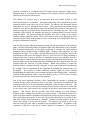
1
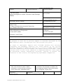
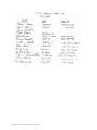
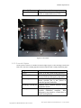
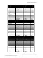
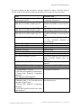
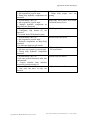
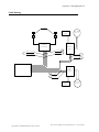
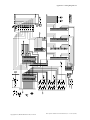
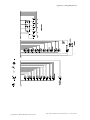
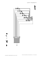
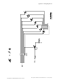
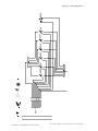
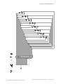
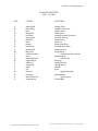
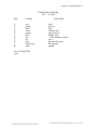
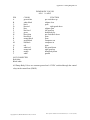
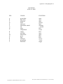
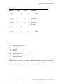
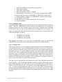
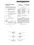
Appendix C: Wiring Diagrams 56
ROBOT POSITION
83569 22 AWG
PIN
COLOR
FUNCTION
A
B
C
D
E
F
G*
H
J
K
L
M
N
P
R
S
T
blue
orange/black
black/white
red/white
green
black/red
white/red
red
blue/red
red/black
white/black
shield
orange
black
blue/white
white
orange/red
ground
boom
turntable
spare
short arm
wrist
poppet
+ 10VDC
spare
spare
azimuth
shield
restraint
spare
spare
ground
long arm
NOT CONNECTED:
green/black
green/white
blue/black
•
•
•
Poppet valve added to shut off hydraulic flow to dump body. +12VDC for
control relay and valve power provided via the Robot PWM cable.
Poppet control relay coil is +12VDC common with a switched ground.
Poppet valve is common ground and +12VDC switched.
Poppet
Solenoid 17W
C ontrolR elay
W hite/R ed
ground
+12VD C
RobotJunction Box
Copyright 2011, AHMCT Research Center, UC Davis
DRV Operator’s Manual and Technical Reference (rev 1 0 June 30, 2000)