
1
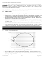
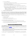
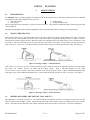
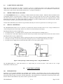
SENTINEL-PROX LR-2000 LONG-RANGE TAG AND CARD READER Installation & Operation Manual If you are new to the LR-2000 reader, or this is your first long-range installation, and you are having any concerns, we suggest that you call AWID Support at +1-408-825-1100 COPYRIGHT ACKNOWLEDGEMENTS The contents of this document are the property of Applied Wireless Identifications Group, Inc. (AWID) and are copyrighted. Any reproduction, in whole or in part, is strictly prohibited. For additional copies of this document please contact: Applied Wireless Identifications Group, Inc. 18300 Sutter Boulevard Morgan Hill, CA 95037 All rights are reserved. http://www.awid.com The information contained herein has been carefully checked and is believed to be accurate. No responsibility is assumed for inaccuracies. AWID reserves the right to make changes without prior notice. This document is not covered by any warranty, either expressed or implied. Any comments, corrections or additions to the contents of this document should be directed to AWID at the above address. Copyright 2008 by AWID. Printed in USA. All other trademarks are the property of their respective owners. NCC COMPLIANCE According to "Administrative Regulations on Low Power Radio Waves Radiated Devices" Without permission granted by the NCC, any company, enterprise, or user is not allowed to change frequency, enhance transmitting power or alter original characteristic as well as performance to a approved low power radio-frequency devices. The low power radiofrequency devices shall not influence aircraft security and interfere legal communications; If found, the user shall cease operating immediately until no interference is achieved. The said legal communications means radio communications is operated in compliance with the Telecommunications Act. The low power radio-frequency devices must be susceptible with the interference from legal communications or ISM radio wave radiated devices. NCC COMPLIANCE 經型式認證合格之低功率射頻電機,非經許可,公司、商號或使用者均不得擅自變更頻率、加大功率或變更原設計 之特性及功能。低功率射頻電機之使用不得影響飛航安全及干擾合法通信;經發現有干擾現象時,應立即停用,並 改善至無干擾時方得繼續使用。前項合法通信,指依電信法規定作業之無線電通信。低功率射頻電機須忍受合法通 信或工業、科學及醫療用電波輻射性電機設備之干擾。 LR-2000 Manual V1.4 Page 1 of 20 Table of Contents 1 2 INTRODUCTION ..............................................................................................2 SPECIFICATIONS ............................................................................................3 PART A INSTALLATION.................................................................................... 5 3 4 5 6 7 8 PREPARING FOR INSTALLATION ............................................................5 TESTING READER AND TAGS BEFORE INSTALLATION......................6 INSTALLING THE READER ..........................................................................7 INSTALLING THE CREDENTIALS...............................................................9 TESTING THE INSTALLED SYSTEM ........................................................10 INSTRUCTIONS FOR LR-2000HILOMA READER SET ...........................11 PART B PLANNING ........................................................................................... 12 9 10 APPLICATIONS ..............................................................................................12 PLANNING FACTORS ...................................................................................13 PART C REFERENCE........................................................................................ 16 11 12 TROUBLE-SHOOTING..................................................................................16 GLOSSARY ......................................................................................................20 NOTE: READ AND USE THIS MANUAL. FAILURE TO FOLLOW THE PLANNING AND INSTALLATION GUIDE MAY RESULT IN POOR PERFORMANCE AND EVEN CAUSE PERMANENT DAMAGE TO THE READER. THIS WILL VOID THE PRODUCT WARRANTY. REVISION HISTORY Version No. 1.4 Revised By LHH Date 27 August 2008 1 1.1 Sections Affected All Remarks Revised version INTRODUCTION GENERAL DESCRIPTION AWID's Sentinel-Prox LR-2000 Reader is an extra-long-range Radio Frequency Identification (RFID) reader that works with a selection of encoded credentials that may be clipped, hung, taped, adhered, fastened or held by hand inside or outside the vehicle. This reader comes with a unique combination of long read range, small size, and low power consumption. It has an internal power converter, allowing it to work with a wide range of supply inputs without affecting its performance. With a 12 volt DC supply, its current consumption is less than 1 ampere, making it suitable for a large selection of commercial power supplies. The LR-2000 reader has simultaneous Wiegand and RS-232 outputs. Its primary applications are automated parking garage entrance control, hands-free access control, vehicle identification, asset tracking, and asset management applications. 1.2 SPECIAL FEATURES • • • • • • • • • • Single small housing for reader electronics, RF module and antenna – blends into the landscape. Easy to install using a pan-and-tilt adjustable mounting bracket – available from AWID. Compatible with all commercial access control systems. Can be interfaced to a PC or to a special application controller. Shares code formats with other encoded cards, badges and tags. Allows mixing RFID products for several applications into an integrated system. Operates at low power level. Uses frequency-hopping technology in the 902-928 MHz band (standard). Passive tags assure small size, unlimited life, and easy mounting out of the driver’s vision. Users do not need an FCC license. LR-2000 Manual V1.4 Page 2 of 20 1.3 SUGGESTED APPLICATIONS • Automated vehicle identification for small cars, big trucks and trailers, and railcars. • Operation of vehicle gates and garage doors for authorized vehicles. • Tracking material assets in containers and on pallets. • Hands-free operation of doors and elevator call buttons for handicapped users (wheelchairs, gurneys). • Data collection using encoded cards and tags for input. 2 2.1 SPECIFICATIONS LR-2000 READER Input voltage: Between +7 volts DC and +15 volts DC Input current (peak): At 7 volts DC......................................... 1.5 amperes At 12 volts ............................................. 900 milliamperes At 15 volts ............................................. 700 milliamperes Read distance (guaranteed): With UHF tags and cards....................... From reader to 10 or 15 feet, depending upon tag type Frequency: Transmitter ............................................ 902 MHz to 928 MHz Receiver................................................. 902 MHz to 928 MHz Frequency-hopping channels: Number of channels............................... 50 channels (U.S.A. standard) Channel spacing..................................... 500 kHz Hopping sequence.................................. Pseudo-random pattern of channels 2.2 Output data interfaces: Wiegand electrical protocol, and RS-232 serial (simultaneous) Reader housing: Molded ABS plastic, on 1/8 inch aluminum back-plate; beige color Environment: Temperature for 100% duty cycle ......... -31 to 113 F (-35 to 45 C) Temperature for 50% duty cycle ........... -31 to 150 F (-35 to 65 C) Operating humidity................................ 0% to 95%, non-condensing Protection from weather Gasket at edge of cover, grommet at cable entrance (Use shield or housing when required.) CABLE EXITING FROM LR-2000 READER The cable that is integrated into the LR-2000 is 22 gauge, 10 conductors, stranded wire, color-coded insulation, not twisted pairs, overall 100% shielded, 30 inches long. (The connectors on the reader’s cable, when shipped, have no practical use. The installer removes these connectors and strips the insulation.) Color assignment: Red......................... DC power, positive Orange ................... RS-232 interface, Transmit Data Yellow ................... Enable RF transmission Green ..................... Wiegand interface, Data-0 Blue ....................... Data-Common Violet ..................... RS-232 interface, Receive Data Brown .................... (not used) Black...................... DC power, negative White ..................... Wiegand interface, Data-1 (No insulation)....... Drain wire 2.3 (Connect to controller’s Receive Data.) (Connect to reader’s black wire for arming.) (For either Wiegand or RS-232 interface. Do not tie to black wire.) (Connect to controller’s Transmit Data.) (Do not ground.) (Connect to shields of extended cables. Do not ground.) EXTENDED CABLE FROM READER TO PANEL AND POWER SUPPLY The LR-2000 reader requires cables with particular specifications. If the installation will use separate cables from the reader to the power supply, and from the reader to the reader input panel, use these specifications – Power cable: 18 gauge, 2 conductors, stranded wire, color-coded insulation, overall 100% shielded, high quality. Data cable: 22 gauge, 3 conductors, stranded wire, color-coded insulation, not twisted pairs, overall 100% shielded, high quality. LR-2000 Manual V1.4 Page 3 of 20 If power and data share the same cable, use these specifications – Combined cable: 18 gauge, 5 conductors, stranded wire, color-coded insulation, not twisted pairs, overall 100% shielded, high quality. The maximum allowable length of cable for Wiegand interface is 500 feet. The maximum specified length of the cable for RS-232 interface at 9,600 bits per second is 75 ft; this may be stretched for certain equipment to 500 ft or more using Cat 5 cable. Length of a separate power cable should not exceed 500 ft. Unlike proximity readers, the LR-2000 reader uses 2 separate wires for Power Negative (black) and for Data-Common (blue). These wires must not be connected to ground, nor to each other, nor to any other circuit. 2.4 POWER SUPPLY • The LR-2000 reader requires a separate, independent DC power supply for each reader. Do not connect the reader’s power wires (red and black) to the controller panel’s Positive Voltage and Ground terminals. • For multiple readers, you may use a multi-section DC supply if the sections are isolated electrically from each other, if each section has its own positive and negative terminals, and if each section has sufficient current rating for the LR-2000 reader. • The ideal power supply has current rating of about 1.5 times the current drawn by the LR-2000 reader. This helps to assure that the direct current remains quiet and steady. (See the table, below.) • The most common DC power supply has a nominal output voltage range of 12.0 volts to 13.8 volts (including power supplies for charging a back-up battery). To power a single LR-2000 reader, this power supply must have a current rating of 1.5 amperes or more. • The PS-12-3.3A plug-in power module in AWID’s LR-2000KIT Test & Set-up Kit is suitable for a single LR-2000 reader. • Certain commercial power supplies require excess current rating to assure quiet DC output, for example, 2.5 amperes at nominal 12 volts for a single reader. Contact AWID’s Technical Support for discussion of acceptable power supplies. Voltage Applied to Reader 7 volts DC 12 volts DC 15 volts DC 2.5 Current Load of Reader (maximum) 1.5 amperes 900 milliamperes 700 milliamperes Current Rating of Power Supply (minimum) 2.25 amperes 1.5 amperes 1.2 amperes READER’S EFFECTIVE RF FIELD Figure 1. Effective RF field for tags with LR-2000 reader. • The effective RF field is a figure of rotation of this diagram about its horizontal axis. Polarity of transmitted RF is circular. • Distance R is the read range for each AWID UHF tag or card. Guaranteed reading distance of 10 feet or 15 feet, depending upon the tag or card type, is less than R. LR-2000 Manual V1.4 Page 4 of 20 PART A 3 3.1 INSTALLATION PREPARING FOR INSTALLATION STUDY THE APPLICATION • • • • 3.2 Determine what your client wants. Discuss the requirements with AWID’s Technical Support. Visit the site; take photographs; draw diagrams; compare with similar installations. Look for unusual features. Study the Planning sections in this Manual to be sure that all factors have been considered. (See Part B.) Prepare a list of products and materials. Ask AWID’s Technical Support for ideas and review. GUIDELINES FOR THE INSTALLATION 1. Plan about one car length between the reader and the gate, where possible. This allows the vehicle to continue moving slowly as the tag is read and as the gate opens. 2. Select a reader location where the vehicle can move in a straight line for about one vehicle length as the tag is read. 3. Use an adjustable mount or bracket for pan and tilt-down aiming of the reader at the “sweet spot” where most of the credentials will be located in and on the vehicles. 4. Select a reader height that matches the location of credentials in and on the vehicles. See Section 9 for the popular combinations of reader mounting and vehicle types. 5. Locate the reader and credentials so that they are parallel to each other when the credentials are in the “sweet spot”. 6. Experiment with tag location in the vehicles. Move a tag to different locations, and try both orientations (“portrait” and “landscape”). Hook the HT-UHF Hangtag behind the inside rearview mirror. Clip the VT-UHF Visor Tag to the sun visor. Hold the CS-UHF or GR-UHF card inside the vehicle. Press the WS-UHF Windshield Tag against the windshield using a block of plastic foam. 7. Restrict the vehicles to a lane that is a single vehicle width. Use lane markings or cones or bollards to assure that vehicles stay close to the reader. 8. Instruct drivers to move at about 5 miles per hour as the tag is being read. Use signs and speed bumps at the “sweet spot”. 9. Watch for applications that suggest use of the LR-2000HiLoMA set. See Sections 9.5 & 9.6 for discussion of these cases. 3.3 WIRING – GOOD PRACTICES • Use only shielded cable for all readers, and for power, and for door locks or gate operator control. Unlike proximity readers, do not ground the LR-2000 reader’s cable shields. • Use a separate cable for each reader. Do not share the reader’s cable with wires that carry switched power, like door locks, or power to electrically noisy devices. (But data, TTL control, and dry-contact circuits may share the LR-2000’s cable.) • Do not connect the wires for two LR-2000 readers in parallel. Neither power nor data lines should be in parallel. (Parallel connection changes the pulse transmission characteristics, and prevents the host system from identifying the reader addresses individually.) • Connect the reader’s negative power wire (black) first, and positive power wire (red) last. Disconnect in the opposite order. • Remove power from the reader before making any wiring changes. • The Wiegand Data-0 and Data-1 lines should not share a twisted pair in the cable from the reader to the controller. If it is necessary to use twisted-pair cable, separate the data lines into two different pairs. For example, combine Negative Power (black) with Data-0 (green) in one twisted pair; and combine Positive Power (red) with Data-1 (white) in a second twisted pair. This minimizes cross-talk of Wiegand data pulses from one data line to the other. • The LR-2000 reader has no LED. The lens in the corner of the reader’s cover is a dummy. Use the LR-2000KIT instead. • The LR-2000 reader has 3 separate wires that serve as negative or common conductors – black for Power Negative, blue for Data-Common, and bare wire for cable shield Drain. These 3 wires must not be tied together anywhere in the system, and they must not be connected to ground anywhere. • The LR-2000 reader has wiring that is different from any proximity reader, or any other technology. You must follow the wiring diagrams and the instructions in this Manual to have the reader function correctly. • Unused wires from the reader’s cable must be taped or capped separately, so that they touch nothing. LR-2000 Manual V1.4 Page 5 of 20 4 4.1 TESTING READER AND TAGS BEFORE INSTALLATION INTRODUCTION Careful preparation is important for successful installation of AWID’s long-range readers and credentials. Simple bench-testing gives the installer confidence in the performance of the reader and the credentials, before the products are taken to the site. This testing isolates the reader and credentials from all other factors that contribute to performance of the final assembly. 4.2 ITEMS FOR BENCH TESTING AWID’s long-range reader and credentials are tested easily using only the items listed below. It is not necessary to interface the reader to a controller panel or reader-input module while conducting this test. • • • 4.3 • • LR-2000 reader (It does not contain an LED.) HT-UHF hangtag (26-bit code), or other tag * SP-6820-LR test unit, cable with 3 clips * PS-12-3.3A power module, cable with 2 clips * Wiring diagram, Figure 2 (below) * A component of the LR-2000KIT Test & Set-up Kit SUPPORTING THE READER The reader’s effective RF field, in which the long-range credentials can be detected, is maximized when there is no material in front of the reader or immediately to the sides of the reader. See the LR-2000 Effective RF Field diagram (Figure 1 on page 4). • Cut off the connector from the LR-2000 reader’s cable. unused wires separated from each other. • Hang the reader on a clear vertical surface in an open space, about 4 feet above the bench top, 4 feet from a side wall, and 4 feet below the ceiling. 4.4 Prepare the pigtails for the planned installation. Keep the WIRING FOR QUICK TEST • Connect the wires as shown in the wiring diagram, Figure 2 (below). • Be sure that unused wires are touching nothing. Do not cut off unused wires yet. • The first connection made is the reader’s black (negative power) wire. The last step is to plug in the DC power module. Figure 2. Wiring for quick test. 4.5 HOLDING THE TAG • Hold the test tag by the fingertips, with the hand behind the tag. Hold the tag at arm’s length, to the side of your body. Or … • Attach the test tag to a non-metal stick. Stand to the side of the reader’s RF field, and extend the tag into the reader’s field. • Hold the tag so that the face of the tag is approximately parallel with the reader’s face. (The reader is circular-polarized, so the credentials may be held at any angle – up-and-down, or side-to-side, or diagonal.) • Move the tag slowly though the effective RF field in front of the reader. Observe the edges of the zone and the point of maximum read range. The widest part of the zone is at about half of the maximum range. LR-2000 Manual V1.4 Page 6 of 20 4.6 TEST RESULTS • Proper operation of the reader and credential is indicated by a signal from the SP-6820-LR test unit each time that the credential is read. The LED changes briefly from Standby red to green, and a short beep (4 kHz tone) is heard. If the card or tag remains in the reader’s effective RF field, reads repeat at about 3 per second (factory default rate). • By moving the test tag in the space in front of the LR-2000 reader, the tester can map the extent of the effective RF field that is plotted in Figure 1. The reading distance should extend from the reader’s face to the guaranteed 10 feet or 15 feet with the test tags. The maximum diameter of the field’s cross-section, at half of the maximum range, should be about 6 feet. 5 5.1 INSTALLING THE READER INTRODUCTION Before installing the long-range readers and credentials, the rest of the application system is usually in place and tested. The system components for each entrance are commonly – • • • • • • • • • Computer with the application program (may be shared) Controller panel and reader-input module Gate or door operator (control and motor) Status switch for gate or door Request-to-exit switch or sensor Safety loop detector beyond the gate or door Buried loop to detect approaching vehicles Independent power source (not from the panel) Cables in conduit These installation instructions are for the LR-2000 reader’s Wiegand interface, using Data-0 and Data-1 wires (like most readers in access control). Note: LR-2000 wiring is not the same as a 125 kHz proximity reader. Follow the instructions in Section 5.4. If a serial interface using RS-232 protocol will be used, please download AWID’s Technical Reference on RS-232 Reader Interface. Collect these items to install the readers and credentials at the site – • LR-2000 readers • Mounting brackets and housings for readers • Power supplies, cables, and other material • • • UHF long-range tags and cards LR-2000KIT Test & Set-up Kit “LR-2000 Installation and Operation Manual” For technical support questions, visit For additional information, please visit AWID’s Web site www.awid.com. www.awid.com/support, or call 1-800-369-5533 (in the U.S.) or +1-408-825-1100 from 8:00 a.m. to 5:00 p.m. Pacific Time. 5.2 INSTALLING THE LR-2000 READER 1. Before starting installation at the site, plan the project. Study Sections 9 and 10 of this Manual. 2. Keep the reader assembled. Do not remove the aluminum plate behind the reader. Do not remove the plastic cover of the reader. Do not tighten or loosen the screws through the cover. This preserves your Warranty. 3. Attach the LR-911MB mounting bracket to the reader’s metal plate using 2 screws (1/4”-20, supplied). 4. To use a different mounting device, make an adapter plate or bracket that lets you fasten your mounting device to the two capture nuts at the center of the reader’s aluminum plate (1/4”-20 thread). Do not drill holes through the aluminum plate. In most applications the mounting device must allow pan-and-tilt adjustment for the reader. 5. Inspect the installation space. The reader may be mounted on any material including metal, but there must be open space in front of the reader and to its sides. There must be no material interfering with the reader’s effective RF field between the reader and the credentials’ location. 6. Measure the mounting height. It must relate to the location of the credentials when they are read at the “sweet spot”. For passenger vehicles it is typically at a height of 7 feet, to the side of the vehicle lane. 7. Be aware of the environment. Stay away from UHF communications devices. Avoid arc lighting fixtures by 3 or 4 feet. Aim neighboring readers so that their effective RF fields do not overlap. Mount readers for parallel lanes at least 12 feet apart, with their effective RF fields parallel to each other. Do not have LR-2000 readers facing each other (but “back-to-back” is OK). If mounted outdoors, provide a shield for sunlight and rain. 8. Test the site for electronic devices that may interfere with the LR-2000 reader. If interference is suspected, remove power from the other device while observing the LR-2000 reader’s performance. 9. Fasten the reader’s adjustable bracket or housing to the pole, post, pedestal, wall or ceiling. 10. Aim the reader at the location of the credentials (cards or tags) in the vehicle, when the credentials are at their reading distance from the reader. AWID guarantees minimum reading distance for its UHF credentials of 10 feet to 15 feet, depending upon the credential type. When the credentials are at this “sweet spot”, the reader and the credentials should be about parallel to each other. LR-2000 Manual V1.4 Page 7 of 20 5.3 WIRING THE READER (FOR WIEGAND INTERFACE -- Figure 3) 1. The cable between the LR-2000 reader and the controller panel should be (see complete specifications in Section 2.3) – • Stranded wire • Overall 100% shielded • 5 conductors for data & power • “Bunched” (not twisted-pair) * • High quality • 18 gauge for 2 power wires; 22 gauge for 3 Wiegand data wires • Color-coded insulation • Maximum length – 500 feet * If the cable is twisted pair, combine negative (black wire) with one data line (green or white wire) in one twisted pair, and combine DC power (red wire) with the other data line in a second twisted pair. This reduces crosstalk on the data lines. 2. From reader to power supply – Black wire for DC negative (first connection), and red wire for DC positive (last connection). Each reader’s power supply must be a separate supply (see specifications in Section 2.4) that is connected to nothing else. 3. Arming circuit – For continuous RF from the reader, connect its yellow wire to the black wire at the reader permanently. For control of the reader’s RF transmission by a vehicle sensor, connect the yellow wire to the relay contacts of the vehicle sensor. To disarm the reader (no RF transmission from the reader), let its yellow wire float. 4. From reader to panel’s reader input port – Green wire to Data-0, white wire to Data-1, and blue wire to Data-Common. For Data-Common, use a terminal with this name if available. If not, use this reader port’s “Common” or “Ground” terminal. 5. Drains for shields – Tie the reader’s uninsulated wire to the shields of the power and data cables. Do not ground the drain. 6. Grounds – Connect the panel’s ground to earth-ground only if instructed by the panel’s manufacturer. The LR-2000 reader and its power supply have no ground connection. Do not connect black, blue and drain wires together. 7. Unused wires – Keep the reader’s orange wire available to connect the LR-2000KIT’s test unit during set-up and tests. Wrap or cap the violet and brown wires separately. 8. Testing – While the cable terminations and junctions are still accessible, test the system for full function and performance. Then seal the terminations. Figure 3. Wiring for LR-2000 installation. 5.4 AIMING THE READER This step should be taken before the credentials are installed in or on the vehicles. From the LR-2000KIT Test & Set-up Kit, use the test unit, and one of the hand-held test tags, and the wiring diagram in Figure 2 on page 6. The reader does not have to be interfaced with the host system (but they may be connected together). Use the DC power module from the LR-2000KIT Test & Set-up Kit only if the independent DC power supply is not yet connected. 1. With no vehicle present, hold the hand-held test tag approximately where the vehicles’ credentials will be located when they are read. This is typically at about 10 feet or 15 feet from the reader, depending upon the selected tag type. 2. With the test tag held at this “sweet spot”, adjust the pan and tilt angles of the reader until the test unit indicates most robust reading. (Occasional reads will be missed normally because of the frequency-hopping feature of the LR-2000 reader.) 3. Map the outer limits of the reader’s effective RF field by moving the tag side-to-side slowly through the field, and along the axis from the reader’s face to the point of maximum range. LR-2000 Manual V1.4 Page 8 of 20 6 6.1 INSTALLING THE CREDENTIALS GENERAL RULES 1. The relationship between the reader’s location and aiming, and the location of the credentials (cards or tags) inside or outside the vehicle, is important for good performance. Plan the installation considering these factors before installation starts. 2. Start by testing the LR-2000 reader using the LR-2000KIT’s test unit and the hand-held test credentials, with no vehicle present at the reader. When good read range has been proved, proceed to mounting the cards and tags in or on the vehicles. 3. The “sweet spot” for reading a credential in or on the vehicle is typically 10 feet to 15 feet, measured between the face of the reader and the location of the credential. Note: The sweet spot is shorter than the credential’s rated “read range”, which is the total distance between the reader and the farthest point at which a hand-held credential can be detected. 4. At the sweet spot, the credential should face the reader, with clear line of sight (through the windshield is OK) to the reader, and with the credential and the reader about parallel to each other. Aim the reader at the sweet spot. 5. Orientation of a credential may be “portrait” or “landscape” or diagonal. Reading will be most active when either long edge of the credential is closest to the reader as the tag approaches the sweet spot. 6. Keep the hand and the body away from the cards and tags, to avoid blocking or reducing the card’s or tag’s RF field. 7. Before attaching WS-UHF tags to the windshield, clean the windshield near the tag, inside and outside. 8. To attach tags to side windows, select a window that does not lower into the door frame. Align tags with a reader at the side. 9. If necessary, turn off RF sources on the vehicle, such as anti-collision sensors and UHF communications gear. 10. Prevent buildup of snow over the tags. Use windshield wipers to remove water from the windshield. Near the ocean, wash the windshield near the credential to remove salt coating. 11. Prepare instructions for the users’ staff member who will oversee tag installation. Copy the suggestions in the sub-sections below for the appropriate card or tag, and copy the sub-section in Section 9 – Applications that matches this installation. 6.2 VT-UHF-0-0 VISOR TAGS 1. Mount the reader, usually over the driver’s side of the vehicle, or at the left side of the lane. 2. With the visor raised, clip the tag over the upper edge of the visor. The tag faces the driver. 3. As the vehicle approaches the reader’s sweet spot, lower the visor so that the tag faces the reader and is parallel to the reader. 4. When the gate or door operation starts, swing the visor back to its raised position. 6.3 HT-UHF-0-0 HANGTAGS 1. For hanging tag, mount the reader over the center of the lane. For hand-held tag, mount the reader at the left side of the lane. 2. Hook the hangtag over the stem that fastens the inside rearview mirror to the windshield. Either side of the hangtag may face the windshield. 3. The hangtag may be read either by leaving the tag hanging from the mirror’s stem, or by holding the tag between the fingers at the hook-end of the tag, with the tag facing the reader. 6.4 CS-UHF-0-0 CLAMSHELL BADGE and GR-UHF-0-0 GRAPHICS CARD 1. Mount the reader so that it faces the card when the driver holds it in the sweet spot. 2. Present the card to the reader. Keep the fingers at the edge of the card. Hold the card parallel to the face of the reader. 6.5 RV-UHF-0-0 REARVIEW MIRROR TAG 1. Peel off the label that covers the tag’s adhesive backing. Attach the tag to the housing of the inside rearview mirror, facing the windshield, at the driver’s side of the stem that supports the mirror. 2. Mount the reader so that it is aimed at the tags at their “sweet spot”. The reader’s face should be about parallel to the tags. 6.6 WS-UHF-0-0 WINDSHIELD TAG 1. Mount the reader so that it faces the WS-UHF tag at the “sweet spot” reading location. See Figures 4 and 5 for typical uses. 2. Move the vehicle so that the windshield is at the reading distance. Press the plastic-film side of the WS-UHF tag flat against the inside of the windshield. Use a hand-sized block of plastic foam (flexible but firm), 2 inches thick, to press the tag. LR-2000 Manual V1.4 Page 9 of 20 3. Test the tag at different locations inside the windshield. Try high and low, several inches from the vehicle’s door pillar, in “portrait” and “landscape” orientation. Avoid embedded wires, metal coating, dark tinting, RF emitting devices. If reading distance is too short, use a different AWID UHF card or tag. 4. Peel the plastic film off the tag. Press the tag’s adhesive flat against the inside of the windshield. This is a one-time application. The tag will not work after it is pulled from its original position. The tag can not be moved between vehicles. 5. WS-UHF tags will not read if held in the fingers, or carried, or taped. It reads only when adhered to the windshield glass. 6.7 MT-UHF-0-0 METAL-MOUNT TAG 1. Mount the reader so that it faces the MT tag at the “sweet spot” reading location. See Figure 6 for an example at the left side. 2. The MT tag may be hand-held, or attached inside or outside the vehicle. Attachment may be permanent or temporary. Inside the vehicle, use Velcro dots or the tag’s adhesive. Outside, use plastic screws or rivets, or adhesive, or sealant at the edges. 3. The tag must remain flat when held or attached. Do not hold or cover the tag between the two lines molded in the plastic. 4. Try vertical and horizontal orientation. Outside, vertical orientation may give best reading. Face the tag parallel to the reader. 5. Test the tag. Then finish installation by snapping the screw-hole plugs in place, for security and good appearance. 7 7.1 TESTING THE INSTALLED SYSTEM INTRODUCTION Install the system’s components, and apply power to all components. The LR-2000 reader and the UHF credentials may be tested in several ways that look at isolated parts of the system, and at the integrated system. This helps to assure that the complete system is functioning normally, and to identify a problem area, if any. (See Section 11 – Trouble-Shooting for solutions to particular problems.) 7.2 TESTING AWID’S PRODUCTS (ISOLATED) At any time the LR-2000 reader may be disconnected from the other components of the system, and the performance of the reader and the credentials tested by themselves. 1. Disconnect the power supply cable and the data cable from the reader. Break these circuits at the reader, not at the power supply or at the controller panel, so that problems with the cables and junctions can be detected also. 2. Use the LR-2000KIT Test & Set-up Kit at the LR-2000 reader. Follow the instructions in Section 4, but keep the reader installed and the cards and tags mounted normally. 3. If the test unit indicates normal reader performance using the hand-held test tag, continue testing using the UHF cards and tags that are mounted in the vehicles. 4. If the reader is not operating, contact your source of the AWID products for a Return Material Authorization (RMA). 5. When the LR-2000KIT indicates normal operation of the reader and credentials, connect other components of the application system one-by-one, watching for recurrence of the problem. Continue to use the LR-2000KIT as an indicator for the LR-2000 reader while the system is reconnected. 7.3 TESTING OUTPUT OF THE LR-2000 READER The LR-2000 reader has two data outputs – Wiegand and RS-232. Wiegand is commonly used for access control systems including automated vehicle identification. RS-232 is suited for commercial systems like truck scales and supply chain management. There are simple techniques that show the condition of the reader’s data interfaces 1. To test the reader’s Wiegand output: • Interface the reader’s 3 Wiegand data lines to this system’s controller, or • Interface the reader’s 3 Wiegand data lines to a different access control system that works normally with other readers and cards, or • Connect a test, display or enrollment device, such as Cypress Computer Systems’ WDG-5912 Keyboard Data Wedge, or • Connect the leads for a dual-trace oscilloscope suitable for AWID’s data output (40 microseconds pulse width, 2,000 microseconds interpulse spacing) between the reader’s Data-0 and Data-Common wires, and between Data-1 and Data-Common wires. LR-2000 Manual V1.4 Page 10 of 20 2. To test the reader’s RS-232 output: • Interface the reader’s 3 RS-232 data lines to the system’s controller, or • Interface the reader’s 3 RS-232 data lines to a different commercial system that works normally with other readers and cards, or with other RS-232 output devices, or • Clip the test unit from AWID’s LR-2000KIT Test & Set-up Kit to the LR-2000 reader, or • Interface the reader’s 3 RS-232 data lines to the serial port of a PC, and run the Windows HyperTerminal program *, or • Connect the leads for a single-trace oscilloscope suitable for AWID’s data output (9,600 bits per second) between the reader’s Transmit Data and Data Common wires. * 7.4 In Microsoft Windows, the path is: Start Æ Programs Æ Accessories Æ Communications Æ HyperTerminal Æ Hypertrm.exe. Configuration is 9,600 bits per second, 1 start bit, 8 data bits, 1 stop bit, no parity, ASCII emulation, flow control = any. To open the port and start HyperTerminal, click on the Call tab at the top of the window, and select the option “Start Call”. TESTING AN APPLICATION SYSTEM When the LR-2000 reader is interfaced to the reader input port of the application system, the format of displayed data depends upon the programming of the system. In a typical access control or automated vehicle identification system, the program allows selection of a code format that replicates the Wiegand-style encoding that AWID has programmed into the credentials. Therefore the system’s monitor may display the code data in the same data fields, and the same number system (decimal), that AWID uses for its encoding. Testing may be as simple as reading the decimal values of the credential’s data fields on the monitor. If the system’s monitor indicates that data are received from the reader but not recognized by the host (“Code format error”, “Facility code error”, “Parity error”, etc.) – • Check the host’s programming. • Check the reader’s output. • Check the wiring between the reader and the controller. • Check the credential’s code on a different reader or on a different system. If the system’s monitor indicates no data input from the reader – • Test the LR-2000 reader and the credential by interfacing to a different controller that is known to work normally. • Test the system by connecting the LR-2000 reader directly to the controller’s reader port, bypassing the cable and junctions. • Test the system’s input using a different reader and compatible card or tag. 8 INSTRUCTIONS FOR LR-2000HiLoMA READER SET AWID’s LR-2000HiLoMA is a set of two units that work together at a reader location. One unit is a Master Reader that controls the alternation of RF transmission between the two units. The second unit is a Remote Antenna, in an identical housing. The two units are interconnected by a coaxial cable. Instructions for installing the LR-2000HiLoMA reader set can be downloaded from the public documents in AWID’s Web site, www.awid.com. • Position: The master reader and the remote antenna may be in either position at the site. The deciding factor may be the position of the master reader that results in the easiest or shortest cabling. • Separation: AWID supplies a 6 foot long coaxial cable to connect the remote antenna to the master reader. When installed on brackets, the practical maximum separation between the master reader and the remote antenna is about 4 feet. Do not attempt to substitute a longer cable because of electrical loss in the cable. • Accessories: All accessories for the LR-2000 reader apply also to the LR-2000HiLoMA reader set. Use the same LR-2000KIT. • Reference Documents: LR-2000 Manual o LR-2000HiLoMA Installation Sheet. o Technical Reference issues for description, applications, etc. V1.4 Page 11 of 20 PART B 9 9.1 PLANNING APPLICATIONS INTRODUCTION The LR-2000 reader is especially designed for Automated Vehicle Identification (AVI). The chief variables that must be considered in planning the readers and credentials for the system are – • Lane characteristics • Reader location • Vehicle types • Credential characteristics The most important factors in planning a system are listed in Section 3.2. These must be considered carefully when laying out the plan for the installation. The following paragraphs describe particular applications and recommend reader location and tag type for each application. 9.2 SMALL VEHICLES ONLY If the reader is beside the lane, mount the reader as close to the edge of the lane as possible without damage to the reader. Choose the left side of the lane when possible, because this side is easier for the driver (in right-lane-driving countries) to judge the vehicle’s location relative to the left edge of the lane. Mount the reader on an adjustable bracket at a height of about 7 feet (for small cars, 6 feet may suffice). Attach or hold a UHF card or tag on the same side of the vehicle as the reader. Aim the reader at the tags when they are at the “sweet spot” – about 10 to 15 feet direct measurement from reader to tag as the vehicle approaches the reader. See Figure 4. Figure 4. Passenger vehicles -- reader beside lane. If the reader is centered above the lane, as inside a parking structure, mount the reader on an adjustable bracket at the lowest height that assures safe clearance between the reader and the highest vehicle. Hook a HT-UHF Hangtag over the inside rear-view mirror’s stem, or attach a UHF card to the back of the mirror facing the reader, or adhere a WS-UHF Windshield Tag to the upper center of the windshield, behind the mirror. Aim the reader at the tags when they are at the “sweet spot”. See Figure 5. Figure 5. Passenger vehicles -- reader above lane. 9.3 MIXED PASSENGER CARS, PICKUPS, VANS AND SUVs This application is a variation of Section 9.2. The reader beside the lane should be at about 7 feet height; the reader above the lane must be raised to clear the higher vehicles. Mount the tags and cards in small vehicles (sports cars) higher than in larger vehicles (SUVs). This places the tags and cards for all vehicles at about the same position relative to the reader. See Figure 4 and Figure 5. LR-2000 Manual V1.4 Page 12 of 20 9.4 LARGE TRUCKS AND BUSES Follow the general suggestions for vehicles in Sections 9.2 and 9.3, regarding the location of the reader mounting (beside the vehicle lane or over the center of the lane). Select the UHF card or tag that performs best in the combination of vehicle lanes, vehicle types, reader locations, and credentials characteristics. See Figure 4 and Figure 5. 9.5 MIXED VEHICLES OF ALL SIZES Use the LR-2000HiLoMA reader set, consisting of a Master Reader and a Remote Antenna. Mount the Master and Remote units on adjustable brackets at locations that are suitable for the type of tags and cards that will be used in the different vehicles. The reader brackets are usually supported by a single pole or pedestal, at heights that assure clear line of sight between the readers and the tags in all vehicles. (To reduce cable length, it is often best to mount the Master Reader lower than the Remote Antenna. Invert the units so that the coaxial connectors are at the bottom edge.) Aim the readers individually at the locations of tags and cards when they are at the sweet spots for the two vehicle types or sizes. 9.6 SPECIAL CONDITIONS The LR-2000HiLoMA reader set may be used also to spread out the effective RF field so that it covers a larger continuous area. (The read range does not become longer, but the cross-section size of the field may become larger.) Spreading the field horizontally is helpful when – • the vehicle lane turns – for example, the lane to the gate carries vehicles that turn off a through street, or • the vehicle lane is wider than a single lane, and some vehicles may be farther from the edge of the lane where the reader is located. Spreading the field vertically is helpful when – • tags are on a mix of small and large vehicles, requiring the readers to be aimed at different heights to read all tags, or • the reader is on a hill, or at the crest or dip in a hill, causing the tags to be at variable heights when they are read, or • the reader is near a change in the elevation of the lane surface, as at a curb or gutter or drain. Figure 6. Mixed passenger vehicles and large trucks -- using LR-2000HiLoMA. The LR-2000HiLoMA has a single data interface to a single reader port on the host panel. reader address in the host system. 10 10.1 This reader set uses a single PLANNING FACTORS INTRODUCTION Preparation for the LR-2000 installation pays dividends for the installer. The following topics cover the common questions. These topics apply generally to all forms of the LR-2000 reader. The environmental, electrical, interference and temperature range characteristics likewise apply to all forms of the LR-2000 reader. These characteristics are optimized if a buried-loop vehicle sensor arms the reader for RF transmission only when a vehicle is present at the reader. LR-2000 Manual V1.4 Page 13 of 20 10.2 ENVIRONMENT • Physical obstructions: The space where the reader will be mounted and aimed must be clear. • Weather: Provide shielding from direct rainfall (especially for LR-2000HiLoMA) and bright sunlight (especially if the reader is armed continually – yellow and black wires connected together permanently). • RFI: Avoid sources of radio frequency emission that might interfere with the reader. 10.3 LANE LAYOUT • Lane geometry: The lane should be straight for about a vehicle length where the reader reads the tag. Avoid sharp turns from through streets into short driveways. • Multiple lanes: Locate and aim readers so that they do not interfere with each other. pointed in the same direction, minimum centerline distance between the lanes is 12 feet. • Reader location: If readers are above the lanes, aim neighboring readers parallel to each other. If readers are on posts beside the lanes, aim the readers so that one reader is not aimed directly at the back of the neighboring reader. • Eliminating cross-reader interference: If readers must be close to each other so that their effective RF fields overlap, use the LR-2000HiLoMA reader set. This set of 2 units transmits RF alternatively, so that only one unit is active at any time. 10.4 For readers in parallel lanes, VEHICLE TYPES • All passenger car types: A single LR-2000 reader usually works for sport cars, sedans, SUVs and pickups, unless tags are in diverse locations on the vehicles. • Mixed small and large vehicles: The LR-2000HiLoMA reader set is available when cards and tags are spaced apart on vehicles of different sizes. • See Section 9 for details on reader selection for mixtures of vehicle types and sizes, and on reader location. 10.5 VEHICLE MOTION – IDEAL CONDITIONS • Vehicle in motion while the tag is read at the “sweet spot”. • Vehicle moving in a straight line while the tag is read. • Vehicle close to the reader location. • Vehicle’s tag about parallel to the reader’s front face when the tag is at the sweet spot. • Vehicle speed around 5 miles per hour for safety. (OK to experiment with higher speed.) 10.6 VEHICLE MOTION -- CONTROLS • To enforce the vehicle speed – use signs, speed bumps, traffic signals (red/green lights), gates, instructions for drivers, . • To enforce the vehicle path – use signs, painted stripes, cones, bollards, barriers, instructions for drivers. 10.7 READER TYPE • Typical case: Most applications are served well by a single LR-2000 for each vehicle lane. • Diverse vehicle sizes: For a combination of large and small vehicles in a lane, use LR-2000HiLoMA mounted over-under on the same post, for example. The “over” position may be for tags and cards in passenger cars. The “under” position may be for tags and cards on the side of buses and large trucks. • Turning lanes: To increase the horizontal spread in a tight turn, use LR-2000HiLoMA mounted side-by-side. Aim the reader and remote antenna somewhat apart. Test for continuity of field using the LR-2000KIT Test & Set-up Kit. 10.8 READER POSITION • Above the lane or beside it? – Either position works. If the reader is above the lane, the reader must be no higher than is required for vehicle clearance – typically less than 10 feet above the lane, unless the tags are all high on the vehicles. If the reader is beside the lane, the height and aiming depend on the type and location of tags on the vehicles. • Which side? – Either right or left side works. Left side (driver’s side) is better, because the driver finds it easier to align the vehicle with the left side of the lane, and with the reader if it is on the driver’s side. (This applies to right-lane-driving countries.) LR-2000 Manual V1.4 Page 14 of 20 10.9 READER MOUNTING • Adjustable bracket: The reader (and remote antenna) must be adjustable for both “pan and tilt” (in camera parlance – that is, horizontal and vertical) for proper aiming. See AWID’s LR-911MB (11 inch long arm, with a two-axis adjustable head). The installer may use a camera bracket effectively. • Fixed reader: The reader may be fastened directly to a wall, flat against the wall, in applications where the tags are on the side of vehicles facing the reader, as on buses and large trucks, and on wheelchairs, gurneys, etc. Distance between reader and tags should be about 5 feet to 10 feet. • Distance from lane: For a reader on a side post, locate the reader close to the edge of the lane, but safe from side-mirrors and errant drivers. For a reader above the lane, locate the reader as low as possible while leaving clearance for roof-racks, etc. • Reader aiming: The “sweet spot” for reading credentials is when the credential is typically about 10 feet to 15 feet from the reader. The goal is to have the tag about parallel to the reader’s face when the tags are read. 10.10 ELECTRIC POWER • Isolation: For each LR-2000 reader, or for each LR-2000HiLoMA set, provide an independent DC power supply that is not used for any other equipment. Use a separate DC power supply for each LR-2000 reader. A single power supply is used for LR-2000HiLoMA. • Voltage: Voltage at the reader must be between 7 volts and 15 volts DC. • Current: For a typical 12 volts to 13.8 volts supply, current rating must be at least 1.5 amperes. • Quality: The power supply must be linear-rated (that is, not switching) and regulated. 10.11 CABLE • Number of conductors: Depends on whether DC power for the reader is combined with data transmission in the same cable. Cables are usually specified in multiples of 2 conductors. • Power: 2 conductors in shielded cable. Use 18 gauge wires between the reader and the power supply. • Data: 3 conductors for either Wiegand interface or RS-232 interface. Use 22 gauge (18 gauge is OK). For Wiegand, use parallel wires – not twisted pairs. For RS-232, Cat 5, twisted or untwisted, is good. • Other specifications: Overall 100% shielded. Stranded wire. Color-coded insulation. Maximum length – 500 feet for Wiegand data and power; 75 feet for RS-232 data at 9,600 bits per second (up to 500 feet with certain terminal equipment). High quality. 10.12 MOUNTING THE TAGS AND CARDS • See the complete instructions for installing all credentials in Section 6. • Attachment: The different credentials have different requirements for mounting in or on the vehicles, or for holding by hand. Visor Tags use a molded clip for the sun visor. Hangtags hook on the inside rearview mirror or are held by fingers. Clamshell Badges and Graphics Cards are squeezed between a finger and thumb. Windshield Tags adhere inside the windshield glass. Rearview Mirror Tags adhere to the frame of the inside mirror, facing the windshield. • Orientation: The flat surface of the credential should be about parallel to the face of the reader. The hand should be behind the tag when the tag is held by the fingers. The tag may be held “portrait” or “landscape” relative to the reader; the angle does not matter. • Pre-installation testing: Hold the tag as intended in normal operation, or attach it temporarily (using masking tape, for example) in the planned location. Drive the vehicle slowly through the sweet spot. Observe the LR-2000KIT’s test unit for consistent reading. Adjust the reader’s position and aiming, and the credentials’ location, and the vehicle’s path and speed, as required. 10.13 ACCESSORIES • LR-2000KIT Test & Set-up Kit: Absolutely required. Installation may not be supportable by AWID if this Kit is not at the site. • Documents: Complete instructions set must be at the site with the installer. LR-2000 Manual V1.4 Page 15 of 20 10.14 AVOID … • “Toll tag mentality”: If the drivers are used to high-speed tollgates with active tags, they will feel restricted by a long-range reader using passive vehicle tags. Emphasize the desired goal of having the gate at the LR-2000 installation open, by driving at reasonable speed in a reasonable fashion near the reader. Point out the long-life and the low cost of passive cards and tags. • Metal in or on vehicle’s windows: Anti-glare tinting … reflective coating … metallic coating for automatic windshield wipers … embedded wires for defrost or antenna. These metal materials can reduce or block transmission from tags to reader. (“Lead glass” does not reduce performance.) • Electronics in the vehicle: Anti-collision sensors and certain communications gear, while they are active, may interfere with other RF transmission, including LR-2000’s tags and cards. However, most communications devices (cell phones, portable radios) and GPS have no effect. PART C 11 11.1 TROUBLE-SHOOTING PRODUCTS AND TOOLS AWID Products: LR-2000 long-range reader PS-12-3.3A DC power module * SP-6820-LR test unit * UHF cards or badges for LR-2000 * Adapter cable, 3 clips to 9-pin “D” * 11.2 REFERENCE RF-SD Detector for RF fields * “LR-2000 Installation Manual” Required Tools: Digital multimeter (20 VDC, 5 ADC) Common hand tools Back-up battery – 12 V, 7.5 A-hr Desirable Tools: Proximity reader (small) and card Oscilloscope, dual-trace, 915 MHz RF spectrum analyzer * Component of the LR-2000KIT SUMMARY The following 4 steps summarize the trouble-shooting procedure for the LR-2000 reader, from the simplest combination of products and test tools, to the complete access control system. The detailed trouble-shooting subjects start at Section 11.3. 1. Bench-testing at your shop: Test the reader using the instructions in Section 4 with Figure 2. Follow all steps. Goal: To be confident that the LR-2000 works by itself stand-alone, communicating only with the test tags and the test unit.. 2. Interfacing to a PC: Connect the reader’s RS-232 output to the serial input port of a PC. Run the Microsoft Windows HyperTerminal program. Watch for a column of data in rows of 18 hexadecimal characters. Do not mount the reader yet. Goal: To see consistent data from the test tag’s programmed code, at the programmed repetition rate. 3. Interfacing to the system: Connect the reader directly to the reader input port on the host system’s controller panel. This bypasses the cable and junctions between the reader and the panel. Goal: To see the reader transmit the tag’s code to the host system, with correct code consistently, and with access granted. 4. Connecting the complete system: Test the system as described in Section 7, using all components of the system. Goal: To confirm proper operation of the system in its final form. 11.3 GOOD IDEAS Do not “button up” the system mechanically or electrically until you have tested it thoroughly, and until you are confident that all components are working as specified. • Do not make final adjustments on the reader’s mounting yet. Keep the fastener’s accessible. • Do not cut and trim cables and wires yet. Keep all terminations available for measurements and for changes. Identify what the system is doing wrong, or what it isn’t doing right. • Isolate the system’s components. How does each component work alone? Decide which component is at fault. Keep the LR-2000KIT with you. It is absolutely necessary, and it may pay for itself in the first installation. • The Kit tells you when the reader reads a tag. It helps also in locating tags in the vehicle, and in aiming the reader. LR-2000 Manual V1.4 Page 16 of 20 11.4 POWER SUPPLY Use an independent power supply, not connected in any way to the controller panel or other system components. Do not connect other readers and other devices to the LR-2000 reader’s power supply. • Connect only a single LR-2000 reader to a power supply, and no other electrical load – not even a small proximity reader. • Have a different power supply for each LR-2000 reader. • Multiple readers may connect to a single power source if the DC outputs are isolated electrically from each other. Check the power supply’s specifications. • A separate DC power supply for every reader. Black and red wires connected only to this one power supply. • Voltage = between 7 volts and 15 volts DC (commonly 12.0 to 13.8 volts). • Current rating for a nominal 12 volt supply = at least 1.5 amperes for each LR-2000 reader. • AWID’s PS12-3.3A plug-in power module (in the LR-2000KIT) is suitable for a single LR-2000 reader. • For Altronix power supplies, select “Linear” rating and minimum current rating of 2.5 amperes. Model LPS3 is good. Calculate voltage drop between the power supply and the reader. • Measure voltage at the power supply with nothing connected to the supply. • Then measure voltage at the reader-end of the power cable before the reader is connected. • Then measure voltage at the reader when it is connected to the power supply (black and red wires). • Voltage drop is a combination of power supply regulation, and voltage drop in the cable. This should not exceed a few tenths of a volt. Check the reader’s current draw, and the cable’s wire gauge, and the power supply’s current rating. Measure DC current in the reader’s red wire. • Set the multimeter’s function to DC Amperes, and the range to 2 A or 5 A. • Disconnect the reader’s red wire from the power cable. • Insert the multimeter’s leads in series – positive lead toward the power supply, and negative lead toward the reader. • With voltage restored to the reader, its current is typically about 450 milliamperes in standby (no tag present), and about 900 milliamperes when the reader is processing a tag’s code. To evaluate the reader’s DC power supply and the power cable, substitute a back-up battery in place of the power supply. • Disconnect the reader from the independent DC power supply and the power cable. • Replace the power supply temporarily with a back-up battery (typically 12 volts, 7.5 ampere-hours, fully charged). This will power the LR-2000 reader for a working day. Alternative: Connect long clip leads to your truck’s battery. • A charged battery has perfect DC voltage quality and plenty of current rating. 11.5 CABLE Check the specifications of the cable between reader and panel, and between reader and power supply. They should be – • Stranded wires, color-coded insulation, overall 100% shielded, outside plastic sheath, high quality. • For power: 18 gauge wires, 2 conductors, twisted-pair is OK. • For data: 22 gauge wires, 3 conductors, not twisted-pair. • For power and data in same cable: 18 gauge, 5 conductors, not twisted-pair. • Maximum length for Wiegand interface (using the reader’s Data-0 and Data-1 lines) is 500 feet. For longer cable runs, use a Wiegand extender or a wireless transmitter. See Cypress Computer Systems’ Web site, www.cypressworld.com. • Maximum length for RS-232 serial interface is 75 feet at 9,600 bits per second. 500 feet is possible in special cases. If existing cable is twisted-pair (rather than “bunched” wires), run Data-0 and Data-1 through different twisted pairs. • Example: Run Data-0 and DC power positive in one twisted pair, and run Data-1 and DC power negative in another pair. Check the cable’s junctions and splices. • Be certain that they are solid, clean, dry, insulated, shielded and tested. • Do not let the cable shield touch metal conduit. Check metal conduit’s ground. Check for water inside conduit. If a cable problem is suspected, disconnect that cable, and run a temporary cable on the surface. • If the reader now works normally, pull new cable through the conduit, with no splices or junctions. If existing power cable has 22 gauge wires, connect spare wires in parallel for both DC positive and DC negative. LR-2000 Manual V1.4 Page 17 of 20 11.6 WIRING Wiring an LR-2000 reader is not the same as wiring other reader types. For the Wiegand interface, Data-0 and Data-1 lines are the same, but all other wires are different. Study the wiring diagram in Figure 3. Compare the actual wiring with this wiring diagram. The reader must be armed to transmit its RF field. To arm the reader, its yellow wire must be connected to its black wire. • To transmit RF only when a vehicle is present at the reader, use a buried loop or other vehicle sensor with relay contacts that connect the yellow and black wires temporarily. There must be no connection between the reader’s power supply and the host system’s panel – not even a ground connection. The power supply must be floating. The reader’s drain wire and the cables’ shields must be connected together, but they must not be grounded. These shields must be floating. (Induced noise is drained inside the LR-2000 reader.) Never connect 2 readers’ data lines in parallel on one reader input port. Always use a separate port for every reader. This preserves the data pulse shape, and allows each reader to have its own address in the host system. To bypass a problem in the cable, wire the LR-2000 reader directly to the panel’s reader input port. • Connect the reader’s 3 data wires directly to the panel’s reader input port – green to Data-0, white to Data-1, and blue to Data-Common on the same reader port. If there is no terminal labeled “Data-Common” on that reader port, connect the blue wire to the electrical Ground or Common terminal on that reader port, which serves as data-common also. • Use an independent DC power supply that meets AWID’s specifications fully (Section 11.4). Do not connect the reader’s black and red wires to the panel. • If the reader now operates normally, there may be a problem in the cable or its junctions, or in the conduit. Check the unused wires on the reader. • The unused wires must not touch each other or anything else. Tape them off singly. • The violet and brown wires are never used. They should be separately taped or capped. • The orange wire is used by the SP-6820-LR test unit (part of the LR-2000KIT Test & Set-up Kit). Keep this wire continually accessible for testing. For RS-232 serial interface, see AWID’s Technical Reference “RS-232 Interface”. Download it from www.awid.com/support 11.7 GROUNDING The LR-2000 reader has no grounded wires. Three wires are used as common or negative wires – black wire for power supply negative, blue wire for data-common, and drain (uninsulated) wire for shield draining. • These 3 wires must be wired correctly as shown in Figure 3. These 3 wires must not be connected to each other. • The reader’s yellow wire must be connected to the black wire to arm the reader for RF transmission. (See Section 11.6.) The reader’s power supply DC negative and the panel’s electrical ground must be kept separate. • Do not wire these two negatives together. Let the power supply’s secondary (DC) side float. • The panel and readers must be powered by different DC power supplies (or isolated outputs in a multi-channel supply). Check the reader’s drain wire (copper stranded wire without insulation). • The drain must be tied to the shield of the cables between the reader and the panel, and between the reader and the power supply – but the shields must not be grounded anywhere. The shields must float. (Draining occurs inside the reader.) Measure voltage between earth-ground and the system’s electrical ground. • Voltage must not exceed a few tenths of a volt in AC or DC. If it does, have a qualified electrical contractor check the 3-wire 120 VAC grounded power line and receptacle that feeds the DC power supply for both the panel and the reader. • Check that the 120 VAC green wire is at earth-ground. Check that the black and white AC wires are not reversed at a receptacle or junction. LR-2000 Manual V1.4 Page 18 of 20 11.8 11.9 ISOLATION Disconnect everything from the reader, except power. Move the reader to a remote location that has no electrical or RF noise. Use a backup battery (12 volts, 7.5 ampere-hours, fully charged) instead of the DC power supply. Test using the test unit and test tags from AWID’s LR-2000KIT Test & Set-up Kit. • Observe the reader’s performance by itself. Map the reader’s effective RF field by moving the tag slowly, side to side, gradually farther from the reader. Measure the maximum width of the field, and the farthest point where the tag reads. (This is the reader’s read range for that tag.) • Reconnect the rest of the system, one component at a time. Observe the reader’s performance at each step. What is it that makes the problem re-appear? Disconnect other devices near the problem reader. Observe performance of the LR-2000 reader by itself. • Remove power temporarily from proximity card readers, communications gear, intercoms, telephone-access controllers, arc-type lamps, PCs and monitors, transformers, motors, etc., that are near the LR-2000. • When the LR-2000 is connected directly to the system’s panel, disconnect other readers that are connected to that panel. REPLACEMENTS AND SUBSTITUTIONS Try a different reader in place of the problem reader: • • Is there a spare LR-2000 reader in your truck or at your shop? If so, use it in place of the original reader. • Do you have a different kind of reader, like a proximity reader and a compatible card or tag? If so, wire it into the panel in place of the LR-2000 reader. This may indicate a panel or system programming problem. Is there another LR-2000 reader, installed at this site, operating correctly? If so, interchange the two readers, and observe if the malfunction moves with the reader or stays at the original location? Do all tags give the same results? Try other tags and compare results. Interface the LR-2000 reader to an access control system that has tested good previously with a different reader. 11.10 ENVIRONMENT Remove power temporarily from all other equipment near the reader that generates magnetic fields or electric fields. • Look for communications antennas, PC monitors, arc-type lighting (including fluorescent), heavy electrical equipment (elevator motors, air conditioners, etc.), RF-type telephone access panels, other RF-type readers (even 125 kHz proximity readers), high-voltage 60 Hz power lines, etc. If the reader’s cable to the system has a junction inside the gate-motor housing, try removing power from the gate motor for the reader performance tests. Shield the reader from possible RF noise sources: • Form a large sheet of aluminum foil into a hemisphere around the reader’s rear and edges, to block environmental RF interference. Leave the aluminum foil open in front of the reader so that the reader can communicate with the test tags. Remove power from other LR-2000 readers that are less than 12 feet from the tested reader if they are aimed parallel (as in neighboring lanes at the gates), or less than 30 feet from the tested reader if they are aimed head-on toward the tested reader. • To see how the reader performs when it is removed from possible RF interference, do a “greenfield” test. • 11.11 Does the problem go away? Does the reader operate normally? Collect the LR-2000 reader, a back-up battery (or use your truck’s battery), a tag, and the test unit from the Test & Set-up Kit. Carry them to a remote site away from interfering devices. Test the reader’s performance under these conditions. HOST SYSTEM Observe messages on the PC monitor while the access control program is running. • If no message – there may be no data input from the reader to the panel, or from the reader input module to the controller. • If no message – there may be input data but not with the number of bits for which the system is programmed. For example, induced noise or data collision may add bits to the normal bit stream from the reader (commonly 26 bits). • If the message indicates bit-count error, or format error, or parity error, or facility code error, or non-valid identification number – find the source of the error. It may be incorrect programming of the host system, or of AWID’s cards or tags. • Watch the “Access denied: …” message. The listed reason for denying access may point to the cause of failure. LR-2000 Manual V1.4 Page 19 of 20 Program the host system to configure the data input from the readers. • Enter the code format of the tags (usually “26-bit Wiegand standard”), the tags’ facility code or site code, and (in the cardholders database) the ID number for the UHF tag. • Program your own test tag as an administrator, with top-priority level, access to all doors or gates, for all days and times. If the tag’s code data shown on the PC monitor are different from the code that is printed on the tag’s label – • Consistently wrong code for every read indicates that the tag is programmed wrong. Test the code from a different tag. • Randomly different code for every tag read indicates induced noise, intermittent wiring connection, or incorrect system grounding. Check for cable and wiring problems. If the problem is data collision in the host system because it can not process repeated code inputs quickly enough – o Use the reader’s arming circuit to transmit a single code read to the system. Touch the yellow wire to the black wire for only about one-half second. Does the system process the single code transmission correctly, every time? o Contact AWID about slowing the LR-2000 reader’s repetition read rate to prevent data collision in the host system. 11.12 11.13 POINTERS Keep the screws that fasten the aluminum plate to the reader’s plastic housing in place. Do not drill holes in the plate. Shield the LR-2000 from heavy rain, or from bright sunshine in hot weather. Use a suitable shade, hood or cabinet. Remove heavy snow from the face of the LR-2000 reader. Wipe snow and rain from the windshield. Wash salt coating from the windshield. Avoid metal films and embedded wires. TESTING TOOLS AND TECHNIQUES Digital multimeter (DMM): Absolutely necessary for voltage checks, and for current measurements at the reader. Oscilloscope: Useful for observing digital data output at the reader and input at the panel, and for analyzing the pulse shape. Test tags: Test the tags on a reader that is known to work well, to be sure that the tags work at their full rating. Reader substitution: Indicates whether the problem is in the reader or in the other components at the “bad” location. 12 GLOSSARY Controller panel ................. The electronic device that contains the input data port for the LR-2000 reader. For the Wiegand interface, this may be the access control system’s panel or board near the reader or gate operator, or the reader input module (RIM). For the RS-232 interface, this may be the system controller or a PC’s serial input port. Credential ........................... A token, such as a card or tag, that carries data to identify the individual token, and therefore to identify the person or vehicle by which the token is carried. Effective RF field ............... The three-dimensional space in front of the LR-2000 reader in which the vehicle tag can be read by the reader. The field is circularly polarized. It has a circular cross-section at every distance from the reader. See Figure 1 for a diagram of the effective RF field. Isolation .............................. A trouble-shooting technique that separates the components of the system temporarily so that performance of the components can be observed and measured individually. Lane..................................... The roadway that leads the vehicle past the reader and toward the gate. The ideal lane is a single vehicle width, or is marked by signs, painted stripes, cones, posts, bollards or barriers that remind the drivers to stay close to the reader. Power supply, switching .... A DC power supply whose DC output is generated by a circuit that produces interrupted current flow, at a rate of around 25 kilohertz. Read range The space along the axis of the reader’s effective RF field in which the tag can be read in hand-held testing. This extends from the LR-2000 reader’s face to the maximum distance – typically between 10 feet and 15 feet, depending upon the tag. (See Figure 1, “Effective RF field”.) Substitution ........................ A trouble-shooting technique that replaces a component of uncertain performance with a similar component that you know works well. Sweet spot ........................... The space in front of the LR-2000 reader where most credentials in a given installation are read. This is typically about 10 feet to 15 feet direct measurement from the face of the reader. At the sweet spot, the reader’s effective RF field has a cross-section with a diameter of about 3 feet or more. Tag orientation................... Direction (“landscape” or “portrait”) that tags are mounted in or on vehicles. If the reader looks down on a tag, landscape may give best reading. If the reader is at the side of the vehicle, portrait may be best. LR-2000 Manual V1.4 Page 20 of 20


![CS4070 Quick Reference Guide [French] P/N MN000763A02FR](http://vs1.manualzilla.com/store/data/006360309_1-ea04f68b5e72927234ea8d8bec3e4065-150x150.png)
