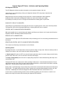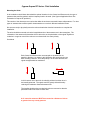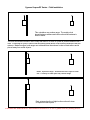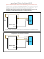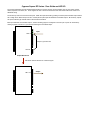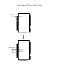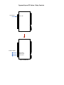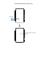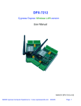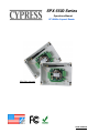
1
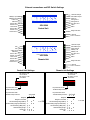
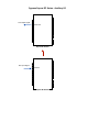
SPX-5500 Series
Operations Manual
RF 900Mhz Suprex® Reader
SPX-5511 pictured
SPX-5500SS
Cypress Suprex SPX-5500 Series
Overview:
The SPX-5500 series of RF Wireless solutions provide a wireless bridge from card readers with gates or door hardware to
most access control manufacturerʼs panels. The SPX or Suprex products include both the remote ( Door/Gate ) unit and
the central ( AC Panel ) unit.
Features:
-- Service mode for setup and configuration.
--“Quiet” protocol to conserve bandwidth and power
-- Field configurable reader formats
-- Multifunction indicator for determining operational status of the unit
-- Auxiliary I/O connections available for Door/Gate/Panel status signaling.
-- Multiplexing of RF bridge providing for additional door/gate on a single RF link. (future)
Electrical Specifications:
(Each Unit)
Supply Voltage#
Current#
#
#
#
8-16VDC
500mA
RF Specifications:
900Mhz frequency spread spectrum - no licensing required
Physical
Temp
Humidity
Power
Data I/O
SPX-5501/5511 - Weatherproof Enclosure
6.75” x 3.75” x 2.00”
Storage(-55˚C to + 150˚C)
Operating(-40˚C to +80˚C)
95% (non-condensing)
Input
Unreg Input 8 to 16 VDC* @ 300mA Max
Output
+5VDC @100mA
Interface
Reader -Wiegand, Strobed (Clock & Data), F/2F
LED - 0 - 30V
This complies with part 15 of the FCC rules
Operation is subject to the following two conditions:
(1) This device may not cause harmful interference, and
(2) this device must accept any interference received, including interference that may cause undesired operation.
Cypress Computer Systems 1778 Imlay City Rd
WWW.CypressWorld.com
[email protected]
Lapeer, MI 48446
Copyright @2010
External connections and DIP Switch Settings
1-Relay1 Input
2-Relay2 Input
3-Aux Out
4-Ground
5-RLY3 N.C.
6-RLY3 Com
7-RLY3 N.O.
8-RLY4 N.C.
9-RLY4 Com
10-RLY4 N.O.
1-D0/CLK Output
2-D1/Data Output
3-LED In
4-Prog Res 1
5-Prog Res 2
6-+5 VDC Out
7-N/C
8-N/C
RFX SPX-5500
- 5000 Series
Central Unit
Diagnostic LED
1-Ground
2-8 to 16 VDC In
N/C
N/C
3-Aux Input
4-Ground
5-RLY1 N.C.
6-RLY1 Com
7-RLY1 N.O.
8-RLY2 N.C.
9-RLY2 Com
10-RLY2 N.O.
1-D0/CLK Input
2-D1/Data Input
3-LED Output
4-Relay 3 In
5-Relay 4 In
6-+5 VDC Out
7-N/C
8-N/C
RFX SPX-5500
- 5000 Series
Remote Unit
Diagnostic LED
1-Ground
2-8 to 16 VDC In
Central Unit Settings
Remote Unit Settings
DIP Switch #1 ON
-Service Mode
DIP Switch #1 OFF
-Quiet Mode
DIP Switch #1 ON
-Service Mode
DIP Switch #1 OFF
-Quiet Mode
1 2 3 4 5 6 7 8
1 2 3 4 5 6 7 8
Dip switch #4 is ON
-Enable Pullup resistors
Dip switch #4 is ON
-Disable Pullup resistors
Dip switch #4 is OFF
-Enable Pullup resistors
Wiegand
Wiegand / No Filter
Strobed Rising Edge (MR-5)
Strobed Rising Edge (Dorad0 644)
Strobed Rising (Mag-Tek)
Strobed Falling Edge
Reserved
F2F
Dip switch #4 is OFF
-Disable Pullup resistors
Switch
6 7 8
0
1
2
3
4
5
6
7
x
x
x x
x
x
x
x x
x x x
x = ON
Wiegand
Wiegand / No Filter
Strobed Rising Edge (MR-5)
Strobed Rising Edge (Dorad0 644)
Strobed Rising (Mag-Tek)
Strobed Falling Edge
Reserved
F2F
0
1
2
3
4
5
6
7
Switch
6 7 8
x
x
x x
x
x
x
x x
x x x
x = ON
Quick Reference For Typical Connections
SPX-5000 Series Central Quick Reference
R1 IN
R1 Input
Controls
Strike on
Remote
D0/Clock
D1/Data
LED
D0/Clock Out
D1/Data Out
LED In
Access
Control
Panel
Switch #4 ON
Disable Pullup Resistors
Switch #4 OFF
Enable Pullup Resistors
Diagnostic LED
(-)
Ground
+8 to +16 VDC
(+)
Suprex RF Central
Typical Suprex Central Connections
DC
Power
Supply
1 2 3 4 5 6 7 8
Switch
6 7 8
Wiegand
Wiegand / No Filter
Strobed Rising Edge (MR-5)
Strobed Rising Edge (Dorad0 644)
Strobed Rising (Mag-Tek)
Strobed Falling Edge
Reserved
F2F
0
1
2
3
4
5
6
7
x
x
x x
x = ON
x
x
x
x x
x x x
SPX-5000 Remote
D0/Clock In
D1/Data In
LED Out
Door
Strike
LED
Card
Reader
R1 N.C.
R1 Com
R1 N.O.
Switch #4 OFF
Disable Pullup
Resistors
Diagnostic LED
(-)
Ground
+8 to +16 VDC
(+)
Suprex RF Remote
Typical Suprex Remote
Connections
Switch #4 ON
Enable Pullup Resistors
DC
Power
Supply
1 2 3 4 5 6 7 8
Wiegand
Wiegand / No Filter
Strobed Rising Edge (MR-5)
Strobed Rising Edge (Dorad0 644)
Strobed Rising (Mag-Tek)
Strobed Falling Edge
Reserved
F2F
Switch
6 7 8
0
1
2
3
4
5
6
7
x
x
x x
x
x
x
x x
x x x
x = ON
Cypress Suprex RF Series - Introduction
SPX-5000 Series:
This manual covers the operation and setup of the Cypress Suprex RF (5000 Series) units. Several
configurations are available with different enclosure and antenna options.
All of the units with the 5000 series part number will have the same operational functions and electrical
connections.
Features:
-- DES56 Encryption for secure communications
-- Units are factory configured as matched pairs, no field channel setting is required.
-- Service mode for setup and configuration.
--“Quiet” RF protocol to conserve bandwidth and power
-- Field configurable reader formats
-- Multifunction indicator for determining operational status of the unit
-- Auxiliary I/O connections available for Door/Gate/Panel status signaling.
Electrical Specifications:
(Each Unit)
Supply Voltage#
Current#
#
#
#
8-16VDC
500mA
Radio Specifications:
Frequency# #
#
Type ##
#
#
Transmit Power# #
Receive Sensitivity##
Interference Rejection#
900 MHz ISM band
Frequency Hopping Spread Spectrum
100mW
-110 dBm
70dB
Antenna Options and typical range:
Internal - Up to 500 feet #(SPX-5501)
Dipole - up to 1 Mile (SPX-5511)
Yagi - Up to 12,000 feet. (SPX-5531)
Distances given are typical line of sight. Actual distance will vary depending upon terrain, RF environment, and
height of antenna.
The units are shipped configured as a matched pair and are ready to plug in and operate.
The RF units are capable of operating with multiple pairs of units in the same environment. Units on different
channels can operate in the same area with minimal interference to each other. Unit channel selection is made
at the factory and no field settings are necessary. Up to 8 pairs of units can operate in the same area. A serial
number sticker will be present on the unit to indicate the paired units. Units matched as a pair will have the
same serial number or other identification labels.
Individual units should maintain a 24" separation distance from each other when installed in a central location.
Unpacking:
Cypress Suprex RF Series - Setup and Preinstallation
Remove covers from units and check interior for any shipping damage. Remove any packing material if present.
Inventory any included parts (depending on model) such as antennas, coax cables etc.
Bench Testing:
Before installing the units in the field they should be assembled and tested at a convenient “Bench top” location. This
will make it easier to verify / change settings and check operation when both units are visible at the same time.
It is also a chance to become familiar with the system if this is the first time using the Suprex system. It is much more
difficult to setup and test the units when they are several thousand feet apart.
Both units will need to have the antenna and a suitable power supply connected. For testing purposes, the units can
share the same power supply.
During initial setup it is helpful to use the Setup/Config mode. This allows a relative indication of the radio link quality
between the units.
Basic Bench Test:
1. Connect any antennas if the unit has a removable type antenna such as a dipole or Yagi.
2. Connect a suitable power supply to both units. Each unit should be provided with 8 - 16 volts DC and approx
300mA. Both units should be separated by a minimum of 24 inches.
3. Apply power. After about a 1 -2 second delay both units Diagnostic LED should indicate Green.
5. Touch a jumper wire from the Ground connection the the Relay 1 input on the Central unit. Relay #1 on the Remote
unit should activate with an audible click and the Diagnostic LEDs should flash green on both the Central and
Remote units.
6. Units are shipped from the factory set for the Wiegand data format. If a different format is required set the DIP switch
to the required reader and panel format.
7. If a reader and panel is accessible, connect the reader to the Remote unit and the Central unit to the panel and
verify that card reads are being accepted by the access control system. If any troubleshooting is necessary, it will be
easier to do with both units in close proximity to each other.
8. Once these steps are completed, the units are ready for installation it their permanent locations and final
commissioning as a system.
Cypress Suprex RF Series - Indicators and Operating Modes
LED Diagnostic Indicator:
The LED Diagnostic indicator provides information on the operational status of the unit.
If the units are not communicating, viewing the diagnostic indicator LEDʼs may help to determine the
nature of the problem.
When the Suprex units are operating correctly and have a valid communication channel between
the Remote and Central units, the Diagnostic indicators on each unit will flash green rapidly
(2-3 flashed per second) in Service / Config mode and illuminate a steady green in quiet mode.
DIAGNOSTIC LED NOT ILLUMINATED:
If the LED(s) are not illuminated on the unit(s) then the unit is not getting power or there is an electrical problem.
The Diagnostic LEDʼs will be illuminated Red/Green or flashing whenever power is applied.
CENTRAL UNIT FLASHING BETWEEN RED/GREEN:
With power applied and no communication path between the Remote and Central, the Central unit will flash the
diagnostic indicator alternately between Red and Green.
REMOTE UNIT ILLUMINATED RED:
The Remote unit will diagnostic LED will illuminate solid (not flashing) red if it is not receiving communication from
the Central.
REMOTE AND CENTRAL UNITS FLASHING BETWEEN RED/GREEN:
The Central is not Receiving communication from the Remote.
Operating modes:
By setting DIP switch 1 to the ON position, the unit is placed in Setup / Config mode. When the switch position is
changed, cycle power to the unit to make the switch change take effect.
In "Quiet" mode (DIP switch #1 OFF) the units will remain quiet unless there is a status change, and will slowly
poll each other about every 10 to 15 seconds to check the link integrity.
The Setup / Config mode places the units in a rapid polling sequence to allow troubleshooting and setup of the
communication link.
The Duprex RF units use a quiet protocol when operating in Quiet mode. Communication between the Central
and Remote unit only occurs when an event requires data transmission or contact needs to be made to maintain
supervision. The RF channel remains quiet most of the time.
During setup or troubleshooting it may be necessary to observe the communication link between the Central and
Remote units. The rapid polling used in the Setup / Config mode can help indicate whether the units can “See”
each other. Additionally the Central unit Diagnostic LED will indicate Red when communication is lost.
In some cases an optimal mounting location can be selected by operating one of the units on a small 12 volt
battery and moving the location while observing the diagnostic LED indicators.
Cypress Suprex RF Series - Field Installation
Mounting the Units:
A site evaluation should have determined the optimal locations for the Central and Remote units, the type of
antennas that would be needed, and the frequency band to be used. (See Cypress Application Note “Site
Evaluation for Duprex RF products”).
This section of the document covers units that utilize the enclosure mounted1/2 wave whip antenna. For other
types of antennas there will be specific documentation to cover their different installation issues.
We are now ready to physically mount the units and make the electrical connections to complete the
installation.
The units should be mounted so that the length dimension of the antennas are in the same plane. The
orientation of the antenna will determine what is referred to as the polarization of the signal. Significant
reduction in range can result if the units are not oriented with the same polarity.
See below.
Both Central and Remote units are arranged so the antennas are
parallel in direction. As shown in this illustration. We would say they are
both vertically polarized. Since the polarity is in the same direction, the
signal strength would be maximized.
In this instance one of the units is vertically polarized, and the other is
horizontally polarized. The signal would be greatly reduced thereby
reducing the maximum distance between units.
The installer should make sure that both units are mounted so that the
polarization will be the same for both units.
In all cases the antennas MUST be mounted at a distance of 20 cm
or greater from any nearby persons
Cypress Suprex RF Series - Field Installation
This orientation may reduce range. The metal pole is
placed between antenna and other unit and the antenna is
close to metal.
The units should be mounted in such a way that there is as clear of a path as possible between the 2
units. If mounting to a post or wall the unit should be placed where it has minimal interference with the
antenna. Maximum signal and ranges are achieved when the antenna is clear of obstructions and is
placed away from metal objects.
Better, improved range. Antenna has line of sight to other
unit. Proximity to metal pole may reduce range.
Best, antenna has line of sight to other unit and is clear
of adjacent metal objects.
In all cases the antennas MUST be mounted at a distance of 20 cm or greater from any nearby persons
Cypress Suprex RF Series - Door Strike and LED I/O
Note: The LED and Door Strike operation of the RF Suprex differs from previous Suprex versions.
To activate the relay on the Remote unit, connect as shown below. These connections can be used
to allow the Remote relay to operate a DOOR STRIKE, GATE, or other locking hardware. Refer to
following pages in this document for details of each I/O operation and connection.
There are two relays available for accessory outputs at the Remote end. Either relay can be used
to provide the Door Strike or Gate activation function. This example uses Relay 1.
Wiring Example - Door Strike Follows LED
R1 IN
R1 Input
Controls
Strike on
Remote
LED In
LED Signal
Ground
Access
Control
Panel
Suprex RF Central
Ground
Only Relay and LED Connections are shown for clarity, refer to previous diagrams for Power and Data connections.
Wiring Example - Door Strike does not follow LED
Strike Signal
R1 IN
LED In
LED Signal
Ground
Suprex RF Central
Ground
Access
Control
Panel
Cypress Suprex RF Series - Door Strike and LED I/O
The Cypress RFX-5000 provides additional data channels to support access control hardware such as door strikes, tamper
alarms, request to exit status, etc. These signals are sent to and from the Remote and Central units without the need to run
additional wiring.
The accessory control I/O use active low inputs. When the inputs are floating (nothing connected) the associated output will be
set to a high level. When the input is set to 0 Volts (Ground) the input will activate its associated output. All Accessory outputs
are Open Collector type and will switch to Ground when activated.
Each input will have an associated output. See the following pages for a diagram of each I/O pair. Inputs can be tested by
making a jumper connection to ground and monitoring the associated output.
Input
LED In
Jumper to ground to test
Ground
Suprex RF Central
Red arrow denotes direction of command signal
Output
LED Out
Suprex RF Remote
Cypress Suprex RF Series - Relay Controls
Input Signal
Relay 1 IN
Suprex RF Central
Contact Outputs
Relay 1 N.C
Relay 1 Com
Relay 1 N.O.
Suprex RF Remote
Cypress Suprex RF Series - Relay Controls
Input Signal
Relay 2 IN
Suprex RF Central
Contact Outputs
Relay 2 N.C
Relay 2 Com
Relay 2 N.O.
Suprex RF Remote
Cypress Suprex RF Series - Relay Controls
Contact Outputs
Relay 3 N.C
Relay 3 Com
Relay 3 N.O.
Suprex RF Central
Input Signal
Relay 3 IN
Suprex RF Remote
Relay 3 functions as an Alarm relay and monitors the condition of the communication link between
the Central and Remote units. Relay 3 is activated when power is applied and the communication link between
the Central and Remote is functioning. Relay 3 will become deactivated (Alarm condition)
when either the Relay 3 input on the remote is active OR the Remote unit is unable to communicate with the
Central unit.
Cypress Suprex RF Series - Relay Controls
Contact Outputs
Relay 4 N.C
Relay 4 Com
Relay 4 N.O.
Suprex RF Central
Input Signal (5Volts DC Maximum)
Relay 4 IN
Suprex RF Remote
Cypress Suprex RF Series - Auxillary I/O
Aux Output Signal
AUX OUT
Suprex RF Central
Aux Input Signal
AUX IN
Suprex RF Remote