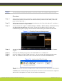
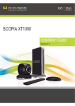
1
SCOPIA XT1000
Administrator Guide
Version 2.0
© 2000-2010 RADVISION Ltd. All intellectual property rights in this publication are owned by RADVISION Ltd and are
protected by United States copyright laws, other applicable copyright laws and international treaty provisions.
RADVISION Ltd retains all rights not expressly granted.
This publication is RADVISION confidential. No part of this publication may be reproduced in any form whatsoever or used
to make any derivative work without prior written approval by RADVISION Ltd.
No representation of warranties for fitness for any purpose other than what is specifically mentioned in this guide is made
either by RADVISION Ltd or its agents.
RADVISION Ltd reserves the right to revise this publication and make changes without obligation to notify any person of
such revisions or changes. RADVISION Ltd may make improvements or changes in the product(s) and/or the program(s)
described in this documentation at any time.
If there is any software on removable media described in this publication, it is furnished under a license agreement
included with the product as a separate document. If you are unable to locate a copy, please contact RADVISION Ltd and
a copy will be provided to you.
Unless otherwise indicated, RADVISION registered trademarks are registered in the United States and other territories.
All registered trademarks recognized.
For further information contact RADVISION or your local distributor or reseller.
Administrator Guide for SCOPIA XT1000 Version 2.0, September 2010
http://www.radvision.com
RADVISION | Administrator Guide for SCOPIA XT1000 Version 2.0
Chapter '' | 2
Table of Contents
1
Architecture Considerations
About the SCOPIA XT1000 Series .......................................................................... 1
SCOPIA XT1000 Series as Endpoints ....................................................................... 1
SCOPIA XT1000 Series as Embedded MCUs............................................................... 2
Embedded MCUs and SCOPIA XT Desktop ................................................................ 4
Firewall/NAT Support ....................................................................................... 4
ISDN Connectivity ............................................................................................ 5
Implementing External Control............................................................................ 5
2
Initial Configuration
Useful Documentation ...................................................................................... 7
Registering the SCOPIA XT1000 ............................................................................ 7
Enabling the Software License............................................................................. 8
Enabling the License at Setup........................................................................ 8
Enabling the Temporary License..................................................................... 9
Enabling the License from the Codec Unit Web Page ............................................ 9
Enabling the License from the Utilities Page .................................................... 12
Installing and Enabling an Option License ....................................................... 13
Setting the User Interface Language ................................................................... 14
Using the Quick Setup Wizard ........................................................................... 14
Setting the Country and Language ................................................................ 14
Adjusting the Image Size............................................................................ 14
Setting Date and Time............................................................................... 16
Setting the Codec Unit Display Name............................................................. 16
RADVISION | Administrator Guide for SCOPIA XT1000 Version 2.0
Table of Contents| i
Network Settings ..................................................................................... 17
Setting the Administrator/User Password.............................................................. 18
Setting System Preferences .............................................................................. 18
Setting Date and Time............................................................................... 18
Setting the Time Zone ............................................................................... 19
Setting Regional Data................................................................................ 20
Pairing a Remote Control Unit with a Codec Unit............................................... 21
Enabling the Screen Saver .......................................................................... 22
Configuring Video Connections .......................................................................... 22
Configuring the Camera ............................................................................. 22
General Settings ................................................................................ 22
Configuring the Camera(s) .................................................................... 23
Configuring Other Video Equipment......................................................... 24
Configuring the Monitor ............................................................................. 24
General Settings ................................................................................ 25
Graphic Adjustment............................................................................ 26
Configuring Monitor Layouts .................................................................. 26
Configuring Audio Connections .......................................................................... 27
Configuring the Microphone Array Pod(s) ........................................................ 27
Configuring Other Audio Inputs .................................................................... 28
Configuring the EchoCanceller ..................................................................... 29
Configuring Audio Outputs.......................................................................... 30
Settings for HDMI Recording ........................................................................ 30
Upgrading to the XT1000 with Embedded MCU ....................................................... 31
Configuring Network Settings ............................................................................ 32
Configuring Preferences............................................................................. 32
General Network Settings ..................................................................... 32
Configuring Dynamic Ports .................................................................... 32
Configuring NAT/Firewall Traversal Use .................................................... 36
Configuring Quality of Service (QoS) ........................................................ 37
Configuring GLAN/LAN Properties ................................................................. 38
Configuring Network Addresses .............................................................. 38
Configuring Bandwidths ....................................................................... 39
Configuring MTU Parameters ................................................................. 40
Configuring Gatekeeper Use........................................................................ 41
General Settings ................................................................................ 41
Settings for Gatekeeper Use.................................................................. 41
RADVISION | Administrator Guide for SCOPIA XT1000 Version 2.0
Table of Contents| ii
Configuring Gateway Use ........................................................................... 43
Configuring DNS Server Use......................................................................... 43
Configuring SIP Server Use.......................................................................... 43
Configuring LDAP Server Use ....................................................................... 44
Configuring ISDN Connectivity...................................................................... 46
Configuring Call Properties ............................................................................... 49
General Settings...................................................................................... 49
Audio/Video Compatibility with Older Systems ................................................. 50
Configuring IP Settings .............................................................................. 50
Configuring Video Quality........................................................................... 51
Securing Calls ............................................................................................... 52
3
Maintenance Tasks
System Remote Management............................................................................. 53
Configuring the Codec Unit for Remote Upgrade ..................................................... 56
Upgrading the Software................................................................................... 57
Managing the Codec Unit with AT Commands ......................................................... 59
Configuring the System for SNMP Management ....................................................... 60
Importing/Exporting Configuration Files ............................................................... 61
4
Troubleshooting
System Management Using VNC.......................................................................... 63
Activating Recovery Mode ................................................................................ 64
Using the Diagnostics Feature............................................................................ 69
FAQs .......................................................................................................... 69
12 Mbps License ...................................................................................... 69
Audio ................................................................................................... 69
Calls .................................................................................................... 69
Call Performance ..................................................................................... 70
Graphics ............................................................................................... 70
IP Address ............................................................................................. 71
Monitor and Power On ............................................................................... 71
PC Presentation....................................................................................... 72
Remote Control Unit ................................................................................. 72
RADVISION | Administrator Guide for SCOPIA XT1000 Version 2.0
Table of Contents| iii
Video and Camera ................................................................................... 72
Contacting Support ........................................................................................ 72
RADVISION | Administrator Guide for SCOPIA XT1000 Version 2.0
Table of Contents| iv
1
Architecture Considerations
About the SCOPIA XT1000 Series
The SCOPIA XT1000 Series incorporates the latest state-of-the-art video technology for room
conferencing, including support for dual stream 1080p video, high quality data sharing, high
quality full band audio and a high capacity embedded MCU.
Among its key features, SCOPIA XT1000 delivers support for two full High Definition (HD) 1080p
video streams as standard. It includes a PTZ (Pan-Tilt-Zoom) camera with 10x optical zoom for
viewing details, and wide-angle capability for capturing an entire group. The second video stream
can be used with an additional 1080p camera for visual coverage or with a PC for data sharing.
SCOPIA XT1000 supports high-resolution PC data sharing at 30fps, thus allowing presentations and
video clips to be shared with no quality loss.
The multipoint technology embedded in SCOPIA XT1000 provides the ability of hosting High
Definition (HD), Continuous Presence (CP) meetings with up to four or nine participants.
SCOPIA XT1000 provides full band audio encoding to ensure high-clarity audio transmission with
no loss of quality. Beam forming technology is used in the 3-way Microphone Pod to put the focus
on the speaker while isolating background noise. The ability to daisy-chain a second microphone
provides unparalleled large room coverage.
SCOPIA XT1000 Series as Endpoints
Figure 1-1 illustrates a topology in which the XT1000/XT1200 act as endpoints (or terminals):
• The MCU (e.g. SCOPIA Elite MCU) performs media processing for all connected terminals
(XT1000/XT1200, compatible 3rd party, SCOPIA VC240) regardless of their location and can
handle multiple conferences simultaneously. SCOPIA Elite MCU incorporates multi-party
1080p, 720p and H.264 Scalable Video Coding (SVC).
• SCOPIA VC240 integrates advanced video conferencing into a Samsung high resolution 24-inch
multimedia LCD monitor.
The XT1000 features the XT1000 Standard Camera. The XT1200 features a Sony Camera. Both
cameras are high end devices with state-of-the-art optics and full HD (1080p) support.
The Sony Camera provides better quality on average videocommunication condition and is
recommended when:
RADVISION | Administrator Guide for SCOPIA XT1000 Version 2.0
'Architecture Considerations' | 1
• High motion 720p60 capture is required. The Standard Camera does not support 60fps
capture.
• There are very low light conditions. In general, the Sony Camera captures better image in low
light conditions.
Figure 1-1 SCOPIA XT1000 Series as Endpoints
SCOPIA XT1000 Series as Embedded MCUs
The MCU capability is embedded in the SCOPIA XT1000 and can be activated by registering the
Codec Unit serial number and product key in the XT1000 web registration page reserved to SCOPIA
XT1000 purchasers. See http://www.radvision.com/XT1000.
The SCOPIA XT1000 HD Room System has the capability of deploying two levels of MCUs:
• SCOPIA XT1004 - Basic MCU level with up to 4 participants (1 Local and 3 Remote). Each
participant receives up to 720p and can send up to 448p.
• SCOPIA XT1009/XT1209 - Advanced MCU level with up to 9 Participants (1 Local and 8
Remote). Each participant receives up to 720p and can send up to 488p depending on the
selected CP layout. Only the Active Speaker can send up to 448p. SCOPIA XT1009 features the
XT1000 Standard Camera, while SCOPIA XT1209 features a Sony Camera.
RADVISION | Administrator Guide for SCOPIA XT1000 Version 2.0
'Architecture Considerations' | 2
Figure 1-2 SCOPIA XT1009/XT1209
The figure illustrates how the embedded MCU performs media processing for connected terminals
regardless of their location and handle multiple conferences simultaneously.
We recommend enabling the High Bandwidth Option (12Mbps) when using the embedded MCU. If
the High Bandwidth option is not enabled, the MCU will send out a lower resolution according to
the standard 4Mbps total bandwidth.
The embedded MCU can host Standard Definition (SD) and HD endpoints simultaneously. The
presence of SD endpoints does not affect the quality received by HD endpoints. SD endpoints will
receive SD video streams and HD endpoints will receive HD video streams. In the same way 4:3
and 16:9 video formats are included in the best possible way into the CP mosaic.
RADVISION | Administrator Guide for SCOPIA XT1000 Version 2.0
'Architecture Considerations' | 3
Embedded MCUs and SCOPIA XT Desktop
Built on the SCOPIA XT1000 HD room system with its high capacity embedded MCU, the SCOPIA XT
Desktop solution combines HD room system capabilities, embedded multi-party conferencing,
desktop conferencing and firewall traversal. The SCOPIA XT Desktop option is delivered on a CD
for installation on a separate server.
The solution enables remote users to easily connect to a meeting, relying only on the SCOPIA
XT1000 and its embedded MCU with no extra hardware to acquire, deploy and configure. A single
SCOPIA XT Desktop Server is deployed with a single XT1000 endpoint, utilizing the endpoint’s
embedded MCU. The Desktop Server will connect to one specific XT1000 endpoint and will be tied
to its hardware address.
The typical use case would be: a meeting is scheduled in a conference room with SCOPIA XT1000
and another site. A remote sales person wants to participate to the meeting. The remote user
opens his/her web browser, points it to SCOPIA XT1000 and connects to the meeting.
Firewall/NAT Support
SCOPIA XT1000 fully supports firewall and NAT traversal using one of these methods:
• Local Configuration of Firewall/NAT public address. When the system is installed in a NAT
environment, you can configure the NAT public IP address in the Codec Unit in several ways:
Manual setting, Automatic Discovery using HTTP, or Automatic Discovery using STUN. Once
configured, this Firewall/NAT public IP address is then used for all signalling configurations.
This approach works well in simple Firewall/NAT deployments, typically used by home or
small business routers, but requires further support to open ports on the Firewall/NAT server.
Consult your network administrator.
• H.460. H.460 is a H.323 extension to support firewall and NAT traversal. It is more robust than
the auto discovery approach and will traverse more complex network configurations. This
approach requires a Traversal Server, such as RADVISION Pathfinder, to be installed in the
network.
Third-party ITU compliant servers are also supported.
The Codec Unit does not implement a built-in H.460 server. A separate server is required as
the Codec Unit supports only the client side of H.460.
A further solution for firewall issues can be implemented using the LAN 10/100 port option. When
enabling the LAN port, the user will be allowed to connect the two adapters to different IP
networks: for example, LAN connected to the public network and GLAN to a private network.
Note:
When SCOPIA XT1000 is deployed in managed complex network scenarios and is registered to a
gatekeeper, the gatekeeper management policies will apply to both interfaces. Consult your
network administrator for any routing problem that may arise.
RADVISION | Administrator Guide for SCOPIA XT1000 Version 2.0
'Architecture Considerations' | 4
ISDN Connectivity
The SCOPIA XT1000 Series supports ISDN connectivity, allowing calls from endpoints to be routed
to the relevant conference using the SCOPIA BRI (Basic Rate Interface) and PRI (Primary Rate
Interface) gateways.
RADVISION has implemented a special pairing mechanism between the gateway and the endpoint
so that ISDN dialing is very simple. After pairing the systems, the participants place ISDN calls by
dialing the remote party ISDN number. The system automatically and transparently takes care of
setting the bit rate and call routing through the ISDN gateway.
A single gateway can serve multiple endpoints. For example, an organization needs to enable 5
endpoints with ISDN connectivity. Assuming the requested ISDN connectivity speed is 256bps, use
only one ISDN PRI gateway as it can support 5 concurrent calls of 256bps each.
With the gateway approach less communication lines are needed. As all gateways do not connect
at the same time and not all calls are ISDN, many more endpoints can share the same ISDN
connection and gateway.
Implementing External Control
The SCOPIA XT1000 has a feature-rich API. Using this API, integrators can implement AMX and
Creston applications to control the Codec Unit. The API is implemented as text commands over
the Ethernet interface. Contact RADVISION customer support for a copy of the API
documentations.
For the current release API support is available by using IP protocol over the Ethernet connection,
and not via the RS-232 serial port.
RADVISION | Administrator Guide for SCOPIA XT1000 Version 2.0
'Architecture Considerations' | 5
RADVISION | Administrator Guide for SCOPIA XT1000 Version 2.0
'Architecture Considerations' | 6
2
Initial Configuration
Useful Documentation
When configuring the system, consult the documentation RADVISION puts at your disposal:
• SCOPIA XT1000 User Guide, which explains how to operate the SCOPIA XT1000.
• Release Notes, for the latest software updates.
• SCOPIA XT1000 Specifications on the RADVISION web site.
• RADVISION web site at http://www.radvision.com/
Registering the SCOPIA XT1000
Procedure
Step 1
Step 2
Open the envelope that came with the SCOPIA XT1000.
Step 3
Step 4
On a computer, open a browser and navigate to http://www.radvision.com/XT1000.
Step 5
Step 6
Write down the license key and keep it in a safe place for future use.
Locate the serial number and the product key in the letter inside the envelope. The serial number
is printed on a label affixed at the back of the Codec Unit. You can find the user code (and the
serial number) by pressing
in any page.
Complete the online registration form and enter the serial number (or the user code) AND the
product key. The web registration form returns a license key.
Use the license key to enable the software (see Enabling the Software License page 8).
Note:
You can obtain other license keys in the same way, when you need them to enable optional
features in the Codec Unit.
RADVISION | Administrator Guide for SCOPIA XT1000 Version 2.0
'Initial Configuration' | 7
Enabling the Software License
Obtain your license key as explained in Registering the SCOPIA XT1000 page 7.
Enable the software license in either way:
• Locally from your terminal, by using the Remote Control Unit.
• Remotely, by using a web browser to access the SCOPIA XT1000 GUI (see Enabling the License
from the Codec Unit Web Page page 9).
You can use software versions V1.0.x without any license. Starting from Software Version V2.0,
you need an enabling license to upgrade a SCOPIA XT1000 with major or minor software versions.
You can also load a new software version into the system, but its functionalities will be freely
available only for a limited period of time. When this time expires, you will have to insert a
software enabling license to unblock system functionalities.
The current software release does not allow upgrading the software via web access. You need to
download the new software version file and run it on a PC as explained in Upgrading the Software
page 57.
Enabling the License at Setup
Procedure
Step 1
When you switch on the system for the first time, the display shows the Enable License page.
Select the language of your choice for the user interface.
Figure 2-1 Enable License Page
Step 2
Step 3
Insert the license key in the displayed page.
Press
Enable license.
RADVISION | Administrator Guide for SCOPIA XT1000 Version 2.0
'Initial Configuration' | 8
Enabling the Temporary License
Work with a temporary license for a limited period of time if you cannot obtain the license key
immediately.
Procedure
Step 1
After proceeding as described in Step 1 of Enabling the License at Setup page 8, press
Start.
Use the Codec Unit with full features for a time limited mode of 24 hours. The remaining
activation time is shown in the system area of the screen, next to the time.
Figure 2-2 Temporary License Timeout
Step 2
After the temporary work time expires, the display shows the Enable license page. Insert the
license key.
Figure 2-3 Enable license Page
Step 3
Press
Enable license.
Enabling the License from the Codec Unit Web Page
Procedure
Step 1
Step 2
Start a web browser on your PC (Internet Explorer V7).
Enable download management as described in Configuring the Codec Unit for Remote Upgrade
page 56.
RADVISION | Administrator Guide for SCOPIA XT1000 Version 2.0
'Initial Configuration' | 9
Step 3
Enter the IP address of Codec Unit in the address bar of the browser.
Figure 2-4 Web Access
Step 4
Once in this page select Settings > Utilities > Licenses.
Figure 2-5 Web Interface
RADVISION | Administrator Guide for SCOPIA XT1000 Version 2.0
'Initial Configuration' | 10
Step 5
Set the fields as required.
Figure 2-6 Enabling the License from the Web
Step 6
Step 7
Field Name
Description
Serial number
The serial number is printed on a label affixed at the back of the Codec Unit.
You can also find the serial number by pressing
in any page.
User code
Find the user code by pressing
Enable code
Enter the license key you received when registering the product.
in any page.
Press Enable license.
Press Close to close the screen.
RADVISION | Administrator Guide for SCOPIA XT1000 Version 2.0
'Initial Configuration' | 11
Enabling the License from the Utilities Page
Procedure
Step 1
From the Main Menu page scroll to Settings and press
administrator password (default is 1234).
Step 2
Step 3
Scroll to Utilities.
Step 4
Step 5
Enter the license key.
Administrator Settings. Enter the
Select Licenses.
Press
Save.
RADVISION | Administrator Guide for SCOPIA XT1000 Version 2.0
'Initial Configuration' | 12
Installing and Enabling an Option License
Table 2-1
SCOPIA XT1000 Software Options
Reference
Description
MCUs
55111-00002 SCOPIA XT1000 MCU4 Option
Adds 4 way 720p embedded MCU
55111-00003 SCOPIA XT1000 MCU9 Option
Adds 9 way 720p embedded MCU
55111-00012 SCOPIA XT1000 MCU4->9
MCU 4 to 9 Upgrade
Bandwidth and Network
55111-00004 SCOPIA XT1000 12MBPS
Option
Increases total bandwidth to 12Mbps
55111-00016 SCOPIA XT1000 2nd LAN port
Enables 10/100 LAN port
SCOPIA Desktop
88111-00001 SCOPIA XT Desktop Option for To activate a SCOPIA XT Desktop 4 ports license,
MCU4
you must have an MCU 4 port license.
88111-00002 SCOPIA XT Desktop Option for To activate a SCOPIA XT Desktop 9 port license, you
MCU9
must have an MCU 9 port license.
88111-00003 Upgrade SCOPIA XT Desktop 4 SCOPIA XT Desktop 4 to 9 upgrade
to Desktop 9
SCOPIA Control
55111-00017 SCOPIA XT1000 Control
To control SCOPIA XT1000 using the SCOPIA Control
Application (iPad).
Procedure
Step 1
Open the envelope that you obtained when you bought an option, or refer to the e-mail you
received after purchasing your option.
Step 2
Locate the option key in the letter. Locate the serial number on the Codec Unit or the user code
you received with the purchase. You can also retrieve the user code and serial number in the
System Info page that appears when you press
on the Remote Control Unit.
Step 3
Step 4
On a computer, open a browser and navigate to http://www.radvision.com/XT1000.
Step 5
Step 6
Write down the license key and keep it in a safe place for future use.
Complete the online registration form and enter the serial number or the user code and the option
key. The Web registration form returns a license key.
Use the license key to enable the software or the option you bought. See Enabling the License
from the Codec Unit Web Page page 9 or Enabling the License from the Utilities Page page 12.
RADVISION | Administrator Guide for SCOPIA XT1000 Version 2.0
'Initial Configuration' | 13
Setting the User Interface Language
There are four ways of setting the language of the interface:
• When enabling the software license
• In Page 1/6 of the Quick Setup Wizard
• In Administrator settings > System > Location > General
• In Settings > User settings > General.
Using the Quick Setup Wizard
A quick setup wizard will assist you in this first approach to the system.
The quick setup will show more pages, allowing you to set some useful parameters for basic
system management. Your system administrator might already have set these parameters for you.
You might also use the quick setup wizard after:
• Restoring default settings
• Re-installing software
Setting the Country and Language
Procedure
Step 1
Use the arrow keys to select the Country in which the system is located and the preferred GUI
Language.
Step 2
Press
Next to access the next display.
Adjusting the Image Size
If the display appears cropped on your monitor, you may need to adjust the image size the system
sends you.
For an optimal video experience, some heuristic suggestions might help to configure the monitor:
RADVISION | Administrator Guide for SCOPIA XT1000 Version 2.0
'Initial Configuration' | 14
• Contrast, Brightness and Sharpness of the monitor can be configured in self-view, in order to
define the display settings in optimal conditions.
• If available, true pixel-to-pixel representation for Full HD resolution usually gives the better
results.
• Dynamic Noise Reduction, if available, may give a sharper quality of the image.
• Viewing mode (Cinema or Movie), if available, may increase the visual experience.
For further monitor configuration, see Configuring the Monitor page 24.
Procedure
Step 1
If all the sides of the orange frame are visible on your monitor, select
No.
Step 2
Select
. The first slider is highlighted in orange. Use the right and left arrow keys to move the
slider until the Top orange frame is fully visible on your monitor. Move to a different slider with
the up and down arrow keys and press
to move the slider with the right and left arrow keys.
Repeat the procedure for the Left, Bottom, and Right side.
Step 3
Press
Yes, otherwise select
Next.
RADVISION | Administrator Guide for SCOPIA XT1000 Version 2.0
'Initial Configuration' | 15
Setting Date and Time
Procedure
Step 1
Use the up and down arrow keys to navigate to the Day field. Press on the XT1000 Remote
Control Unit to delete the date. Enter today’s date. Use the up and down arrow keys to move to
the next field.
Step 2
Step 3
Repeat the procedure for the Month, Year, Hour, and Minutes.
(Recommended) To synchronize the system with the network time, set Internet time to Yes. Then
select the relevant time zone from the drop-down list. The Day, Month, Year, Hour, and Minutes
will show the new time zone.
Step 4
Step 5
(Optional) Set the Enable daylight time field to Yes.
Step 6
Press
Set the Start (dd/mm) and Stop (dd/mm) fields to indicate when daylight saving times start and
end.
Next.
Setting the Codec Unit Display Name
Procedure
Step 1
Step 2
Step 3
On the Main Menu page, scroll to Settings.
Press
Quick setup on the XT1000 Remote Control Unit.
Navigate to Page 5/6.
RADVISION | Administrator Guide for SCOPIA XT1000 Version 2.0
'Initial Configuration' | 16
Step 4
The System Name field displays the name of this Codec Unit as displayed in a video conference,
(e.g.: Hong Kong, or 9th Floor Conf Rm, , or NY Office). Use the XT1000 Remote Control Unit
keypad to type the name. Spaces used in the name will be automatically converted to “_”.
Step 5
Press
Next.
Network Settings
The network administrator knows how to configure these settings. Contact him to get the
information.
Press
Note:
Finish to exit Quick Setup.
For LAN setup, you must acquire a separate license.
RADVISION | Administrator Guide for SCOPIA XT1000 Version 2.0
'Initial Configuration' | 17
Setting the Administrator/User Password
Set/change passwords for both User and Administrator. The default password is 1234. We
recommend to change the administrator password when starting the system configuration to
prevent users from inadvertently changing the settings.
Procedure
Step 1
From the Main Menu page scroll to Settings and press
administrator password.
Step 2
Step 3
Step 4
Step 5
Scroll to Utilities.
Administrator settings. Enter the
Select Password.
Select the Administrator or User tab.
Enable password use. Then, enter the old password, new password, and confirm the new
password.
Setting System Preferences
Setting Date and Time
You have set some of these fields in the Quick Setup screens as they belong to the minimal setting
requirements to have the system function properly. You may also modify these settings in this
page.
Procedure
Step 1
Step 2
In the Administrator settings menu select System.
Select Date - time.
RADVISION | Administrator Guide for SCOPIA XT1000 Version 2.0
'Initial Configuration' | 18
Step 3
Step 4
In the General page set the fields as required.
Field Name
Description
Day
Enter the date.
Month
Enter the month.
Year
Enter the year.
Hour
Enter the hour.
Minutes
Enter the minutes.
Internet time
Synchronize the system clock with the network clock, thus allowing you
to align devices connected to the Internet.
Press
Save.
Setting the Time Zone
You have set some of these fields in the Quick Setup screens as they belong to the minimal setting
requirements to have the system function properly. You may also modify these settings in this
page.
Procedure
Step 1
Step 2
Step 3
In the Administrator settings menu select System.
Select Time zone.
Set the fields as required.
Field Name
Description
Select the time zone to which the system belongs.
Step 4
Enable daylight time
Set to Yes to enable energy savings.
Start (dd/mm)
Set the day and month of the current year when energy
saving will start.
Stop (dd/mm)
Set the day and month of the current year when energy
saving will stop.
Press
Save.
RADVISION | Administrator Guide for SCOPIA XT1000 Version 2.0
'Initial Configuration' | 19
Setting Regional Data
You have set some of these fields in the Quick Setup screens as they belong to the minimal setting
requirements to have the system function properly. You may also modify these settings in this
page.
Procedure
Step 1
Step 2
Step 3
Step 4
In the Administrator settings menu select System.
Select Location.
In the General page set the fields as required.
Field Name
Description
System name
Enter the name that will appear in the local terminal GUI and in the
remote terminal GUI (if connected).
Country
Select the country in which the local system is located. Once the
country is selected, the other fields are automatically set up.
Language
Select the language used in the GUI.
Audio coding
Select the European or US coding.
Video frequency
The video refresh frequency depends on the country, and may assume
the values of 50Hz or 60Hz. The user may select the video frequency
automatically or manually. If set to automatic, the system will assign
the value depending upon the selected country. In Japan, the frequency
depends on the country area (east or west); thus in Japan the system
administrator must select manually the correct value related to the
geographic location.
Press
Save.
RADVISION | Administrator Guide for SCOPIA XT1000 Version 2.0
'Initial Configuration' | 20
Pairing a XT1000 Remote Control Unit with a Codec Unit
You can use the Remote Control Unit to control one or more systems in a same room, thus avoiding
interferences with other Remote Control Units. To do so, enter the same code in your Remote
Control Unit and in your system software. All Remote Control Units are supplied with a default
code (01).
Procedure
Step 1
Step 2
On the Main Menu page, scroll to Settings.
Step 3
Using the arrow keys, scroll to Remote control code and type a two-digit code in the field. The
allowed range of code is between 01 and 99.
Step 4
Step 5
Step 6
Step 7
Press
Press
User settings. The General page appears on the display.
Save.
Simultaneously press
and
. The
button becomes red.
Using the keypad, type the two-digit code you just entered in the Remote control code field.
Press
Finish.
RADVISION | Administrator Guide for SCOPIA XT1000 Version 2.0
'Initial Configuration' | 21
Enabling the Screen Saver
Procedure
Step 1
Step 2
In the Main Menu page, scroll to Settings.
Step 3
Using the arrow keys, scroll to Automatic screen saver to set the screen saver function to Yes.
Then set the time after which the screen saver will automatically start on the display.
Step 4
Press
Press
User settings. The General page appears on the display.
Save.
Configuring Video Connections
Configuring the Camera
General Settings
You may also access this page from a previous screen in the configuration.
Procedure
Step 1
Step 2
In the Administrator settings menu select I/O connections.
Scroll to Cameras.
RADVISION | Administrator Guide for SCOPIA XT1000 Version 2.0
'Initial Configuration' | 22
Step 3
Step 4
In the General page set the fields as required.
Field Name
Description
Default camera
Specifies to which input of the Codec Unit the main camera is
connected: HD-CAM 1, HD-CAM 2, DVI. The default camera is
automatically activated when the system powers up.
Driver
Sets the camera driver for the connected camera: SCOPIA
XT1000 Standard Camera or SCOPIA XT1000 Sony Camera.
Camera control by far site
Enables/disable control of my camera(s) by the remote terminal.
Bring back to place
If enabled, the system stores camera positions when the camera
is turned off.
Name
Enter the camera’s name. The selected name will appear in the
system area of the display in addition to the camera icon.
Press
Save.
Configuring the Camera(s)
You may also access this page from a previous screen in the configuration.
Procedure
Step 1
Step 2
Step 3
In the Administrator settings menu select I/O connections.
Step 4
Set the fields as required.
Scroll to Cameras.
Select the HD1 or HD2 page.
Field Name
Description
Enable (HD1 page)
You cannot change this setting.
Enable (HD2 page)
Enables/disables HD2. If an additional camera is not used, we
recommend to disable this field.
Moving (PTZ)
Enables/disables camera’s Plan, Tilt, Zoom.
Name
Enter the camera’s name. The selected name will appear in the system
area of the display in addition to the camera icon.
White balance mode In case of lighting issues in the room, enables to select the appropriate
white balance mode. If set to Automatic, the camera adjusts
automatically to room lighting. If set to Customize, a Calibration button
appears on the display, allowing you to calibrate white balance.
Step 5
Press
Save.
RADVISION | Administrator Guide for SCOPIA XT1000 Version 2.0
'Initial Configuration' | 23
Configuring Other Video Equipment
You may also access this page from a previous screen in the configuration.
Procedure
Step 1
Step 2
Step 3
Step 4
Step 5
In the Administrator settings menu select I/O connections.
Scroll to Cameras.
Select the DVI page.
Set the fields as required.
Field Name
Description
Enable
Enables/disables the DVI input.
Name
Enter the input name. The selected name will appear in the system area
of the display in addition to the input icon.
Contrast
Sets black level.
Brightness
Sets brightness level.
Auto Adjust
In case of graphic issues, automatically adjusts the incoming image to
display correctly on the screen.
Reset
In case of issues when connecting a PC to the system, resets the settings
in this page.
Note:
You may connect a camera to the DVI-I input, but it will be managed as PC content.
Press
Save.
Configuring the Monitor
Note:
You can return to the Default Auto settings at any time by holding down simultaneously
RADVISION | Administrator Guide for SCOPIA XT1000 Version 2.0
and
.
'Initial Configuration' | 24
General Settings
You may also access this page from a previous screen in the configuration.
Procedure
Step 1
Step 2
Step 3
Step 4
In the Administrator settings menu select I/O connections.
Scroll to Monitor.
Select the General page.
Set the fields as required.
Field Name
Description
Number of monitors
Specifies how many monitors are connected to the Codec Unit. In case
of dual configuration, sets on which monitor the menu GUI will display.
HD1/HD2 - Single monitor configuration. One monitor is connected to
the HD1/HD2 output of the Codec Unit.
HD1 (Menu) + HD2 - Dual monitor configuration. The GUI will display
on the main monitor.
HD1 + HD2 (Menu) - Dual monitor configuration. The GUI will display
on the auxiliary monitor.
Resolution HD1/HD2
Defines how the Codec Unit sets the resolution of the connected main
monitor (HD1)/auxiliary monitor (HD2).
Dynamic - Adjusts the monitor resolution dynamically, taking into
account the maximum resolution of the monitor and the resolution of
the displayed video. This setting guarantees optimal visualization but
can introduce monitor flashing.
1080p - If the monitor supports 1080p, this setting will always keep the
monitor resolution at 1080p. In dual monitor configuration, a black
background could be visible around the displayed video.
720p - If the monitor supports 720p, this setting will always keep the
monitor resolution at 720p.
Mode HD1/HD2
Sets the operation mode of the main monitor (HD1)/auxiliary monitor
(HD2) depending on the type of video eqipment connected to the Codec
Unit.
auto - The Codec Unit automatically recognizes the type of connected
video equipment: HD or DVI.
HD - The Codec Unit only supports a HD video equipment.
DVI - The Codec Unit only supports a DVI video equipment.
Reset HD1/HD2
Step 5
Press
Select the arrow to reset the fields to their default settings.
Save.
RADVISION | Administrator Guide for SCOPIA XT1000 Version 2.0
'Initial Configuration' | 25
Graphic Adjustment
You may also access this page from a previous screen in the configuration.
Procedure
Step 1
Step 2
Step 3
In the Administrator settings menu select I/O connections.
Scroll to Monitor.
Select the Graphic adjustment page.
Certain monitors crop the edges of the image. Drag the sliders to the required position as
explained in Adjusting the Image Size page 14.
Step 4
Press
Save.
Configuring Monitor Layouts
PIP (Picture In Picture) allows to see two overlapped images on one monitor (remote image is in
full-screen format, and local image is in a smaller, overlapped window).
PaP (Picture and Picture) allows to see two images side-by-side on one monitor, i.e. the remote
image and the local image have the same size. This is called Dual Monitor emulation.
The user may see two or three video streams on the monitor(s): local video, remote video, and
presentation.
You may also access this page from a previous screen in the configuration.
Procedure
Step 1
Step 2
Step 3
In the Administrator settings menu select I/O connections.
Scroll to Monitor.
Select the PiP-PAP page.
RADVISION | Administrator Guide for SCOPIA XT1000 Version 2.0
'Initial Configuration' | 26
Step 4
Set the fields as required.
Field Name
Description
PIP - Position
Sets the position of the small image on the monitor: upper left, upper
right, lower left, lower right.
PIP - Rotation
Enables/disables image rotation. This setting also controls the direction in
which the image rotates. Pressing
pip will activate image rotation (if
enabled).
Fixed - The image does not change position.
Clockwise - Image rotates clockwise to change position.
Counterclockwise - Image rotates counterclockwise to change position.
Multi Image Type
Sets the PIP and PaP functions.
auto - Both PIP and PaP functions are enabled. Press
between PIP and PaP.
pip to switch
PIP - Only PIP is enabled.
PaP - Only PaP is enabled.
Multi Image Mode
Sets PIP and PaP activation, depending on the number of video streams
available. Multi Image Type must be set to auto.
auto - PIP and PaP are enabled only when needed. This will occur when the
number of video streams is greater than the number of available monitors.
The order of the video streams is set automatically, with precedence to the
remote video streams.
On - PIP and PaP are enabled if at least two video streams are available.
If there is one video stream, the image will show in full screen (e.g.: when
the system is not connected).
Off - PIP and PaP are disabled.
Step 5
Press
Save.
Configuring Audio Connections
Configuring the Microphone Array Pod(s)
You may also access this page from a previous screen in the configuration.
Procedure
Step 1
Step 2
Step 3
In the Administrator settings menu select I/O connections.
Scroll to Audio - Inputs.
Select the POD1 or POD2 page.
RADVISION | Administrator Guide for SCOPIA XT1000 Version 2.0
'Initial Configuration' | 27
Step 4
Step 5
Set the fields as required.
Field Name
Description
Enabled
Enables/disables the Microphone Pod.
Gain
Use the slider to adjust the fixed Gain Control, setting the voice signal
to the desired level. The AGC reduces the volume if the audio is strong
and raises the volume if the audio is weak.
Echo canceller
Enable the echo canceller when working with an external microphone
system that does not contain echo cancellation. Disable this setting
when working with an external mixer that handles echo cancellation. If
enabled check the field settings in Configuring the EchoCanceller
page 29, and configure if required.
Press
Save.
Configuring Other Audio Inputs
You may also access this page from a previous screen in the configuration.
Procedure
Step 1
Step 2
Step 3
In the Administrator settings menu select I/O connections.
Scroll to Audio - Inputs.
Select the SPDIF/HD page.
RADVISION | Administrator Guide for SCOPIA XT1000 Version 2.0
'Initial Configuration' | 28
Step 4
Set the fields as required.
Field Name
Description
Enabled
Enables/disables this audio input.
Gain
Use the slider to adjust the fixed Gain Control ,thus setting the voice
signal to the desired level.
Echo canceller
Enable the echo canceller when working with an external microphone
system that does not contain echo cancellation. Disable this setting
when working with an external mixer that handles echo cancellation. If
enabled, check the field settings in Configuring the EchoCanceller
page 29, and configure as required. The audio coming from SPDIF is
selected (i.e., can be sent to the remote peer ) only when the DVI input
is used. To hear the audio also locally, see Configuring Audio Outputs
page 30.
Audio selection
SPDIF associated with DVI - for example, in case a PC is connected to
the Codec Unit DVI-I and you wish to hear the presentation the PC
currenlty shows.
SPDIF always - The audio coming from SPDIF connection is always
selected.
HD camera - Select the audio associated to the currently selected HD
camera.
Step 5
Step 6
Press
Save.
(Optional) If SPDIF is associated with DVI, verify the DVI input is enabled in Settings > I/O
Connections > Cameras > DVI. Press
to start data sharing.
Configuring the EchoCanceller
Configure these fields after enabling echo cancellation in Configuring the Microphone Array Pod(s)
page 27 or in Configuring Other Audio Inputs page 28.
You may also access this page from a previous screen in the configuration.
Procedure
Step 1
Step 2
Step 3
In the Administrator settings menu select I/O connections.
Scroll to Audio - Inputs.
Select the EchoCanceller page.
RADVISION | Administrator Guide for SCOPIA XT1000 Version 2.0
'Initial Configuration' | 29
Step 4
Step 5
Set the fields as required.
Field Name
Description
AGC
Enables/disables Automatic Gain Control. The AGC reduces the volume
if the audio is strong and raises when it is weak.
Noise reduction
Enables/disables reduction of ambient noise in a conference room (e.g.:
coughing, paper rustling, etc.).
Press
Save.
Configuring Audio Outputs
Procedure
Step 1
Step 2
Step 3
Step 4
In the Administrator settings menu select I/O connections.
Scroll to Audio - Outputs.
Select the General page.
Set the fields as required.
Field Name
Description
SPDIF/HD camera to output
If enabled, allows to hear locally the audio input.
PODs to output
If enabled, sends the transmitted audio to the
output (e.g.: to a recorder). Disabled by default, to
avoid echo effects when a monitor is connected to
HD1.
Rx remote to output
If enabled, sends the received audio to the output
(e.g.: to a recorder).
A table in the GUI will show configuration settings, as illustrated in Settings for HDMI Recording
page 30.
Step 5
Press
Save.
Settings for HDMI Recording
Procedure
Step 1
Step 2
In the Administrator settings menu select I/O connections.
Select Audio - Outputs > General.
RADVISION | Administrator Guide for SCOPIA XT1000 Version 2.0
'Initial Configuration' | 30
Step 3
Set PODS to output to Yes.
Step 4
Step 5
Select Monitor > General.
Step 6
Press
Set Number of Monitors to HD2.
Save.
Upgrading to the XT1000 with Embedded MCU
Procedure
Step 1
Purchase the MCU4 or MCU9 option.
Note:
Step 2
Step 3
We recommend purchasing the High Bandwidth Option (12Mbps) when using the
embedded MCU. If the High Bandwidth option is not enabled, the MCU will send out a
lower resolution according to the standard 4Mbps total bandwidth.
Enable the license as explained in Installing and Enabling an Option License page 13.
Set up a call to check how the system works.
RADVISION | Administrator Guide for SCOPIA XT1000 Version 2.0
'Initial Configuration' | 31
Configuring Network Settings
Configuring Preferences
General Network Settings
This page allows you to configure the network general settings:
1.
2.
3.
4.
IPv6 is supported in addition to IPv4 . There is no IPv6-only mode.
Management (HTTP, SSH, FTP) is IPv4 only (even in dual mode).
Media streams in the same conference can be a mixture of IPv4 and IPv6.
You can configure the IPv6 address manually or automatically.
You may also access this page from a previous screen in the configuration.
Procedure
Step 1
Step 2
Step 3
Step 4
Step 5
In the Administrator settings menu select Networks.
Scroll to Preferences.
Select the General page.
Set the fields as required.
Field Name
Description
Use IPv6
Enables/disables IPv6 support.
Priority
Sets GLAN/LAN priority. Specifies in which order the system will
place outgoing calls. If you acquired the LAN licence from
RADVISION, the GUI will show the LAN button.
Press
Save.
Configuring Dynamic Ports
Note:
When a firewall is crossed, the firewall administrator must open a range of dynamic TCP and UDP
ports to allow bidirectional IP traffic. Moreover, once the ports have been opened, the protocols
[TCP 1720 (Q.931), TCP 1503 (T.120), UDP 1719, and 1718 (RAS)] involved in a call must be taken
into account.
RADVISION | Administrator Guide for SCOPIA XT1000 Version 2.0
'Initial Configuration' | 32
Procedure
Step 1
Step 2
Step 3
Step 4
In the Administrator settings menu select Networks.
Scroll to Preferences.
Select the Dynamic Ports page.
Set the fields as required.
Field Name
Description
Auto detect
Setting to No means the Codec Unit uses the indicated ports. Setting to Yes
means the Codec Unit uses ports in random mode. Recommended setting
is auto-detect set to No (default).
Ports
Sets the range of TCP and UDP ports the system will use. The range spans
from the number you enter to the number displayed in the GUI. See the
Public Port List table for default values.
The H.323/SIP signaling and media ports are programmable.
RADVISION | Administrator Guide for SCOPIA XT1000 Version 2.0
'Initial Configuration' | 33
Table 2-2
Public Port List
Port
Number
Protocol/ Port Functionality
Use
Type
Direction
Result of
Blocking Port
on Firewall
22
SSH
TCP
Secure shell
Both
No secure shell Remote
management
23
Telnet
TCP
Telnet server
Both
No Telnet
access
69
TFTP
UDP
TFTP client or
server
Both
Cannot send or Send or receive
receive files via files via TFTP
TFTP
80
HTTP
TCP
Web server
Both
No Web server
Web remote
management or
use
123
SNTP
UDP
SNTP client
Both
Cannot get the
Internet UTC
time
Get the Internet
UTC time
161
SNMP
UDP
SNTP
configuration
and status
Both
Cannot
configure or
check the
status of the
terminal via
SNMP
Interface to
iVIEW Network
Manager or any
other SNMP
manager station
162
SNMP
UDP
SNTP trap
events
Out
The terminal
cannot send
SNMP events
Interface to
iVIEW Network
Manager or any
other SNMP
manager station
55003
AT Commands
TCP
API for remote
management
Both
Cannot send/
receive
commands
iVIEW Network
Manager
55099
Software
Upgrade
TCP
Software
upgrade
Both
Cannot upgrade iVIEW Network
software
Manager/
Landownload
3338
XML Com- TCP
mands
RADVISION | Administrator Guide for SCOPIA XT1000 Version 2.0
Remote control Both
Cannot send/
receive
command. iPAD
SCOPIA Control
and XT1000
SCOPIA Desktop
Server are not
operational.
Description/
External Client
Remote
management
iPAD SCOPIA
Control; XT1000
SCOPIA Desktop
Server
'Initial Configuration' | 34
Port
Number
Protocol/ Port Functionality
Use
Type
3339
3340
XML Hints TCP
1718
H.225.0/
RAS
1719
Result of
Blocking Port
on Firewall
Description/
External Client
Remote control Out
Cannot send
hints. iPAD
SCOPIA Control
and XT1000
SCOPIA Desktop
Server are not
operational.
iPAD SCOPIA
Control; XT1000
SCOPIA Desktop
Server
UDP
H.323 call
signaling to a
GK for
“Gatekeeper
Automatic
Discovery”
procedure
Out to the
multicast IP
address
224.0.0.41
(“all GK”)
The H.323
endpoint
cannot
automatically
discover a
gatekeeper
(only manual
configuration
available).
The H.323
endpoint can
automatically
discover a
gatekeeper.
H.225.0/
RAS
UDP
H.323 call
signaling to a
GK
Both
The H.323
endpoint
cannot use the
services of a
gatekeeper.
The H.323
endpoint uses the
services of a
gatekeeper.
1720
H.225.0/
Q.931
TCP
H.323 call
signaling
(Q.931)
Both
Cannot connect “Well known”
H.323 calls.
H.323 service
port.
5060
SIP
TCP
SIP call
signaling
Both
Cannot connect “Well known” SIP
SIP calls over
service port.
TCP.
5060
SIP
UDP
SIP call
signaling
Both
Cannot connect “Well known” SIP
SIP calls over
service port.
UDP.
32303248
H.225.0/ TCP
Q.931 and
H.245 and
SIP
H.323 call
Both
control
signaling
(Q.931) and
media control
signaling
(H.245) and SIP
(TCP) call
signaling and
BFCP signaling
Cannot connect
H.323 calls.
Cannot connect
SIP calls on TCP
transport.
5070
BFCP
SIP content
(presentation)
video signaling
No SIP content “Well known”
video available. BFCP service port
(used by SIP).
TCP
RADVISION | Administrator Guide for SCOPIA XT1000 Version 2.0
Direction
Both
Ephemeral TCP
ports used to
connect
simultaneous
H.323 and SIP
calls.The range
can be modified
by the user
interface.
'Initial Configuration' | 35
Step 5
Port
Number
Protocol/ Port Functionality
Use
Type
32303287
RTP and
RTCP
UDP
34783479
STUN
UDP
Press
Direction
Result of
Blocking Port
on Firewall
Description/
External Client
H.323 and SIP
Both
media (audio,
video,
H.224/data
RTP) and media
control (RTCP)
No media
exchanged in
the H.323 or SIP
call.
Ephemeral UDP
ports used to
connect
simultaneous
H.323 and SIP
calls media.The
range can be
modified by the
user interface.
STUN client
Cannot discover
the presence of
a firewall or
NAT (only
manual
configuration
available).
Discover the
presence of a
firewall or NAT
and the public IP
address.
Both
Save.
Configuring NAT/Firewall Traversal Use
This page allows to manage the presence of a firewall/NAT traversal on the network.
Procedure
Step 1
Step 2
Step 3
In the Administrator settings menu select Networks.
Select Preferences.
Select the NAT page.
RADVISION | Administrator Guide for SCOPIA XT1000 Version 2.0
'Initial Configuration' | 36
Step 4
Set the fields as required.
Field Name
Description
NAT Traversal
Enable this field (Yes) when the system could be located behind a
firewall/NAT. If set to Yes, the fields on the page become programmable.
Disable this field (No) when the system is certainly not behind a
firewall/NAT, but has a public IP address.
NAT Discovery
Manual method of setting the system’s firewall/NAT public IP address.
Enter the Public IP address for that setting.
HTTP discovery - This method uses a RADVISION HTTP server to discover
the presence of a firewall/NAT and its public IP address.
STUN discovery - This method uses a public STUN server to discover the
presence of a firewall/NAT and its public IP address. This is the suggested
method.
Step 5
Public IP address
Firewall public IP address. The field is enabled if NAT Traversal is set to
Yes.
Refresh time (sec)
Sets the opening time, in seconds of the pinhole inside the firewall/NAT.
Also used as TTL by H.460.
Note:
Set the ports accordingly in Configuring Dynamic Ports page 32
Press
Save.
Configuring Quality of Service (QoS)
Quality of Service determines how your network will handle IP packets sent to your system during
a video conference.
Bandwidths and video quality settings in the GUI also contribute to call quality. See Configuring
Bandwidths page 39 and Configuring Video Quality page 51, respectively.
Note:
For detailed information on QoS based on TOS, refer to RFC-1439.
Note:
Consult with your network administrator to set these fields.
RADVISION | Administrator Guide for SCOPIA XT1000 Version 2.0
'Initial Configuration' | 37
Procedure
Step 1
Step 2
Step 3
Step 4
In the Administrator settings menu select Networks.
Scroll to Preferences.
Select the QoS page.
Set the fields as required.
Field Name
Description
Use QoS
Enable/Disable QoS. If you set Use QoS to Yes, you will provide different
priority to different data stream, or guarantee a certain level of
performance to a data stream. In particular, you may choose between
Precedence/TOS and Differentiated Service.
Quality of service
Precedence/TOS - For each stream (Audio, Video, Data, Signal) sent to
the system, you may define the Type Of Services and a Precedence to fit
network capabilities. Precedence is priority. A higher number sets a higher
priority. Used mainly to class router packets as high priority.
Differentiated Service - For each stream (Audio, Video, Data, Signal)
sent to the system, you may define a priority level to fit network
capabilities.
Step 5
Press
Save.
Configuring GLAN/LAN Properties
Configuring Network Addresses
Procedure
Step 1
Step 2
Step 3
In the Administrator settings menu select Networks.
Scroll to GLAN/LAN.
Select the Addresses page.
RADVISION | Administrator Guide for SCOPIA XT1000 Version 2.0
'Initial Configuration' | 38
Step 4
Step 5
Set the fields as required.
Field Name
Setting
MAC address
This setting cannot be changed.
Automatic IP address
Set to Yes (default) if the system gets its IP address automatically. If
the Codec Unit is connected to the Internet and you must set up a
static public IP address in the IP address field, set this field to No; the
other fields in this page become programmable.
IP address
If the system gets its IP address automatically, indicates the IP address
assigned to the system. Otherwise enter the system static IP adress
here.
Subnet mask
If the system gets its IP address automatically, indicates the subnet
mask assigned to the system. If you entered the system’s IP address
manually, type the subnet mask.
Gateway IP address
If the system gets its IP address automatically, this field indicates the
gateway IP address assigned to te system. If you entered the system’s
IP address manually, type the gateway IP address.
DNS server IP address
If the system gets its IP address automatically, this field indicates the
DNS server IP address assigned to te system. If you entered the
system’s IP address manually, type the DNS server IP address.
Press
Save.
Configuring Bandwidths
When the system is set to Sharpness mode (see Configuring Video Quality page 51), it can
communicate using HD 720p starting with as low as 512Kbps.
The system continuously monitors the actual bandwidth available. Thus, if the connection
bandwidth decreases below 512Kbps, the system will automatically decrease the resolution used.
If more bandwidth becomes available, the system will dynamically increase the resolution back.
To use 1080p in the system, the connection speed has to be 1.7Mbps or above. If the connection
bandwidth decreases below 1.7Mbps, the system dynamically changes the resolution to 720p
instead of 1080p. When the available bandwidth increases back to 1.7Mbps or above, the system
returns to 1080p.
The sender determines the bandwidth for Dual Video configuration. For the system, it is always
fixed as 50% of the total call video bandwidth.
We recommend enabling the High Bandwidth Option (12Mbps) when using the embedded MCU. If
the High Bandwidth option is not enabled, the MCU will send out a lower resolution according to
the standard 4Mbps total bandwidth.
RADVISION | Administrator Guide for SCOPIA XT1000 Version 2.0
'Initial Configuration' | 39
Procedure
Step 1
Step 2
Step 3
Step 4
Step 5
In the Administrator settings menu select Networks.
Scroll to GLAN/LAN.
Select the Addresses page.
Set the fields as required.
Field Name
Setting
Enable
Enables/disables the bandwidth option.
Max. bandwidth rx (KB)
Indicates the maximum receive bandwidth.
Max. bandwidth tx (KB)
Indicates the maximum transmit bandwidth.
Press
Save.
Configuring MTU Parameters
Settings are for GLAN and LAN connections.
The setting should match the network settings to avoid fragmentation. If the system or the other
party (another endpoint or a conferencing server)uses packets that are larger than the MTU size,
packets will be dropped and packet loss will occur. To avoid this loss, decrease the MTU. If packets
are smaller than the MTU size, increase the MTU.
A maximum and minimum value are displayed in this page. The maximum and minimum values
depend on selecting IPv4 or IPv6. (See General Network Settings page 32.) Both for IPv4 and IPv6
the MTU size is set by default to 1360 octets, and it may have these ranges:
• The minimum allowed for IPv4 is 576 octets.
• The minimum allowed for IPv6 is 1280 octets.
• The maximum allowed for both is 1500 octets
Procedure
Step 1
Step 2
Step 3
Step 4
Step 5
In the Administrator settings menu select Networks.
Scroll to GLAN/LAN.
Select the Parameters page.
Set the field as required.
Field Name
Setting
MTU
Sets the maximum size of each data packet.
Press
Save.
RADVISION | Administrator Guide for SCOPIA XT1000 Version 2.0
'Initial Configuration' | 40
Configuring Gatekeeper Use
General Settings
Procedure
Step 1
Step 2
Step 3
Step 4
Step 5
In the Administrator settings menu select Protocols.
Scroll to H.323.
Select the General page.
Set the fields as required.
Field Name
Description
Name H.323
H.323 ID. Specifies the name that the terminal uses to register
with the gatekeeper.
Number H.323
E.164. Identifies the number that the terminal uses to register
with the gatekeeper.
Refuse calls by IP address
If set to Yes, the gatekeeper will discard incoming calls by IP
address. The gatekeeper will only accept incoming calls by alias.
The alias must be registered with the gatekeeper.
Press
Save.
Settings for Gatekeeper Use
Procedure
Step 1
Step 2
Step 3
In the Administrator settings menu select Protocols.
Scroll to H.323.
Select the Gatekeeper page.
RADVISION | Administrator Guide for SCOPIA XT1000 Version 2.0
'Initial Configuration' | 41
Step 4
Set the fields as required.
Field Name
Description
Use gatekeeper
Enables/disables the use of a gatekeeper. If No is selected, all
the other fields are greyed. If Yes is selected, the Codec Unit can
use the gatekeeper’s services.
Automatic IP address
Automatic gatekeeper discovery. The Codec Unit searches for an
available gatekeeper.
IP address
Enter the IP address of the gatekeeper, if you do not use
Automatic IP address.
Use H.460
If set to Yes, the system uses H.460 firewall traversal features.
Auto registration
Automatic registration is used to discover whether the
registration state to the gatekeeper has been lost. Loosing
registration state could be very annoying as a gatekeeper call
will not reach the Codec Unit and the latter wouldn’t be aware
that it is unreachable. This option must be enabled only if the
gatekeeper sends the RAS Information Request messages (IRQ) at
periodic interval (e.g.: every 60 seconds). The Codec Unit replies
with the RAS Information Request Response messages (IRR), as
mandated by H.225.0.
Registration expiration time If the Codec Unit does not receive an IRQ for a time longer than
the Registration expiration time, it presumes that the
registration state in the gatekeeper has been lost (due to line
problem or gatekeeper crash).
Re-registration interval time Therefore the Codec Unit starts a new registration procedure,
repeating it upon failure at the Re-Registration Interval Time.
This value is used also for normal registration when it fails. This
field is useful if you do not want to use the normal RAS
lightweight registration procedure. This option is normally off
and must be enabled only it the Codec Unit administrator is sure
that the gatekeeper sends the IRQ messages. If not, the Codec
Unit unregisters and registers at every Registration expiration
Time.
Authentication
If Authentication is enabled, the related fields must be defined.
If it is not enabled, the four text fields (Mode, Gatek. ID, User
name, Password) are greyed.
Mode
Automatic, MD5, H.235 annex D - If set to Automatic, the
Codec Unit selects the best mode according to the gatekeeper.
Gatek. ID
Gatekeeper H.323 identifier. Ask the network administrator.
User name
The network administrator must pre-configure the User name in
the gatekeeper.
Password
The network administrator must pre-configure the Password in
the gatekeeper.
RADVISION | Administrator Guide for SCOPIA XT1000 Version 2.0
'Initial Configuration' | 42
Step 5
Press
Save.
Configuring Gateway Use
To configure the gateway, see Configuring Network Addresses page 38.
Configuring DNS Server Use
To configure the DNS server, see Configuring Network Addresses page 38.
Configuring SIP Server Use
Procedure
Step 1
Step 2
Step 3
Step 4
Step 5
In the Administrator settings menu select Protocols.
Scroll to SIP.
Select the General page.
Set the fields as required.
Field Name
Description
Alias
Specifies the name that the terminal uses to register with the SIP
servers.
Password
Specifies the terminal’s password.
Use registrar
If set to Yes, enables to run terminal registration at a SIP
Registrar Server.
Server
Enter the IP address of the SIP Registrar Server.
Use proxy
If set to Yes, enables the use of a SIP Proxy Server.
Server
Enter the IP address of the SIP Proxy Server.
Server type
Choose the type of server you wish to connect to (e.g.: CISCO
UCM, Microsoft OCS, etc.). Optional for interoperability issue.
Protocol type
Specifies the preferred transport for outgoing calls (UDP or TCP).
Port
Sets the port for server signaling (default is UDP and TCP 5060).
Press
Save.
RADVISION | Administrator Guide for SCOPIA XT1000 Version 2.0
'Initial Configuration' | 43
Configuring LDAP Server Use
You can manage the directory using local and remote LDAP servers. The remote LDAP servers
(generic, remote SCOPIA XT1000, SCOPIA iVIEW) are accessed using the H.350 protocol.
Ask the LDAP remote server administrator for the values of the LDAP server fields:
1. Base
2. Filter
3. User. For the SCOPIA XT1000 remote server, the server administrator defines the User. For
the SCOPIA iVIEW, the User must be agreed upon with the iVIEW server administrator. For the
remote generic LDAP server, all parameters must be agreed upon with the server
administrator.
4. For a connection to a generic LDAP server, the server administrator must match some
characteristics of expected database structure. All data related to the terminals should be
stored in the objects h323Identity and SIPidentity.
Note:
When the terminal is under the management of iVIEW, the remote iVIEW management system sets
some parameters (e.g.: Gatekeeper address and LDAP server).
This page allows you to add, modify or delete LDAP remote servers by pressing the relevant
function key. The local LDAP server is embedded in the Codec Unit and cannot be deleted.
When pressing
server.
Modify server, you can modify parameters related to an existing link to a
When pressing
Delete server, you can delete a stored link to a server.
Procedure
Step 1
Step 2
Step 3
Step 4
In the Administrator settings menu select System.
Scroll to LDAP.
Select the General page.
Add the LDAP remote server by pressing
Add server. The Codec Unit has an embedded local
LDPAP server. It is the local agenda. The remote LDAP server must be connected to keep the
enterprise directory agenda, or the agenda of another remote SCOPIA XT1000 LDAP server.
RADVISION | Administrator Guide for SCOPIA XT1000 Version 2.0
'Initial Configuration' | 44
Step 5
Set the fields as required.
Field Name Description
Type
Allows to define the LDAP server.
Address
Indicates the LDAP server address.
Port
Indicates the port used to connect to the LDAP server.
User
Distinguished Name (DN) of the LDAP server user able to perform the query of all
data related to SCOPIA XT1000 directory. Cannot be changed if pre-defined. Some
standard components of DN are: domain controller (dc), organizational unit (ou),
common name (cn), country (c), state or province (st), locality (l), organization
(o).
Password
Enter the password to authenticate with the server.
Base
Describes the root of the LDAP tree where the contacts’ records are defined.
Pre-defined value.
Filter
Represents the object that must be retrieved to populate the local directory of the
SCOPIA XT1000 with the data stored in the remote server. Records are stored with
the inetOrgPerson structure. Pre-defined value.
These screens illustrate the LDAP server trees.
Figure 2-7 SCOPIA iVIEW
RADVISION | Administrator Guide for SCOPIA XT1000 Version 2.0
'Initial Configuration' | 45
Figure 2-8 Generic Server
Step 6
Press
Save.
Configuring ISDN Connectivity
When dialing an ISDN call from SCOPIA XT1000 using a RADVISION Gateway, the user can dial the
ISDN number as it is, with no IP address or delimiters. This feature is available in automatic mode
when a RADVISION Gateway is present, with or without a gatekeeper. User experience is the same
as using an embedded board, in all possible network configurations.
Procedure
Step 1
Step 2
Step 3
In the Administrator settings menu select Protocols.
Scroll to ISDN.
Select the General page.
Figure 2-9 Peer-to-Peer Mode
Step 4
Set Enable to Yes to enable ISDN.
RADVISION | Administrator Guide for SCOPIA XT1000 Version 2.0
'Initial Configuration' | 46
Step 5
If a gatekeeper is not present in the network, report the IP number of the gateway. If a gatekeeper
is present, this number is not needed.
Note:
Step 6
In Solution mode (when a gatekeeper and iVIEW are available), the Codec Unit must be
registered with the gatekeeper.
After this setup, the user can easily place an ISDN call (as explained in the User Guide).
Figure 2-10 Basic Call
If the user wants to change the Rate of the call, he may use the Advanced Options page in the
Direct Call GUI, and select the pre-defined rate. When the SCOPIA gateway is used, the Codec
Unit will automatically detect the rate used to place the call.
Figure 2-11 Advanced Call
RADVISION | Administrator Guide for SCOPIA XT1000 Version 2.0
'Initial Configuration' | 47
Step 7
By default, Automatic Service is selected and the default value of the service is set to 81. You
may change this automatic service value by using the advanced interface available at
Administrator settings > Calls > Preferences > ISDN page.
Figure 2-12 Automatic Service Mode
In certain cases, the service values must be configured more extensively - for example, when
iVIEW and a gatekeeper are used in the network architecture. In this case, you may select the
option Service Mode >Manual, and the user interface will change as shown in the figure. This
interface will allow to configure the services for any possible value of the connection rate.
Figure 2-13 Manual Service Mode
Step 8
Press
Save.
RADVISION | Administrator Guide for SCOPIA XT1000 Version 2.0
'Initial Configuration' | 48
Configuring Call Properties
When configuring the settings the system will use for in call transmission, take into account the
remote terminal capabilities.
General Settings
Procedure
Step 1
Step 2
Step 3
Step 4
In the Administrator settings menu select Calls.
Scroll to Preferences.
Select the General page.
Set the fields as required.
Note:
Step 5
The default <auto> setting indicates that the system will always try to choose the best
option for the local situation.
Field Name
Description
Rate K (IP)
Sets the maximum call rate that the system will use for all
incoming or outgoing calls.
Audio Coding (IP)
Sets the preferred Audio Coding that the system will try to use
for all incoming or outgoing calls, if the remote system supports
the same Audio Coding.
Video Coding (IP)
Sets the preferred Video Coding that the system will try to use
for all incoming or outgoing calls, if the remote system supports
the same Video Coding.
Rate K (ISDN)
Sets the maximum call rate that the system will use for all
incoming or outgoing calls in ISDN connectivity . For ISDN
configuration, see Configuring ISDN Connectivity page 46.
Press
Save.
RADVISION | Administrator Guide for SCOPIA XT1000 Version 2.0
'Initial Configuration' | 49
Audio/Video Compatibility with Older Systems
The Audio and Video pages list various functionalities that you may enable/disable to make the
SCOPIA XT1000 compatible with an older generation of remote systems.
Procedure
Step 1
Step 2
Step 3
Step 4
Step 5
In the Administrator settings menu select Calls.
Scroll to Preferences.
Select the Audio/Video page.
Set the fields as required.
Press
Save.
Configuring IP Settings
Use this page to configure IP call settings.
Procedure
Step 1
Step 2
Step 3
Step 4
Step 5
In the Administrator settings menu select Calls.
Scroll to Preferences.
Select the IP page.
Set the fields as required.
Field Name
Description
DTMF RFC2833 (H.323)
Set to Yes as an alternative to “in band” DTMF
transmission.
RTP Firewall
Set to Yes to reject RTP packets that are incoherent
with the current call.
Select dialing number format mode
Configure the number format depending on the
dialing mode used by the gatekeeper: number +
separator + extension , or extension + separator +
number.
Separator
Select the field separator compliant with the used
gatekeeper.
Press
Save.
RADVISION | Administrator Guide for SCOPIA XT1000 Version 2.0
'Initial Configuration' | 50
Configuring Video Quality
In this page configure fields related to video quality.
Procedure
Step 1
Step 2
Step 3
Step 4
Step 5
In the Administrator settings menu select Calls.
Scroll to Preferences.
Select the Video quality page.
Set the fields as required.
Field Name
Description
Error resilience
Set to Yes to minimize error in case of packet loss (e.g.:
due to network congestion).
Flow Control
If set to Yes, a Flow Control (bandwidth reduction)
request is sent to the remote terminal in case of packet
loss.
Error startegies
If set to Yes, you may set the number of allowed line
errors before video is frozen.
Fluency
Indicates the number of allowed line errors, if the Error
strategies field is set to Yes. Drag the slider to the
required value. At minimum setting, video frames freeze
at the first occurring error. At maximum setting, video
frames never freeze and errors are allowed to pass
through.
Lip-sync automatic
Allows synchronizing audio with video. To have a perfect
synchronization between audio and video, you must
adjust according to the type of connection. If set to Yes,
the system will perform automatic synchronization
(strongly recommended setting). If set to No, adjust
manually by dragging the Delay slider until you obtain the
best synchronization.
Delay
Received audio delay in milliseconds. If Lip-sync
automatic is set to No, drag the slider until you obtain the
best synchronization.
Sharpness
Enable/disable video sharpness.
Press
Save.
RADVISION | Administrator Guide for SCOPIA XT1000 Version 2.0
'Initial Configuration' | 51
Securing Calls
The System can manage secure videoconference sessions via encrypted connections, in both
point-to-point and multipoint sessions.
Procedure
Step 1
Step 2
Step 3
Step 4
In the Administrator settings menu select Calls.
Scroll to Preferences.
Select the Encryption page.
Set the fields as required.
Field Name
Description
Accepted protected calls
If encryption is set to No, and the user receives an
encrypted call, the system can still accept the encrypted
incoming call. In this case, the established call is not
encrypted.
Enable encryption
If encryption is set to Yes, the system will use encryption.
This setting allows to configure a number of fields in the
page.
Enable encryption MCU
If you are using an embedded MCU with up to 4
participants, set encryption to Yes or No as required. With
more than 4 participants, the connection is not protected
(always No).
Unprotected calls
Sets the policy that the system will apply if the remote
terminal does not support protected calls.
Show Status – If selected, the system will display a
warning message and an open padlock symbol will be
displayed on the status bar.
Disconnect - If selected, the system will automatically
disconnect the call.
Ask Confirmation - If selected, the system will ask you to
confirm that you want to establish an unprotected call.
Inform - If selected, the system will display a warning
message.
Step 5
Length of AES key
Aways greyed. You cannot change the value. It is set to
128bit, which is the standard H.323 value.
Length of Prime DH Number
Aways greyed. You cannot change the value. It is set to
1024bit, which is the standard H.323 value.
Press
Save.
RADVISION | Administrator Guide for SCOPIA XT1000 Version 2.0
'Initial Configuration' | 52
3
Maintenance Tasks
System Remote Management
If you enable web management, you can control the SCOPIA XT1000 via the Web:
• Place a call
• Change settings
• Activate/deactivate options
• Perform administrative tasks
Procedure
Step 1
Step 2
In the Administrator settings menu scroll to Utilities.
Select Remote access.
RADVISION | Administrator Guide for SCOPIA XT1000 Version 2.0
'Maintenance Tasks' | 53
Step 3
In the Web page set the fields as required.
Note:
To configure the network, contact your network administrator.
Field Name
Description
Web management
Enables/disables Web access to SCOPIA XT1000 (using Telnet via IP and
ISDN connections).
HTTPS
Enables/disables https service, i.e. the Secure Socket Layer (SSL)
function.
Enable all addresses If set to Yes, enables access to SCOPIA XT1000 from any IP address in a
network. If set to No, configure Address and SubNet mask of PC (or PCs)
that should be enabled to remotely access SCOPIA XT1000.
Step 4
Step 5
Step 6
Address
Enter the IP address allowed to access SCOPIA XT1000.
SubNet mask
Enter the SubNet mask associated with the IP address.
User name
Change the Web/Telnet default user name (Admin).
Password
Change the Web/Telnet default password (1234).
Press
Save.
Start a web browser on your PC (Internet Explorer V7).
Enter the Codec Unit’s IP address in the address bar of the browser.
Figure 3-1 Web Access
Step 7
Once in this page you can place a call, or change system settings as required.
RADVISION | Administrator Guide for SCOPIA XT1000 Version 2.0
'Maintenance Tasks' | 54
Figure 3-2 Web Interface
Menu
Functionality
Description
Latest calls
Make your call by selecting a Name from the Latest
calls list.
Direct call
Enter a number and select a profile, then select Call.
Manage conference
Manage an ongoing conference.
Address book
Manage the LDAP address book. In the current
software version you can manage only the local LDAP
address book.
User settings
Customize the interface language and the screen
saver settings.
Call-Answer mode
Specify how the system answers a call.
System
Set up the system’s time and location.
Calls
Set up the system’s preferences (General, Audio,
Video, H.323), Video quality, and Encryption.
I/O connections
Set up the Monitor General and Graphic
adjustment.
Network
Configure network Preferences (General, Dynamic
ports, NAT, QoS), and LAN and GLAN Addresses and
Bandwidths.
Protocols
Set up SIP and H.323 (General and Gatekeeper)
Utilities
Enable licenses and load default values.
Diagnostics
Check the system.
Release software
Lists the software releases.
Make your call
Settings
Options
RADVISION | Administrator Guide for SCOPIA XT1000 Version 2.0
'Maintenance Tasks' | 55
Menu
Functionality
Description
H243
Manage the connected endpoints using H.243
commands (floor and chair control, list of
participants, disconnection).
Do not disturb
Reject incoming calls.
Mute
Mute/unmute the Microphone Pod(s).
Video privacy
Block video transmission from your local terminal.
DualVideo
Activate presentation from PC (if connected).
Cameras
Activate camera and DVI.
PIP
Activate PIP.
Cameras
Move and/or zoom local and remote cameras.
Administration
Allows to define WEB accounts for regular users, who
will not have Administration privileges.
logout
Logs out of web access.
Administration
Configuring the Codec Unit for Remote Upgrade
Use the Download page to define restriction for software upgrade if the system is accessible in
an unsecured network.
Procedure
Step 1
Step 2
Step 3
In the Administrator settings menu scroll to Utilities.
Select Remote access.
Select the Download page.
RADVISION | Administrator Guide for SCOPIA XT1000 Version 2.0
'Maintenance Tasks' | 56
Step 4
Set the fields as required.
Note:
Step 5
To configure the network, contact your network administrator.
Field Name
Description
Download management
Enables/disables downloading of firmware or patches to the Codec
Unit.
Enable all addresses
If set to Yes, enables access to the Codec Unit from any IP address in
a network. If set to No, configure Address and SubNet mask.
Address
Enter the IP address allowed to access the Codec Unit.
SubNet mask
Enter the SubNet mask associated with the IP address.
Press
Save.
Upgrading the Software
This section describes how to upgrade the software running on the Codec Unit.
Note:
Any software version can run in a temporary mode for twenty-four hours. After that period of time,
you must enter a new license key (or the license key of an older software version) in the relevant
screen.
Download a new software package from the RADVISION Web/ftp site. The software release
contains new features or patch release.
The software update package is an auto extracting file containing a specific software version (for
example: XT1000_V1_0_19.exe).
See
http://www.radvision.com/Products/Video-Conference-Systems/Conference-Room-Systems/xt1
000/xt1000registration.htm for further information.
You can update the software running on a Codec Unit in two different modes, by means of the
same software package.
In Standard mode the Codec Unit is upgraded while operating in a regular way. The standard GUI
is visible. All the configuration settings and user data are preserved in the update process.
In Recovery mode, the Codec Unit is restored to the original out-of-the-box state. All the
configuration settings and user data are erased in the update process, except the personalized
remote control code and the enabled licenses. For further information on the Recovery mode, see
Activating Recovery Mode page 64.
RADVISION | Administrator Guide for SCOPIA XT1000 Version 2.0
'Maintenance Tasks' | 57
Note:
You may always downgrade the system to a previous version. Call customer support for help.
Procedure
Step 1
Verify that the Codec Unit is switched on, and is connected to the IP network interface. (The
network cable must be connected to the GLAN connector, marked 10/100/1000, on the back
panel of the Codec Unit.)
Step 2
Verify that the network allows communication between the Codec Unit and the PC, and that a
firewall does not block TCP port 55099.
Step 3
In the terminal GUI navigate to Admin Settings > Utilities > Remote Access > Download. Verify
that Download management is set to Yes, and that the IP address of the PC where the
Landownload program is going to be executed is included among the enabled IP addresses.
Figure 3-3 Enabling Download Management
Step 4
Access the RADVISION site as explained at the beginning of this section, or contact Customer
Support.
Step 5
Step 6
Step 7
Download the XT1000_Vxxx.exe from the RADVISION site to a Windows PC.
In the PC double click the XT1000_Vxxx.exe. It will auto extract the Landownload program.
Enter the IP address of the Codec Unit in the start screen and select the Start button.
Figure 3-4 Landownload Start Screen
The download of the software will begin and the Codec Unit GUI will be updated with the progress
status.
CAUTION: After download begins do not shut down the Codec Unit until download is completed.
At the end of the update, the Codec Unit will reboot automatically.
RADVISION | Administrator Guide for SCOPIA XT1000 Version 2.0
'Maintenance Tasks' | 58
Managing the Codec Unit with AT Commands
You can manage the Codec Unit from a Personal Computer using AT messages over a TCP/IP
connection. The AT messages can be used for:
• Initialization
• Configuration
• Call control and multipoint control
• Control and indication
• Diagnostics
The message exchange between RTE and PC is based on ASCII characters. Messages are sent over
a TCP socket, to the 55003 port of the RTE IP address.
Before using this functionality, you must enable AT command management in the terminal. Ask
customer support for information on the use of AT commands.
Figure 3-5 AT Control Interface
Procedure
Step 1
Step 2
Step 3
In the Administrator settings menu scroll to Utilities.
Select Remote access.
Select the AT commands page.
RADVISION | Administrator Guide for SCOPIA XT1000 Version 2.0
'Maintenance Tasks' | 59
Step 4
Set the fields as required.
Note:
To configure the network, contact your network administrator.
Field Name
Description
AT commands management Enables/disables AT Command API for remote control.
Step 5
Enable all addresses
If set to Yes, enables access to the Codec Unit from any IP address
in a network. If set to No, configure Address and SubNet mask.
Address
Enter the IP address allowed to access the system.
SubNet mask
Enter the SubNet mask associated with the IP address.
Press
Save.
Configuring the System for SNMP Management
iVIEW/NMS integration allows remote monitoring, configuring, upgrading and control features of
SCOPIA XT1000 terminals, using SNMP (Simple Network Management Protocol) and an AT
command-based protocol on TCP/IP. In particular, these features have been introduced:
• Monitoring - iVIEW/NMS can request identification and access capabilities from the terminal.
• Status traps - iVIEW/NMS is able to detect if the terminal is turned on, and its call status.
Procedure
Step 1
Step 2
Step 3
In the Administrator settings menu scroll to Utilities.
Select Remote access.
Select the SNMP page.
RADVISION | Administrator Guide for SCOPIA XT1000 Version 2.0
'Maintenance Tasks' | 60
Step 4
Set the fields as required.
Note:
Step 5
To configure the network, contact your network administrator.
Field Name
Description
SNMP management
Enables/disables SNMP use.
Administrator name
Enter the name of the administrator in charge of managing the SCOPIA
XT1000 using SNMP.
Location
Enter the SCOPIA XT1000 location.
Community
Enter the name of the SNMP community that will support the read and
write operations of SNMP management. iVIEW Communications Manager
(iCM) requires the name to communicate with the gateway in the SNMP
Get/Set Community fields. Private is the default community for Edit.
Public is the default community for Read.
Enable all addresses
If set to Yes, allows editing/reading of settings by any IP address on a
specified network. If set to No, configure Address and SubNet mask.
Address
Limits editing/reading of settings to one IP address on a specified
network.
SubNet mask
Enter the SubNet mask associated with the IP address.
Press
Save.
Importing/Exporting Configuration Files
When these settings are set to Yes, RADVISION iVIEW SCOPIA Management Suite can get and install
configuration files.
Procedure
Step 1
Step 2
Step 3
In the Administrator settings menu scroll to Utilities.
Select Remote access.
Select the Configurations page.
RADVISION | Administrator Guide for SCOPIA XT1000 Version 2.0
'Maintenance Tasks' | 61
Step 4
Step 5
Set the fields as required.
Field Name
Description
Enable import
Enable/disable import of configuration files from iVIEW.
Enable export
Enable/disable export of configuration files to iVIEW.
Press
Save.
RADVISION | Administrator Guide for SCOPIA XT1000 Version 2.0
'Maintenance Tasks' | 62
4
Troubleshooting
System Management Using VNC
You may use a remote VNC client installed in a PC to access the Codec Unit system and capture
the GUI screenshots. You do not need a video capture card (live video content is not captured).
The capture image reflects what is dynamically happening in the GUI.
Figure 4-1 Remote Control of Graphic Content
This feature is particularly useful for:
• Customer Service/HelpDesk people who can visually check operations performed by the user
or the status at the remote system.
• Users who can virtualize the physical presence of the system (e.g., by checking for incoming
calls in a far videoconferencing room while still working at their PC in their office).
In that configuration you can use the PC’s arrows, Enter, numbers and Delete keys to control the
system.
This feature is available from SCOPIA XT1000 Service Pack V1_0_11.
Procedure
Step 1
Step 2
Launch the VNCViewer_Enable utility and enter the system address.
Once the download is completed, browse to Administrator Settings > Utilities >Virtual system.
RADVISION | Administrator Guide for SCOPIA XT1000 Version 2.0
'Troubleshooting' | 63
Step 3
Verify that the Virtual System option is enabled and that it is possible to reach the system from
the PC address. You can also enable any address or a subnet range of addresses to reach the
system.
Figure 4-2 Virtual System Configuration
Step 4
On the PC side, you need a VNC client using standard RFB v3.3 protocol. We recommend RealVNC
VNCViewer. Enter the IP address of the Codec Unit and press Enter.
Figure 4-3 PC VNC Setup
Activating Recovery Mode
The SCOPIA XT1000 Recovery Mode allows to recover the Codec Unit in case the running software
is malfunctioning or when you must reinstall the software from scratch.
The Recovery Mode can be activated in two ways:
RADVISION | Administrator Guide for SCOPIA XT1000 Version 2.0
'Troubleshooting' | 64
• Automatically - The installed software fails to start properly for three consecutive times. The
Recovery Mode is automatically invoked. If the user aborts the recovery procedure, theCodec
Unit will try to start again the regular software application.
• User initiated - The user restarts the Codec Unit in Recovery Mode by navigating to
Administrator Settings > password > Utilities > Load default values > Recovery.
Note:
iVIEW is the tool used for backing up configuration files. See Importing/Exporting Configuration
Files page 61.
Procedure
Step 1
Once activated, the Recovery Mode screen appears on the display.
Figure 4-4 Initial Screen
The screen indicates whether the Recovery Mode is automatic or user initiated.
It also indicates the personalized Remote Control Code used by the Codec Unit ( default 01). See
the SCOPIA XT1000 User Guide for information on how to personalize the Remote Control Unit.
Verify that the network cable is connected to the GLAN connector (marked 10/100/1000) on the
back panel of the Codec Unit.
Press
on the Remote Control Unit and enter a static IP address, or press any key to receive an
IP address dynamically, if a DHCP server is available in the network.
RADVISION | Administrator Guide for SCOPIA XT1000 Version 2.0
'Troubleshooting' | 65
Step 2
(Optional) Enter the System IP address and press
, or press
to skip the screen.
Figure 4-5 System IP Address Configuration
Step 3
Once the IP address of the Codec Unit is set, you will be prompted to confirm activation of the
download procedure.
Figure 4-6 Download Procedure Warning
RADVISION | Administrator Guide for SCOPIA XT1000 Version 2.0
'Troubleshooting' | 66
Figure 4-7 Download Procedure Alert
Step 4
After you confirmed the procedure, the Codec Unit is ready to receive the software package. At
this time, you can still safely restart the Codec Unit.
Figure 4-8 System Ready to Receive Software Package
Step 5
The software update package is an autoextracting file containing a specific software version (e.g.:
XT1000_V1_0_5.exe).
RADVISION | Administrator Guide for SCOPIA XT1000 Version 2.0
'Troubleshooting' | 67
Figure 4-9 Landownload Start Screen
Download the package from RADVISION site to a Windows PC. Double click the package to
autoextract the Landownload program. In the interface of the landownload program enter the IP
address of the Codec Unit and press the Start button.
Software download will begin and the Recovery Mode screen will be updated with the progress
status.
CAUTION: Once the Start button is pressed, do not shut down the Codec Unit until download is
completed.
Figure 4-10 Update in Progress
If the download completes correctly, the recovery procedure ends and the Codec Unit reboots.
After rebooting, the regular user interface should be activated.
Note:
All the previous Codec Unit settings (except the Code of the Remote Control Unit) will be lost.
If the network connection fails, you will be prompted to repeat the download procedure by closing
and restarting the Landownload program and repeating Step 5 of this procedure.
RADVISION | Administrator Guide for SCOPIA XT1000 Version 2.0
'Troubleshooting' | 68
Using the Diagnostics Feature
See the SCOPIA XT1000 User Guide for detailed information.
FAQs
This section lists issues that might come up while using the SCOPIA XT1000.
12 Mbps License
I entered the 12Mbps license, but the system still works at a lower rate.
Enable the 12Mbps rate from the configuration page Settings > Administrator settings > Calls >
Preferences > General > Rate.
Take into account that the 12M Bandwidth enabled by the license is shared between all the
terminals participating to the conference, included the local one:
1. Point-to-Point Calls = 6M TX + 6M RX (6M each Peer) =12M Total Bandwidth
2. MultiPoint Calls = 12M Total Peers Bandwidth
Audio
I cannot hear audio after setting up the system:
• Make sure the monitor volume is not set to 0.
• Make sure the system volume is not set to 0 by activating on the Remote Control Unit.
• Select User settings > Diagnostics > Audio. Check whether Audio interfaces (Input and
Output) are properly working. You can also perform two tests: local tone generation and local
tone transmission to remote.
.
Calls
I cannot dial or connect a video call (SIP / H.323).
• Dialed the wrong number/address? Make sure you have the correct one.
• Recheck the Network Configuration, Network Preferences and H.323/SIP Proxy settings.
I cannot accept a video call (SIP / H.323).
RADVISION | Administrator Guide for SCOPIA XT1000 Version 2.0
'Troubleshooting' | 69
• Make sure your number/address is correct.
• Recheck the Network Configuration, Network Preferences and H.323/SIP Proxy settings.
• Make sure the Do Not Disturb function is not enabled. Check whether the GUI system area (top
bar) shows an icon indicating that incoming calls are not allowed (
).
I cannot connect to a videoconference.
• Check whether you dialed the correct conference number.
• Check whether you are registered to the correct Gatekeeper or SIP Proxy.
I made a video call and the other side could not see my video or hear my voice.
• Make sure your Microphone Pod is correctly connected to the system.
• Make sure the Video Privacy and Mute functions are not enabled. Check whether the GUI
system area (top bar) shows two icons indicating No video
or No audio
.
• If the other site can hear, but not see, make sure your Call Type is set to Audio - Video, not
Audio Only (select Make Your Call > Advanced Options).
Call Performance
My call does not perform at 1080p though the 1080p camera and 1080p enabled are part of the
basic SCOPIA XT1000:
• Make sure the remote system supports 1080p. Remote systems that are limited to 720p or
below will negotiate lower resolutions with the SCOPIA XT1000.
• Make sure the camera is connected to the HDMI1 input port of the Codec Unit.
• Make sure the correct camera model is defined in the Codec Unit by selecting Administrator
settings > I/O Connections > Cameras > General and HD1 pages.
• Make sure 1080p is enabled in the Codec Unit by selecting Administrator settings > Calls >
Preferences > Video page.
• Make sure the network connection to the remote endpoint has enough bandwidth. Low
bandwidth conditions will result in reduction of resolution at the Codec Unit.
• Make sure the VISCA cable is connected to the VISCA IN port of the camera. The VISCA cable
is part of the cable harness that connects the camera to the Codec Unit and is used to control
the camera. A common mistake is to connect this cable to VISCA OUT instead of VISCA IN. This
prevents the Codec Unit from setting the camera to 1080p mode and results in 720p call.
Graphics
Graphics are not correctly displayed.
In the Main Menu page press
Quick Setup. Navigate to Quick setup 2/6, where you can resize
graphics. Follow the instructions displayed in the GUI.
I programmed the system using two monitors. Now I can see the video but not the graphics.
RADVISION | Administrator Guide for SCOPIA XT1000 Version 2.0
'Troubleshooting' | 70
Pressing
and 0 simultaneously on the Remote Control Unit, brings the system back to the
default auto mode.
IP Address
I cannot configure my IP address:
•
If this icon
appears in the system area of the GUI, there is a bad LAN cable connection.
Make sure the LAN cable is connected properly at both ends.
•
In the Main Menu page, press
Quick setup on the Remote Control Unit. Navigate to Quick
setup 6/6, and re-configure the IP address.
The system does not make calls when IPv6 support is enabled.
Select Administrator settings > Networks > Preferences > General. Disable and then enable
again Ipv6 support.
Monitor and Power On
A blank screen appear, or I cannot turn on the Codec Unit:
• Make sure the power cord of the Codec Unit is connected properly at both ends.
• Verify the monitor’s power cord is connected properly at both ends.
• Check that the monitor power switch is set to ON.
• Make sure the Codec Unit’s LED is on. If the LED is blinking, press
on the Remote Control
Unit.
• Make sure the Codec Unit output is properly connected to the monitor input. Did you connect
with a HDMI/DVI cable? Make sure the HDMI/DVI cable is connected properly at both ends.
• Press
repeatedly to confirm that the monitor is set to the correct source and receiving an
input signal.
The monitor randomly blinks at system startup.
• Disconnect and reconnect the Microphone Pod(s).
• Disconnect and reconnect the HDMI monitor.
• Select Administrator settings > I/O Connections > Monitor > General
and reset the blinking
monitor.
I cannot hear the audio output from the HDMI monitor:
• Disconnect and reconnect the Microphone Pod.
• Disconnect and reconnect the HDMI monitor.
• Select Administrator settings > I/O Connections > Monitor > General
and reset the monitor
without audio.
RADVISION | Administrator Guide for SCOPIA XT1000 Version 2.0
'Troubleshooting' | 71
PC Presentation
I cannot send a presentation from my PC:
• Make sure the VGA/DVI cable is properly connected between the PC and the Codec Unit.
• From the Main Menu page, select Settings > Administrator Settings > I/O Connections >
Cameras > DVI, and perform Reset.
Remote Control Unit
The XT1000 Remote Control Unit is no longer working.
When the Remote Control Unit's battery power is low, an icon appears on the GUI letting you know
that you should replace the battery:
•
•
Half-charged Battery
Low Battery
Video and Camera
I cannot see the video after setup:
• Press
on the Remote Control Unit repeatedly to switch between the different video
sources.
• Make sure your camera is correctly connected to the system (all three cables, power, video,
control).
I can see the video, but I cannot move the camera:
• Same as above
• Select Administrator Settings > I/O Connections > Cameras and make sure the Moving field
is set to enabled.
Contacting Support
Before contacting RADVISION support for help, write down the Serial Number that identifies your
video conferencing system. The number is printed on a label affixed at the rear of the XT1000
Codec Unit. The Serial Number starts with AE followed by 9 digits, space, 4 digits, space, 1 digit,
space, 6 digits.
To find the Software Version (XX.YY.ZZ) and User Code (AA:BB:CC) of your system, press
page displays the required information.
RADVISION | Administrator Guide for SCOPIA XT1000 Version 2.0
. The
'Troubleshooting' | 72
www.radvision.com
About RADVISION
RADVISION (NASDAQ: RVSN) is the industry’s leading provider of market-proven products and technologies for
unified visual communications over IP and 3G networks. With its complete set of standards based video networking
infrastructure and developer toolkits for voice, video, data and wireless communications, RADVISION is driving the
unified communications evolution by combining the power of video, voice, data and wireless – for high definition
video conferencing systems, innovative converged mobile services, and highly scalable video-enabled desktop
platforms on IP, 3G and emerging next generation networks. For more information about RADVISION, visit
www.radvision.com
USA/Americas
T +1 201 689 6300
F +1 201 689 6301
[email protected]
EMEA
T +44 20 3178 8685
F +44 20 3178 5717
[email protected]
APAC
T +852 3472 4388
F +852 2801 4071
[email protected]
This document is not part of a contract of license as may be expressly agreed RADVISION is registered
trademarks of RADVISION, Ltd. All trademarks recognized. All rights reserved © 2010 RADVISION, Ltd.