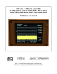
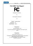
1
Installation Note
Agilent ESG and ESG-D Series Signal Generators
Add Option 1E5 Upgrade Kit
Kit Part Number E4400-60032
Part Number E4400-90111
Printed in USA
Supersedes: July 1998
September 2001
Notice.
The information contained in this document is subject to change without notice.
Agilent Technologies makes no warranty of any kind with regard to this material, including but not limited
to, the implied warranties of merchantability and fitness for a particular purpose. Agilent Technologies
shall not be liable for errors contained herein or for incidental or consequential damages in connection with
the furnishing, performance, or use of this material.
© Copyright Agilent Technologies Inc. 1997, 1998, 2001
All Rights Reserved. Reproduction, adaptation, or translation without prior written permission is
prohibited, except as allowed under the copyright laws.
1400 Fountaingrove Parkway, Santa Rosa, CA 95403-1799, USA
Option 1E5 Upgrade Kit
Product Affected: . . . . . . . . . . . . . . . . . . . . . . . .
ESG and ESG-D Series Signal Generators
Models Affected: . . . . . . . . . . . . . . . . . . . . . . . . .
E4400B/BU, E4400BK, E4420B/BU, E4421B/BU,
E4422B/BU, E4430B/BU, E4431B/BU, E4432B/BU,
E4433B/BU, and E4430BK
Serial Numbers: . . . . . . . . . . . . . . . . . . . . . . . . .
All
To Be Performed By: . . . . . . . . . . . . . . . . . . . . .
( X ) Agilent Technologies Service Center
( X ) Personnel Qualified by Agilent Technologies
( X ) Customer
Estimated Installation Time: . . . . . . . . . . . . . .
1.5 Hours
Estimated Verification Time: . . . . . . . . . . . . . .
4.0 Hours
Introduction
This kit contains the parts and instructions to replace the standard TCXO reference assembly with the
high stability OCXO timebase reference.
Installation Kit Parts List
Table 1
Installation Kit E4400-60032 Parts List
Item
Quantity
Description
Part Number
1
1
OCXO Reference Board, Option 1E5
2
1
Label, Option 1E5
3
1
ESG and ESG-D Service Support Software
E4400-10006
4
1
Installation Note
E4400-90111
E4400-60009
7120-1232
Tools Required
❏ T-10 TORX screwdriver
❏ T-15 TORX screwdriver
❏ T-8 TORX screwdriver
❏ Long nose pliers
Installation Note E4400-90111
3
Equipment Required
• 33120A Function Generator
• 3458A Digital Voltmeter
• 438A Power Meter
• 8482A Power Sensor
• 8491A/B Option 010 Attenuator
• 8491A/B Option 006 Attenuator
• 8902 Measuring Receiver
• 53131/32A Universal Counter
• 8563A Spectrum Analyzer
• 8663A Signal Generator
• 8904A Function Synthesizer
• MD/DMC-174 Mixer (Frequency 0.001 to 2.8 GHz)
• MD/MDC-164 Mixer (Frequency 0.5 to 9 GHz)
• HP Vectra personal Computer, with:
• CPU: 386 (or better)
• Clock: 33 MHz (or better)
• RAM: 8 Mb (or more)
• 3.5” Floppy Disk Drive
• 350 Mb (or more) Hard Drive
• 16-color VGA Monitor
• MS Windows 3.X (Microsoft Windows is a registered trademark of Microsoft Corp.)
• HP LaserJet 5L Printer (MS Windows supported)
• 82341C GPIB Interface Card (No substitution allowed)
Perform the Functionality Check
This procedure verifies that the signal generator powers up and that the internal instrument check
identifies no errors. The internal check evaluates the correctness of operation and returns an error
message if a problem is detected.
1. Turn power on to the signal generator by pressing the power switch. The green LED will light. Let
the instrument warm up for one hour.
2. Cycle the power to the signal generator. The green LED should again be lit and the instrument will
perform a check.
3. When the display is lit, check to see if the ERR annunciator is turned on.
4
Installation Note E4400-90111
4. If the ERR annunciator is turned on, review the error messages in the queue by pressing, Utility >
Error Info > View Next Error Message. The first error message in the queue will be shown in the text
area of the display. Refer to the service guide for information about the error message.
If there is more than one error message (each message will be designated as 1 of n), continue
pressing the View Next Error Message softkey until you have seen all of the messages.
5. When you have resolved all of the error messages, press Clear Error Queue(s) to delete the messages.
Then restart this procedure at step two.
NOTE
Once Option 1E5 is installed, ERROR 514, Reference Oven Cold will occur
whenever the signal generator is first connected to AC line power. The OVEN COLD
annunciator and the ERR annunciator will both turn on. The OVEN COLD
annunciator will automatically clear after approximately 5 minutes. The error
queue cannot be cleared, however, until the OVEN COLD annunciator has turned
off.
Installation Note E4400-90111
5
Installation Procedure
WARNING
Before you disassemble the instrument, turn the power switch off and
unplug the instrument. Failure to unplug the instrument can result in
personal injury.
CAUTION
Electrostatic discharge (ESD) can damage or destroy electronic components. All
work on electronic assemblies should be performed at a static-safe workstation.
Remove the Instrument Cover
1. Turn the power switch off and unplug the signal generator.
2. Remove the two strap handles (item 1 in Figure 1) from each side of the signal generator by
loosening the two screws (item 2 in Figure 1).
3. Remove the four bottom feet (item 3 in Figure 1).
4. Remove the rear four feet (item 4 in Figure 1) from the signal generator by removing the four screws
(item 5 in Figure 1) that secure them.
5. Slide the instrument cover (item 6 in Figure 1) off the back of the signal generator.
Figure 1
6
Removing the Instrument Cover
Installation Note E4400-90111
Remove the Right-Side Cover
1. Remove the four screws that attach the right-side cover to the instrument chassis.
2. Push down on the cover while sliding it toward the front of the instrument thereby unhooking its
tabs from the slots on the top of the chassis.
Remove the A11 TCXO Reference Assembly
1. Simultaneously lift the left and right extractors on the A11 assembly and remove the assembly from
the card cage slot. (Refer to Figure 2 for location of A11.)
Figure 2
A11 Location
Install the Option 1E5 A11 OCXO Reference Assembly
1. Slide the Option 1E5 A11 assembly into the A11 card cage slot.
2. Push down on both extractors until the assembly is seated in the slot.
Re-install the Right-Side Cover
1. Push down on the cover while sliding it toward the rear of the instrument. Hook the tabs into the
slots on the top of the chassis.
2. Replace the four screws that attach the right-side cover to the instrument chassis. Torque the
screws to 9 in-lbs.
Repeat the Functionality Check
1. Turn power on to the signal generator and let the instrument warm up for five minutes.
2. Preset the instrument by pressing the front panel Preset key.
3. Repeat the functionality check beginning at step 2.
Installation Note E4400-90111
7
Use the ESG/ESG-D Series Service Support Software to add
Option 1E5 Data to the Instrument
1. Load the ESG/ESG-D Series Service Support Software into the PC.
a. Insert the 82341C/C GPIB interface card into the PC.
NOTE
The GPIB interface card is not included in this installation upgrade kit. To order a
GPIB interface card contact you nearest Agilent Technologies sales office.
b. Load the HP SICL Libraries that came with the GPIB card onto the PC.
NOTE
The HP SICL Libraries must be installed and configured on the PC before the
ESG/ESG-D Service Support Software will run.
2. Connect the instrument to the GPIB interface card, using a GPIB cable. Turn the instrument on.
3. From the PC start menu, run the ESG/ESG-D Service Support Software. Follow these steps to add
Option 1E5 to the instrument:
a. Select Aglient Service Software for PC, click on the ESG/ESG-D Motherboard Utility sub menu.
b. Enter Falcon for the password (case sensitive).
c. With the ESG/ESG-D Service Motherboard Configuration Utility screen showing, press Query, to
view the instruments identity information.
d. Under Option Configuration select 1E5 High Stability Timebase.
e. Click download. The Option 1E5 data will be downloaded in the instrument.
NOTE
To avoid error messages the hardware for Option 1E5 must be installed in the
instrument prior to downloading the Option 1E5 data.
NOTE
The lastest ESG Calibration Guide, part number E4400-90325, may be used to
assist you. To obtain a copy of the calibration guide please contact your nearest
Agilent Technologies sales office.
Activate the New Option
1. Preset the instrument by pressing the front panel Preset key.
2. Press Utility > Instrument Adjustments > Hardware Options. Arrow down to Option 1E5, press
Select Item > Proceed with Reconfiguration.
3. Press Confirm Change. (The instrument will reboot to preset conditions.)
Perform the Automated Adjustments
To adjust the new Option 1E5 reference assembly, perform the following adjustments in the order
shown.
NOTE
The instrument must be turned on for 30 minutes.
NOTE
These adjustments are automated using the “ESG Series Support Software”. This
software is included in the signal generator documentation set as a part of the
calibration guide. To order an additional copy of the software, request part
number E4400-10006.
1. Internal Source Calibration
2. AM Audio Path Offset Calibration
8
Installation Note E4400-90111
3. Timebase DAC Calibration
4. FM Scale DAC Offset Calibration
5. FM Path Offset Calibration
6. FM In-band DAC Offset Calibration
7. FM Inserting Amplifier Offset Calibration
8. FM 1/2 Path Ratio Gain Calibration
9. Modulation Source Relative Gain Calibration
10. FM Relay Pot Adjustment
11. Wide BW PM Cal
12. DCFM Cal
13. FM Out of Band Cal
14. LF Output Cal
15. Burst Audio Put Cal (ESG-D only)
16. AM audio Path Gain Cal
Verify Instrument Performance
To verify the performance of the signal generator, complete the following performance tests.
NOTE
These performance tests are automated using the “ESG Series Support Software”.
1. AM Frequency Response
8. Internal FM Distortion
2. Burst Modulation On/Off Ratio (HP ESG-D only)
9. Nonharmonic Spurious Signals
3. DCFM Frequency Offset
10. Phase Modulation Accuracy
4. FM Frequency Response
11. Phase Modulation Distortion
5. Internal AM Accuracy
12. Phase Modulation Frequency Response
6. Internal AM Distortion
13. Residual FM
7. Internal FM Accuracy
14. Timebase Aging Rate
Installation Note E4400-90111
9
Replace the Instrument Cover
1. Turn off and unplug the instrument.
2. Re-install the instrument top cover with the 11 screws that secure it. Torque the screws to 9 in-lbs.
3. Replace the four rear feet and torque the screws to 21 in-lbs.
4. Replace the strap handles and torque the screws to 21 in-lbs.
Contacting Agilent Technologies
Table 3
Contacting Agilent
Online assistance: www.agilent.com/find/assist
United States
(tel) 1 800 452 4844
Latin America
(tel) (305) 269 7500
(fax) (305) 269 7599
Canada
(tel) 1 877 894 4414
(fax) (905) 282-6495
New Zealand
(tel) 0 800 738 378
(fax) (+64) 4 495 8950
Japan
(tel) (+81) 426 56 7832
(fax) (+81) 426 56 7840
Australia
(tel) 1 800 629 485
(fax) (+61) 3 9210
5947
Europe
(tel) (+31) 20 547
2323
(fax) (+31) 20 547
2390
Asia Call Center Numbers
Country
Phone Number
Fax Number
Singapore
1-800-375-8100
(65) 836-0252
Malaysia
1-800-828-848
1-800-801664
Philippines
(632) 8426802
1-800-16510170 (PLDT
Subscriber Only)
(632) 8426809
1-800-16510288 (PLDT
Subscriber Only)
Thailand
(088) 226-008 (outside
Bangkok)
(662) 661-3999 (within
Bangkok)
(66) 1-661-3714
Hong Kong
800-930-871
(852) 2506 9233
Taiwan
0800-047-866
(886) 2 25456723
People’s
Republic of
China
800-810-0189 (preferred)
10800-650-0021
10800-650-0121
India
1-600-11-2929
000-800-650-1101
10
Installation Note E4400-90111