1
Part Number:313433501
Shared Virtual Array
SVA Path
Version 3.1
HP-UX
User’s Guide
Proprietary Information Statement
The information in this document is confidential and proprietary to Storage Technology
Corporation and may be used only under the terms of the product license or nondisclosure agreement. The information in this document, including any associated software program, may not be
disclosed, disseminated, or distributed in any manner without the written consent of Storage
Technology Corporation.
Limitations on Warranties and Liability
This document neither extends nor creates warranties of any nature, expressed or implied. Storage
Technology Corporation cannot accept any responsibility for your use of the information in this
document or for your use of any associated software program. You are responsible for backing up
your data. You should be careful to ensure that your use of the information complies with all applicable laws, rules, and regulations of the jurisdictions in which it is used.
Warning: No part or portion of this document may be reproduced in any manner or in any form
without the written permission of Storage Technology Corporation.
Restricted Rights
Use, duplication, or disclosure by the U.S. Government is subject to restrictions as set forth in subparagraph (c)(1)(ii) of the Rights in Technical Data and Computer Software clause at DFARS
252.227–7013 or subparagraphs (c)(1) and (2) of the Commercial Computer Software—Restricted
Rights at 48 CFR 52.227–19, as applicable.
Trademarks
StorageTek is a registered trademark, and Shared Virtual Array and SVA are trademarks of Storage
Technology Corporation.
UNIX is a registered trademark of The Open Group.
Other terms and product names used herein may be trademarks of their respective owners.
First Edition (1.0) March 2001
This edition applies to Version 3.1 of the SVA Path for HP-UX product and to all subsequent modifications of that program until otherwise indicated in new editions or revision pages. If there are
changes in the program or improvements in the information about the program, this document will
be revised and reissued.
Comments concerning the contents of this manual should be directed to:
Storage Technology Corporation
Manager, Enterprise Disk Information Development
One StorageTek Drive
Louisville, CO 80028-2201
© Copyright Storage Technology Corporation 2001. All rights reserved.
© Copyright Dot Hill Systems Corp. 2001. All rights reserved.
Table of Contents
Who Should Read This Guide . . . . . . . . . . . . . . . . . . . . . . . . . . . . . . . . . . . . . . . . . . . . . . . . . . vii
Shared Virtual Array Documentation . . . . . . . . . . . . . . . . . . . . . . . . . . . . . . . . . . . . . . . . . . . . . vii
How to Obtain Software Documentation . . . . . . . . . . . . . . . . . . . . . . . . . . . . . . . . . . . . . . . vii
SVA Administrator for HP-UX Library . . . . . . . . . . . . . . . . . . . . . . . . . . . . . . . . . . . . . . . . viii
Related SVA Software Publications . . . . . . . . . . . . . . . . . . . . . . . . . . . . . . . . . . . . . . . . . . . viii
SVA Hardware Publications . . . . . . . . . . . . . . . . . . . . . . . . . . . . . . . . . . . . . . . . . . . . . . . . .
ix
Chapter 1. SVA Path Overview . . . . . . . . . . . . . . . . . . . . . . . . . . . . . . . . . . . . . . . . . . . . . . . . . . . .
1
Failover/Failback Data Paths . . . . . . . . . . . . . . . . . . . . . . . . . . . . . . . . . . . . . . . . . . . . . . . . . . . .
1
Load Balancing . . . . . . . . . . . . . . . . . . . . . . . . . . . . . . . . . . . . . . . . . . . . . . . . . . . . . . . . . . . . . .
1
Dynamic Allocation of Device Resources . . . . . . . . . . . . . . . . . . . . . . . . . . . . . . . . . . . . . . . . . .
2
How SVA Path Works . . . . . . . . . . . . . . . . . . . . . . . . . . . . . . . . . . . . . . . . . . . . . . . . . . . . . . . . .
2
Supported SVA Path Configurations . . . . . . . . . . . . . . . . . . . . . . . . . . . . . . . . . . . . . . . . . . . . . .
3
System Requirements . . . . . . . . . . . . . . . . . . . . . . . . . . . . . . . . . . . . . . . . . . . . . . . . . . . . . .
3
SAM Support . . . . . . . . . . . . . . . . . . . . . . . . . . . . . . . . . . . . . . . . . . . . . . . . . . . . . . . . . . . . .
3
Summary of SVA Path Benefits . . . . . . . . . . . . . . . . . . . . . . . . . . . . . . . . . . . . . . . . . . . . . . . . . .
4
Document Overview . . . . . . . . . . . . . . . . . . . . . . . . . . . . . . . . . . . . . . . . . . . . . . . . . . . . . . . . . .
4
Chapter 2. SVA Path Hardware Setup . . . . . . . . . . . . . . . . . . . . . . . . . . . . . . . . . . . . . . . . . . . . .
5
Fibre Addressing Concepts . . . . . . . . . . . . . . . . . . . . . . . . . . . . . . . . . . . . . . . . . . . . . . . . . . . . .
5
Host Bus Adapters/Initiators . . . . . . . . . . . . . . . . . . . . . . . . . . . . . . . . . . . . . . . . . . . . . . . . .
5
Domains in Fibre Channel Connection . . . . . . . . . . . . . . . . . . . . . . . . . . . . . . . . . . . . . . . . .
5
Domain Numbering . . . . . . . . . . . . . . . . . . . . . . . . . . . . . . . . . . . . . . . . . . . . . . . . . . . . . . . .
6
Domain Numbering with Fibre and
SVA Path . . . . . . . . . . . . . . . . . . . . . . . . . . . . . . . . . . . . . . . . . . . . . . . . . . . . . . . . . . . . . . . .
7
Configuration in a Mixed SCSI/Fibre Environment . . . . . . . . . . . . . . . . . . . . . . . . . . . . . . . . . .
8
Hardware Preparation . . . . . . . . . . . . . . . . . . . . . . . . . . . . . . . . . . . . . . . . . . . . . . . . . . . . . . . . .
9
Configuring an HP System to See New Devices. . . . . . . . . . . . . . . . . . . . . . . . . . . . . . . . . .
9
Table of Contents
iii
Chapter 3. SVA Path Operation . . . . . . . . . . . . . . . . . . . . . . . . . . . . . . . . . . . . . . . . . . . . . . . . . . .
11
The setsp Command . . . . . . . . . . . . . . . . . . . . . . . . . . . . . . . . . . . . . . . . . . . . . . . . . . . . . . . . . .
11
The spmon Command . . . . . . . . . . . . . . . . . . . . . . . . . . . . . . . . . . . . . . . . . . . . . . . . . . . . . . . . .
14
Configuring Load Balancing . . . . . . . . . . . . . . . . . . . . . . . . . . . . . . . . . . . . . . . . . . . . . . . .
14
How to Verify Load Balancing. . . . . . . . . . . . . . . . . . . . . . . . . . . . . . . . . . . . . . . . . . . . . . .
16
Adding FDevs to an Existing Lun . . . . . . . . . . . . . . . . . . . . . . . . . . . . . . . . . . . . . . . . . . . .
19
The sppath Command . . . . . . . . . . . . . . . . . . . . . . . . . . . . . . . . . . . . . . . . . . . . . . . . . . . . . . . . .
20
Display Options for sppath . . . . . . . . . . . . . . . . . . . . . . . . . . . . . . . . . . . . . . . . . . . . . . . . . .
21
Ignoring and Reclaiming Devices with sppath . . . . . . . . . . . . . . . . . . . . . . . . . . . . . . . . . . .
22
Understanding the setsp -a Screen . . . . . . . . . . . . . . . . . . . . . . . . . . . . . . . . . . . . . . . . . . . . . . .
23
Changing the Configuration . . . . . . . . . . . . . . . . . . . . . . . . . . . . . . . . . . . . . . . . . . . . . . . . . . . .
25
Specifying a Device for setsp . . . . . . . . . . . . . . . . . . . . . . . . . . . . . . . . . . . . . . . . . . . . . . . .
25
Assigning a New Primary Path . . . . . . . . . . . . . . . . . . . . . . . . . . . . . . . . . . . . . . . . . . . . . . .
26
Turning the Exclusion Setting Off and On . . . . . . . . . . . . . . . . . . . . . . . . . . . . . . . . . . . . . .
26
Redefining the Buffer Pointer Allocation . . . . . . . . . . . . . . . . . . . . . . . . . . . . . . . . . . . . . . .
27
Turning Load Balancing On and Off . . . . . . . . . . . . . . . . . . . . . . . . . . . . . . . . . . . . . . . . . .
27
Changing the Retry Count and Retry Delay . . . . . . . . . . . . . . . . . . . . . . . . . . . . . . . . . . . . .
27
Turning Failback Off and On . . . . . . . . . . . . . . . . . . . . . . . . . . . . . . . . . . . . . . . . . . . . . . . .
28
Dynamic Device Detection . . . . . . . . . . . . . . . . . . . . . . . . . . . . . . . . . . . . . . . . . . . . . . . . . . . . .
28
Chapter 4. SVA Path Installation . . . . . . . . . . . . . . . . . . . . . . . . . . . . . . . . . . . . . . . . . . . . . . . . . .
31
Installing SVA Path on HP-UX . . . . . . . . . . . . . . . . . . . . . . . . . . . . . . . . . . . . . . . . . . . . . . . . . .
31
iv
Installing SVA Path with SVA Administrator . . . . . . . . . . . . . . . . . . . . . . . . . . . . . . . . . . . . . . .
33
Uninstalling SVA Path . . . . . . . . . . . . . . . . . . . . . . . . . . . . . . . . . . . . . . . . . . . . . . . . . . . . . . . .
34
Installed Files . . . . . . . . . . . . . . . . . . . . . . . . . . . . . . . . . . . . . . . . . . . . . . . . . . . . . . . . . . . . . . .
35
SVA Path Device Naming on HP-UX . . . . . . . . . . . . . . . . . . . . . . . . . . . . . . . . . . . . . . . . . . . . .
37
How Device Filenames Are Chosen . . . . . . . . . . . . . . . . . . . . . . . . . . . . . . . . . . . . . . . . . . .
38
Devices without Redundant Paths to the Host . . . . . . . . . . . . . . . . . . . . . . . . . . . . . . . . . . .
40
Logical Volume Manager . . . . . . . . . . . . . . . . . . . . . . . . . . . . . . . . . . . . . . . . . . . . . . . . . . . . . .
40
Definitions of Common Terms . . . . . . . . . . . . . . . . . . . . . . . . . . . . . . . . . . . . . . . . . . . . . . .
41
Preparing the Volume Group . . . . . . . . . . . . . . . . . . . . . . . . . . . . . . . . . . . . . . . . . . . . . . . .
42
Creating the Physical Volume . . . . . . . . . . . . . . . . . . . . . . . . . . . . . . . . . . . . . . . . . . . . . . .
43
Creating the Volume Group . . . . . . . . . . . . . . . . . . . . . . . . . . . . . . . . . . . . . . . . . . . . . . . . .
43
Creating Logical Volumes . . . . . . . . . . . . . . . . . . . . . . . . . . . . . . . . . . . . . . . . . . . . . . . . . .
44
Reconfiguration for Existing Applications . . . . . . . . . . . . . . . . . . . . . . . . . . . . . . . . . . . . . .
46
Reconfiguration for Existing Logical Volumes . . . . . . . . . . . . . . . . . . . . . . . . . . . . . . . . . .
46
SVA Path User’s Guide
Chapter 5. Diagnosing Errors. . . . . . . . . . . . . . . . . . . . . . . . . . . . . . . . . . . . . . . . . . . . . . . . . . . . . . 51
Comparing setsp -a with System Events . . . . . . . . . . . . . . . . . . . . . . . . . . . . . . . . . . . . . . . . . . . 51
Cable Failure Errors . . . . . . . . . . . . . . . . . . . . . . . . . . . . . . . . . . . . . . . . . . . . . . . . . . . . . . . . . . . 52
Failover Error Reporting . . . . . . . . . . . . . . . . . . . . . . . . . . . . . . . . . . . . . . . . . . . . . . . . . . . . . . . 53
Recovering from a Failure . . . . . . . . . . . . . . . . . . . . . . . . . . . . . . . . . . . . . . . . . . . . . . . . . . . . . . 54
Table of Contents
v
vi
SVA Path User’s Guide
Preface
This guide describes how to use the SVA Path Intelligent Data
Path Management software. SVA Path provides improved
performance and data accessibility for the StorageTek Shared
Virtual Array (SVA).
Who Should Read This Guide
This guide is for data administrators, capacity planners,
performance specialists, and system administrators. This guide
assumes that you are familiar with Shared Virtual Array
operations and HP-UX system administration.
Shared Virtual Array Documentation
This section lists software and hardware documentation for the
Shared Virtual Array products.
How to Obtain
Software
Documentation
All of the Shared Virtual Array software publications are available
from the following sources:
•
On the SVA Software Publications CD-ROM (part number
3112953nn). To order a copy, contact StorageTek
Publication Sales and Service at 800-436-5554 or send a fax
to 303-661-7367.
Preface
vii
•
Online (for viewing and printing), at the StorageTek
Customer Resource Center (CRC) website at:
www.support.storagetek.com. Click on Software and go to
the Shared Virtual Array Software list.
Note: Access to the CRC site requires a password. To obtain
a password, call StorageTek Customer Support at
800-678-4430.
SVA Administrator
for HP-UX Library
Related SVA
Software
Publications
•
Shared Virtual Array Administrator for HP-UX
Command Quick Reference
•
Shared Virtual Array Administrator for HP-UX
Installation Guide
•
Shared Virtual Array Administrator for HP-UX
Messages
•
Shared Virtual Array Administrator for HP-UX
Quick Start Guide
•
Shared Virtual Array Administrator for HP-UX
User’s Guide
For SVA SnapShot for HP-UX:
•
Shared Virtual Array SnapShot for HP-UX
User’s Guide
•
Shared Virtual Array SnapShot for HP-UX
Quick Start Guide
For SVA Console for Windows NT (SVAC):
•
Shared Virtual Array Console for Windows NT
Quick Start Guide
For any StorageTek software:
•
viii
SVA Path User’s Guide
Requesting Help from Software Support
SVA Hardware
Publications
Shared Virtual Array hardware publications are available from the
following sources:
•
On the SVA Hardware Publications CD-ROM (part number
3118447nn). To order a copy, contact StorageTek
Publication Sales and Service at 800-436-5554 or send a fax
to 303-661-7367.
•
Online (for viewing and printing), at the StorageTek
Customer Resource Center (CRC) website at:
www.support.storagetek.com. Click on Disk Subsystems.
Note: Access to the CRC site requires a password. To obtain
a password, call StorageTek Customer Support at
800-678-4430.
The 9500 SVA library consists of:
•
9500 Shared Virtual Array
Introduction
•
9500 Shared Virtual Array
Operation and Recovery
•
9500 Shared Virtual Array
Physical Planning
•
9500 Shared Virtual Array
Planning, Implementation, and Usage
•
9500 Shared Virtual Array
Reference
•
9500 Shared Virtual Array
System Assurance
Preface
ix
x
SVA Path User’s Guide
Chapter 1. SVA Path Overview
This chapter provides an overview of SVA Path Intelligent Data
Path Management software and its features.
SVA Path offers a new level of data accessibility and improved
performance for the SVA 9500. It eliminates the point of failure
represented by a single input/output (I/O) path between servers
and storage systems and permits I/O to be distributed across
multiple paths.
Failover/Failback Data Paths
By providing alternate I/O paths from the server to the SVA, SVA
Path provides uninterrupted access to mission-critical data. This
substantially insulates server applications from I/O path failures.
In the event of a failed host bus adapter (HBA), interface cable, or
channel I/O card within the SVA, SVA Path automatically reroutes
I/O traffic to an alternate data path. Failover is essentially
transparent, ensuring continuous access to data stored on the SVA.
When configured in the recommended failback mode, SVA Path
automatically restores the primary data path and system
redundancy once the defective component is replaced.
Load Balancing
SVA Path supports up to 32 data paths between a host and any
SVA logical device. Since only two data paths are required for
path failover capability, multiple data paths can be used to
improve performance in one of three ways:
Chapter 1.
SVA Path Overview
1
1.
by allowing SVA Path to uniformly distribute primary paths
among all available I/O paths. This is the default behavior of
SVA Path.
2.
by manually assigning I/O traffic for a logical drive to a
particular path. The administrator with an understanding of
the I/O load patterns of his or her applications can optimize
performance through an intelligent choice of paths.
3.
by enabling automatic load balancing. In this mode of
operation SVA Path monitors the load on each path and
sends I/O requests through the path with the lightest load.
Dynamic Allocation of Device Resources
In SVA configurations with multiple servers attached to the same
storage device, SVA Path allows the system administrator to
assign a logical drive to one server and prevent the other servers in
the SVA from accessing that same logical drive.
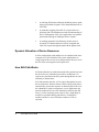
How SVA Path Works
SVA Path’s filter driver resides between the file system drivers and
the device drivers, within the layered driver architecture. I/O
requests are passed from the file system through the drivers and
ultimately to the hardware.
SVA Path monitors the flow of I/O requests through the layered
driver architecture. When it detects a failure along an I/O path, it
automatically reroutes the request to an alternate path. Failover to
the redundant I/O path is transparent to server applications and
permits continuous access to the information stored on the disk
array(s). To the operating system, there is only a slight delay in
normal I/O operations during path failover; existing drive
numbers and device access functions continue to work as
expected.
2
SVA Path User’s Guide
Supported SVA Path Configurations
SVA Path supports single server configurations.
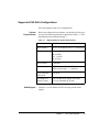
System
Requirements
Before proceeding to the next chapter, you should verify that your
site meets the following minimum requirements (Table 1-1, “SVA
Path Minimum System Requirements”).
Table 1-1
SAM Support
SVA Path Minimum System Requirements
Host hardware:
All 9000 series computers
Host software:
HP-UX 10.20 and HP-UX 11.x, 32 and 64 bit
HBA
10.2, 11.0 HSC
HP A3404B
10.2, 11.0 PCI
HP A3740A
Host software
X Windows
Host disk space:
5 MB free space in the root filesystem and 1
MB free space in the /var directory.
SVA Subsystem
Microcode:
K05.04.08
Extended SCSI
Attach Feature:
One Extended SCSI Attach (microcode
S358) per redundant SCSI path
Version 3.1 of SVA Path for HP-UX does not provide SAM
support.
Chapter 1.
SVA Path Overview
3
Summary of SVA Path Benefits
•
Increases potential subsystem throughput by directing I/O
through multiple host adapters and SVA channels. Logical
drives can be assigned to host bus adapters, manually
balancing the I/O load across paths.
•
Provides continuous access to mission-critical data by
insulating server applications from I/O path failures.
•
Installs easily and is transparent to server applications.
•
Allows you to limit access to devices in a multi-initiator
(SVA) environment using LUN (logical unit number)
exclusion.
Document Overview
This manual describes how to install and configure SVA Path on
systems running the HP-UX operating system.
•
Chapter 2 describes configuring your hardware in
preparation for installing SVA Path.
•
Chapter 3 explains configuring and operation SVA Path.
•
Chapter 4 contains the instructions for installing SVA Path.
•
Chapter 5 offers assistance in diagnosing error messages.
Note that user documentation for products used with SVA Path,
including HP-UX documentation, is referenced throughout this
manual. Have your hardware and operating system manuals
available for quick reference.
4
SVA Path User’s Guide
Chapter 2. SVA Path Hardware Setup
Fibre Addressing Concepts
Host Bus
Adapters/Initiators
The terms “host bus adapter” and “initiator” mean essentially the
same thing. Typically, the HBA is a card within the host that, in its
role as initiator, issues commands on the Fibre channel.
Domains in Fibre
Channel Connection
StorageTek uses the concept of “domains” to allow open systems
hosts access to blocks of logical devices (the domains) within an
SVA. A domain is an additional layer of device addressing, but one
that is manually configured by the CSE in the SVA. This layer of
addressing divides the SVA into “domains of access.” There can
be up to 16 (0–15) domains per SVA, with each domain having one
target with 255 LUNs. There is a limit of 1024 total devices
available within an SVA.1
Each open systems host initiator is connected with Fibre cables to
a controller card port, giving it access to the devices that have been
configured within its domain. (An open systems host cannot see
devices in domains other than the one to which it is attached.)
Full SVA Path functionality requires that redundant initiators can
access the SVA over redundant data paths.
1. Using all allowed domains, targets, and LUNs, there are more than 1024 logical devices, but
the SVA has a limit of 1024 logical devices.
Chapter 2.
SVA Path Hardware Setup
5
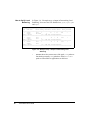
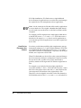
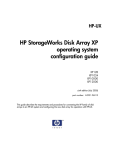
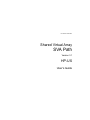
Figure 2-1 shows two data paths connecting the open systems
platform to the attached SVA using Fibre cables.
Shared Virtual Array
Open
Systems
Platform
ICF Cards
Fibre Cable
Fibre Cable
Domain 0
Domain 1
Domain 2
Domain 3
Fibre Cable
Fibre Cable
ICF Cards
Figure 2-1 Fibre Paths from the Host to the SVA
Note: In the above figure, a domain can represent up to 255
logical devices (1 Target × 255 LUNs = 255 Logical
Devices). There is a limit of 1024 logical devices with an
SVA.
Domain Numbering
Using Fibre connection, the domain number is configured at the
SVA operator panel by the StorageTek Customer Service
Engineer.
The domain number is never seen by the open systems host; from
its point of view, just a target and logical unit number are involved
in an I/O operation.
6
SVA Path User’s Guide
Domain Numbering
with Fibre and
SVA Path
It is not normally advisable to have more than one path from a
single host set to the same domain number to a given SVA (in case
two hosts attempt to share the same LUN and so corrupt the data
stored on it). SVA Path requires exactly this configuration for
failover to work.
SVA Path manages multiple paths from a single host, using
identical domain numbers.
Chapter 2.
SVA Path Hardware Setup
7
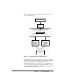
Configuration in a Mixed SCSI/Fibre Environment
Failover can only be accomplished from one SCSI interface to
another, or from one Fibre interface to another.
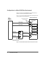
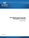
Figure 2-2 shows SCSI and Fibre data paths connecting the open
systems platform to the attached SVA.
Shared Virtual Array
Open
Systems
Platform
Fibre Card domain settings
(must be the same)
ICF Cards
Fibre Cable
1
Fibre Cable
1
Domain 0
Domain 1
Domain 2
SCSI Bus
SCSI Bus
0
ESCON Cable
XSA
Feature
ESCON Cable
Domain 3
ICE Cards
0
Domain thumbwheel switch
settings (must be the same)
Figure 2-2 Mixed SCSI and Fibre Paths from the Host to the SVA
8
SVA Path User’s Guide
Hardware Preparation
Configuring an HP
System to See New
Devices
Perform the following steps on the HP host:
Note: If any of the following steps do not produce the
expected result, refer to your HP-UX system administrator
documentation for instructions on setting up the host
platform correctly.
1.
For Fibre channel connection, contact your Custome Service
Engineer to set domain addresses in the SVA 9500. For
SCSI, manually set the domain addresses on the SVA’s
XSAs to the required configuration and reboot the XSAs.
2.
Log in as root.
3.
Open a console or terminal window.
4.
Run ioscan and verify that the new storage resource is
recognized by the system:
# ioscan -fn
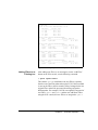
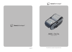
5.
Each of the three disk devices in our example is seen twice,
once on the first controller (c1) and again on the second
controller (c2).
Verify that all of the new device(s) you have defined are
included in the display. They are identified with a type of
STK-9200-nnnn.
Write down the first six characters (the controller, target, and
device numbers) of the new device(s). This information
looks something like:
c1t0d0
Chapter 2.
SVA Path Hardware Setup
9
Class
I
H/W Path
Driver S/W State
H/W Type
Description
================================================================================
disk
0
0/0/1/1.2.0
sdisk
CLAIMED
/dev/dsk/c1t2d0
disk
1
0/0/2/0.2.0
sdisk
CLAIMED
/dev/dsk/c2t2d0
disk
2
0/0/2/1.2.0
sdisk
CLAIMED
/dev/dsk/c3t2d0
disk
3
0/6/0/0.0.0
disk
4
0/6/0/0.1.0
sdisk
CLAIMED
/dev/dsk/c6t0d0
sdisk
CLAIMED
/dev/dsk/c6t1d0
disk
5
0/6/0/0.2.0
disk
6
0/6/0/0.3.0
sdisk
CLAIMED
/dev/dsk/c6t2d0
sdisk
CLAIMED
DEVICE
SEAGATE ST39103LC
/dev/rdsk/c1t2d0
DEVICE
SEAGATE ST39103LC
/dev/rdsk/c2t2d0
DEVICE
HP
DVD-ROM 6x/32x
/dev/rdsk/c3t2d0
DEVICE
STK
9500
/dev/rdsk/c6t0d0
DEVICE
STK
9500
/dev/rdsk/c6t1d0
DEVICE
STK
9500
/dev/rdsk/c6t2d0
DEVICE
STK
9500
Figure 2-3 Example format Output for a Dual -Path System
10
SVA Path User’s Guide
Chapter 3. SVA Path Operation
This chapter describes SVA Path commands and configuration
options.
There are three basic commands in SVA Path
•
setsp is used to examine and configure the system’s
operating parameters, and as such is the command most
often invoked by the user.
•
spmon monitors path states and implements load balancing.
•
sppath identifies devices to be placed under SVA Path's
control.
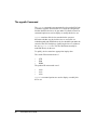
The setsp Command
The setsp command is used for most configuration tasks.
Table 3-1, “setsp Command Options”, on the next page gives a
brief explanation of setsp command options. Those used to
configure SVA Path device parameters are covered in some detail
in “Changing the Configuration”, beginning on page 25. In these
cases, the pages containing more detailed explanations of
command options are noted parenthetically.
The output of setsp -a is also used in conjunction with the event
listings in /var/adm/syslog/syslog.log to determine the
nature and physical location of failures. This is covered in
“Diagnosing Errors” starting on page 51.
Chapter 3.
SVA Path Operation
11
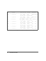
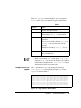
Command options that take arguments (shown in braces after the
command) require an argument and should not be run without one.
Table 3-1
Option
setsp Command Options
Effect
-a
show current device configuration and state
-b{0|1}
set load balancing for a logical drive. (pages
24 and 27).
-b0 disables load balancing for the device;
-b1 enables it
Must be used with -l
-d<n>
set a retry delay of n for a logical drive,
where n is the interval between retries in
milliseconds (page 24 and 27)
-e{0|1}
set exclusion for a logical drive (pages 24
and 26).
-e0 includes the device;
-e1 excludes it;
excluded devices are not accessible by user
applications;
devices are excluded by default
Must be used with -l
-f{0|1}
set failback for a logical drive.
-f0 disables failback for the device;
-f1 enables it (pages 25 and 28)
Must be used with -l
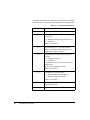
12
SVA Path User’s Guide
-g
generate configuration files after an sppath
command (Page 21)
-i
show contents of driver configuration files
Table 3-1
setsp Command Options
Option
Effect
-L <parameter>
show current device configuration according
to condition(s) defined by setsp command
option parameter(s) (e.g., setsp -L -e1
lists all excluded devices; setsp -L -b0
-f1 lists all devices that have load balancing
disabled and failback enabled);
acceptable parameters are: -l, -e, -p, -b, r, -d, and -f
-l{<n>|all}
specify a logical drive for the command,
where;
n is the drive’s spd number ;
all specifies all devices (page 25)
-N
runs a command to change the configuration
files without affecting the running system
(changes will take effect at the next boot)
-n<n>
allocate n buffer pointers for a logical drive,
where n should be a number approximately
equal to the device’s maximum queue depth.
(pages 24 and 27)
Must be used with -l.
-p<n>
select primary path n.
Must be used with -l.
-r<n>
set a retry count of n for a logical drive,
where n is the number of times a command
will be retried (pages 24 and 27)
-S
start the spd driver
-T
terminate the spd driver
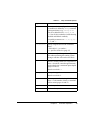
Chapter 3.
SVA Path Operation
13
Table 3-1
Option
-u{0|1|2}
setsp Command Options
Effect
show devices by their configuration status:
-u0 shows all available devices;
-u1 shows configured disks;
-u2 shows unconfigured disks
-v
runs a command in verbose mode
The spmon Command
The spmon command is primarily associated with load monitoring
and balancing of SVA Path functional devices (FDevs). FDev is a
logical disk as viewed by the host operating system, the
applications and the users. An Fdev can emulate one of a variety
of SCSI and count-key-data (CKD) disk devices.
Note: For optimum performance when striping data across
multiple LUNs, disable load balancing on the devices being
striped using the setsp -b0 option.
Configuring Load
Balancing
Load balancing is enabled or disabled using setsp -l all -b0
(disable) or setsp -l all -b1 (enable) commands, with the
default setting being load balancing is enabled. Parameters for
load balancing are stored in the configuration file
/etc/spmon.conf. This file is read automatically after each
modification at the end of the expiration of the last measurement
interval.
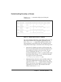
Following is a listing of available parameters in
/etc/spmon.conf:
•
balance-threshold percentage
This parameter is used to specify the maximum difference in
load on the high and low paths that is permitted before the
paths will be considered imbalanced. The load balancing
14
SVA Path User’s Guide
equation must be less than the percentage value of
balance-threshold to be considered balanced.
•
reassignment-threshold percentage
This parameter determines whether or not a reassignment
will be considered worthwhile.
•
measurement-interval time
This parameter accepts an positive integer value with a
suffix of "s" (seconds), "m" (minutes), or "h" (hours). A
reasonable minimum value will be based on the CPU load
presented to the system by the algorithm and the maximum
value is based on the amount of time that can pass before the
driver's internal counters overflow.
•
reassignment-limit number
This parameter specifies the maximum number of devices
that should be moved in one pass of the algorithm. The
default value is equal to or one half of the FDevs. If the path
group includes one or more multi-FDev LUNs, each FDev is
considered a separate device.
•
read-overhead µs-per-cmd µs-per-sector
This parameter is used to specify how bus connect time
overhead is estimated for read commands. The first value
specifies the number of microseconds estimated for read
command overhead, while the second is an estimate of
connect time required for each 512 bytes of data requested.
For each read operation, the sum of the command overhead
and the product of the transfer length and the per-sector
overhead is added to a counter that is used to estimate overall
bus utilization on a per-FDev and per-channel basis.
•
write-overhead µs-per-cmd µs-per-sector
This parameter is analogous to the read-overhead statement.
Sample values for these two statements are:
read-overhead 1000 120
write-overhead 1000 160
Chapter 3.
SVA Path Operation
15
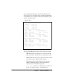
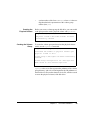
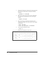
How to Verify Load
Balancing
In Figure 3-4, “Example setsp -a Output in Determining Load
Balancing”, there are four SVA Path devices; spd0, spd1, spd2
and spd3.
# setsp -a
===============================================================================
spd
Path/disk
Status Primary Exclude Buf Balance RtrCnt RtrDly FailBack
===============================================================================
0
c0t1d0
Good
X
32
1
20
3000
1
c3t0d0
Excluded
X
spd0 = c83t0d0
ID = "STK 9500 0000000010390000"
===============================================================================
1
c0t1d1
Good
32
1
20
3000
1
c3t0d1
Good
X
spd1 = c83t0d1
ID = "STK 9500 0000000010390001"
===============================================================================
2
c0t1d2
Good
X
32
1
20
3000
1
c3t0d2
Good
spd2 = c83t0d2
ID = "STK 9500 0000000010390002"
===============================================================================
Figure 3-4 Example setsp -a Output in Determining Load
Balancing
•
16
SVA Path User’s Guide
Status shows the current state of the path. Good paths are
functioning normally. Bad paths have failed. Excluded
paths are unavailable to applications on this host.
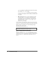
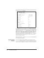
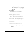
In our example, the following command will show that each
device in Figure 3-4, “Example setsp -a Output in Determining
Load Balancing” is accessible via four paths, using HBAs "glm3",
"glm4", “lpfc0” and “lpfc1”:
# spmon show
# spmon show
Total I/O load across monitored HBAs = 103.2s
HBA Device
I/O Load %load
-----------------------------c1 glm3
40.1s 38.8%
c2 glm4
20.8s 20.2%
c4 lpfc0
21.2s 20.6%
c5 lpfc1
21.1s 20.5%
Device c6t0d0 [STK 9500 0000000010850000]
FDev
Path
I/O Load
HBA Load
---------------------------------------------------------spd0:0
0/glm3/sd66
9.9s
40.1s 24.8%
Device c6t0d1 [STK 9500 0000000010850001]
FDev
Path
I/O Load
HBA Load
---------------------------------------------------------spd1:0
0/glm3/sd67
10.1s
40.1s 25.1%
spd1:1
3/lpfc1/sd190
21.2s
21.1s 100.0%
Device c6t0d2 [STK 9500 0000000010850002]
FDev
Path
I/O Load
HBA Load
---------------------------------------------------------spd2:0
0/glm3/sd68
9.9s
40.1s 24.7%
spd2:1
1/glm4/sd90
20.9s
20.8s 100.0%
spd2:2
2/lpfc0/sd147
21.2s
21.2s 100.0%
Device c6t0d3 [STK 9500 0000000010850222]
FDev
Path
I/O Load
HBA Load
---------------------------------------------------------spd3:0
0/glm3/sd69
10.0s
40.1s 24.9%
Figure 3-5 Example spmon show Output
The column headings describe the various fields on the screen:
•
FDev identifies the SVA Path device and the zero-based
index of the FDev within the device, separated by a colon.
•
Path identifies the current path assigned to the FDev and the
name of the host bus adapter used by that path.
•
I/O Load estimates channel utilization time during the
current measurement interval. The I/O Load may be
expressed as one of the following formats:
milliseconds (with an "ms" suffix) if it is less than one
second. For example, 350ms = 350 milliseconds
Chapter 3.
SVA Path Operation
17
seconds (with an "s" suffix) if it is less than 300 seconds.
For example, 18.1s = 28.1 seconds
hours:minutes:seconds (hh:mm:ss) if it is more than
59 minutes. For example, 0:12:42 = 0 hours, 12 minutes, and
42 seconds.
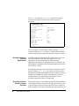
•
HBA Load identifies the I/O load contributed by traffic
to/from this FDev as a percentage of all I/O though the
current HBA used to access this FDev. The figure in the
right-hand column is a ratio I/O Load / HBA Load,
expressed as a percentage.
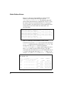
In this example, all four paths have about the same load on them
except for c1, which has nearly double the load of the other paths.
Shortly after this command was run, the following message
appeared in the system log file
/var/adm/syslog/syslog.log:
spmon daemon: moving spd2:0 from glm3 to lpfc1
spmon daemon: moving spd3:0 from glm3 to glm4
Figure 3-6 Example Output of spmon Daemon
When the command, spmon show, is run again (Page 19), the
output shows the load is redistributed among the four paths and the
maximum load on c1 is significantly reduced from 38.8% to
32.5%:
18
SVA Path User’s Guide
# spmon show
Total I/O load across monitored HBAs = 105.1s
HBA Device
I/O Load %load
-----------------------------c1 glm3
34.1s 32.5%
c2 glm4
31.3s 29.8%
c4 lpfc0
19.1s 18.1%
c5 lpfc1
20.6s 19.6%
Device c6t0d0 [STK 9500 0000000010850000]
FDev
Path
I/O Load
HBA Load
---------------------------------------------------------spd0:0
0/glm3/sd66
16.9s
34.1s 49.5%
Device c6t0d1 [STK 9500 0000000010850001]
FDev
Path
I/O Load
HBA Load
---------------------------------------------------------spd1:0
0/glm3/sd67
17.3s
34.1s 50.5%
spd1:1
3/lpfc1/sd190
10.2s
20.6s 49.6%
Device c6t0d2 [STK 9500 0000000010850002]
FDev
Path
I/O Load
HBA Load
---------------------------------------------------------spd2:0
3/lpfc1/sd191
10.4s
20.6s 50.4%
spd2:1
1/glm4/sd90
15.4s
31.3s 49.3%
spd2:2
2/lpfc0/sd147
19.1s
19.1s 100.0%
Device c6t0d3 [STK 9500 0000000010850222]
FDev
Path
I/O Load
HBA Load
---------------------------------------------------------spd3:0
1/glm4/sd91
15.9s
31.3s 50.7%
Figure 3-7 Example spmon show Output, Next Interval
Adding FDevs to an
Existing Lun
After adding new FDevs to an existing lun via the “Add FDev”
button on the SVA console, run the following command:
# spmon update-fdevs
This enables spmon to load balance the new FDevs separately
from the rest of the FDevs that make up the LUN. If this command
is not run, the FDevs will be treated as if they belonged to the last
original FDev and will be prevented from being assigned to
different paths. For example, if a LUN was originally composed of
two FDevs spd0:0 and spd0:1 and the user adds three FDevs
using the SVA console, the new FDevs are assigned to spd0:1.
Chapter 3.
SVA Path Operation
19
The sppath Command
The sppath command is run automatically at boot after SVA Path
is installed. sppath’s main function is to create the configuration
file that identifies devices to be put under SVA Path’s control. Its
command options are used to display or modify this device set.
sppath examines disk devices attached to the system to
determine whether any physical devices are accessible via
redundant paths and whether those devices should be put under the
control of the SVA Path driver. Qualifying devices are written to
the /etc/sppath.conf file. This file should not normally be
modified directly by the user.
To qualify, devices must have appropriate inquiry data.
The vendor ID must match one of:
•
STK
•
IBM
•
RSBA
The product ID must match one of:
•
•
•
9200
9393
9500
sppath’s command options are used to display or modify this
device set.
20
SVA Path User’s Guide
Table 3-2, “sppath Command Options” gives a synopsis of
sppath options. They are explained in greater detail below.
Table 3-2
Option
sppath Command
Options
Effect
-d
display debug information
-D
clear the list of ignored devices. Should be
followed by setsp -g (see note below)
-I{cXtYdZ}
ignore the device or group of devices
specified;
devices are specified in the form cX, cXtY, or
cXtYdZ. all devices that match will be
ignored;
Should be followed by setsp -g (see note
below)
-v
display the contents of /etc/sppath.conf
after writing the file
Note: After running sppath with options -I or -D, you
must run setsp -g in order for the changes to be reflected
in SVA Path’s configuration file /etc/spd.conf. Changes
will take effect at the next system reboot.
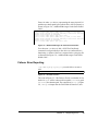
Display Options for
sppath
The -v option causes sppath to display the contents of
/etc/sppath.conf after updating it (Figure 3-8, “Using
sppath in Verbose Mode”).
# sppath -v
LUN=0 c5t0d0
LUN=0 c6t0d0
LUN=1 c5t0d1
LUN=1 c6t0d1
LUN=2 c1t0d0
LUN=3 c1t0d5
LUN=4 c1t1d5
LUN=5 c2t0d6
LUN=6 c2t1d6
dev=32,3840 type=2 SANID="STK 9500 000000001038000E"
dev=32,4800 type=2 SANID="STK 9500 000000001038000E"
dev=32,3848 type=2 SANID="STK 9500 000000001038000F"
dev=32,4808 type=2 SANID="STK 9500 000000001038000F"
dev=32,240 type=2 SANID="STK 9500 000000001038000C"
dev=32,2192 type=2 SANID="STK 9500 000000001038021C"
dev=32,2248 type=2 SANID="STK 9500 000000001038021D"
dev=32,3040 type=2 SANID="STK 9500 00000000103802F4"
dev=32,3096 type=2 SANID="STK 9500 00000000103802F5"
Figure 3-8 Using sppath in Verbose Mode
Chapter 3.
SVA Path Operation
21
The -d option displays inquiry data in raw format and is generally
used only for debugging.
Ignoring and
Reclaiming Devices
with sppath
The -I option accepts symbolic device names corresponding to
controllers or specific disks and omits them from
/etc/sppath.conf.
This prevents them from being put under SVA Path’s control.
If a device is to be ignored, all of its paths should be specified with
-I options. Multiple devices can be specified in a single sppath
command, but each device specified must be preceded by -I.
Once specified, the ignored device is remembered in
/etc/sppath.conf and will be ignored until the list of ignored
devices is cleared with setsp using the -D option. Ignored devices
will be seen as UNKNOWN by setsp -a. The ignored devices will
behave like standard disk drives not under the control of SVA
Path.
Run the following commands to ignore a device:
# setsp -T -l<spdX>
# sppath -I
# setsp -g
Alternately, you can also run sppath -I, followed by a reboot of
the host, in order for the operating system to recognize the ignored
device.
Note: The sppath -I (ignore) command should not be
confused with the setsp -e (exclude) command. The
former removes the device completely from SVA Path's
control, treating it exactly as though it is incompatible with
SVA Path and could not be recognized and claimed. The
setsp -e command is intended chiefly for multiple host
configurations and prevents particular logical devices from
being accessed by a host.
The -D option clears the entire list of ignored devices, allowing
any eligible device to be placed under SVA Path’s control upon the
next reconfiguration reboot.
22
SVA Path User’s Guide
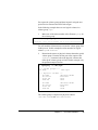
Understanding the setsp -a Screen
Use the setsp -a command to display the default path
configurations.
# setsp -a
===============================================================================
spd
Path/disk
Status Primary Exclude Buf Balance RtrCnt RtrDly FailBack
===============================================================================
0
c0t1d0
Good
X
X
32
1
20
3000
1
c3t0d0
Good
X
spd0 = c83t0d0
ID = "STK 9500 0000000010390000"
===============================================================================
1
c0t1d1
Good
X
32
1
20
3000
1
c3t0d1
Good
X
X
spd1 = c83t0d1
ID = "STK 9500 0000000010390001"
===============================================================================
2
c0t1d2
Good
X
X
32
1
20
3000
1
c3t0d2
Good
X
spd2 = c83t0d2
ID = "STK 9500 0000000010390002"
===============================================================================
Figure 3-1 Sample Output of setsp -a Command
The column headings identify the various fields on this screen, the
last seven of which are user-configurable parameters for the
device. The setsp -a output fields (with their default values,
when applicable) are described below. The commands used to
change the default settings are described in the following section.
•
spd is the SVA Path driver number, an ID assigned to the
device by SVA Path and the name of the spd special device
file created by SVA Path to access the storage. The spd
device is displayed in the form spdN = cXtYdZ, and
provides the spd number (N in the spdN field) and the virtual
device name (in the format cXtYdZ). This device number
also appears in errors reported in the
/var/adm/syslog/syslog.log file.
•
Path/disk shows the device names and disk numbers for
each of the redundant physical paths to the device. Their
appearance in the setsp -a output facilitates interpreting
these events in terms of the spd device names by which
applications access devices. This field shows the disk
number in the form of cXtYdZ.
Chapter 3.
SVA Path Operation
23
•
Status shows the current state of the path. Good paths are
functioning normally. Bad paths have failed.
•
Primary shows which of the physical I/O paths connecting
the device to the host’s host bus adapters (or controllers) is
defined as primary (marked by an X). Initially, primary path
assignments are distributed evenly among the available
paths. Figure 3-1, “Sample Output of setsp -a
Command” shows this as an alternating pattern in a dualpath configuration: spd0 has a primary path to controller 7,
spd1 uses its path to controller 8 as primary, and spd2
alternates back to controller 7. The device’s duplicate path(s)
are not used unless the primary path fails or the load
balancing option is selected for that device.
•
Exclude indicates the exclusion setting, which is used to
keep particular servers from seeing particular logical drives.
As a safety measure, SVA Path excludes all devices from
host access by default, giving them an exclusion setting of 1.
Excluded devices are marked by an X in this column.
•
Buf is the number of buffer pointers (or buffer structures)
pre-allocated for each logical device. For peak performance,
Buf should be approximately equal to the maximum useful
queue depth of the logical unit. Values between 1 and 100 are
permitted. The default value is 32.
•
Balance indicates whether dynamic load balancing is
enabled for the device. When load balancing is enabled,
SVA Path tracks the volume of I/O on each path and
automatically sends I/O requests to the path with the lightest
I/O load. 1 means load balancing enabled. 0 means load
balancing not enabled.
•
RtrCnt is the number of times a failed I/O will be retried on
the primary path after it has tried unsuccessfully to use its
alternate path(s) and returned again to the primary. When the
specified number of retries have failed, the I/O fails. The
default value is 20. The highest value allowed is 100.
•
RtrDly is the time interval, in milliseconds, between the
retry attempts described in the preceding parameter. The
24
SVA Path User’s Guide
default value is 3000 ms. This value can not be set above
100,000 ms (100s).
•
FailBack indicates whether failback is enabled for the
logical device. When failback is enabled (the default setting
of 1), SVA Path will keep testing a path that has failed and
return it to service (as the primary path or in sequential load
balancing) as soon as the path has been restored.
If the default configuration is satisfactory, no reconfiguration of
SVA Path is necessary.
In addition to the information defined by the setsp -a output's
column headings, the last part of the last line for each device (ID=)
shows the physical device's unique identifier, which is derived
from the device's inquiry data.
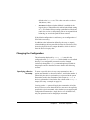
Changing the Configuration
The information displayed by setsp -a is stored in the
configuration file /etc/spd.conf, which should never be edited
directly. User-configurable parameters must be changed
exclusively through the setsp command options provided for
that purpose and are described in more detail in the following
sections.
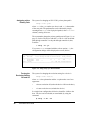
Specifying a Device
for setsp
To name a specific device in any setsp command, use the -l
option (note that this is a lowercase letter L, and not the number 1)
followed by the device's spd number, as expressed in the syntax
illustrations used in the remainder of this chapter as -l<x>. A
device's spd number is listed in the first column of the setsp -a
output (See setsp -a example on page 16).
Leaving out the -l option will apply the command to all of the
devices. However, more than one device must never be explicitly
specified in a given command. Also, whether you are applying the
configuration command to a single device or to all the devices,
only one parameter can be changed per command.
Chapter 3.
SVA Path Operation
25
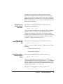
Assigning a New
Primary Path
The syntax for changing an SVA LUN’s primary data path is
setsp -l<x> -p<n>
where <x> is the spd number (see above) and <n> is the number
of the new path. The path number can be obtained by simply
counting down setsp’s list of physical paths (in the Path/disk
column), starting from zero.
The command to change the primary path shown in Figure 3-1, on
page 23, for the SVA device with the spd ID of 0 from its default
path through controller 7 to the path through controller 8, then,
would be:
# setsp -l0 -p1
If you run a setsp command with the verbose option (-v), the
configuration change will be displayed on screen (below)
# setsp -v -l0 -p1
===============================================================================
spd
Path/disk
Status Primary Exclude Buf Balance RtrCnt RtrDly FailBack
===============================================================================
0
c7t0d0/sd66
Good
32
0
20
3000
1
c8t0d0/sd88
Good
X
spd0 = c3t0d0
ID = "STK 9500 0000000010390000"
===============================================================================
Figure 3-2 Using setsp -p in Verbose Mode
Turning the
Exclusion Setting
Off and On
The syntax for changing the exclusion setting for a device is
setsp -l<x> -e{0|1}
where <x> is the spd number and the -e option takes one of two
arguments:
•
-e0 turns exclusion off (makes the device visible to the host);
•
-e1 turns exclusion on (excludes the device).
In a single-host configuration all devices should be visible to the
host. Devices can be included (or unexcluded) by using the
command.
# setsp -l all -e0
26
SVA Path User’s Guide
All devices may be included, as they present no conflicts.
However, in a multiple-host environment, where all spds are
visible to SVA Path on all hosts, spds must be either excluded or
included so that a host shares no spds. Use the ID number under
the spd column on the setsp -a output to identify devices. Do
not use the spdX number.
Redefining the
Buffer Pointer
Allocation
The syntax for changing the number of buffer pointers preallocated for a given device is
setsp -l<x> -n<n>
where <x> is the spd number (see “Specifying a Device for setsp”
on page 25) and <n> is the new value. The system must be
rebooted for this change to take effect. The number of buffer
pointers recommended for a given device is approximately equal
to the logical unit’s maximum useful queue depth; the default
value of 32 should suit most SVA devices.
Turning Load
Balancing On and
Off
The syntax for changing a device's load balancing mode is
setsp -l<x> -b{0|1}
where <x> is the spd number and the -b option takes one of two
arguments:
Changing the Retry
Count and Retry
Delay
•
-b0 turns load balancing off;
•
-b1 turns load balancing on.
The syntax for changing the retry count for a device is
setsp -l<x> -r<n>
where <x> is the numerical element of the spd number (see
“Specifying a Device for setsp” on page 25) and <n> is the number
of times a failed I/O will be retried on the primary path (after its
alternate paths have been tried unsuccessfully) before the path is
marked as failed (with a Status of Bad).
The syntax for changing the retry delay for a device is
setsp -l<x> -d<n>
Chapter 3.
SVA Path Operation
27
where <x> is the numerical element of the spd number and <n> is
the interval between the retries specified by the retry count
parameter.
Turning Failback Off
and On
The syntax for changing the a device’s failback mode is
setsp -l<x> -f{0|1}
where <x> is the spd number (see “Specifying a Device for setsp”
on page 25) and the -f option takes one of two arguments:
•
-f0 turns failback off;
•
-f1 turns failback on.
Dynamic Device Detection
You may be able to add new storage devices and place them under
SVA Path's control without requiring a reboot of the host. This is
also known as dynamic LUN allocation.
To add a fibre channel device to an existing path perform the
following steps after the devices are connected:
1.
Run ioscan and verify that the new storage resource is recognized by the system:
# ioscan -fn
2.
Run the insf command to generate the special device files
for the new storage:
# insf -e
3.
Have SVA Path scan the new device for alternate paths:
# sppath -v
4.
Create a SVA Path configuration file that includes the new
device:
# setsp -g
# setsp -T -l <new_spd_number>
28
SVA Path User’s Guide
5.
Start the new SVA Path device with:
# setsp -S -l <new_spd_number>
6.
Unexclude the new device:
# setsp -e0 -l <new_spd_number>
Chapter 3.
SVA Path Operation
29
30
SVA Path User’s Guide
Chapter 4. SVA Path Installation
This chapter describes how to install SVA Path for use with SVA
9500.
Installation of SVA Path in HP-UX is managed by the SD-UX
software management commands. Many of these tools (e.g.,
swinstall and swremove) can be run either from the command
line or from a Graphical User Interface (GUI). The following
instructions illustrate using the command line. However, the same
tasks can be accomplished through the GUI. For more information
on this alternative consult your HP-UX documentation for
swinstall and swremove.
Note: If your system contains current logical volumes, please
read the section titled "Reconfiguration for Existing Logical
Volumes" beginning on page 46 before installing SVA Path.
Installing SVA Path on HP-UX
Follow these steps to install the SVA Path driver and its supporting
files.
1.
Domain addresses must be automatically configured to be
set to zero (refer to “SVA Path Hardware Setup”, beginning
on page 5).
2.
Log in as root on the host on which you are installing SVA
Path.
Chapter 4.
SVA Path Installation
31
3.
Before installing SVA Path, it is imperative that the host is
able to see and access all storage devices through all
available paths. For example, if you have two HBAs and
redundant paths to your storage system, each logical drive
should be displayed twice by the command:
# ioscan -fnC disk
If you can’t see all available storage devices through every
path, verify that you have the latest fibre channel or SCSI
HBA drivers loaded on your system.
4.
If a previous version of SVA Path is installed on your
system, remove it before continuing with this installation.To
determine if an older version of SVA Path is present on your
system examine the output of the swlist command:
# /usr/sbin/swlist SVAPath
5.
To install the software insert the CD-ROM distribution and
log on as root. Mount the CD-ROM with the command:
# /usr/sbin/mount /dev/dsk/cXtYdZ/SD_CDROM
where /dev/dsk/cXtYdZ is the device special filename of
your CD-ROM.
6.
Before proceeding, refer to the README file in the directory
/SD_CDROM for information on any changes to the software
or installation procedure that may have occurred after this
manual was printed.
Caution: Before continuing, be aware that running swinstall
will rebuild your system kernel. You will have to reboot in order
to use SVA Path devices.
7.
Install SVA Path by becoming root and, from the
SD_CDROM directory, issue the ./install command.
Follow the onscreen instructions to completion.
Caution: The swinstall takes approximately 2.5 minutes to
complete. To ensure that the swinstall has adequate time to
32
SVA Path User’s Guide
complete all active processes, wait 3 minutes before pressing the
“Finish” button on the last panel of the install screens, and before
rebooting and unmounting the CDROM. (To monitor active
processes, type ps -ef | grep install and wait until all
processes have ended before rebooting the machine and
unmounting the CD.)
8.
Enter the appropriate system command to eject the
CDROM.
9.
Reboot the host.
10.
Verify that all available drives are seen by SVA Path by
running the command:
# setsp -a
11.
Edit any other application-specific files to reflect the new
device names. New device files— identical to the preinstallation device files, except for their controller
numbers—are generated during SVA Path installation for all
SVA devices (including those accessible by only a single
path). Any applications already configured to use the older
device files to access SVA LUNs must be reconfigured to
use the new pathnames (an example of this is given in the
instructions below for installing SVA Path with SVA
Administrator).
The installation is now complete.
Installing SVA Path with SVA Administrator
SVAA uses a designated LUN on the SVA for administrative
commands (rather than data storage) and a particular character
special device file (e.g., /dev/rdsk/c1t0d0s2) to access that
LUN. This is SVAA’s Extended Control and Monitoring (ECAM)
facility, and the LUN designated for its use is the ECAM device.
Before SVA Path is installed, make a note of this device name.
Chapter 4.
SVA Path Installation
33
Note: If SVA Path is installed after SVAA, SVA Path will
claim the SVAA device. Run the following commands,
which will cause SVA Path to ignore the specified device:
# sppath -I(cXtYdZ)
# setsp -T -l(n)
# setsp -g
Changes will take effect only after the next reboot of the
host.
After SVA Path is installed, in addition to its physical path(s) (e.g.,
/dev/rdsk/c1t0d0s2 and /dev/rdsk/c2t0d0s2 ), a virtual
path to the ECAM device will have been created along with an
additional device name (e.g., /dev/rdsk/c3t0d0s2), which
SVAA must be configured to use instead of the original ECAM
device name. To discover the new name for the ECAM device, run
setsp -a and look for the original device name among the
listings in the second column; the new device name appears in the
first column of the same entry, below the spd number. (An
example of setsp -a output is shown in Figure 3-4 on page 16.)
Consult your SVAA documentation for details on running SVAA’s
sibconfig command to reconfigure the ECAM device name.
Uninstalling SVA Path
1.
To remove SVA Path you need only enter the package
remove command from the root directory:
# /usr/sbin/swremove SVApath
2.
Restore any application-specific files that were modified
during the installation procedure.
3.
Restore the hardware configuration.
4.
Reboot the system.
Note: To remove the install files, remove the directory
/opt/storagetek/svapath.
34
SVA Path User’s Guide
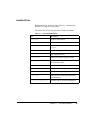
Installed Files
During installation, the files listed in Table 4-1, “Installed SVA
Path Files” are placed in your system.
All of these files will be removed if SVA Path is uninstalled.
Table 4-1
Installed SVA Path Files
File
Description
/sbin/spckd
Script to start spcheck
/usr/conf/master.d/spd
SVA Path driver
/usr/conf/lib/libusrdrv.a
archive file in which spd is
stored
/etc/sppath.conf
sppath configuration file
/etc/spd.conf
spd configuration file
/sbin/spcheck
Daemon to monitor change in paths
/sbin/sppath
qualifies and claims SVA storage devices
for SVA Path control
/sbin/setsp
configures SVA Path parameters
/sbin/init.d/spdaemon
script to start and stop the spmon daemon
/etc/rc.config.d/svapath
SVA Path startup configuration file
/sbin/spmon
monitors device paths and implements
load balancing
/sbin/rc1.d/SO99spdaemon
symbolic link to /sbin/init.d/spdaemon
Chapter 4.
SVA Path Installation
35
36
SVA Path User’s Guide
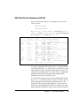
SVA Path Device Naming on HP-UX
Disk device filenames in HP-UX 10.x and higher have names in the
following format:
/dev/dsk/cXtYdZ
/dev/rdsk/cXtYdZ
The controller instance number (X), the disk drive’s SCSI ID
number (Y) and the SCSI LUN number (Z) can all be obtained from
the I and the H/W Path columns of ioscan -fn:
# ioscan -fn
Class
I H/W Path
Driver
S/W State H/W Type Description
========================================================================
bc
2 10
ccio
CLAIMED
BUS_NEXUS I/O Adapter
ext_bus
0 10/0
c720
CLAIMED
INTERFACE GSC Fast/Wide SCSI Interface
target
0 10/0.1
tgt
CLAIMED
DEVICE
disk
13 10/0.1.0
sdisk
CLAIMED
DEVICE
STK 9500
/dev/dsk/c0t1d0
/dev/rdsk/c0t1d0
disk
14 10/0.1.1
sdisk
CLAIMED
DEVICE
STK 9500
/dev/dsk/c0t1d1
/dev/rdsk/c0t1d1
ext_bus
3 10/8
c720
CLAIMED
INTERFACE GSC Fast/Wide SCSI Interface
target
5 10/8.0
tgt
CLAIMED
DEVICE
disk
5 10/8.0.0
sdisk
CLAIMED
DEVICE
STK 9500
/dev/dsk/c3t0d0
/dev/rdsk/c3t0d0
disk
6 10/8.0.1
sdisk
CLAIMED
DEVICE
STK 9500
/dev/dsk/c3t0d1
/dev/rdsk/c3t0d1
ba
0 10/12
bus_adapter CLAIMED
BUS_NEXUS Core I/O Adapter
ext_bus
5 10/12/0
CentIf
CLAIMED
INTERFACE Built-in Parallel Interface
/dev/c5t0d0_lp
ext_bus
4 10/12/5
c720
CLAIMED
INTERFACE Built-in SCSI
target
7 10/12/5.2
tgt
CLAIMED
DEVICE
disk
3 10/12/5.2.0 sdisk
CLAIMED
DEVICE
TOSHIBA CD-ROM XM-4101TA
/dev/dsk/c4t2d0
/dev/rdsk/c4t2d0
In a typical, single-path disk storage system, each physical disk is
represented in the host’s /dev directory by two special device files
representing the character and block mode device instances. For
simplicity, we will discuss this set of device files as a single device
filename and disregard the first part of the pathnames that
distinguish between raw and block modes.
As a layered driver that runs on top of the standard HP-UX disk
driver (sdisk), SVA Path creates its own device files for devices,
and it is through these filenames that applications access the
underlying devices. When multiple paths to a single device are
present, so would multiple device files be present, one for each
path via the native disk driver. In these cases, which are typical of
Chapter 4.
SVA Path Installation
37
SVA Path installations, SVA Path creates a single additional
device filename for applications to access the device and manages
the original device files transparently to those applications.
Note: It is the virtual device file that will be used by applications
to access that device. The original, redundant data paths should
never be used to access the device, or the data it contains could be
corrupted.
For example, an SVA might present a single physical disk device
to the HP-UX host as c1t0d0 and c2t0d0. SVA Path creates a
third device file named c81t0d0 that is used by applications to
access the storage. It blocks applications’access to the original two
device files.
How Device
Filenames Are
Chosen
In order to provide interoperability with complementary storage
management software (e.g., Logical Volume Manager), SVA Path
uses standard HP-UX device names in the form cXtYdZ, where X
represents a controller or HBA number, Y represents a SCSI target
number, and Z represents a SCSI LUN.
When SVA Path adds new device files to the system and changes
the device names by which pre-existing devices must be accessed,
the new device files, in order to be as easily understood as
possible, retain the SCSI target and LUN from the original device
files.
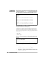
For example, a set of physical devices might originally be
accessible via HBAs c1 and c2. SVA Path will create new, virtual
disk device files whose names start with c81 and which have the
same target and LUN numbers as the original device files.
Therefore, a device originally accessible via the fibre channel or
SCSI disk driver device files c1t4d0 and c2t4d0 will, after SVA
38
SVA Path User’s Guide
Path is installed, be accessed through the SVA Path device file
c81t4d0 (Figure 4-1).
Host Applications
c81
Virtual
Controller
SVA Path creates a virtual controller and presents
the device to host applications as a single device.
SVA Path
SVA Path sees both device filenames for the
disk as presented by each of the two controllers
c1
Physical
Controller
(HBA1)
c2
Physical
Controller
(HBA2)
t4d0
Figure 4-1
SVA Path Device Filename Management
If the target and LUN numbers assigned to the device are different
on each physical path, SVA Path uses the target and LUN number
associated with the lowest numbered HBA. If a device is
originally accessible as c1t4d0 and c2t2d1, for example, the
c1t4d0 device name has the lower controller number (c1) and
thus SVA Path takes the target (t4) and LUN (d0) number from it
to construct the new device name, c81t4d0.
Chapter 4.
SVA Path Installation
39
If there are more than one set of redundant paths, there could be
more than one device with a given target and LUN number. For
this reason, SVA Path creates a different virtual HBA for each set
of redundant physical HBAs. For example, if one device is
accessible via c1t0d0 and c2t0d0, and another device is
accessible via c3t0d0 and c4t0d0, SVA Path would create two
new device files c81t0d0 (for c1t0d0 and c2t0d0) and
c83t0d0 (for c3t0d0 and c4t0d0).
Devices without
Redundant Paths to
the Host
SVA Path creates virtual device files for all supported devices and
blocks access to them through their original device filenames
whether or not they are accessible via redundant paths. Virtual
device files are created for devices that have only one physical
path for two reasons:
1.
a device could actually have more than one path but only one
was functional at the time that SVA Path was installed
2.
the device could be part of a SAN configuration where it is
necessary to prohibit applications on the local host from
accessing the device because the device was assigned to
another host on the SAN.
Logical Volume Manager
Logical Volume Manager (LVM) is a disk management system
provided by HP in all versions of HP-UX 10.x and HP-UX 11.x.
The LVM allows you to manage storage as logical volumes. This
section of the manual describes some concepts used by the LVM
and explains how to create and expand logical volumes. For more
detailed information, please consult the man pages for lvm(7)and
the HP-UX System Administration Tasks manual.
As with many systems administration tasks you can use the HPUX System Administration Manager (SAM) to create and
maintain some logical volumes. However, because SAM cannot
recognize SVA Path devices, you must use the LVM commands
pvcreate, vgcreate and lvcreate.
40
SVA Path User’s Guide
This section shows how to create a new volume group and add a
disk drive to it, using example screens from an HP 800 system
running HP-UX 11.00.
Definitions of
Common Terms
The following terms will be used throughout this section:
•
Volume Group. Volume groups are HP-UX's method for
dividing and allocating disk storage space. Volume groups
can be used to partition a disk drive into smaller logical
volumes (see below). There is a default limit of 10 volume
groups per system; see the HP-UX System Administration
Tasks manual for information on increasing this limit. The
number of logical volumes in a volume group is limited to
255.
•
Logical Volume. Each volume group is divided into logical
volumes, which can be accessed as either character or block
devices and which contain their own filesystems.
•
Physical Volume. In volume groups, the physical disk
drives are designated as physical volumes.
•
Physical Extent. Each physical volume is divided into units
called physical extents; these units are 4 MB by default, and
can range in size from 1 MB to 256 MB. The size of physical
extents is a property of the volume group and is the same for
all physical volumes in the volume group.
Chapter 4.
SVA Path Installation
41
Preparing the
Volume Group
Device files for each volume group on an HP 9000 system reside
in directories with names /dev/vg*. The following example lists
the volume groups on an HP800 system running HP-UX 11.00
# ls -l /dev/vg*
/dev/vg00:
total 0
crw-rw-rw- 1 rootroot 64 0x000000 Dec 23 15:23 group
brw-r-----1 root root 64 0x000001 Dec 23 15:23 lvol1
brw-r-----1 rootroot 64 0x000002 Dec 23 15:23 lvol2
brw-r-----1 root root 64 0x000003 Dec 23 15:23 lvol3
crw-r-----1 root root 64 0x000001 Dec 23 15:23 rlvol1
crw-r-----1 root root 64 0x000002 Dec 23 15:23 rlvol2
crw-r-----1 root root 64 0x000003 Dec 23 15:23 rlvol3
/dev/vg01:
total 0
crw-rw-rw- 1 root root 64 0x010000 Jan 11 14:15 group
brw-r-----1 root root 64 0x000001 Jan 23 15:23 lvol1
crw-r-----1 root root 64 0x000001 Jan 23 15:23 rlvol1
Two volume groups, vg00 and vg01, already exist on this system.
To prepare to create a new volume group:
Create the device directory that will contain the logical volume,
using the next available volume group number. In this example,
the next volume group number is 2, so the group should be named
/dev/vg02:
# cd /dev
# mkdir vg02
Use mknod to create create a device file named group in the new
directory:
# mknod /dev/vg02/group c 64 0x020000
# ls -lg /dev/vg02
total 0
crw-rw-rw- 1 sys64 0x020000 May 18 15:51 group
In the above example, the mknod command has the following
arguments:
42
•
the full pathname to the new device file group;
•
the letter c to indicate a character device file;
•
the number 64, which is the major number for the driver that
manages volume groups;
SVA Path User’s Guide
•
Creating the
Physical Volume
a minor number of the form 0xNN0000, where NN is the twodigit hexadecimal representation of the volume group
number (here, 02).
Before you create a volume group, the disk drive you want to add
to the group must be made a physical volume with pvcreate:
# pvcreate /dev/rdsk/c0t2d0
Physical volume "/dev/rdsk/c0t2d0" has been
successfully created
Creating the Volume
Group
To create the volume group and associate the physical volume
with it, use the vgcreate command:
# vgcreate /dev/vg02 /dev/dsk/c0t2d0
Increased the number of physical extents per
physical volume to 2167.
Volume group "/dev/vg02" has been successfully
created
Volume Group configuration for /dev/vg02 has
been saved in /etc/lvmconf/vg02.conf
vgcreate takes as its first argument the pathname of the volume
group directory, and as its second argument the full pathname of
the block device file (not the character device file, which was used
to create the physical volume) of the disk drive.
Chapter 4.
SVA Path Installation
43
To verify the creation and view the volume group characteristics,
use the vgdisplay command:
# vgdisplay vg02
--- Volume groups --VG Name
VG Write Access
VG Status
Max LV
Cur LV
Open LV
Max PV
Cur PV
Act PV
Max PE per PV
VGDA
PE Size (Mbytes)
Total PE
Alloc PE
Free PE
Total PVG
/dev/vg02
read/write
available
255
0
0
16
1
1
2167
2
4
2167
0
2167
0
In the output of vgdisplay, the Total PE field gives the number
of physical extents in the volume group. The size of each physical
extent is given in the PE Size field (the default is 4 MB), so the
total capacity of this volume group is 2167 x 4 MB = 8668 MB.
The Alloc PE field shows the number of physical extents
allocated to logical volumes. At this point, the Alloc PE field is
zero because we have not assigned any of this volume group’s
capacity to logical volumes.
Please refer to the man page for vgcreate for more information
on creating volume groups.
Creating Logical
Volumes
To create a logical volume within the volume group, use the
lvcreate command with the -L option to specify the size of the
logical volume in megabytes. The logical volume size should be a
44
SVA Path User’s Guide
multiple of the physical extent size that is 4 MB by default. In the
example below, a volume group of 4092 MB is created:
# lvcreate -L 4092 /dev/vg02
Logical volume "/dev/vg02/lvol1" has been
successfully created with character device
"/dev/vg02/rlvol1".
Logical volume "/dev/vg02/lvol1" has been
successfully extended.
Volume Group configuration for /dev/vg02 has
been saved in /etc/lvmconf/vg02.conf
In the example, lvcreate is followed on the command line by
the -L option and the size of the logical volume in megabytes,
then by the pathname of the volume group directory.
Both character and block device files for the new logical volume
are created in the volume group directory:
# ls /dev/vg02
group
lvol1
rlvol1
Use these names to access the logical volumes. For example, to
create an hfs filesystem on logical volume lvol1 in volume group
vg02, you would use the following command:
# /etc/newfs -F hfs /dev/vg02/rlvol1
Chapter 4.
SVA Path Installation
45
The Free PE field in the vgdisplay output shows that the
number of free physical extents in the volume group has
decreased:
# vgdisplay vg02
--- Volume groups --VG Name
/dev/vg02
VG Write Access
read/write
VG Status
available
Max LV
255
Cur LV
1
Open LV
1
Max PV
16
Cur PV
1
Act PV
1
Max PE per PV
2167
VGDA
2
PE Size (Mbytes)
4
Total PE
2167
Alloc PE
1023
Free PE
1144
Total PVG
0
You can continue to create logical volumes with the lvcreate
command until the Free PE field is 0, which indicates that the
volume group has been completely allocated to logical volumes.
Reconfiguration for
Existing
Applications
Any physical device supported by SVA Path and in use prior to
SVA Path installation will, from the perspective of host
applications, be renamed during SVA Path installation.
Applications will need to be redirected to the new filenames, by
modifying the configuration of the individual application to reflect
the new device names.
SVA Path does not support the LVM feature of alternative links to
physical volumes (pv-links). If you have an existing volume
group that was created with alternative links you must re-import it
using the SVA Path device names of the physical volumes as
explained below. SVA Path will provide the same level of
protection against the failure of a single path.
Reconfiguration for
Existing Logical
Volumes
46
Since physical devices are renamed during SVA Path installation,
if those physical devices are part of existing logical volumes, your
system will not be able to locate the physical devices after SVA
Path is installed. You will need to follow the steps listed below to
SVA Path User’s Guide
first export the volume group and them import it using the new
special device filenames that SVA Path assigns.
In the following example there are two logical volumes in a
volume group, vg02.
1.
Make note of the minor number of the filename group for
the volume group:
# ls -l /dev/vg02/group
crw-rw-rw- 1 root sys 64 0x020000 Jun 23 13:02 /dev/vg02/group
You will need this information to recreate the volume group later
in this process. In this example the minor number for logical
volume vg02 is 0x020000.
2.
Determine the names of physical volumes that make up this
volume group. Examine the last part of the output of the
vgdisplay command, where the physical volumes that
make up the volume group are listed. In this example, only
the pertinent output is shown:
# vgdisplay -v /dev/vg02
--- Volume groups --VG Name
/dev/vg02
--- Physical volumes --PV Name
/dev/dsk/c6t0d0
PV Status
available
Total PE
16747
Free PE
16497
PV Name
PV Status
Total PE
Free PE
/dev/dsk/c6t0d1
available
16749
16749
The volume group is composed of physical volumes
/dev/dsk/c6t0d0 and /dev/dsk/c6t0d1.
Chapter 4.
SVA Path Installation
47
3.
Unmount all of the logical volumes in the volume group and
deactivate the volume group by entering the following
command:
# vgchange -a n /dev/vg02
4.
Remove the volume group from the system configuration
file and delete the associated device files for the logical
volumes:
# vgexport /dev/vg02
5.
Recreate the directory and the device filename for the
volume group using the same minor number of the original
volume group:
# mkdir /dev/vg02
# mknod /dev/vg02/group c 64 0x020000
6.
Activate the SVA Path devices with:
# setsp -S
7.
Display the SVA Path device names with:
# setsp -a
=============================================================================
spd
Path/disk
Status Primary Exclude Buf Balance RtrCnt RtrDly FailBack
=============================================================================
0
c6t0d0
Good
X
32
0
20
3000
1
c7t0d0
Good
spd0 = c86t0d0
ID = "STK 9500 0000000010390000"
=============================================================================
1
c6t0d1
Good
32
0
20
3000
1
c7t0d1
Good
X
spd1 = c86t0d1
ID = "STK 9500 0000000010390001"
48
SVA Path User’s Guide
8.
Select the SVA Path devices that correspond to the original
device filenames of the physical volumes of the volume
group. In this example they are /dev/dsk/c86t0d0 and
/dev/dsk/c86t0d1. Use these filenames in the vgimport
command to recreate the configuration information for the
volume group:
# vgimport -v /dev/vg02 /dev/dsk/c86t0d0
/dev/dsk/c86t0d1
Beginning the import process on Volume Group
"/dev/vg02".
Logical volume "/dev/vg02/lvol1" has been
successfully created with lv number 1.
Logical volume "/dev/vg02/lvol2" has been
successfully created with lv number 2.
Volume group "/dev/vg02" has been successfully
created.
Warning: A backup of this volume group may not
exist on this machine.
Please remember to take a backup using the
vgcfgbackup command after activating the volume group.
9.
Activate the volume group and backup the configuration:
# vgchange -a y /dev/vg02
Activated volume group
Volume group "/dev/vg02" has been successfully changed.
# vgcfgbackup -u /dev/vg02
Volume Group configuration for /dev/vg02 has been saved in
/etc/lvmconf/vg02.conf
You can now remount your filesystems and restart the applications
that use them.
Chapter 4.
SVA Path Installation
49
50
SVA Path User’s Guide
Chapter 5. Diagnosing Errors
Comparing setsp -a with System Events
SVA Path necessarily interfaces with system components at the
I/O path level, which does not support sophisticated device error
reporting. The application reports failed I/O to
/var/adm/syslog/syslog.log as well as when:
•
a data path is found to have stopped functioning
•
I/O is redirected to an alternate path
•
the failed path resumes functioning.
Whether a path failure is intermittent or is caused by a hardware
failure can usually be deduced from the events listed in
/var/adm/syslog/syslog.log, and a faulty device can be
located physically by cross referencing the output of setsp -a.
Figure 5-1, “Example setsp -a Output for a Fully Functioning
System” shows the example configuration used in this section.
# setsp -a
===============================================================================
spd
Path/disk
Status Primary Exclude Buf Balance RtrCnt RtrDly FailBack
===============================================================================
0
c6t0d0
Good
X
32
0
20
3000
1
c7t0d0
Good
spd0 = c86t0d0
ID = "STK 9500 0000000010390000"
===============================================================================
1
c6t0d1
Good
X
32
0
20
3000
1
c7t0d1
Good
spd1 = c86t0d1
ID = "STK 9500 0000000010390001"
===============================================================================
2
c6t0d2
Good
X
32
0
20
3000
1
c7t0d2
Good
spd2 = c86t0d2
ID = "STK 9500 0000000010390002"
===============================================================================
Figure 5-1 Example setsp -a Output for a Fully Functioning System
Chapter 5.
Diagnosing Errors
51
Cable Failure Errors
Figure 5-2, “Messages Generated When a Cable Is Pulled”
illustrates error messages that will occur in the file
/var/adm/syslog/syslog.log. The hardware path of the
affected fibre channel interface is identified as "0/5/0/0". Using
the output of the ioscan command in Figure 5-3, “Excerpt of
ioscan -fn output”, the affected devices can be identified. In this
example they are /dev/dsk/c6t0d0, /dev/dsk/c6t0d1, and
/dev/dsk/c6t0d2.
Jun 30 14:54:36 n4000 vmunix: ALERT: fcT1 (1, 712251,
Channel Driver received an interrupt indicating a Link
Manager Status Register is 0x980010D0.
Jun 30 14:55:58 n4000 vmunix: ALERT: fcT1 (1, 720484,
Channel Driver received an interrupt indicating a Link
Manager Status Register is 0x980010D0.
Jun 30 14:56:28 n4000 vmunix: ALERT: fcT1 (1, 735458,
Channel Driver received an interrupt indicating a Link
Manager Status Register is 0x980010D0.
Jun 30 14:57:31 n4000 vmunix: spd0: path 0 error
0/5/0/0) Fibre
Failure. The Frame
0/5/0/0) Fibre
Failure. The Frame
0/5/0/0) Fibre
Failure. The Frame
Figure 5-2 Messages Generated When a Cable Is Pulled
In the final message above, spd0 can be located in the output from
setsp -a to determine that the affected device is c60t0d0. The
message also calls out path 0 which corresponds to
c60t0d0/sd66 in the setsp output, which matches the device
name (sd66) called out in the earlier messages. (The paths
associated with a SVA Path device [spd] are numbered from 0 to
n-1 and are listed in that order in the setsp -a output, so, for
example, spd2 path 1 is c8t0d2 in the setsp -a output above).
# ioscan -fn
fc
0 0/5/0/0
fcT1
HP Fibre Channel Mass Storage Adapter
target
5
0/5/0/0.8.0.255.0.0
CLAIMED
tgt
disk
50 0/5/0/0.8.0.255.0.0.0
sdisk
disk
51 0/5/0/0.8.0.255.0.0.1
sdisk
disk
60 0/5/0/0.8.0.255.0.0.2
sdisk
CLAIMED
DEVICE
CLAIMED
DEVICE STK 9500
/dev/dsk/c6t0d0
/dev/rdsk/c6t0d0
CLAIMED
DEVICE STL 9500
/dev/dsk/c6t0d1
/dev/rdsk/c6t0d1
CLAIMED
Figure 5-3 Excerpt of ioscan -fn output
52
INTERFACE
DEVICE STK 9500
Errors for other spd devices, representing the same physical I/O
path that was interrupted by the pulled cable, will be reported, as
shown in Figure 5-4, “Additional Messages for the Same Pulled
Cable”.
Jun 30 14:58:28 n4000 vmunix: ALERT: fcT1 (1, 735458,
Channel Driver received an interrupt indicating a Link
Manager Status Register is 0x980010D0.
Jun 30 14:58:31 n4000 vmunix: spd2: path 0 error
Jun 30 14:58:36 n4000 vmunix: ALERT: fcT1 (1, 712251,
Channel Driver received an interrupt indicating a Link
Manager Status Register is 0x980010D0.
Jun 30 14:58:40 n4000 vmunix: spd1: path 0 error
0/5/0/0) Fibre
Failure. The Frame
0/5/0/0) Fibre
Failure. The Frame
Figure 5-4 Additional Messages for the Same Pulled Cable
Even when an spd device is idle, a SCSI Test Unit Ready
command is sent periodically to the device to confirm that it is
functioning. A failure of this test is reported in the syslog.log file
as illustrated in Figure 5-4, “Additional Messages for the Same
Pulled Cable”.
Failover Error Reporting
/var/adm/syslog/syslog.log records failover events as
well..
Jun 29 13:53:44 n4000 vmunix: spd0: path failover from 0 to 1.
Figure 5-5 The Failover Event
The event in Figure 5-5, “The Failover Event” records that I/O for
the device spd0 will be redirected from path 0 (c6t0d0) to path
1 (c7t0d0 ), the alternate path. The output from setsp -a (Figure
5-6, “setsp -a Output after the Failed Path Is Detected”) now
Chapter 5.
Diagnosing Errors
53
shows that every device’s path 0 (those corresponding to device
filenames beginning c7) have a Status designation of Bad.
# setsp -a
===============================================================================
spd
Path/disk
Status Primary Exclude Buf Balance RtrCnt RtrDly FailBack
===============================================================================
0
c6t0d0
Good
X
32
0
20
3000
1
c7t0d0
Good
spd0 = c86t0d0
ID = "STK 9500 0000000010390000"
===============================================================================
1
c6t0d1
Bad
X
32
0
20
3000
1
c7t0d1
Good
spd1 = c86t0d1
ID = "STK 9500 0000000010390001"
===============================================================================
2
c6t0d2
Bad
X
32
0
20
3000
1
c7t0d2
Good
spd2 = c86t0d2
ID = "STK 9500 0000000010390002"
===============================================================================
Figure 5-6 setsp -a Output after the Failed Path Is Detected
Recovering from a Failure
Path failures generate a lot of output, resulting primarily from the
disk driver’s attempts at error recovery.
Finally, when the cable is plugged back in, SVA Path will detect
that the primary I/O path for spd0 is back to normal and redirect
data over that path (Figure 5-7, “The Failback Event”).
Jun
Jun
Jun
Jun
30
30
30
30
15:29:31
15:29:31
15:29:31
15:29:31
n4000
n4000
n4000
n4000
vmunix:
vmunix:
vmunix:
vmunix:
spd1:
spd2:
spd3:
spd1:
path
path
path
path
0 ok
0 ok
0 ok
failover from 1 to 0.
Figure 5-7 The Failback Event
The other paths are returned to Status Good, as well.
The output of setsp -a will return to normal (Figure 5-1, on
page 51).
54
READER'S
COMMENT
FORM
Manual PN:
Manual Name:
Please check or fill in the items; adding explanations/comments in the space provided.
Which of the following terms best describes your job?
Field Engineer
Engineer
Instructor
Manager
Mathematician
Operator
Programmer
Sales Representative
Student/Trainee
Systems Analyst
Systems Engineer
Other (explain below)
Reference manual
Student/Trainee
Instructor text
How did you use this publication?
Introductory text
Other (explain)
Did you find the material easy to read and understand?
Yes
No (explain below)
Did you find the material organized for convenient use?
Yes
No (explain below)
Specific criticisms (explain below):
Clarifications on pages
Additions on pages
Deletions of pages
Errors on pages
Explanations and other comments:
Note: Staples can cause problems with automated mail sorting equipment. Please use pressure sensitive or other
gummed tape to seal this form. If you would like a reply, please supply your name and address on the reverse side
of this form.
Chapter 5.
Diagnosing Errors
Thank you for your cooperation. No postage stamp necessary if mailed in the U.S.A.
55
TO COMPLY WITH POSTAL REGULATIONS, FOLD EXACTLY ON DOTTED LINES AND TAPE (DO NOT STAPLE)
NO POSTAGE
NECESSARY
IF MAILED
IN THE
UNITED STATES
BUSINESS REPLY MAIL
FIRST CLASS
PERMIT NO. 2
LOUISVILLE, CO U.S.A.
POSTAGE WILL BE PAID BY ADDRESSEE
STORAGE TECHNOLOGY CORPORATION
ENTERPRISE DISK INFORMATION DEVELOPMENT
ONE STORAGETEK DRIVE
LOUISVILLE CO 80028-2201
FOLD HERE AND TAPE
FOLD HERE AND TAPE
DO NOT STAPLE
If you would like a reply, please print:
Your Name:
Company Name:
56Address:
Street
Department:
Printed in U.S.A