1
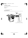
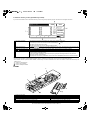
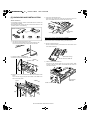
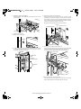
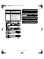
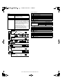
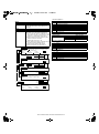
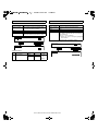
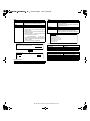
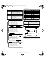
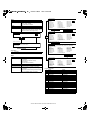
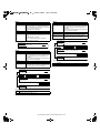
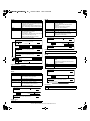
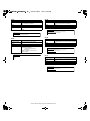
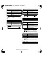
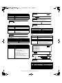
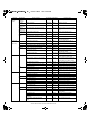
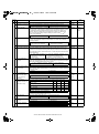
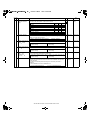
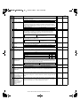
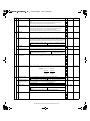
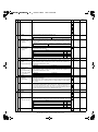
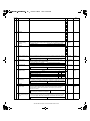
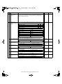
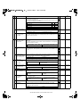
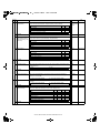
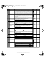
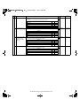
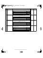
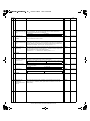
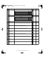
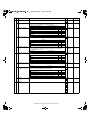
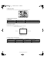
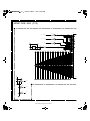
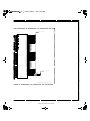
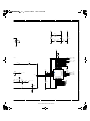
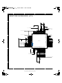
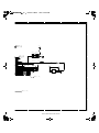
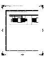
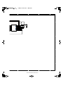
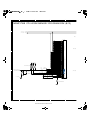
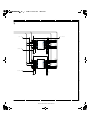
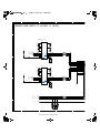
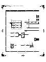
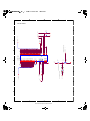
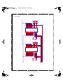
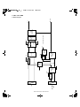
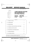
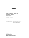
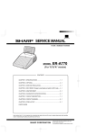
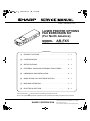
( "#
$%&'
6) Reattach the MFP control PWB unit.
Reattach the MFP control PWB unit to the printer and secure it with
the two screws.
8) Attach the FAX power cord to the printer.
Remove the screw of the connector cover for connection of FAX
power supply connector on the main unit of the printer, and remove
the connector cover. Then, connect the FAX power supply connector
to the connector on the main unit of the printer and tighten the three
screws on the connector to secure the connector.
Ensure that the FAX power switch is in the OFF position.
Screw
Connector cover
FAX power switch
Screw
OFF
Screw
7) Attach the FAX box unit.
<1>Secure screw A to the rack.
Screw A
Screw
FAX power cord
<2> Hang the positioning hole on the side of the FAX box unit on screw
A, slide the FAX box unit toward the rack, and secure the rack and
the FAX box unit with two screws B.
9) Connect each connector of the FAX box unit.
Connect the FAX interface cable to the FAX box unit and the MFP
control unit and then connect the line cable to the FAX box unit.
Connect the scanner cable that has been removed in step 2).
Scanner cable
FAX box unit
Rack
Screw A
Positioning hole
Line cable
TEL
LINE
Screws B
FAX interface cable
10) Turn the main switch of the printer to ON.
Insert the power plug of the printer to the outlet and turn the main
switch and the FAX power switch of the FAX box unit to ON.
AR-FX5 UNPACKING AND INSTALLATION 5-2