1
Functional description
5.6 Functions
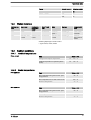
The following functions can be selected using the SET menu:
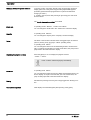
"Calibrate" function: (Identity code, stroke length adjustment: manual +
calibration) The pump can also be operated in the calibrated state in all
operating modes. In this case, the corresponding continuous displays can
then indicate the metering volume or the capacity directly. Calibration is
maintained within a stroke rate range of 0 - 180 strokes/min. The calibra‐
tion is also maintained when the stroke length is altered by up to ±10 %
scale divisions.
"Auxiliary frequency" function: Enables a freely selectable and program‐
mable stroke rate to be switched on in the “SET” menu, which can be
controlled via the "External Control" terminal. This auxiliary frequency has
priority over the operating mode stroke rate settings .
"Flow" function: Stops the pump when the flow is insufficient, provided a
dosing monitor is connected. The number of defective strokes, after which
the pump is switched off, can be set in the “SET” menu.
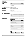
The following functions are available as standard:
"Level switch" function: Information about the liquid level in the chemical
feed container is reported to the pump control. To do so, a two-stage level
switch must be fitted; it is connected to the "Level switch" terminal.
"Pause" function: The pump can be remotely stopped via the "External
Control" terminal. The "Pause" function only works via the "External Con‐
trol" terminal.
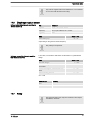
The following functions are triggered by a key press:
"Stop" function: The pump can be stopped without disconnecting it from
the power supply by pressing the [STOP/START] key.
"Prime" function: Priming (short-term transport at maximum frequency) can
be triggered by simultaneous pressing of the two arrow keys in the "Stroke
rate" continuous display.
5.7 Options
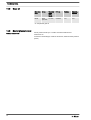
Relay option
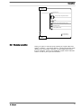
The pump has two connecting options (not with PROFIBUS® or timer):
Option "Fault indicating relay" or "Power relay": In the event of fault sig‐
nals, warning signals or tripped level switches, the relay connects to com‐
plete an electric circuit (for alarm horns etc.). The relay can be retrofitted
via a knock-out in the drive unit.
"Fault indicating and pacing relay" option In addition to the fault indicating
relay, the pacing relay can be used to make a contact every stroke. The
relay can be retrofitted via a knock-out in the drive unit.
19