1
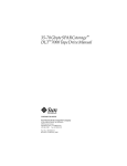
CERTANCE
Online User's Guide
LTO - 1 / LTO - 2 Ta p e D r i ve s
i
Copyright and Trademarks
Copyright © 2003 by Certance LLC. All Rights Reserved.
Part Number 50001007
August 2003
Certance and the Certance logo are trademarks of Certance LLC. Seagate is a trademark of Seagate Technology LLC. Other product names are trademarks or registered trademarks of their respective owners.
Certance reserves the right to change, without notice, product offerings or specifications. No part of this publication may be reproduced in any form without written permission from Certance LLC.
Certance provides this manual “as is,” without warranty of any kind, either expressed or implied, including, but
not limited to, the implied warranties of merchantability and fitness for a particular purpose. Certance reserves
the right to change, without notification, the specifications contained in this manual.
Certance assumes no responsibility for the accuracy, completeness, sufficiency, or usefulness of this manual, nor
for any problem that might arise from the use of the information in this manual.
Warnings
All safety and operating instructions should be read before this product is operated, and should be retained for
future reference. This unit has been engineered and manufactured to assure your personal safety. Improper use
can result in potential electrical shock or fire hazards. In order not to defeat the safeguards, observe the following basic rules for installation, use and servicing.
CAUTION: This symbol should alert the user to the presence of “dangerous voltage” inside the
product that might cause harm or electric shock.
Caution! Risk of electric shock! Do not open!
To reduce the risk of electric shock, do not remove the cover (or back). No user-serviceable parts
are inside. Refer servicing to qualified service personnel.
•
Heed warnings — All warnings on the product and in the operating instructions should be adhered to.
•
Follow instructions — All operating and use instructions should be followed.
•
Ventilation — The product should be situated so that its location or position does not interfere with proper
ventilation.
•
Heat — The product should be situated away from heat sources such as radiators, heat registers, furnaces, or other heat producing appliances.
•
Power sources — The product should be connected to a power source only of the type directed in this
document or as marked on the product.
•
Power cord protection — The power cord should be routed so that it is not likely to be walked on or
pinched by items placed upon or against it, paying particular attention to the cord at the wall receptacle,
and the point where the cord exits from the product.
•
To complete the disconnection of the electricity, please remove the power (electric) cord and the SCSI
cable from their connections in the back of the product. The plugs should be placed near the product for
easy access.
•
Object and liquid entry — Care should be taken to insure that objects do not fall and liquids are not
spilled into the product's enclosure through openings.
•
Servicing — The user should not attempt to service the product beyond that described in the operating
instructions. All other servicing should be referred to qualified service personnel.
Precautions
•
Do not use oil, solvents, gasoline, paint thinners, or insecticides on the unit.
•
Do not expose the unit to moisture or to temperatures higher than 151 °F (66 °C) or lower than
-40 °F (-40°C).
•
Keep the unit away from direct sunlight, strong magnetic fields, excessive dust, humidity, and
electronic/electrical equipment, which generate electrical noise.
•
Hold the power cord by the head when removing it from the AC outlet; pulling the cord can damage the
internal wires.
•
Use the unit on a firm level surface free from vibration, and do not place anything on top of the unit.
FCC Notice
This equipment generates and uses radio frequency energy and, if not installed and used properly — that is, in
strict accordance with the manufacturer's instructions — may cause interference to radio communications or
radio and television reception. It has been tested and found to comply with the limits for a Class B computing
device in accordance with the specifications in Part 15 of FCC Rules, which are designed to provide reasonable protection against such interference in a residential installation. However, there is no guarantee that interference will not occur in a particular installation. If this equipment does cause interference to radio or television
reception, which can be determined by turning the equipment on and off, you are encouraged to try to correct
the interference by one or more of the following measures:
•
Reorient the receiving antenna.
•
Relocate the computer with respect to the receiver.
•
Move the computer into a different outlet so that the computer and receiver are on different branch circuits.
If necessary, you should consult the dealer or an experienced radio/television technician for additional suggestions. You may find the booklet, How to Identify and Resolve Radio-TV Interference Problems, prepared by the
Federal Communications Commission, helpful. This booklet (Stock No. 004-000-00345-4) is available from the
U.S. Government Printing Office, Washington, DC 20402.
WARNING: Changes or modifications made to this equipment, which have not been expressly
approved by Certance, may cause radio and television interference problems that could void
the user's authority to operate the equipment.
Further, this equipment complies with the limits for a Class B digital apparatus in accordance with Canadian
Radio Interference Regulations.
Cet appareil numérique de la classe B est conforme au Règlement sur brouillage radioélectrique, C. R. C., ch.
1374.
The desktop device drive described in this manual requires shielded interface cables to comply with FCC emission limits.
WARNING: To prevent fire or electrical shock hazard, do not expose the unit to rain or moisture.
To avoid electrical shock, do not open the cabinet.
Refer servicing to qualified personnel.
Contents
Chapter 1 - Introduction .................................................. 10
Features ............................................................................. 11
Using This Guide .................................................................. 12
Chapter 2 - Installation (and Quick Start) ..................... 13
Introduction ......................................................................... 13
Quick Start Guide ................................................................. 13
Unpacking and Inspection ...................................................... 15
Internal Tape Drive Guidelines and Cautions .............................. 15
Drive Installation Instructions ................................................... 16
Installing an Internal LTO-1 or LTO-2 Drive .................................. 16
Installing an Internal LTO-1 Fibre Channel Drive ........................... 23
Installing a Desktop Drive ....................................................... 28
Chapter 3 - Operation ..................................................... 31
Understanding the Front Panel Display ...................................... 31
Blink Codes ......................................................................... 32
Using LTO Cartridges ............................................................ 34
Drive Maintenance ............................................................... 36
Parking the Drive for Shipping ................................................. 37
Chapter 4 - Theory ........................................................... 38
Track Layout ........................................................................ 38
Recording Method ................................................................ 39
Data Buffer .......................................................................... 40
Data Integrity ....................................................................... 40
Data Compression ................................................................ 42
Chapter 5 - Specifications ............................................... 44
Physical Specifications ........................................................... 44
Power Specifications ............................................................. 47
Drive Performance Specifications ............................................. 48
Environmental Requirements .................................................... 49
Reliability ............................................................................ 50
vi
Mean Time Between Failures ................................................... 50
LTO Cartridge Specifications ................................................... 51
Regulatory Compliance .......................................................... 52
Chapter 6 - Unix Settings ................................................ 55
A Word About SCSI Controllers ............................................... 55
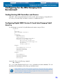
Configuring for the DEC/Compaq Unix Environment .................... 56
Configuring for the Sun Environment
(Solaris 2.4, 2.5, 2.6, 7, 8, and 9) ....................................... 57
Configuring for the IBM AIX Environment (AIX Version 4.1.x and later) 59
Configuring for SCO Open Server 5.0.x .................................. 60
Configuring for Linux ............................................................. 62
Configuring for SGI Irix ......................................................... 63
Configuring for HP-UX 11.0 .................................................... 64
Chapter 7 - Interfaces ...................................................... 65
Parallel SCSI Interface ........................................................... 65
Fibre Channel Interface .......................................................... 66
Commands ......................................................................... 66
Typical System Configurations ................................................. 68
Chapter 8 - Troubleshooting Guide ................................ 70
Installation Best Practices ........................................................ 70
Troubleshooting Suggestions ................................................... 71
Emergency Reset and Emergency Cartridge Eject ........................ 75
Manually Removing a Cartridge .............................................. 76
vii
List of Figures
Figure 1. Drives Covered in this User’s Guide ......................................................... 10
Figure 2. Connector Labels ................................................................................... 16
Figure 3. Internal LTO-1 and LTO-2 Drive Jumper Settings ......................................... 17
Figure 4. Acceptable Mounting Orientations........................................................... 19
Figure 5. Internal LTO-1 and LTO-2 Drive Mounting Dimensions ................................ 19
Figure 6. Rear View of the Internal LTO-1 (left) and LTO-2 (right) Drives...................... 20
Figure 7. Two SCSI Termination Examples for the Internal LTO-1 and LTO-2 Drives ...... 21
Figure 8. Connectors and Jumpers on the Back of the LTO-1 FC Drive ........................ 23
Figure 9. Acceptable Mounting Orientations........................................................... 24
Figure 10. Internal LTO-1 FC Drive Mounting Dimensions ......................................... 25
Figure 11. FC Optical Connectors on the Back of the Internal LTO-1 FC Drive ............. 26
Figure 12. FC Serial Connector on the Back of the Internal LTO-1 FC Drive................. 26
Figure 13. Power Connector on the Back of the Internal LTO-1 FC Drive..................... 27
Figure 14. Switches and Connectors on the Back of Desktop LTO-1 and LTO-2 Drives .. 28
Figure 15. SCSI Termination Examples for the Desktop LTO-1 and LTO-2 Tape Drives .. 29
Figure 16. Generic Front Panel Display .................................................................. 31
Figure 17. Ultrium Cartridge Showing Write-protect Switch ...................................... 35
Figure 18. Layout of tracks on LTO Ultrium tape ...................................................... 38
Figure 19. Internal LTO-1 and LTO-2 HVD/LVD Drive Dimensions.............................. 45
Figure 20. Internal LTO-1 Fibre Channel Drive Dimensions........................................ 46
Figure 21 Diagram of LTO-1 and LTO-2 Drives with Leader Pin Inside
LTO Cartridge (Tape Not Threaded on Take-up Hub)............................... 77
Figure 22. LTO-1 and LTO-2 Drive Worm Gear....................................................... 78
Figure 23. LTO-1 and LTO-2 Drive Key Components ................................................ 79
Figure 24. LTO-1 and LTO-2 Drive Lead Screw (Tape Threaded on Take-up Reel) ........ 80
Figure 25. Underside of LTO-1 and LTO-2 Drives Showing Supply Motor Access Hole . 81
Figure 26. LTO-1 and LTO-2 drives Showing the Tape Grabber Near the Cartridge .... 82
Figure 27. LTO-1 and LTO-2 Drive Worm Gear....................................................... 83
viii
List of Tables
Table
Table
Table
Table
Table
Table
Table
Table
Table
Table
Table
Table
Table
Table
Table
Table
Table
Table
Table
1. SCSI IDs and Jumper Settings for LTO-1 and LTO-2 Drives............................ 18
2. Serial Interface Connector Pin Assignments ................................................ 21
3. Loop IDs and Corresponding Jumper Settings ............................................. 24
4. Serial Interface Connector Pin Assignments ................................................ 26
5. LTO-1 Tape Drive Blink Codes .................................................................. 32
6. LTO-2 Tape Drive Blink Codes .................................................................. 33
7. LTO-1 and LTO-2 Physical Specifications.................................................... 44
8. Voltage and Current................................................................................ 47
9. Power Dissipation ................................................................................... 47
10. Drive Performance Specifications ............................................................ 48
11. Environmental Requirements ................................................................... 49
12. Reliability............................................................................................. 50
13. Environmental Tolerances....................................................................... 51
14. Safety Compliance................................................................................ 52
15. Electromagnetic Compatibility ................................................................ 53
16. SCSI Controllers ................................................................................... 55
17. SCSI Message Codes ............................................................................ 65
18. Supported SCSI Codes and Corresponding Commands............................. 67
19. Tape Alert Flags ................................................................................... 68
ix
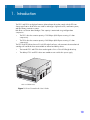
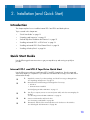
1. Introduction
The LTO-1 and LTO-2 are high-performance 8-channel tape drives that comply with the LTO interchange specifications. Both drives are suited for mid-range to high-end servers, mainframe systems,
and tape library automation systems.
Both drives use Ultrium data cartridges. Their capacity is maximized using intelligent data
compression.
•
The LTO-1 drive has a native capacity of 100 Gbytes (200 Gbytes assuming 2:1 data
compression).
•
The LTO-2 drive has a native capacity of 200 Gbytes (400 Gbytes assuming 2:1 data
compression).
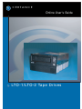
The LTO-1 and LTO-2 drives have a 5¼ inch full height form factor, with automatic electromechanical
cartridge soft load. Both drives are available as internal and desktop drives.
•
The internal LTO-1 and LTO-2 drives are designed to fit in a 5¼-inch full-height drive bay.
•
The desktop LTO-1 and LTO-2 drives are standalone units with built-in power supply.
LTO-1 and LTO-2 Drives
Figure 1. Drives Covered in this User’s Guide
10
Introduction
Features
Features
The following list summarizes the key features of the LTO-1 and LTO-2 drives.
•
Performance
•
LTO-1: Up to 16 Mbytes-per-second native transfer.
•
LTO-2: Up to 34 Mbytes--per-second native transfer.
•
FastSense™ — optimizes data transfers, resulting in shorter backup times and increased
reliability.
•
Two convenient form-factors:
•
5¼-inch internal form-factor for installation in a 5¼-inch half-height space.
•
External desktop form-factor.
•
Intelligent data compression maximizes performance and capacity by analyzing
compressibility prior to recording.
•
SCSI and Fibre Channel interfaces.
•
Cartridge memory enables fast loading of cartridges and stores pertinent information about
the media.
•
64-Mbyte data buffer for extra fast backups on high-performance systems.
•
Tape Alert drive performance monitoring and reporting.
•
3rd generation read channel for increased maturity and data integrity.
•
Patented head positioner for increased data integrity.
•
Shock dampened isolated chassis.
•
Managed airflow dynamics with isolated HTI chamber.
•
Two levels of ECC for extra data safety and protection from errors.
•
Reliable tape picking implementation for increased reliability.
•
Custom-designed LSI circuitry for fast, efficient data processing.
•
RISC processors for fast, efficient data processing.
•
Supports native firmware of a wide variety of UNIX platforms.
•
Remote diagnostics through monitoring and testing capabilities.
•
Support for SCSI-2 and some SCSI-3 instructions.
11
Introduction
Using This Guide
Using This Guide
This User’s Guide describes how to install, configure, and care for the LTO-1 and LTO-2 desktop and
internal tape drives. Please read the appropriate chapters and appendixes carefully, and keep this
Guide handy for future reference.
•
Chapter 1, Introduction provides an overview of LTO and Ultrium technology, and summarizes the drive’s key features.
•
Chapter 2, Installation describes handling precautions, unpacking tips, and installation
instructions for the internal and desktop drives, as well as a summary of cabling and connector specifications. It also provides quick-start instructions for getting the drives up and running
in the shortest possible time.
•
Chapter 3, Operation explains the use and operation of the drive and describes maintenance procedures, including drive “parking.”
•
Chapter 4, Theory describes the theory of operation behind the drives, including the technology used in various drive components.
•
Chapter 5, Specifications contains detailed drive and cartridge specifications, as well as
a summary of regulatory approvals.
•
Chapter 6, Unix Settings describes the settings for Unix systems.
•
Chapter 7, Fibre Channel describes the Fibre Channel settings for the LTO-1 drive.
•
Chapter 8, Troubleshooting Guide provides troubleshooting procedures you can follow
in the unlikely event you encounter a problem with your drive.
12
2. Installation (and Quick Start)
Introduction
This chapter explains how to install the Internal LTO-1 and LTO-2 and desktop drives.
Topics covered in this chapter are:
•
“Quick Start Guide” on page 13
•
“Unpacking and Inspection” on page 15
•
“Internal Tape Drive Guidelines and Cautions” on page 15
•
“Installing an Internal LTO-1 or LTO-2 Drive” on page 16
•
“Installing an Internal LTO-1 Fibre Channel Drive” on page 23
•
“Installing a Desktop Drive” on page 28
Quick Start Guide
Use the following quick-start instructions to get your tape drive up and running as quickly as
possible.
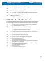
Internal LTO-1 and LTO-2 Tape Drive Quick Start
Use the following procedure to install internal LTO-1 and LTO-2 tape drives. Print this page and
check each step as you complete it. If you need more information about a step, turn to the section
referenced in the step.
❑
1.
Unpack the contents of your drive package, and check for missing or damaged items.
See “Unpacking and Inspection” on page 15.
❑
2.
Review the drive’s default settings and change them if necessary:
• SCSI ID: 6
• Terminator Power: Disabled
See“Configuring an HVD or LVD Drive” on page 17.
❑
3.
Turn off your computer, remove its covers and power cable, and select a mounting bay for
the drive.
See “Mounting an Internal HVD or LVD Drive” on page 19.
❑
4.
Connect a SCSI interface cable to the drive.
See “Connecting a SCSI Cable” on page 20.
❑
5.
Terminate the SCSI bus if the internal tape drive is the last device on the SCSI bus.
See “Checking the SCSI Termination” on page 20.
13
Installation (and Quick Start)
Quick Start Guide
❑
6.
Connect a serial cable, if connecting the tape drive to a tape library.
See “Connecting a Serial Cable for Tape Libraries” on page 21.
❑
7.
Connect a power cable to the drive.
See “Connecting a Power Cable” on page 22.
❑
8.
Replace the computer covers and power cable, turn on the computer, and verify that the
internal tape drive is operating properly.
❑
9.
If you intend to use your drive with Microsoft Windows Server 2003, Windows XP, or
Windows 2000, install the appropriate LTO driver.
See “Installing the LTO Driver” on page 22.
❑
10. Register your tape drive.
See “Registering Your Tape Drive” on page 22.
Internal LTO-1 Fibre Channel Tape Drive Quick Start
Use the following procedure to install an internal LTO-1 Fibre Channel tape drive. Print this page and
check each step as you complete it. If you need more information about a step, turn to the section
referenced in the step.
❑
1.
Unpack the contents of your drive package, and check for missing or damaged items.
See “Unpacking and Inspection” on page 15.
❑
2.
Review the drive’s default settings and change them if necessary:
•
Loop ID: 0000000
See“Configuring the Internal Fibre Channel Drive” on page 23.
❑
3.
Turn off your computer, remove its covers and power cable, and select a mounting bay for
the drive.
See “Mounting the Internal FC Drive” on page 24.
❑
4.
Connect a Fibre Channel LC interface cable to the drive.
See “Connecting a Fibre Channel Cable” on page 25.
❑
5.
Connect a serial cable, if connecting the tape drive to a tape library.
See “Connecting a Serial Cable for Tape Libraries” on page 26.
❑
6.
Connect a power cable to the drive.
See “Connecting a Power Cable” on page 27.
❑
7.
Replace the computer covers and power cable, turn on the computer, and verify that the
internal tape drive is operating properly.
❑
8.
If you intend to use your drive with Microsoft Windows Server 2003, Windows XP, or
Windows 2000, install the appropriate LTO driver.
See “Installing the LTO Driver” on page 27.
❑
9.
Register your tape drive.
See “Registering Your Tape Drive” on page 27.
14
Installation (and Quick Start)
Unpacking and Inspection
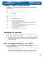
Desktop LTO-1 and LTO-2 Tape Drive Quick Start
Use the following procedure to install desktop LTO-1 and LTO-2 tape drives. Print this page and
check each step as you complete it. If you need more information about a step, turn to the section
referenced in the step.
❑
1.
Unpack the contents of your drive package, and check for missing or damaged items.
See “Unpacking and Inspection” on page 15.
❑
2.
Review the drive’s default settings and change them if necessary:
•
SCSI ID: 6
See“Setting the SCSI ID” on page 28.
❑
3.
Connect a SCSI interface cable to the drive.
See “Connecting a SCSI Cable” on page 29.
❑
4.
Check the SCSI termination.
See “Checking the SCSI Termination” on page 29.
❑
5.
Connect a power cable to the drive.
See “Connecting a Power Cord” on page 30.
❑
6.
Turn on the computer, turn on the desktop tape drive, and verify that the desktop tape
drive is operating properly.
❑
7.
If you intend to use your drive with Microsoft Windows Server 2003, Windows XP, or
Windows 2000, install the appropriate LTO driver.
See “Installing the LTO Driver” on page 30.
❑
8.
Register your tape drive.
See “Registering Your Tape Drive” on page 30.
Unpacking and Inspection
Although drives are inspected and carefully packaged at the factory, damage may occur during
shipping. Follow these steps for unpacking the drive.
1.
Visually inspect the shipping containers and notify your carrier immediately of any damage.
2.
Place shipping containers on a flat, clean, stable surface; then carefully remove and verify the
contents against the packing list. If parts are missing or the equipment is damaged, notify your
Certance representative.
3.
Always save the containers and packing materials for any future reshipment.
Internal Tape Drive Guidelines and Cautions
The following guidelines and cautions apply to handling and installing internal tape drives. Keep
them in mind as you install the drive.
•
Handle the drive by the sides rather than by the top cover to reduce the risk of dropping the
drive or damaging it during installation.
•
Internal drives contain some exposed components that are sensitive to static electricity. To
reduce the possibility of damage from static discharge, the drives are shipped in a protective
antistatic bag. Do not remove the drive from the antistatic bag until you are ready to install it.
15
Installation (and Quick Start)
Drive Installation Instructions
•
Before you remove the drive from the antistatic bag, touch a metal or grounded surface to discharge any static electricity buildup from your body.
•
Always lay the drive either on top of the antistatic bag or place it inside of the bag to reduce
the chance of damage from static discharge.
•
Install HVD drives only in an HVD environment, Fibre Channel drives only in a Fibre Channel
environment, and LVD drives only in an LVD environment. Do not mix HVD and LVD devices on
the same SCSI bus. Look at the label above the drive’s SCSI connector to determine whether
the drive is an HVD or an LVD model (see Figure 2 on page 16):
SCSI
LVD/SE
LVD label
SCSI
DIFF
Fibre Channel
HVD label
Figure 2. Connector Labels
•
Due to the speed of the LTO-2 drive, it is recommended that a maximum of one LTO-2 drive be
connected to one host SCSI adapter. In a switched Fibre Channel environment, the maximum
number of drives that can be used simultaneously depends on the bandwidth of the loop.
Drive Installation Instructions
After unpacking and inspecting your shipping containers and reviewing the installation guidelines
and cautions, proceed to the appropriate section in this chapter for instructions on installing your
LTO-1 or LTO-2 tape drive.
•
If you have an internal LTO-1 or LTO-2 tape drive, go to “Installing an Internal LTO-1 or LTO-2
Drive” on page 16.
•
If you have an internal LTO-1 Fibre Channel tape drive, go to “Installing an Internal LTO-1
Fibre Channel Drive” on page 23.
•
If you have a desktop LTO-1 or LTO-2 tape drive, go to “Installing a Desktop Drive” on
page 28.
Installing an Internal LTO-1 or LTO-2 Drive
Installing an internal LTO-1 or LTO-2 tape drive with an Ultra2 SCSI LVD or Ultra SCSI HVD interface
involves the following steps:
1.
“Configuring an HVD or LVD Drive” on page 17
2.
“Mounting an Internal HVD or LVD Drive” on page 19
3.
“Connecting a SCSI Cable” on page 20
4.
“Checking the SCSI Termination” on page 20
5.
“Connecting a Serial Cable for Tape Libraries” on page 21
6.
“Connecting a Power Cable” on page 22
7.
“Registering Your Tape Drive” on page 22
If you have a Fibre Channel drive, refer to “Installing an Internal LTO-1 Fibre Channel Drive” on
page 23.
16
Installation (and Quick Start)
Installing an Internal LTO-1 or LTO-2 Drive
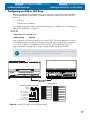
Configuring an HVD or LVD Drive
Before you install the HVD or LVD tape drive in your computer, you may need to configure the drive’s
SCSI ID and terminator power features. The default configuration settings for the LTO-1 and LTO-2
drives are:
•
SCSI ID: 6
•
Terminator power: disabled
If you need to change these settings, refer to the following sections. Otherwise, skip to “Mounting an
Internal HVD or LVD Drive” on page 19.
SCSI ID
Jumper Pins: 1–2, 3–4, 5–6, 7–8
Default Setting:
SCSI ID 6
Each SCSI device on the bus must have its own unique SCSI ID. The internal tape drive is shipped
with a default SCSI ID of 6. If another SCSI device in the SCSI chain is using this ID, use jumper pins
1–2, 3–4, 5–6, and 7–8 to change the SCSI ID of the LTO-1 or LTO-2 drive (see Figure 3 on
page 17 and Table 1 on page 18), or assign a unique SCSI ID to the other SCSI device.
NOTE: The SCSI controller or host adapter generally uses ID 7. In some systems, the boot drive
uses ID 0 or ID 1. Avoid setting your drive’s SCSI ID to these settings.
Jumper Settings:
Drive-configuration jumper pins
Default
settings:
Pins: Function:
1-2 SCSI ID bit 0
3-4 SCSI ID bit 1
5-6 SCSI ID bit 2
7-8 SCSI ID bit 3
9-10 Reserved
11-12 Termination Power
SCSI ID=0
SCSI ID=8
SCSI ID=1
SCSI ID=9
SCSI ID=2
SCSI ID=10
SCSI ID=3
SCSI ID=11
SCSI ID=4
SCSI ID=12
SCSI ID=5
SCSI ID=13
SCSI ID=6
SCSI ID=14
SCSI ID=7
SCSI ID=15
Term. power
Figure 3. Internal LTO-1 and LTO-2 Drive Jumper Settings
17
Installation (and Quick Start)
Installing an Internal LTO-1 or LTO-2 Drive
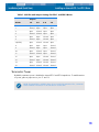
Table 1. SCSI IDs and Jumper Settings for LTO-1 and LTO-2 Drives
Jumpers
SCSI ID
1–2
3–4
5–6
7–8
0
Open
Open
Open
Open
1
Shunted
Open
Open
Open
2
Open
Shunted
Open
Open
3
Shunted
Shunted
Open
Open
4
Open
Open
Shunted
Open
5
Shunted
Open
Shunted
Open
6 (default)
Open
Shunted
Shunted
Open
8
Open
Open
Open
Shunted
9
Shunted
Open
Open
Shunted
10
Open
Shunted
Open
Shunted
11
Shunted
Shunted
Open
Shunted
12
Open
Open
Shunted
Shunted
13
Shunted
Open
Shunted
Shunted
14
Open
Shunted
Shunted
Shunted
15
Shunted
Shunted
Shunted
Shunted
Terminator Power
By default, terminator power is disabled on internal LTO-1 and LTO-2 tape drives. To enable terminator power, place a jumper across pins 11 and 12.
NOTE: The internal LTO-1 and LTO-2 drives do not provide SCSI termination. Thus, a terminator
must be installed on the drive if it is the last device in a SCSI chain.
18
Installation (and Quick Start)
Installing an Internal LTO-1 or LTO-2 Drive
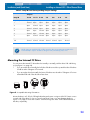
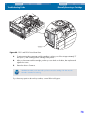
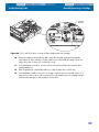
Mounting an Internal HVD or LVD Drive
You can mount the internal LTO-1 and LTO-2 drives either horizontally or vertically, with the drives left
side facing up (see Figure 4 on page 19).
•
If you mount the drive vertically, the left side of the drive must face up and the side of the drive
should be within 5 degrees of horizontal.
•
If you mount the drive horizontally, the base of the drive must be within 15 degrees of horizontal and the PCB side of the drive must face down.
Figure 4. Acceptable Mounting Orientations
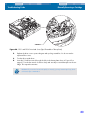
Mount the drive in a 5.25-inch, full-height drive bay and secure it using two M3.0 X 5 metric screws
on each side of the drive. Do not use screws longer than 5 mm or you may damage the drive.
Figure 5 on page 19 shows the locations of the mounting-screw holes on the side and bottom of the
drive, respectively.
Figure 5. Internal LTO-1 and LTO-2 Drive Mounting Dimensions
19
Installation (and Quick Start)
Installing an Internal LTO-1 or LTO-2 Drive
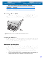
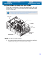
Connecting a SCSI Cable
The internal LTO-1 and LTO-2 drives have an Ultra2 SCSI interface, terminated by either a 68-pin
HVD or LVD SCSI connector. Use the following procedure to connect a SCSI cable to this connector.
1.
Turn off all power to the drive and the computer.
2.
Attach the SCSI interface cable to the 68-pin SCSI interface connector on the back of the drive
(see Figure 6 on page 20).
8
Figure 6. Rear View of the Internal LTO-1 (left) and LTO-2 (right) Drives
CAUTION: Install an HVD drive only in an HVD environment and an LVD drive only in an LVD
environment. Look at the label above the drive’s SCSI connector to determine if the drive is an
HVD or an LVD model (see Figure 2 on page 16). Plugging an HVD drive into an LVD bus, or
vice versa, makes the entire bus non-functional and may permanently damage the drive or other
SCSI devices on the bus.
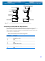
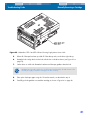
Checking the SCSI Termination
By default, the Internal LTO-1 and LTO-2 drives do not provide SCSI termination. If you use this
default setting, you must place a SCSI bus terminator or a SCSI device with termination enabled at
the end of the SCSI chain. Two examples of SCSI termination are shown in Figure 7 on page 21.
The Internal LTO-1 and LTO-2 drives will provide terminator power if a jumper is placed on the termination power jumper pins (see “Terminator Power” on page 18).
20
Installation (and Quick Start)
Installing an Internal LTO-1 or LTO-2 Drive
SCSI Terminator
Tape drive
(no
termination)
SCSI device
(termination
enabled)
Tape drive
(no
termination)
SCSI device
(termination
disabled)
SCSI Controller
SCSI Controller
(termination enabled)
(termination enabled)
Figure 7. Two SCSI Termination Examples for the Internal LTO-1 and LTO-2 Drives
Connecting a Serial Cable for Tape Libraries
The Internal LTO-1 and LTO-2 drives include an RS-422 serial interface for tape libraries. This connector is located on the lower left side of the back of the drive (see Figure 6 on page 20).
Table 2 on page 21 shows the pin descriptions for the serial interface connector. The pins on this
connector are set on 2-millimeter centers.
Table 2. Serial Interface Connector Pin Assignments
Pin Numbers
Description
1 through 8
Reserved (do not use)
9
Lib RXD-P (input to drive)
10
GND
11
Lib RXD-N (input to drive)
12
GND
13
Lib TXD-P (output from drive)
14
GND
15
Lib TXD-N (output from drive)
16
GND
21
Installation (and Quick Start)
Installing an Internal LTO-1 or LTO-2 Drive
Connecting a Power Cable
Attach a four-pin power cable to the power connector on the back of the drive. Figure 6 on page 20
shows the location of the power connector.
The recommended 4-pin power connector for internal drives is an AMP 1-48024-0 housing with
AMP 60617-1 pins or equivalent.
Installing the LTO Driver
If you intend to use your drive with the Microsoft native backup applet on Windows Server 2003,
Windows XP, or Microsoft Windows 2000 operating system, install the appropriate LTO driver. See
the Tape Resource CD. This driver is not necessary with commercial backup application software.
Registering Your Tape Drive
After you install the internal tape drive, be sure to register it. Registering your drive ensures that you
will receive the latest information about your drive, as well as other product, service, and support
information. For your convenience, you can register your drive either through our Web site or by
fax.
•
If you have an Internet connection, please visit www.certance.com and select “Product
Registration” from the “Products” menu.
•
If you do not have an Internet connection, complete the Registration Card included with your
package and either mail or fax it to the address or fax number on the Card.
22
Installation (and Quick Start)
Installing an Internal LTO-1 Fibre Channel Drive
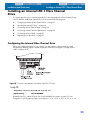
Installing an Internal LTO-1 Fibre Channel
Drive
This section describes how to install an internal LTO-1 drive equipped with a Fibre Channel LC Optical (FC) interface. Installing an internal LTO-1 FC drive involves the following steps:
1.
“Configuring the Internal Fibre Channel Drive” on page 23
2.
“Mounting the Internal FC Drive” on page 24
3.
“Connecting a Fibre Channel Cable” on page 25
4.
“Connecting a Serial Cable for Tape Libraries” on page 26
5.
“Connecting a Power Cable” on page 27
6.
“Registering Your Tape Drive” on page 27
Configuring the Internal Fibre Channel Drive
Before you install the tape drive in your computer, you may need to configure the drive’s hardassigned loop identifier. Jumpers located on the back of the drive (see Figure 8 on page 23) are
used to configure the ID.
Figure 8. Connectors and Jumpers on the Back of the LTO-1 FC Drive
Loop ID
Jumper Pins: 13–14, 11–12, 9–10, 7–8, 5–6, 3–4, 1–2
Default Setting:
Loop ID 0000000
By default, the LTO-1 internal FC drive uses Loop ID 0000000 (no jumpers in place). You can
change this Loop ID by placing jumpers on jumper pins 13–14, 11–12, 9–10, 7–8, 5–6, 3–4, 1–2.
23
Installation (and Quick Start)
Installing an Internal LTO-1 Fibre Channel Drive
Table 3. Loop IDs and Corresponding Jumper Settings
Jumpers
Loop ID
13–14
11–12
9–10
7–8
5–6
3–4
1–2
0 (default)
Open
Open
Open
Open
Open
Open
Open
1
Shunted
Open
Open
Open
Open
Open
Open
2
Open
Shunted
Open
Open
Open
Open
Open
3
Shunted
Shunted
Open
Open
Open
Open
Open
4
Open
Open
Shunted
Open
Open
Open
Open
5
Shunted
Open
Shunted
Open
Open
Open
Open
6
Open
Shunted
Shunted
Open
Open
Open
Open
Shunted
Shunted
Shunted
Shunted
Shunted
Open
Shunted
...
125
NOTE: Setting an invalid ID (7Fh or 7Eh) causes the drive not to participate in LIHA and to
instead attempt to acquire an address during the LISA (soft address) phase of LIP.
Mounting the Internal FC Drive
You can mount the internal FC drive either horizontally or vertically, with the drive’s left side facing
up (see Figure 9 on page 24).
•
If you mount the drive vertically, the left side of the drive must face up and the side of the drive
should be within 5 degrees of horizontal.
•
If you mount the drive horizontally, the base of the drive must be within 15 degrees of horizontal and the PCB side of the drive must face down.
Figure 9. Acceptable Mounting Orientations
Mount the drive in a 5.25-inch, full-height drive bay and secure it using two M3.0 X 5 metric screws
on each side of the drive. Do not use screws longer than 5 mm or you may damage the drive.
Figure 10 on page 25 shows the locations of the mounting-screw holes on the side and bottom of
the drive, respectively.
24
Installation (and Quick Start)
Installing an Internal LTO-1 Fibre Channel Drive
Figure 10. Internal LTO-1 FC Drive Mounting Dimensions
Connecting a Fibre Channel Cable
The internal LTO-1 FC drive has two FC connectors that can connect to either a hub or a switch. In
systems that support failover, both FC connectors can be used to allow hosts to maintain a connection with the drive if one connection fails. The internal LTO-1 FC drive is 100-M5-SN-I compliant and
uses LC style connectors. Either 50 or 62.5µm multimode optical fiber cables can be used.
1.
Turn off all power to the drive and the computer.
2.
Attach the interface cable to either of the two LC optical interface connectors on the back of
the drive (labeled A and B in Figure 11 on page 26).
3.
In systems that support “failover,” connect the other port through separate loops or fabrics to
the same set of host computers. This way, if one connection fails, the other can be used to continue the data transfer.
25
Installation (and Quick Start)
Installing an Internal LTO-1 Fibre Channel Drive
Figure 11. FC Optical Connectors on the Back of the Internal LTO-1 FC Drive
Connecting a Serial Cable for Tape Libraries
The Internal LTO-1 FC drive includes an RS-422 serial interface for tape libraries. This connector is
located on the lower left side of the back of the drive (see Figure 12 on page 26).
Table 4 on page 26 shows the pin descriptions for the serial interface connector. The pins on this
connector are set on 2-millimeter centers. The drive uses pin 1 to detect the presence of a tape
library. The serial interface cable must connect this pin to the adjacent pin 3.
17 15 13 11 9 7
5
3
1
18 16 14 12 10 8
6
4
2
Figure 12. FC Serial Connector on the Back of the Internal LTO-1 FC Drive
Table 4. Serial Interface Connector Pin Assignments
Pin Numbers
Description
1
Library detect (cable should connect pin 1 to pin 3)
2
Lib TXn (output from drive, transmit negative)
3
GND
4
Lib TXp (output from drive, transmit positive)
5
GND
6
Lib RXn (input to drive, receive negative)
7
GND
26
Installation (and Quick Start)
Installing an Internal LTO-1 Fibre Channel Drive
Table 4. Serial Interface Connector Pin Assignments (Continued)
Pin Numbers
Description
8
Lib RXp (input to drive, receive positive)
9 through 18
Reserved (do not use)
Connecting a Power Cable
Attach a four-pin power cable to the power connector on the back of the drive. Figure 13 on
page 27 shows the location of the power connector on internal LTO-1 FC drive. The recommended
4-pin power connector is an AMP 1-48024-0 housing, with AMP 60617-1 pins or equivalent.
Figure 13. Power Connector on the Back of the Internal LTO-1 FC Drive
Installing the LTO Driver
If you intend to use your drive with the Microsoft Windows Server 2003, Windows XP, or Microsoft
Windows 2000 operating system, install the LTO-1 FC driver. See the Tape Resource CD. This driver
is not necessary with commercial backup application software.
Registering Your Tape Drive
After you install the internal FC tape drive, be sure to register it. Registering your drive ensures that
you will receive the latest information about your drive, as well as other product, service, and support information. For your convenience, you can register your drive either through our Web site or
by fax.
•
If you have an Internet connection, please visit www.certance.com and select “Product
Registration” from the “Products” menu.
•
If you do not have an Internet connection, complete the Registration Card included with your
package and either mail or fax it to the address or fax number on the Card.
27
Installation (and Quick Start)
Installing a Desktop Drive
Installing a Desktop Drive
The desktop LTO-1 and LTO-2 tape drives) are compact subsystems that connect to the host computer
through a SCSI port. Installing a desktop drive involves the following steps:
1.
“Setting the SCSI ID” on page 28
2.
“Connecting a SCSI Cable” on page 29
3.
“Checking the SCSI Termination” on page 29
4.
“Connecting a Power Cord” on page 30
5.
“Registering Your Tape Drive” on page 30
Setting the SCSI ID
Each SCSI device on the bus must have its own unique SCSI ID. The desktop tape drive is shipped
with a default SCSI ID of 6. Avoid setting drive ID to 7. If another SCSI device in the SCSI chain is
already using this ID, either use the push-button switch on the back of the drive to change the drive’s
SCSI ID (see Figure 14 on page 28) or assign a unique SCSI ID to the other SCSI device.
If you change the SCSI ID on the tape drive, turn off the tape drive before changing the SCSI ID. The
change takes effect when you turn on the drive.
NOTE: The SCSI controller or host adapter generally uses ID 7. In some systems, the boot drive
uses ID 0 or ID 1. Avoid setting your drive’s SCSI ID to these settings.
+
–
Figure 14. Switches and Connectors on the Back of Desktop LTO-1 and LTO-2 Drives
28
Installation (and Quick Start)
Installing a Desktop Drive
Connecting a SCSI Cable
The desktop LTO-1 and LTO-2 drives have two 68-pin, shielded SCSI interface connectors (ANSI
Alternative 2) on the rear panel (see Figure 14 on page 28). These connectors consist of two rows of
ribbon contacts spaced 2.16 mm (0.085 in) apart. Either connector can be used as a SCSI IN or
SCSI OUT connection. This means you can use either connector to attach the drive to a host computer or to another SCSI device.
1.
Turn off all power to the drive and the computer.
2.
Attach the SCSI interface cable to one of the 68-pin SCSI interface connectors on the back of
the drive (see Figure 14 on page 28).
Checking the SCSI Termination
If the desktop LTO-1 or LTO-2 drive is the last or only device in a SCSI chain, install a terminating
plug on the unused SCSI connector. See Figure 15 on page 29 for two SCSI termination examples.
You can purchase appropriate terminating plugs on the Internet at http://shop.certance.com (U.S.
only).
NOTE: Termination power is enabled as a default for desktop drives.
External
SCSI device
SCSI Terminators
External
Tape Drive
External
Tape Drive
External
SCSI device
SCSI Controller
(termination disabled)
SCSI Controller
(termination enabled)
Example 1: SCSI termination
in a system that has only
external SCSI devices.
Internal
SCSI device
(termination
enabled)
Example 2: SCSI termination
in a system that has both
internal and external SCSI
devices.
Figure 15. SCSI Termination Examples for the Desktop LTO-1 and LTO-2 Tape Drives
29
Installation (and Quick Start)
Installing a Desktop Drive
Connecting a Power Cord
Attach the power cord securely to the power connector on the back of the desktop LTO-1 or LTO-2
drive (see Figure 14 on page 28).
Installing the LTO Driver
If you intend to use your drive with either the Microsoft Windows Server 2003, Windows XP, or
Microsoft Windows 2000 operating system, install the LTO driver. See the Tape Resource CD. This
driver is not necessary with commercial backup application software.
Registering Your Tape Drive
After you install the desktop tape drive, be sure to register it. Registering your drive ensures that you
will receive the latest information about your drive, as well as other product, service, and support
information. For your convenience, you can register your drive either through our Web site or by
fax.
•
If you have an Internet connection, please visit www.certance.com and select “Product
Registration” from the “Products” menu.
•
If you do not have an Internet connection, complete the Registration Card included with your
package and either mail or fax it to the address or fax number on the Card.
30
3. Operation
This chapter describes how to operate the LTO-1 and LTO-2 drives.
Topics covered in this chapter are:
•
“Understanding the Front Panel Display” on page 31
•
“Blink Codes” on page 32
•
“Using LTO Cartridges” on page 34
•
“Drive Maintenance” on page 36
•
“Parking the Drive for Shipping” on page 37
•
“Emergency Reset and Emergency Cartridge Eject” on page 75
•
“Manually Removing a Cartridge” on page 76
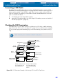
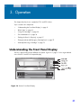
Understanding the Front Panel Display
The LTO-1 and LTO-2 drives have different front panels. Figure 16 on page 31 shows a generalized
view of the LTO-1 and LTO-2 front-panel display.
Figure 16. Generic Front Panel Display
31
Operation
Blink Codes
All drives have four LEDs on the front panel. The LED colors and functions are summarized below.
•
Power LED (green)
•
LTO-2 only: Blinks during drive power-up and Power-on Self Test (POST).
•
Remains on during normal operation.
•
Remains on along with the Status light If there is an error during the POST.
•
Status LED (amber)
•
Error LED (orange)
•
Drive LED (green)
The Status, Error, and Drive LEDs blink or go on to indicate information about the tape drive. For
more information about the “blink codes” associated with these LEDs, refer to “Blink Codes” on
page 32.
Blink Codes
Table 5 on page 32 summarizes the blink codes for the LTO-1 tape drives. Table 6 on page 33 summarizes the blink codes for the LTO-2 tape drives.
Table 5. LTO-1 Tape Drive Blink Codes
Drive Condition
Status LED (Amber)
Cleaning Request
ON
Write-protected
1/2 sec ON
1/2 sec OFF
Prevent media removal mode
active
1/2 sec ON
1/8 sec OFF
Hardware or firmware error
Error LED (Orange)
Drive LED (Green)
1/8 sec ON
1/8 sec OFF
Positioning – loading, unloading,
rewinding, spacing, or locating
ON continuously
Tape Active – writing, reading,
or verifying
1/2 sec ON
1/8 sec OFF
SCSI active
1/4 sec ON
1/8 sec OFF
Manual intervention required
1/8 sec ON
1/8 sec OFF
1/8 sec ON
1/8 sec OFF
Power On Self Test (POST) failure ON
1/2 sec ON
1/2 sec OFF
Excessive rewrites or read C2
errors
1/4 sec ON
1/4 sec OFF
1/8 sec ON
1/8 sec OFF
Cleaning cartridge present
ON
ON
Cleaning cartridge at EOT
1/8 sec ON
1/8 sec OFF
ON
32
Operation
Blink Codes
Table 5. LTO-1 Tape Drive Blink Codes (Continued)
Drive Condition
Status LED (Amber)
Error LED (Orange)
Drive LED (Green)
SCSI bus reset
1/4 sec ON
1/8 sec OFF
1/4 sec ON
1/8 sec OFF
Servo initialization
1/2 sec ON
1/2 sec OFF
1/2 sec ON
1/2 sec OFF
Power On Self Test (POST) in
progress
1/4 sec ON
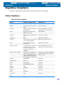
1/4 sec OFF
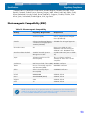
1/4 sec ON
1/4 sec OFF
1/4 sec ON
1/4 sec OFF
Cleaning failure
1/8 sec ON
1/8 sec OFF
1/8 sec ON
1/8 sec OFF
ON
Microcode download
1/8 sec ON
1/8 sec OFF
1/4 sec ON
1/4 sec OFF
1/8 sec ON
1/8 sec OFF
Microcode download error
1/8 sec ON
1/8 sec OFF
1/8 sec ON
1/8 sec OFF
1/8 sec ON
1/8 sec OFF
Table 6. LTO-2 Tape Drive Blink Codes
Drive Condition
Status LED (Amber) Error LED (Orange)
Cleaning Request
ON
Hardware error
Drive LED (Green)
Fast
Positioning – loading, unloading,
rewinding, spacing, or locating
Slow
Tape Active – writing, reading, or
verifying
Slow
Manual intervention required
ON
Power On Self Test (POST) failure
ON
Fast
Cleaning cartridge present
ON
ON
Cleaning cartridge at EOT
Fast
ON
Servo initialization
Slow
Slow
Power On Self Test (POST) in
progress
Slow
Slow
Cleaning failure or media error
Fast
Fast
Microcode download
Fast
Slow
Fast
Microcode download error
Fast
Fast
Fast
Slow
NOTE: In Table 6 on page 33, ON refers to a constant light; slow refers to a blink rate of 1/2
second on, 1/2 second off; and fast refers to a blink rate of 1/8 second on, 1/8 second off.
33
Operation
Using LTO Cartridges
Using LTO Cartridges
Loading a Cartridge
To load an Ultrium cartridge into LTO-1 and LTO-2 drives, place the cartridge in the slot and then
gently push it. Then:
•
Continue to push the cartridge the rest of the way into the drive; or,
•
Press the load/unload button on the front of the drive to seat the cartridge; or,
•
Use a library or host command to finish loading the tape.
Unloading a Cartridge
To unload an Ultrium cartridge from LTO-1 and LTO-2 drives, either:
•
Use a library or host command to unload the tape, or
•
Push the load/unload button on the front of the drive.
CAUTION: Several seconds may elapse between the time you press the load/unload button and
the time the cartridge is ejected. Do not power down the tape drive or the host computer until the
drive has completely ejected the cartridge.
34
Operation
Using LTO Cartridges
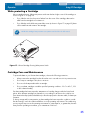
Write-protecting a Cartridge
Ultrium cartridges have a sliding write-protect switch near the back right corner of the cartridge, as
shown in Figure 17 on page 35.
•
If you slide the switch to the position farthest from the corner of the cartridge, data can be
read from the cartridge but not written to it.
•
If you slide the switch all the way toward the corner (as shown in Figure 17 on page 35), data
can be read from and written to the cartridge.
NOTE: LTO cartridges have prewritten servo patterns and should not be bulk erased.
Figure 17. Ultrium Cartridge Showing Write-protect Switch
Cartridge Care and Maintenance
To protect the data on your Ultrium data cartridges, observe the following precautions:
•
Always remove the cartridge from the drive when not in use and store it in its protective case.
•
Do not expose cartridges to dirt, dust or moisture.
•
Do not touch the tape media within a cartridge.
•
Do not use data cartridges outside the specified operating conditions: 10o C to 45o C, 10%
to 80% relative humidity.
If a data cartridge has been exposed to temperature or humidity changes within the limits listed
above, allow the tape cartridge to acclimate to its surroundings for at least one hour before use.
Then retention the tape (as described below) to allow the tape pack to become stable, for better performance.
If, during storage and/or transportation, a data cartridge has been exposed to conditions outside
the above range, it must be conditioned before use in the operating environment. The conditioning
process requires exposure to the operating environment for a time equal to, or greater than, the time
away from the operating environment, up to a maximum of 24 hours.
35
Operation
Drive Maintenance
•
Keep the cartridge away from direct sunlight and heat sources, such as radiators, heaters or
warm air ducts.
•
Keep the cartridge away from sources of electromagnetic fields, such as telephones, computer
monitors, dictation equipment, mechanical or printing calculators, motors, magnetic tools, and
bulk erasers.
•
Avoid dropping the cartridges. This can damage components inside the cartridge, possibly
rendering the tape unusable. If a tape is dropped it is advisable to open the cartridge door
and make sure that the leader pin is in the correct position. A dropped cartridge should be
retensioned before use.
•
Do not bulk erase Ultrium cartridges. Bulk-erased cartridges cannot be reformatted by the tape
drive and will be rendered unusable.
Drive Maintenance
The Ultrium drive requires little or no maintenance. However, on rare occasions, the drive mechanism may need to be cleaned.
Cleaning the Tape Drive
Excessive tape debris or other material may accumulate on the tape heads if the drive is used with
non-approved media or operated in a hot, dusty environment. In this case, the drive may experience
excessive errors while reading or writing, and the amber Status LED remains on continuously during
operation. This means that the drive heads need to be cleaned.
The LTO cleaning cartridge has the same dimensions as the data cartridge and contains an LTO-CM
(Cartridge Memory), but is loaded with cleaning media instead of recording media. Always keep
the cleaning cartridge in its protective case when not in use.
To clean the drive, insert a Certance-approved cleaning cartridge. During the cleaning process, both
the Status and Drive LEDs remain lit. After the cleaning process is completed, the cartridge may be
ejected automatically, or you may need to press the load/unload button to remove the cartridge.
Each time you use the cleaning cartridge, write the date on the label for future reference.
NOTE: If the Status LED comes on continuously within 24 hours after a cleaning cycle, perform
the cleaning cycle again. If, after three cleaning cycles in a 72-hour period, the Status LED lights
up again, contact Technical Support.
Each time the drive is cleaned, the tape advances to a new, unused section of media. After approximately 50 cleanings, all of the media will be used up and you should discard the cleaning cartridge.
When a cleaning cartridge is used up, the amber Status LED flashes, while the green Drive LED
remains on. Do not reuse a spent cleaning cartridge
NOTE: The cleaning procedure will not run and the cleaning cartridge will be ejected in the following circumstances:
• The drive does not recognize the cartridge as an LTO cleaning cartridge.
• All of the tape on the cleaning cartridge has been used up (at EOT). In this case, the Status
LED will flash rapidly while the Drive LED remains on.
36
Operation
Parking the Drive for Shipping
Parking the Drive for Shipping
Certance recommends that you “park” LTO-1 and LTO-2 drives before shipping them or placing them
in an environment where they may be subject to physical shock. Parking the drives moves the tape
mechanism to the configuration that is resilient to shock. You can park the LTO-1 and LTO-2 drives
using the Load/Unload button on the front of the drive, or by running special software on your host
system. In either case, the drive must be powered up to enter park mode.
Using the Load/Unload Button to Park the Drive
To park a drive manually, press and hold the load/unload button for 15 seconds or more. After you
release the load/unload button, the green Drive LED lights up and the parking process begins. During the parking process, the picker arm moves into the take-up reel.
When the process is complete, the Drive LED goes off, indicating that the drive has been successfully
parked.
After parking the drive, you can turn off the drive and pack it for shipping. When you turn the drive
on again, it automatically returns to normal operating mode.
If you need to unpark the drive without cycling power, press and hold the load/unload button for
more that 5 seconds, but less than 15 seconds.
Using Software to Park the Drive
You can also park LTO-1 and LTO-2 drives using special software that communicates with the drive
through the drive’s SCSI interface. This utility program TapeRx is available on the Tape Resource CD
and from the technical support section of the Certance Web site, at http://support.certance.com.
This utility software supports many commands, one of which can be used to park the LTO-1 and LTO2 drives.
37
4. Theory
This chapter describes operational theories used in the LTO-1 and LTO-2 drives.
The topics covered in this chapter are:
•
“Track Layout” on page 38
•
“Recording Method” on page 39
•
“Data Buffer” on page 40
•
“Data Integrity” on page 40
•
“Data Compression” on page 42
Track Layout
Figure 18 on page 38 shows the layout of data on an LTO tape.
Figure 18. Layout of tracks on LTO Ultrium tape
38
Theory
Recording Method
LTO-1 Drive
With the LTO-1 drive, there are 384 data tracks on the LTO tape, numbered 0 through 383. Data
track 383 is the track closest to the bottom edge of the tape (the reference edge). The area between
adjacent servo bands is a data band. There are 4 data bands, each of which includes 96 data
tracks. The data bands are numbered 2,0,1,3. Data band 2 is closest to the bottom edge of the
tape.
A track group is a set of tracks that is recorded concurrently. The sets of 12 data tracks in a data
band are data sub bands. There are 8 data sub bands per data band. The data tracks are accessed
in a serpentine manner.
A wrap is a track group recorded in the physical forward or physical reverse direction. The wraps
are recorded in a serpentine fashion starting in data band 0. The tape contains 48 track groups, 24
written in the forward direction and 24 written in the reverse direction. Even-numbered wraps are
recorded in the forward direction (BOT to EOT), and odd-numbered wraps are recorded in the
reverse direction (EOT to BOT).
LTO-2 Drive
With the LTO-2 drive, there are 512 data tracks on the LTO tape, numbered 0 through 511. Data
track 511 is the track closest to the bottom edge of the tape (the reference edge). The area between
adjacent servo bands is a data band. There are 4 data bands, each of which includes 128 data
tracks. The data bands are numbered 2,0,1,3. Data band 2 is closest to the bottom edge of the
tape.
A track group is a set of tracks that is recorded concurrently. The sets of 16 data tracks in a data
band are data sub bands. There are 8 data sub bands per data band. The data tracks are accessed
in a serpentine manner.
A wrap is a track group recorded in the physical forward or physical reverse direction. The wraps
are recorded in a serpentine fashion starting in data band 0. The tape contains 64 track groups, 32
written in the forward direction and 32 written in the reverse direction. Even-numbered wraps are
recorded in the forward direction (BOT to EOT), and odd-numbered wraps are recorded in the
reverse direction (EOT to BOT).
Recording Method
The LTO-1 and LTO-2 drives record data using write-equalized (1,7) Run Length Limited (RLL) code.
RLL (1,7) Data bits are defined as follows:
•
A ONE is represented by a flux transition at the center of a bit-cell.
•
A ZERO is represented by no flux transition in the bit-cell.
39
Theory
Data Buffer
Data Buffer
In their default configuration, both the LTO-1 and LTO-2 drives have a 64-Mbyte buffer. The buffer
controller has a burst transfer rate of 320 Mbytes/sec, and utilizes bank switching to achieve a maximum average bandwidth of nearly 240 Mbytes/sec. The high bandwidth is needed to support lookaside data compression in the case of compressible data being transferred from SCSI at 80 Mbytes/
sec.
Data Integrity
The mechanical and electrical design of the drives ensures that drive performance does not degrade
over a drive’s operating life. Changes in head alignment, head wear, component drift, and other
factors are minimized to ensure that data integrity and interchange capability are not compromised
over the drive's operating life.
The error rate of the LTO-1 and LTO-2 drives is less than 1 hard error in 1017 bits. The drives’ undetectable error rate is 1 in 1027 bits read.
Error-correction Code (ECC)
The use of Cyclic Redundancy Checking (CRC), two-level orthogonal Error Correction Coding (ECC)
provides a very low probability of encountering a hard error. During the read process, ECC correction is performed on the fly without affecting tape streaming.
There are two levels of Error Correction Coding (ECC). These two levels are orthogonal — that is, an
ECC codeword at one level intersects ECC codewords at the other level just once, which means
there will be only one common symbol between them. The two levels are called C1 and C2.
C1 ECC
As data is written to memory from the Data Processing unit, the DMA / ECC interface generates C1
ECC bytes and writes them to memory.
As data is written to tape, the C1 ECC is checked and an interrupt generated if there is an error. The
C1 ECC read from memory is the ECC that is written to tape.
When data is read from tape and stored into memory, C1 ECC is checked.
•
If the C1 ECC is good, that codeword pair’s “Valid” bit is set.
•
Otherwise, a pointer to the invalid Codeword Pair is passed to the C1 ECC correction engine.
•
If the C1 ECC correction engine can correct the error, then the corrected bytes are written to memory, and the Valid bit is set.
•
Otherwise, the Valid bit is left cleared.
As data is read from memory to the Data Processor for decompression, the C1 ECC is again
checked and an interrupt generated if it is not correct.
40
Theory
Data Integrity
C2 ECC
C2 ECC involves three distinct operations:
1.
Encoding: Generating C2 ECC bytes from data bytes (performed by ECC co-processor hardware)
2.
Decoding: Generating ECC syndromes from data and ECC bytes, testing for all-zeroes (performed by ECC co-processor hardware)
3.
Correction: Generating corrected data from syndromes.
The correction depends on the number and types of errors involved:
•
For one known C1 codeword pair in error in a sub-data set (C2 codeword), the operation is
performed by the ECC co-processor hardware.
•
For two or more known C1 codeword pairs in error, the matrix is computed by firmware and
the correction is performed by hardware.
•
For one or more unknown C1 codeword pairs, syndromes are generated by hardware, error
location is computed by firmware, the matrix is computed by firmware and the correction is
performed by hardware.
Servo-tracking Faults
During a write operation, if the servo system detects an error that may result in adjacent data tracks
being over-written, the write operation is aborted. The write operation will not continue until the correct servo tracking is re-established.
41
Theory
Data Compression
Data Compression
Typical data streams of text, graphics, software code, or other forms of data contain repeated information of some sort, whether it is at the text level where you can readily recognize regular repetitions of a single word, or at the binary level where the repetitions are in bits or bytes. Although most
data is unique and random, the binary level data exhibits patterns of various sizes that repeat with
varying degrees of regularity.
Storage efficiency is increased if the redundancies or repetition in the data are removed before the
data is recorded to tape. Data compression technology significantly reduces or eliminates redundancies in data before recording the information to tape. This increases the amount of data that can be
stored on a finite medium and increases the overall storage efficiency of the system.
With data compression, the redundant information in a data stream is identified and represented by
codewords or symbols, which allow the same data to be recorded in a fewer number of bits. These
codewords or symbols point back to the original data string, using fewer characters to represent the
strings. Because these smaller symbols are substituted for the longer strings of data, more data can
be stored in the same physical space.
Some important benefits result from data compression in tape drives:
•
The same amount of information can be stored on a smaller length of tape.
•
More data can be stored on a given length of tape.
•
Performance can more closely parallel to that of high-transfer-rate computers.
•
More information can be transferred in the same time interval.
Data Compression Considerations
In an effective data-compression method, several factors are important:
•
The amount of compression. The amount of compression is measured by the compression
ratio. This ratio compares the amount of uncompressed data to the amount of compressed
data. It is obtained by dividing the size of the uncompressed data by the size of the compressed data)
•
The speed with which data is compressed and decompressed relative to the host transfer rate.
•
The types of data to be compressed.
•
The data integrity of the compressed data.
The amount of compression possible in a data stream depends on factors such as:
•
Data pattern
•
Compression algorithm
•
Pattern repetition length
•
Pattern repetition frequency
•
Object size (block of information to be compressed)
•
Starting pattern chosen
The transfer rate depends on factors such as:
•
Compression ratio
42
Theory
Data Compression
•
Drive buffer size
•
Host computer input/output (I/O) speed
•
Effective disc speeds of the host computer
•
Record lengths that the host computer transmits
Data compression algorithms can be tailored to provide maximum compression for specific types of
data. Because varying types of data are encountered in normal day-to-day operating circumstances,
however, an effective data compression method for a tape drive must serve various data types.
Additionally, the data compression method must adapt to different data types, automatically providing optimum handling for all types of data.
Intelligent Data Compression
The tape’s compressed capacity is maximized through the use of intelligent data compression. The
intelligent data compression hardware determines the compressibility of each record. If the size of
the record is larger after a compression attempt than the native (uncompressed) size, then the record
is written in its native form.
The intelligent data compression utilizes two compression schemes:
•
Scheme-1 is a LZ1 based compression scheme using a history buffer to achieve data compression.
•
Scheme-2 is a pass-through compression scheme designed to pass uncompressible data
through with minimal expansion.
There are three specific requirements for compliance with the LTO specification.
•
First: the output data stream must be decompressible following LTO rules to create the input
sequence of records and File Marks perfectly.
•
Second: an LTO compressed data stream may not contain any of the eight reserved Control
Symbols.
•
Third: while control symbols allow switching to Scheme 2, this should never be used by operational software because this capability is only for diagnostic and testing purposes.
Software data compression should never be used because the LTO-1 and LTO-2 drives' built-in intelligent data compression is much more efficient than software data compression systems.
The LTO-1 and LTO-2 drives use a derivative of ALDC-2 lossless data compression that includes additional control codes for intelligent data compression.
43
5. Specifications
This chapter provides technical specifications for the LTO-1 and LTO-2 drives.
The topics covered in this chapter are:
•
“Physical Specifications” on page 44
•
“Power Specifications” on page 47
•
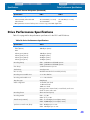
“Drive Performance Specifications” on page 48
•
“Environmental Requirements” on page 49
•
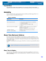
“Reliability” on page 50
•
“Mean Time Between Failures” on page 50
•
“LTO Cartridge Specifications” on page 51
•
“Regulatory Compliance” on page 52
Physical Specifications
Table 7 on page 44 lists the physical specifications of the LTO-1 and LTO-2 drives.
Table 7. LTO-1 and LTO-2 Physical Specifications
Internal SCSI
Drive without
Bezel
Internal Fibre
Channel Drive
without Bezel
Internal SCSI
Drive with Bezel
Desktop SSCI
Drive
Height
3.25 inches
(82.6 mm) max
3.25 inches
(82.6 mm) max
3.32 inches
(84.26 mm)
6.8 inches1
(172.7 mm)
Width
5.75 inches
(146.05 ± 0.25)
5.75 inches
(146.05 ± 0.25 mm)
5.82 inches
(147.75 mm)
7.61 inches
(193.3 mm)
Length
8.06 inches
(205 mm)
10.50 inches
(267 mm) max
8.62 inches
(219 mm) max
12.17 inches2
(309.1 mm)
Weight
6.2 lb.
(2.82 kg)
5.8 lb.
(2.64 kg)
6.5 lb.
(2.95 kg)
14.5 lb.
(6.58 kg)
Specification
1
Includes rubber feet (case alone is 6.44 inches high).
2
Includes front bezel and fan grill (case alone is 11.9 inches long).
44
Specifications
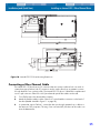
Physical Specifications
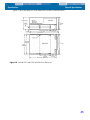
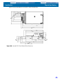
Figure 19 shows the dimensions of the internal LTO-1 and LTO-2 HVD/LVD drives.
Figure 19. Internal LTO-1 and LTO-2 HVD/LVD Drive Dimensions
45
Specifications
Physical Specifications
Figure 20 shows the dimensions of the LTO-1 Fibre Channel drive.
Figure 20. Internal LTO-1 Fibre Channel Drive Dimensions
46
Specifications
Power Specifications
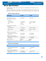
Power Specifications
The desktop LTO-1 and LTO-2 drives come with a built-in 90-260VAC (47-63 Hz) automatic switching power supply.
Maximum voltage and power specifications for the internal LTO-1 and LTO-2 drives are listed in the
tables below. Specifications are the same for SCSI and Fibre Channel drives unless otherwise noted.
Table 8. Voltage and Current
Specification
+12 VDC
+ 5VDC
DC Voltage Tolerance
+ or – 10%
+ or – 5%
Non-operating max voltage
14 Volts peak
7 Volts peak
Ultra2 SCSI LVD;
1.0 amps RMS
3.5 amps max RMS*
Ultra SCSI HVD
1.0 amps RMS
4.0 amps max RMS*
3.0 amps
(1 sec max)
N/A
Ultra2 SCSI LVD;
1.2 amps RMS
4.0 amps max RMS*
Ultra SCSI HVD
1.0 amps RMS
4.0 amps max RMS*
4.0 amps
(1 sec max)
N/A
Ultra2 SCSI LVD; Ultra SCSI HVD
0.5 amps RMS
2.0 amps RMS*
Fibre Channel
0.5 amps RMS
2.5 amps RMS*
Ultra2 SCSI LVD; Ultra SCSI HVD
0.5 amps RMS
1.0 amps RMS*
Fibre Channel
0.5 amps RMS
2.5 amps RMS*
< 100 mV
< 100 mV
Max operating current – LTO-1
Continuous:
Peak:
Max operating current – LTO-2
Continuous:
Peak:
Standby current (max) – LTO-1
Standby current (max) – LTO-2
Ripple (peak-to-peak)
* RMS parameters measured at the power connector using a true RMS digital meter.
Table 9. Power Dissipation
Specification
LTO-1
LTO-2
Ultra2 SCSI LVD; Ultra SCSI HVD
14 watts RMS*
17 watts RMS*
Fibre Channel
19 watts RMS*
N/A
Ultra2 SCSI LVD; Ultra SCSI HVD
30 watts RMS*
31 watts RMS*
Fibre Channel
32.5 watts RMS*
N/A
Max Standby Power
Max Continuous Operating Power
47
Specifications
Drive Performance Specifications
Table 9. Power Dissipation (Continued)
Specification
LTO-1
LTO-2
Ultra2 SCSI LVD; Ultra SCSI HVD
48.5 watts RMS (1 sec max)
65 watts RMS (1 sec max)
Fibre Channel
58.5 watts RMS*
N/A
Max Peak Operating Power
* RMS parameters measured at the power connector using a true RMS digital meter.
Drive Performance Specifications
Table 10 on page 48 lists the performance specifications for the LTO-1 and LTO-2 drives.
Table 10. Drive Performance Specifications
Specification
Value
Capacity
LTO-2 (609 m)
200 Gbytes (native)
LTO-1
Ultrium type A (609 m)
100 Gbytes (native)
Ultrium type B (319 m)
50 Gbytes (native)
Ultrium type C (203 m)
30 Gbytes (native)
Ultrium type D (87 m)
10 Gbytes (native)
Recording density
LTO-1: 3,660 RLL-encoded ONEs per mm
LTO-2: 3,930 RLL-encoded ONEs per mm
Flux density
3,660 flux transitions per mm
Track density
3 tracks per mm
Error recovery
Read-after-write Reed Solomon ECC (2 levels)
Recording unrecoverable errors
<1 in 1017 data bits
Recording undetectable errors
< 1 in 1027 data bits
Tape drive type
LTO (Ultrium)
Head configuration
16 thin-film write heads
16 MR read heads
8 MR servo heads
During operation 8 write heads, 8 read heads, and 2 servo
heads are active at the same
Recording format
Ultrium 8-channel (U-18)
Recording method
LTO-1: (1,7) RLL
LTO-2: 0, 13/11 RLL
Transfer rate (sustained)
LTO-1: 16.137 Mbytes/second (max, native)
LTO-2: 34,000 Mbytes/second (max, native)
Synchronous transfer rate (burst)
LTO-1: 80 Mbytes per sec max
LTO-2: 160 Mbytes per sec max
48
Specifications
Environmental Requirements
Table 10. Drive Performance Specifications
Specification
Value
Asynchronous transfer rate (burst)
40 Mbytes per sec max
Cartridge unload time
3 seconds
Average rewind time (609-m tape)
LTO-1: > 4 seconds
LTO-2: > 5.9 seconds
Maximum rewind time (609-m tape)
LTO-1: <152 seconds
LTO-2: <103 seconds
Average data access time (609-m tape)
from BOW
LTO-1: 76 seconds
LTO-2: 51.5 seconds
Maximum data access time (609-m tape)
from BOW
LTO-1: 152 seconds
LTO-2: 103 seconds
Average rewind time (609-m tape)
< 76 seconds
Tape speed
LTO-1: Up to 4 meters per second
LTO-2: Up to 5.9 meters per second
Environmental Requirements
Table 11 on page 49 lists the environmental specifications for the LTO-1 and LTO-2 drives.
Table 11. Environmental Requirements
Specification
Operational
Non-operational
Temperature
+50° to +104°F
(+10° to + 40°C)
–40° to +149°F
(–40° to + 66°C)
Airflow requirements
Internal: 9 CFM (front to back)
N/A
Thermal gradient
11°C per hour (10-40°C)
11°C per hour (10-40°C)
Relative humidity
20% to 80% non-condensing
10% to 95% non-condensing
Humidity gradient
10% per hour
10% per hour
Altitude
max 10,000 feet MSL (at 25°C) 40,000 feet (power off)
Shock (1/2 sine wave)
10 Gs peak, 11 msec
40 Gs peak, 11 msec
Vibration (sweep test)
0.005 inches DA (5-43 Hz)
0.50 G peak (43–1000 Hz)
sweep rate 5-1000Hz;
0.25 octave per minute)
1.0 G (5-500Hz;
sweep rate 1.0 octave per
minute
Acoustic level idling
(A-wt sum)
52 dBA maximum 5.0 LwA Bels
—
Acoustic level operational
(A-wt sum)
57 dBA maximum 5.5 LwA Bels
—
49
Specifications
Reliability
Injected Noise
The internal drive operates without degradation of error rates with 100 mV of noise injected
between the chassis and 0 V at the power connector at any frequency between 45 Hz and 20 MHz.
Reliability
The LTO-1 and LTO-2 drives are designed for maximum reliability and data integrity. Table 12 on
page 50 summarizes the reliability specifications.
Table 12. Reliability
Specification
Description
Non-recoverable error rate
< 1 in 1017 bits
Error recovery and control
•
Error correction code techniques (C1 and C2 ECC)
•
Read-after-write (RAW)
•
Error monitoring and reporting (error log)
•
Retry on
Mean time between failures (MTBF)
250,000 hours MTBF at 100% duty cycle: power applied
and tape moving continuously
(Desktop drive; 50,000 hours at full load and 25°C)
Cartridge load/unload
300,000 cartridge load/unload cycles (no thread)
Mean time to replace (MTTR)
Less than 30 minutes
Mean Time Between Failures
The mean time between failures (MTBF) for the internal drive is specified at 250,000 hours minimum. This specification includes all power-on and operational time but excludes maintenance periods. Operational time is assumed to be 100 percent of the power-on time. Operational time is the
time the tape is loaded.
The MTBF for the desktop drive power supply is 50,000 hours with the unit operated at full load and
25°C.
NOTE: The MTBF rating does not represent any particular drive, but is derived from a large
database of test samples. Actual rates may vary from unit to unit.
Mean Time to Replace
The mean time to replace (MTTR) is the average time required by a qualified service technician to
diagnose a defective drive and to install a replacement drive. The MTTR for LTO products is less than
0.5 hour (30 minutes).
50
Specifications
LTO Cartridge Specifications
The Certance LTO drives are field-replaceable units. If a problem occurs with a subassembly or component in the drive, you should replace the entire unit. Return the drive to the factory in its original
packaging. Contact your distributor, dealer, your computer system company or your Certance sales
representative to arrange the return.
LTO Cartridge Specifications
Environmental Considerations
Table 13 on page 51 lists the basic environmental tolerances for LTO Ultrium cartridges.
Table 13. Environmental Tolerances
Specification
Value
Operating temperature
LTO-1: 10°C to 45°C
LTO-2: 10°C to 40°C
Relative humidity
10% to 80%
Wet bulb temperature
26° C max
Max localized temperature-permanent tape damage
> 52°C
If during storage and/or transportation a cartridge has been exposed to conditions outside the
above values, it must be conditioned before use in the operating environment. The conditioning shall
be exposure to the operating environment for a time equal to, or greater than, the time away from
the operating environment, up to a maximum of 24 hours. There shall be no deposit of moisture anywhere on or in the cartridge.
The stray magnetic field at any point on the tape shall not exceed 4000 A/m.
Cartridge Memory
Each Ultrium 1 cartridge has 4 Kbytes of nonvolatile memory: 3 Kbytes are used to store tapedirectory and hardware specific information. 1 Kbyte is available for application and OEM use. The
cartridge memory is powered, read, and written to via a radio-frequency link.
Cartridge Reliability
Recommended cartridge use: After 5,000 load/unload cycles, replace the cartridge to insure data
integrity.
See the Ultrium Tape Format section of this manual for additional cartridge information and illustrations.
51
Specifications
Regulatory Compliance
Regulatory Compliance
These drives comply with the safety and EMC regulations listed in the following tables.
Safety Compliance
Table 14. Safety Compliance
Country
Regulatory Organization
Compliant to:
United States
Underwriters Laboratories (UL)
Canada
Canadian Standards Association
(CSA)
CSA 22.2 950–95
Germany
Technischer Überwachungs-Verein
(TUV) Rheinland
IEC 950 / EN60950, (including
amendments A1, A2, A3, A4, A11)
Mexico
Normas Oficiales Mexicanas
(NOM), similar to UL
NOM standards
Singapore
Productivity and Standards Board
(PSB)
South Korea
JEON
Argentina
Instituto Argentino de Racionaliza- IRAM safety certification China
tion de Materiales (IRAM)
China
Chinese Commodity Import
Bureau (CCIB)
EU member nations
Comité Europèen de Normalisation Electrotechnique – the
European Committee for Electrotechnical Standardization
(CENELEC)
Member nations of IECEE*
IECEE* International Electrotechni- CB Scheme per IEC 950 / EN60950
cal Commission on Electrical
with details and exceptions for each
Equipment (IECEE) for Mutual Rec- member country
ognition of Test Certificates for
Electrical Equipment “CB Scheme”
Hungary
MEEI Budapest
CB Scheme
Czech Republic
EZU Praha
CB Scheme
Poland
PCBC BBJ-SEP
CB Scheme
Russia
GOSSTANDART (GOST)
CB Scheme
Bulgaria
CSM
CB Scheme
Malaysia
JBE SIRIM
CB Scheme
Thailand
TISI
CB Scheme
India
STQC BIS
South Africa
SABS
Israel
SII
UL 1950 – 3rd edition
PSB safety certification
JEON safety certification
CCIB safety certification
IEC 950 / EN60950 (including
amendments A1, A2, A3, A4, A11)
CB Scheme
52
Specifications
Regulatory Compliance
* Member nations of the IECEE include Austria, Australia, Belgium, Canada, China (PR), Czech
Republic, Denmark, Finland, France, Germany, Hungary, India, Ireland, Israel, Italy, Japan, (South)
Korea, Netherlands, Norway, Poland, Russian Federation, Singapore, Slovakia, Slovenia, South
Africa, Spain, Switzerland, United Kingdom, USA, Yugoslavia.
Electromagnetic Compatibility (EMC)
Table 15. Electromagnetic Compatibility
Country
Regulatory Organization
Compliant to:
United States
Federal Communications
Commission (FCC)
Title 47: Code of Federal Regulations,
Part 15, Subpart B, Class B: Digital
Device (47CFR15B)
Canada
Industry Canada Digital Apparaus
- Interference-Causing Equipment
Standard (ICES-003)
ICES-003 Class B: Digital Apparatus
EU member nations
CE
Emissions per CISPR 22:1997 EN55022:1998 and Immunity per
CISPR 24:1997 - EN55024:1998
Australia and New Zealand
Standards Australia Spectrum
Management “C-Tick”
AS/NZS 3548-1995 (same as CISPR
22)
Japan
Voluntary Control Council for
Interface (VCCI)
This is a voluntary compliance
standard; the drives meet it via CE
compliance
South Korea
Radio Research Lab of Korea (RRL) RRL EMC certification
Taiwan
Bureau of Commodity Inspection
and Quarantine (BSMI)
BSMI EMC certification
China
Chinese Commodity Import
Bureau (CCIB)
CCIB EMC Certification
Poland
PREDOM-OBR
CISPR-22, Class B
Russia
GOSSTANDART (GOST)
CISPR-22, Class B
Bulgaria
CSM
CISPR-22, Class B
Israel
SII
CISPR-22, Class B
NOTE: Use these drives only in equipment where the combination has been determined to be
suitable by an appropriate certification organization (for example, Underwriters Laboratories
Inc. or the Canadian Standards Association in North America).
53
Specifications
Regulatory Compliance
You should also consider the following safety points:
•
Install the drive in an enclosure that limits the user’s access to live parts, gives adequate system
stability and provides the necessary grounding for the drive.
•
Provide the correct voltages (+5 VDC and +12 VDC) based on the regulation applied—Extra
Low Voltage (SEC) for UL and CSA, and Safety Extra Low Voltage for BSI and VDE (if
applicable).
54
6. Unix Settings
This chapter describes how to configure various UNIX systems to recognize and obtain optimal performance from the LTO-1 and LTO-2 tape drives.
The topics covered in this chapter are:
•
“A Word About SCSI Controllers” on page 55
•
“Configuring for the DEC/Compaq Unix Environment” on page 56
•
“Configuring for the Sun Environment (Solaris 2.4, 2.5, 2.6, 7, 8, and 9)” on page 57
•
“Configuring for the IBM AIX Environment (AIX Version 4.1.x and later)” on page 59
•
“Configuring for SCO Open Server 5.0.x” on page 60
•
“Configuring for Linux” on page 62
•
“Configuring for SGI Irix” on page 63
•
“Configuring for HP-UX 11.0” on page 64
A Word About SCSI Controllers
The LTO-1 drive transfers date at 32 Mbytes per second, with 2:1 compression of the data. The LTO2 drive transfers date at 68 Mbytes per second, with 2:1 compression of the data.
Both drives support the SCSI Ultra2 specification and can transfer data at burst rates of up to 80
Mbytes per second. To achieve maximum drive performance, it is important to choose highperformance disk drives for your system, as well as high performance SCSI controllers. The table
below lists the types of SCSI controllers that Certance recommends, in order of least preferred to
most preferred (top to bottom).
Table 16. SCSI Controllers
Controller Type
Maximum Transfer Rate
Fast Wide SCSI
20 Mbytes per second, compatible, not recommended
Wide Ultra SCSI
40 Mbytes per second, minimum for LTO-1
Wide Ultra2 SCSI (LVD)
80 Mbytes per second, minimum for LTO-1
Ultra 3 SCSI
160 Mbytes per second, minimum for LTO-2
Ultra 320 SCSI
320 Mbytes per second, preferred
For definitions of the terms used above, please refer to SCSI Trade Organization Web site:
http://www.scsita.org/aboutscsi/index01.html
55
Unix Settings
Configuring for the DEC/Compaq Unix Environment
Configuring for the DEC/Compaq Unix
Environment
Finding Existing SCSI Controllers and Devices
SCSI ID #7 is almost always dedicated to the SCSI controller. Never configure your target device for
ID 7 unless you are absolutely sure that the controller is not addressed for ID 7.
Configuring Digital UNIX Version 4.0 and later/Compaq Tru64
Unix 5.x
Use File Manager to open the file /etc/ddr.dbase and create an entry as follows:
SCSIDEVICE
#
Type=tape
Name="CERTANCE""ULTRIUM 2"
#
PARAMETERS:
TypeSubClass=tk
TagQueueDepth=0
MaxTransferSize=0x0ffffff#(16MB-1)
ReadyTimeSeconds=180#seconds
CMD_PreventAllow=supported
CMD_ExtReserveRelease=supported
BlockSize=0
PwrMgmt_capable=0
DENSITY:
#
DensityNumber=0,2,3,4,5,6,7
DensityCode=default
CompressionCode=0x0
Buffered=0x1
DENSITY:
#
DensityNumber=1
DensityCode=default
CompressionCode=0x1
Buffered=0x1
Save the file. Then run the following command:
ddr_config-c
ddr_config takes the default input file, ddr.dbase, and builds a new device database. This command takes effect immediately, without having to rebuild the kernel.
NOTE: ddr.dbase is a Unix shell script and is not written in C. This means # is used to signify a
comment, not /* and */ or //, as used in C. Make sure any comments included in this file are
preceded with the # character. If installing a Seagate LTO 1 drive, the name should be:
"Name="SEAGATE " "ULTRIUM 06242."
56
Unix Settings
Configuring for the Sun Environment (Solaris 2.4, 2.5, 2.6, 7, 8, and 9)
To enable the tape driver to turn on data compression when writing data to tape use the .c. option.
For commands that use density and tape size settings, the tape density is 124,000 bpi and the tape
length is 1800 feet. For commands that use a blocking factor, we recommend a blocking factor of
64 as a minimum (128 is recommended).
Configuring for the Sun Environment
(Solaris 2.4, 2.5, 2.6, 7, 8, and 9)
Use the following for attaching the LTO-1 and LTO-2 drives to Sun Sparc and Intel systems.
Finding Current SCSI Controllers and Targets
To properly attach SCSI devices to hosts it is necessary to ensure that each target device has a
unique SCSI address. The commands .modinfo. and .dmesg. can be used to find the SCSI controllers in use and the SCSI target devices installed.
For example, the command .dmesg | egrep .target. | sort | uniq. can find all SCSI controllers and
SCSI targets. The output may look similar to:
sd32
sd34
st21
st22
at
at
at
at
ithps0:
ithps0:
ithps1:
ithps1:
target2
target4
target0
target1
lun0
lun0
lun0
lun0
In this case, the LTO-1 and LTO-2 drives can be set for SCSI ID address 2 through 6 and attached to
controller ithps1 (this particular controller also supports SCSI addresses 8 through 15).
Types of Controllers
You may be able to view the main pages of three types of SCSI controllers for Sun Sparc systems:
•
esp
•
glm
•
isp
We recommend that the LTO-1 and LTO-2 drives not be attached to esp controllers. This controller is
not fast enough to work with the LTO-1 and LTO-2 drives. The minimum recommended controller
would be a glm controller, which is an Ultra Wide controller.
We recommend Ultra2 SCSI-capable controllers capable of 80MB/s data transfer as a minimum.
Slow backups will result if using slower SCSI controllers.
57
Unix Settings
Configuring for the Sun Environment (Solaris 2.4, 2.5, 2.6, 7, 8, and 9)
Configuring the Device File st.conf
To configure Solaris 2.4 and above to use the LTO-1 and LTO-2 drives correctly, add the following
lines to the file st.conf in the directory /kernel/drv.
tape-config-list=
"CERTANCEULTRIUM 2","Seagate LTO","SEAGATE_LTO";
SEAGATE_LTO=1,0x36,0,0x1d639,4,0x00,0x00,0x00,0x00,1;
NOTE: If installing a Seagate LTO 1 tape drive, replace "CERTANCEULTRIUM 2" with
"SEAGATE ULTRIUM06242-XXX." The inquiry string above contains one space between
SEAGATE and ULTRIUM.
The value 0x1d639 equates to the way that the LTO-1 and LTO-2 drives are configured to operate in
the Solaris environment. This value enables the LTO-1 and LTO-2 drives to:
Support variable length records (variable length block size)
•
Backspace over files (same as .mt bsf. command to backspace over filemarks)
•
Backspace over records (same as .mt bsr., backspace over individual tape blocks)
•
Long timeout for long erase function (it is not recommended to try and erase the entire tape)
•
LTO-1 and LTO-2 drives know when end of data has been encountered
•
Device driver is unloadable
•
Long timeouts (5 times longer than normal)
•
Buffered writes supported
•
Variable record size not limited to 64k
•
Uses Mode Select Page 10h to enable/disable compression
Once st.conf has been modified, the kernel must be reconfigured by booting the system using the
boot-r command. If you are replacing a tape device with the same SCSI ID you may want to
delete the st devices from the /dev/rmt directory (recommended).
When using commands that require a blocking factor such as tar or ufsdump, we suggest a minimum factor of 64. The preferred factor is 128.
For commands that use density and tape size settings the tape density is 124,000 bpi and the tape
length is 1800 feet. We suggest using the ufsdump/ufsrestore commands. These commands
automatically detect end of tape without the need of the density and tape length settings.
To enable the st driver to turn on data compression when writing data to tape use the .c. option. For
example, tar cf /dev/rmt/0c causes the tape drive to compress the data before writing the
data to tape.
58
Unix Settings
Configuring for the IBM AIX Environment (AIX Version 4.1.x and later)
Configuring for the IBM AIX Environment
(AIX Version 4.1.x and later)
Finding Existing SCSI Controllers and Devices
Enter the following command: lsdev–Cs scsi. This shows all the SCSI target IDs known to the
system. Note the SCSI target IDs and choose a SCSI ID for the LTO-1 and LTO-2 drives that will not
conflict with the IDs shown from the lsdev command.
SCSI ID #7 is almost always dedicated to the SCSI controller. Never configure your target device for
ID 7 unless you are absolutely sure that the controller is not addressed for ID 7.
Configuring the LTO-1 and LTO-2 Drives using SMIT
The LTO-1 and LTO-2 drives tape drives can be configured to work with AIX Versions 4.1.x and later
by using the SMIT .Other SCSI Tape Drive. option.
NOTE: Record the SCSI ID of the tape drive before installing it.
To configure AIX using the SMIT utility, use the following procedure:
1.
Enter SMIT at the Tape Drive menu by typing smit tape
2.
Select Add a tape Drive.
3.
Select the type of tape drive you will be adding. Use the Other SCSI Tape Drive option.
4.
Select the Parent SCSI Adapter from the available list. The Add a tape Drive “Entry Fields”
appears.
5.
Some of the standard options can be changed to maximize drive performance and
functionality:
Set the Connection Address with the Drives Target and Lun (always use Lun 0). In
the list, the Target is the first number and the Lun is the second. For example, if the drive is ID
5, choose 5,0.
Set the BLOCK size to 0.
Set Use DEVICE BUFFERS during writes to yes.
Set RETURN error on tape change or reset to no.
Set Use EXTENDED file marks to yes.
Set RESERVE/RELEASE support to yes.
Set BLOCK SIZE for variable length support (Num.) to 0.
Set Density 1 to 0.
6.
Leave the Set delay. . . and Set timeout. . . lines at the default value.
7.
Click OK and the drive will be installed in the system database, and devices created. There is
no need to reboot the system.
59
Unix Settings
8.
Configuring for SCO Open Server 5.0.x
Exit SMIT.
NOTE: We suggest using the AIX commands .backup. and .restore when transferring data to
and from the LTO-1 and LTO-2 drives. These commands transfer data more quickly than other
commands such as tar and cpio. For cpio we suggest a blocking factor of 128. For tar we suggest using the .N option and a factor of 128. Some older systems with poor video controllers
may experience a reduction in performance when using the .v option, which prints the path
names on the standard console during the backup. Unless there is a real need to see the filenames as they are backed up we suggest not using the .v option. For commands that use density
and tape size settings the tape density is 124,000 bpi and the tape length is 1800 feet.
Configuring for SCO Open Server 5.0.x
Finding Existing SCSI Controllers and Devices
The files /usr/adm/hwconfig and /var/adm/messages list the devices found during boot up
of Open Server. The current SCSI controllers can be found using the command:
grepadapter/usr/adm/hwconfig
This command produces output similar to:
%adapter 0x6400–0x64FF
bus=0 id=7 fts=st0.
11 type=alad ha=0
The current tape drives can be found using the command:
grep tape /usr/adm/hwconfig
This command produces output similar to:
%tape
type=S
ha=0
id=6
lun=0
bus=0
ht=alad
The information above shows that an Adaptec SCSI controller is installed (alad) and a SCSI tape
drive (type=S) is installed as target id 6. SCSI ID #7 is almost always dedicated to the SCSI controller. Never configure your target device for ID 7 unless you are absolutely sure the controller is not
addressed for ID 7.
Configuring the LTO-1 and LTO-2 Drives with mkdev
Once connected to the system, installation of the drive is performed using the following command:
mkdevtape
A numeric-based menu appears. If you are replacing an existing SCSI tape drive, use option 3 to
remove the existing tape drive from the configuration files. Then follow the instructions below to add
an LTO-1 or LTO-2 drive.
1.
From the menu, choose Configure a SCSI or Enhanced IDE tape drive.
2.
From the next menu, choose Install a SCSI tape drive.
3.
When prompted, enter the SCSI adapter string. To view the list of supported SCSI adapters,
use the h option.
4.
Enter the number of the SCSI host adapter attached to the drive. If one SCSI adapter exists,
enter the number zero (0).
60
Unix Settings
Configuring for SCO Open Server 5.0.x
5.
Enter the number of the SCSI bus attached to the drive. Refer to the SCSI adapter documentation. For many adapters this will be zero (0).
6.
Enter the SCSI ID of the tape drive.
7.
Enter the number zero (0) for the LUN of the device.
8.
When prompted to Update the SCSI configuration? (y/n), enter y.
9.
When prompted for Vendor Identification string, enter SEAGATE for the LTO-1 tape drive or
CERTANCE for the LTO-2 tape drive.
10. When prompted to enter the SCSI version to which the tape drive conforms, enter the number
three (3).
11. When prompted to enter the Response Data Format the tape drive uses, enter the number
two (2).
12. When prompted, choose the Generic SCSI-1/SCSI-2 tape drive option.
13. When the process takes you back to the two Main Menu screens, press q.
14. When asked to create a new kernel, enter yes.
15. When asked if you want the new kernel to boot by default press y.
16. When asked if you want the kernel environment to be rebuilt press y.
17. Reboot the system.
NOTES: Not all of the SCO “tape” commands will operate or be applicable to the Seagate LTO1 and LTO-2 drives drive (execute the command .man tape. for the specifics on how the tape
command works). The following tape commands are not available for use with the LTO-1 and
LTO-2 drives: getcomp, setcomp (the LTO-1 and LTO-2 drives will always compress the data
before writing the data to tape under SCO Open Server 5.0.x), partition, setpart, getpart,
getspeed, setspeed, rsm, wsm. The following tape commands are available for use with the LTO1 and LTO-2 drives: status, load, reset, rewind, retention, getblk, setblk, unload, eod.
When using the GUI Backup Manager utility set the block size to 32768 minimum, 65536 preferred. When using commands such as tar we suggest using the tape command to set the block
size to 512 and then using a blocking factor of 80 for the tar command. For commands that use
density and tape size settings the tape density is 124,000 bpi and the tape length is 1800 feet.
61
Unix Settings
Configuring for Linux
Configuring for Linux
Finding Existing SCSI Controllers and Devices
Before installing the LTO-1 and LTO-2 tape drives, ensure that the requisite SCSI controllers and
device drivers are installed on your system.
To find existing SCSI controllers execute the command:
dmesg
|
grep
SCSI
You may see output similar to:
(scsi0)<Adaptec AHA-294XX Ultra2 SCSI host
adapter> found at PCI 0/16/0
To find existing SCSI devices execute the command:
cat /proc/scsi/scsi
You may see output similar to:
Host: scsi0 Channel: 0 Id:6 Lun:00
Vendor: SEAGATE Model: ULTRIUM06242-XXX
Type: SequentialAccess
ANSI SCSI
Revision 03
Use the output of these two commands to see which SCSI target id numbers are free. In the above
example a tape drive is attached at target id 6. SCSI ID #7 is almost always dedicated to the SCSI
controller. Never configure your target device for ID 7 unless you are absolutely sure that the controller is not addressed for ID 7.
The widely available distributions of Linux automatically install the proper SCSI and tape device drivers. If you executed the cat command above, you have ensured that the SCSI driver for your controller is installed. To view currently loaded modules, execute the lsmod command. Ensure that one
of the entries is st.
To view the st device number for your attached tape drive, execute the command:
dmesg | grep tape
You should see output similar to:
Detected SCSI tape st0 and scsi0 . . .
Using the LTO-1 and LTO-2 Drives
The LTO-1 and LTO-2 drives can be configured via the mt command options and a default configuration can be setup using the ‘stsetoptions’ command from within the mt command. Refer to the
man page for mt for details. We suggest not using the erase command nor commands which
attempt to partition the tape. Partitioning is not supported in the LTO format.
For commands that use density and tape size settings, the tape density is 124,000 bpi and the tape
length is 1800 feet. For commands that use a blocking factor, we suggest a factor of 128.
62
Unix Settings
Configuring for SGI Irix
Configuring for SGI Irix
Finding Current SCSI Controllers and Targets
To properly attach SCSI devices to hosts it is necessary to ensure that each target device has a
unique SCSI address. The command hinv can be used to find all attached SCSI controllers and target devices. To search for all SCSI controllers and devices use the command:
hinv –v | grep SCSI
The output of the command will be similar to the following:
Integral SCSI controller 0: Version ADAPTEC 7880
Disk drive unit 1 on SCSI controller 0
CD ROM unit 4 on SCSI controller 0
Integral SCSI controller 1: Version ADAPTEC 7880
Tape drive: unit 6 on SCSI controller 1: DAT
This output shows that a tape drive is present on SCSI controller 1 at SCSI ID address #6. Available
SCSI IDs are
•
0,2,3,5 6, 8 - 15 on controller 0
•
1 - 5 and 8 - 15 on controller 1 (this controller supports Wide/Ultra SCSI)
NOTES: SCSI ID #7 is almost always dedicated to the SCSI controller. Never configure your target device for ID 7 unless you are absolutely sure that the controller is not addressed for ID 7.
See figure 1 to view how to set the SCSI ID address jumpers for the LTO-1 and LTO-2 drives.
Modifying the IRIX Configuration File
To attach the LTO-1 and LTO-2 drives to IRIX the file .scsi. needs to be modified by a text editor. The
file can be found in /var/sysgen/master.d. Open the file and use the text editor to add the following
at the end of the tape device entries:
For IRIX 6.4/6.5
{DATTAPE, TPDAT, 8, 7, “CERTANCE”, “ULTRIUM 2”, 0, 0, {0},
MTCAN_BSF | MTCAN_BSR | MTCAN_APPEND | MTCAN_SETMK |
MTCAN_PREV | MTCAN_SYNC | MTCAN_SPEOD | MTCAN_CHKRDY |
MTCAN_VAR | MTCAN_SETSZ | MTCAN_SILI | MTCAN_SEEK |
M TCAN_COMPRESS,
40, 5*60, 10*60, 10*60, 3*3600, 512, 256*512,
tpsc_default_dens_count, tpsc_defalt_hwg_dens_names,
tpsc_default_alias_dens_names, {0}, 0, 0, 0, 0, (u_char*) 0},
If installing a Seagate LTO-1 tape drive, replace "CERTANCE" with "SEAGATE " and replace
"ULTRIUM 2" with "ULTRIUM06242-XXX."
After modifying the configuration file, recompile the kernel with the autoconfig command and
reboot the system. If you are replacing an existing storage device with the same SCSI ID remove the
device files prior to using the autoconfig command and rebooting the system.
63
Unix Settings
Configuring for HP-UX 11.0
Configuring for HP-UX 11.0
Finding Current Hardware/Driver Configuration
To find currently installed SCSI controllers and devices, use the command can ioscan–f. This command lists all the system devices and their device names.
Attaching the LTO-1 and LTO-2 drives
Choose a SCSI address that does not conflict with any already attached SCSI devices on your SCSI
controller. See figure 1 for jumper installation for the LTO-1 and LTO-2 drives. Attach the LTO-1 or
LTO-2 drive and apply power to the drive(s) and the host system. After the boot process completes
and you log in as superuser, issue the command:
ioscan –C tape –f.
You should see output similar to:
Class
Tape
I
7
H/WPath
8/12.6.0
Driver S/WState
stape Claimed
H/Wtype
Device
Description
SEAGATE ULTRIUM
From the root directory and as superuser, issue the command:
/sbin/insf –C tape.
Then issue the command:
/sbin/mksf –d stape –H x/x.x.x –I y –c 1
–n –u /dev/rmt/zcnb
Where:
•
x is the data under H/WPath from the ioscan.
•
y is the data under I from the ioscan.
•
z is the tape device identifier number.
You can execute an ls command for the /dev/rmt directory to choose an identifier number that
has not already been used. You can also choose a unique device name such as cnb to more easily
remember which device name will enable data compression during write. Refer to the man pages
for mksf to review settings for rewind/no rewind, Berkeley mode, and AT&T mode.
After performing the insf and mksf commands, use the command ioscan –fn | grep –C
tape to check the installation. You should see output showing the hardware and device addressing
and also the device name attached to the LTO-1 and LTO-2 drives.
64
7. Interfaces
This chapter describes the LTO-1 and LTO-2 drive interfaces.
Topics in this chapter are:
•
“Parallel SCSI Interface” on page 65
•
“Fibre Channel Interface” on page 66
•
“Commands” on page 66
•
“Typical System Configurations” on page 68
Parallel SCSI Interface
The LTO-1 and LTO-2 drives feature a multi-mode LVD or HVD single-ended SCSI-2 interface. The
drive’s SCSI-2 interface allows for communication between the host computer and the tape drive.
The SCSI-2 interface conforms to requirements outlined in ANSI X3.131, 1994. The LTO-1 and LTO2 drives also support some SCSI-3 command extensions.
The Parallel SCSI interface for the LTO-1 and LTO-2 drives conforms with the ANSI X3.131, 1994
standard. Table 17 on page 65 lists the message codes for this interface.
Table 17. SCSI Message Codes
Code
Description
Direction1
00h
Command Complete
In
02h
Save Data Pointer
In
04h
Disconnect
In
05h
Initiator Detected Error
Out
06h
Abort
Out
07h
Message Reject
In/Out
08h
No Operation
Out
0Ch
Bus Device Reset
Out
80h
Identify (No Disconnect/Reconnect)
In/Out
C0h
Identify (Disconnect/Reconnect)
In/Out
01h2
Extended Message
In/Out
03h
Wide Data Transfer Request
In/Out
1
Direction is defined as follows: In = Drive to Host; Out = Host to Drive.
2
The LTO-1 and LTO-2 drives support one Extended Message: Synchronous Data Transfer Request.
65
Interfaces
Fibre Channel Interface
SCSI-2 ANSI X3.131, 1994 conformance statement
•
Disconnect/reconnect, arbitration (required in SCSI-2)
•
Single-ended drivers
•
Termination power supplied to cable (jumper option)
•
Hard reset
•
Synchronous data transfers
•
Parity implemented (switch option)
Fibre Channel Interface
The Fibre Channel interface for the LTO-1 tape drive conforms with the ANSI/INCITS FCP-2, FC-PH,
FC-PH-2, FC-PH-3, and FC-AL standards, as well as with the FC-TAPE, FC-MI, FC-PLDA, and FC-FLA
profiles.
The drive has two independent 1.0625 GHz interfaces, using LC (small form factor) connectors to
attach 850 nm multimode fiber optic cables. Logically, these are Fibre Channel NL_Ports. Either or
both may be used. They should be attached to a hub, to another NL_Port (on a host), or to an FL_Port
(on a fabric).
Commands
General Features
•
Fixed and variable block transfer lengths
•
Space blocks, filemarks and EOD
•
Supports third-party reservation
•
Log Sense and Log Select for managing soft error reporting
•
Mode Sense/Select page to control and report operation of data compression in sequential
access devices and to read from and write to the configuration EEPROM
•
Supports both single and multi-initiator systems
•
Fibre Channel drives support the Fibre Channel Logical Unit Control mode page (18h) and the
Fibre Channel Port Control mode page (18h), as defined in the FCP-2 standard.
LTO-1 and LTO-2 drives support SCSI commands defined in the ANSI/INCITS SPC-2 and SSC
Standards.
66
Interfaces
Commands
Table 18. Supported SCSI Codes and Corresponding Commands
Code
Command
00h
Test Unit Ready
01h
Rewind
03h
Request Sense
05h
Read Block Limits
08h
Read
0Ah
Write
OBh
Set Capacity (proposed for SSC-2)
10h
Write Filemarks
11h
Space
12h
Inquiry
13h
Verify
15h
Mode Select (6-byte version)
16h
Reserve Unit (6-byte version)
17h
Release Unit (6-byte version)
19h
Erase
1Ah
Mode Sense (6-byte version)
1Bh
Load/Unload
1Ch
Receive Diagnostic Results
1Dh
Send Diagnostic
1Eh
Prevent/Allow Medium Removal
2Bh
Locate
34h
Read Position
3Bh
Write Data Buffer
3Ch
Read Data Buffer
44h
Report Density Support
4Ch
Log Select
4Dh
Log Sense
55h
Mode Select (10-byte version)
56h
Reserve Unit (10-byte version)
57h
Release Unit (10-byte version)
5Ah
Mode Sense (10-byte version)
5Eh
Persistent Reserve In (Fibre Channel drives only)
5Fh
Persistent Reserve Out (Fibre Channel drives only)
A0h
Report LUNS
67
Interfaces
Typical System Configurations
Tape Alert Flags
The LTO-1 and LTO-2 drives support version 3.0 of the Tape Alert specification. The following flags
are supported by the drive.
Table 19. Tape Alert Flags
Parameter
Description
Type
3
Hard Error
Warning
4
Media
Critical
5
Read Failure
Critical
6
Write Failure
Critical
9
Write Protect
Critical
11
Cleaning Media
Information
14
Irrecoverable Snapped Tape
Critical
15
Memory in Cartridge Failure
Warning
16
Forced Eject
Critical
17
Read Only Format
Warning
18
Tape Directory Corrupted
Warning
20
Clean Now
Critical
21
Clean Periodic
Warning
22
Expired Cleaning Media
Critical
23
Invalid Cleaning Cartridge
Critical
30
Hardware A
Critical
31
Hardware B
Critical
32
Interface
Warning
34
Download Fault
Warning
Typical System Configurations
Parallel SCSI Interface
The LTO-1 and LTO-2 drives support up to 16 SCSI addresses or IDs. These IDs refer to host adapters
or peripheral devices such as printers, magnetic discs or tape drives.
Any combination of a single host and up to 15 additional SCSI devices can be chained together on
a single SCSI cable.
Due to the speed of the LTO-1 and LTO-2 drives, it is recommended that a maximum of one LTO-1 or
LTO-2 drive be connected to one host SCSI adapter.
68
Interfaces
Typical System Configurations
Fibre Channel Interface
The Fibre Channel LTO-1 drive supports 128 arbitrated loop physical addresses. Up to 126 hosts
and targets and one switch can be attached to a single loop.
Due to the speed of the Fibre Channel LTO-1 drive, it is recommended that a maximum of two Fibre
Channel LTO-1 drives be connected on one arbitrated loop.
69
8. Troubleshooting Guide
This chapter contains best practices for getting the most out of your LTO-1 and LTO-2 tape drives.
This chapter also contains troubleshooting information you can use to identify and resolve tape drive
problems in the unlikely even you encounter a problem with your tape drive.
Topics covered in this chapter are:
•
“Installation Best Practices” on page 70
•
“Troubleshooting Suggestions” on page 71
Installation Best Practices
Follow SCSI Best Practices
When installing an LTO-1 or LTO-2 tape drive, follow SCSI best practices to ensure trouble-free installation and operation.
SCSI Host Bus Adapters (HBA)
We strongly recommend that you attach the LTO-1 or LTO-2 tape drive to SCSI controllers that support the SCSI Ultra2 LVD interface and 160 MBytes SCSI transfer rate only.
In addition, do not
•
Attach the tape drives to a non-LVD SCSI controller, as this will degrade the performance of
the tape drive and the performance of your backups.
•
Attach non-LVD SCSI devices on the same bus cable, as this will degrade the performance of
the tape drive and your backups.
•
Connect the tape drive to a disk RAID controller, as this is not supported.
If you are installing an adapter, we recommend you use a SCSI LVD controller kit that includes the
SCSI cable and terminator.
If installing a SCSI HBA, be sure it is supported by your operating system and your backup software
application. In addition, ensure that you have the proper drivers for the HBA, if any are necessary.
Before you install the HBA, check and record your current system configuration. For example, in
Windows 2000, you may find information on any currently installed SCSI HBA by:
•
Double-clicking on Administrative Tools in the Control Panel.
•
Clicking on Computer Management > Device Manager.
•
Clicking on the SCSI host adapters listed.
70
Troubleshooting Guide
•
Troubleshooting Suggestions
Clicking on Properties to view the Resources tab.
In Unix/Linux systems, you may find information on any currently installed SCSI HBA by viewing the
boot log text file. Refer to your operating system documentation for specific information on reviewing
your system configuration.
After installing the SCSI HBA, reboot the system. Then ensure that the operating system recognizes
the HBA and that there are no conflicts with other adapters.
Adding the Tape Drive
We recommend that the LTO-1 or LTO-2 tape drive be attached to a dedicated SCSI HBA. In addition to enabling the best performance for your tape drive, a dedicated SCSI HBA reduces the
chances of installation difficulties arising from duplicate SCSI IDs on the same bus channel.
Ensure that the SCSI cable is of high quality and conforms to Ultra 2 SCSI specifications. A lesser
quality cable or a cable that does not conform to the Ultra 2 SCSI specification may cause intermittent write/read errors, SCSI timeouts, and corrupted data.
Troubleshooting Suggestions
Computer will not Boot
If the computer has booted up and operated properly prior to adding a SCSI HBA and tape drive,
but does not boot now:
1.
Remove the SCSI HBA controller if it is installed.
2.
Reboot the system.
•
If the system boots normally, the problem is resolved.
•
Otherwise, ensure that SCSI HBA is compatible with system, does not have burnt components. Reseat the SCSI HBA in a different PCI slot and reboot the computer. If the system still does not boot, contact Technical Support.
71
Troubleshooting Guide
Troubleshooting Suggestions
Computer Boots but Does not Recognize the Tape Drive
1.
Reboot the system and check whether the SCSI controller is seen at boot up. You should see
messages similar to:
SCSI Adapter Manufacturer SCSI BOIS xxxxxxx
CHA: SCSI ID #,
SCSI Device Name
SCSI ID #,
SCSI Device Name”
•
If the SCSI Controller is not recognized during system boot, contact Technical Support.
•
If the SCSI controller is recognized during system boot., determine whether the tape drive is
recognized when the SCSI controller scans for devices. You should see messages similar to:
“SCSI ID 6
SEAGATE ULTRIUM06242
160
•
If the tape drive is not recognized during the SCSI controller scan, check the Power LED to
make sure the tape drive is receiving power.
•
If the Power LED is not illuminated, check the power connections to the tape drive.
Internal tape drive:
1. Power down the system and reseat the power connector on tape drive.
2. Power on the system and check the Power LED.
3. If the Power LED is not illuminated, replace the power connector attached to the tape
drive with one from a known working device such as a CD-ROM. If the Power LED is
illuminated, the problem was with the power connector. Otherwise, the tape drive
may be bad and Technical Support should be contacted.
Desktop tape drive:
1. Turn power off to the tape drive and reseat the AC power cord.
2. Power on the tape drive and check the Power LED.
3. If the Power LED is not illuminated, use an AC power cord from a known working
device. If the Power LED is illuminated, the problem was with the cable. Otherwise,
the tape drive may be bad and Technical Support should be contacted.
•
If the Power LED is illuminated, but the tape drive is not recognized during the SCSI controller
scan, use the LEDs to verify that the drive has passed its Power on Self Test (POST). See
Table 5 on page 32 and Table 6 on page 33. If the tape drive LEDs indicate a POST failure,
the tape drive may be bad. Contact Technical Support.
•
If the tape drive LEDs indicate that the drive has passed the POST, check the following
connections:
Internal tape drive:
1. Power down the system.
2. Be sure there are no SCSI ID conflicts between the tape drive and other SCSI devices.
3. Be sure you are using a proper SCSI cable and proper termination.
4. Check the SCSI cable for bent pins.
5. Try to use SCSI cable from other SCSI controller bus chain if possible.
72
Troubleshooting Guide
Troubleshooting Suggestions
6. If these suggestions do not help, the tape drive may be bad and Technical Support
should be contacted.
Desktop tape drive:
1. Power down system.
2. Power cycle desktop tape drive.
3. Be sure there are no SCSI ID conflict between the tape drive and other SCSI devices.
4. Be sure you are using a proper SCSI cable and proper termination.
5. Check the SCSI cable for bent pins.
6. Try to use SCSI cable from other SCSI controller bus chain if possible.
7. If these suggestions do not help, the tape drive may be bad and Technical Support
should be contacted.
Tape Drive Recognized during System Boot but not by
Operating System or Application
Windows Operating System
When the tape drive is installed in a Windows operating system, Windows displays a message on
the screen if it does not have a driver in place for the tape drive.
If the tape drive will be used by an ISV application, you can click on the Cancel button to remove the
message. When the ISV backup software application is running, the application invokes its drivers
to run the tape drive. However, if you use a native Windows operating system backup utility, you
must install the proper tape driver for the tape drive.
Red Hat Linux
The tape driver for Red Hat Linux is called “st”. This driver is automatically installed when Red Hat
Linux is installed on your system. When Red Hat Linux boots, the operating system recognizes the
tape drive and installs the tape drive as a device in the /dev directory. If this is the first tape device
in the /dev directory, the tape drive is known as /dev/st0 or /dev/nst0.
There are various ways to view the log files to see whether Linux recognizes the tape drive. One
method is to open a terminal window and issue the following command from the root directory:
dmesg | grep SCSI
You may see output similar to:
(scsi0)<Adaptec AHA-294XX Ultra2 SCSI host adapter> found at PCI 0/16/0
You may also be able to use the command: cat /proc/scsi/scsi
You may see output similar to:
Host: scsi0 Channel: 0 Id:6 Lun:00
Vendor: SEAGATE
Model: ULTRIUM06242-XXX
Type: Sequential AccessANSI SCSI Revision 03
You can also use a text editor to view the messages in the file /var/log/andy look for tape drive
entries.
Sometimes a system may have multiple tape device names in the /dev directory and will not know
which st number to use. To view the st device number for your attached tape drive, use the command: dmesg | grep tape
73
Troubleshooting Guide
Troubleshooting Suggestions
You should see output similar to:
Detected SCSI tape st0 and scsi0 . . .
Problems with Tape Drive and Cartridge
Tape will not Load into Tape Drive
1.
Verify that the tape drive’s Power Led is illuminated and that all other LEDs are off. If the Power
LED is not illuminated, refer to the procedures for troubleshooting LEDs under “Computer Boots
but Does not Recognize the Tape Drive” on page 72 to determine why it is not illuminated.
2.
If the Power LED is illuminated but other LEDs are on or flashing. check to see if other LED
activity is normal or abnormal (refer to Table 5 on page 32 and Table 6 on page 33).
3.
If the Power On Self Test Failure LEDs are on, contact Technical Support.
4.
If other LEDs are on, reboot the drive by holding the front panel button for more than 5 seconds and releasing it or by power cycling the drive.
5.
Verify that the tape drive passed the Power On Self Test by viewing LED activity. All LEDs
should be off approximately 20 to 30 seconds after the tape drive reboots.
6.
If the Power On Self Test Failure LEDs are on, contact Technical Support.
7.
If all the LEDs are off and a tape cannot be inserted into the tape drive, examine the tape and
the inside of the tape drive.
8.
•
Be sure there are no tape labels interfering with tape insertion.
•
Be sure tape labels are only on proper tape surfaces, and that labels are flat and not
curled.
•
Ensure that tape drive opening is free of debris and tape labels.
•
Ensure that tape pin and tape are fully within the cartridge.
•
Attempt to insert a second tape if available.
If a tape still cannot be inserted into the tape drive:
•
If you are inserting a cleaning cartridge, be sure the cleaning tape is valid. The tape
drive ejects unsupported cleaning tapes. Ensure that the cleaning tape has not expired.
Refer to Table 5 on page 32 and Table 6 on page 33 for “Cleaning Cartridge at EOT.”
If these suggestions do not resolve the problem, contact Technical Support.
•
If you are inserting a data tape, the tape drive may be bad. Contact Technical Support.
Tape will not Eject from the Drive
1.
Be sure the tape drive is powered on. If the Power LED is not illuminated, check whether
power is being applied to the system and/or the desktop tape drive if the tape drive is a desktop unit. Follow troubleshooting steps under “Computer Boots but Does not Recognize the
Tape Drive” on page 72 to determine why the Power LED is not illuminated.
2.
If the Power LED is illuminated, determine whether the tape drive LEDs show other tape drive
activity. Under normal conditions, it may take 2 to 3 minutes for the tape to eject. If only the
Drive LED is blinking, wait for this LED to turn off before trying to eject the tape.
3.
If the Drive LED alone is blinking, wait for it to turn off. Verify that no other LEDs are on or
flashing. Push the eject button on tape drive.
74
Troubleshooting Guide
Emergency Reset and Emergency Cartridge Eject
4.
If the Drive LED flashes, wait for the tape to eject (this may take up to 3 minutes). If the tape
ejects, the problem has been resolved.
5.
If a message similar to the following appears when the eject button is pushed, use the mt
offline command to eject the tape:
You cannot eject the cartridge because the tape drive is in use. Wait
until the operation is complete before ejecting the cartridge.” The backup
software may still have the tape drive in prevent mode so that the cartridge cannot be ejected. Use the backup software commands to eject the
tape.
NOTE: In Unix/Linux the above message may not appear, but the operating system may still prevent the tape drive from ejecting the tape.
6.
7.
If the Drive LED is not blinking alone, refer to Table 5 on page 32 and Table 6 on page 33 to
see whether a hardware or firmware error has occurred, or whether the “Manual Intervention” LED is flashing.
•
If there is a hardware or firmware error or the “Manual Intervention” LED is flashing —
and the Drive LED is blinking — contact Technical Support.
•
If there is a hardware or firmware error or the “Manual Intervention” LED is flashing —
and the Drive LED is not blinking — reboot drive by holding the front panel button for
more than 5 seconds and releasing it or power cycling the drive.It may take up to 5
minutes for the tape to eject.
If the “Hardware or Firmware Error” or “Manual Intervention” LED is flashing after the tape
drive is rebooted, the tape may be stuck. Contact Technical Support.
Emergency Reset and Emergency Cartridge
Eject
In the unlikely event the LTO-1 or LTO-2 drive stops communicating with the host computer, use the
following procedure to reset the drive and eject a cartridge (if necessary).
CAUTION: When you perform an emergency cartridge eject, any data currently in the drive or
host's buffers will not be written to the tape and the tape record may not be correctly terminated
with an End-of-Data mark. If the End-of-Data mark is not written to the tape, you will not be able
to append any data to that tape unless you overwrite the existing data on the tape.
To perform an emergency reset, hold down the load/unload button between 5 to 15 seconds, and
then release it.
•
If there is no tape in the drive, the drive firmware reboots the drive and begins the power-on
self-test sequence.
•
If there is a tape in the drive, the drive ignores all outstanding SCSI commands, ejects the
tape, reboots, and begins the Power On Self Test sequence.
If the procedures above do not eject the cartridge from the drive, you may need to remove the cartridge manually, as described under “Manually Removing a Cartridge” on page 76.
75
Troubleshooting Guide
Manually Removing a Cartridge
Manually Removing a Cartridge
The remainder of this section provides instructions for manually removing a data cartridge from an
LTO-1 or LTO-2 drive. You should only perform this procedure if you cannot remove the cartridge by
pushing the buttons on the front of the drive or by issuing commands from a host device. This should
only be necessary if you must remove a data cartridge prior to returning the drive to Certance.
CAUTION: After following these procedures, you must return the drive to Certance for repair.
Do not try to use the drive until after it has been serviced.
Before You Start
Before you manually remove a cartridge form the drive:
1.
Issue all possible commands and run diagnostics.
2.
Turn off all power to the drive.
3.
Unplug all connectors to the drive.
4.
Remove the drive from its operating environment.
5.
Place the drive on a workbench with proper ESD grounding: attach a wrist strap to the bench
and the other end to your wrist.
6.
Remove the top cover of the drive by removing eight screws. (You will need a 1.5-mm hex
driver.)
NOTE: Do NOT remove the front bezel or the bottom cover from the drive.
7.
Inspect the drive to determine which procedure you should follow:
•
If the cartridge is loaded and the leader pin is still in the cartridge (see Figure 21 on
page 77), go to “Cartridge is Loaded and Seated” on page 77.
•
If the cartridge is loaded and seated, and the tape is threaded or partially threaded on the
take-up hub, go to “Cartridge is Loaded and Seated with Tape Threaded” on page 79.
76
Troubleshooting Guide
Manually Removing a Cartridge
Figure 21. Diagram of LTO-1 and LTO-2 Drives with Leader Pin Inside LTO Cartridge
(Tape Not Threaded on Take-up Hub)
Cartridge is Loaded and Seated
If the cartridge is loaded and seated and the leader pin is still inside the cartridge, follow these steps
to remove the cartridge. To remove the cartridge you will need a small, flat-blade screwdriver
1.
Verify that the leader pin is still inside the cartridge as shown in Figure 21 on page 77. If the
leader pin has been pulled out of the cartridge and is still in the tape path, follow the steps in
“Cartridge is Loaded and Seated with Tape Threaded” on page 79.
2.
Use a flat-blade screwdriver to turn the worm gear counter clockwise (to the left). Figure 22 on
page 78 shows the location of the worm gear. This will gradually raise the cartridge elevator
and cause the cartridge to slide partially out of the drive.
NOTE: Do not touch any other part of the drive mechanism during this process.
77
Troubleshooting Guide
Manually Removing a Cartridge
Figure 22. LTO-1 and LTO-2 Drive Worm Gear
3.
Continue turning the worm gear until the cartridge is sticking out of the unit approximately 17
mm (0.66”). Then carefully pull the cartridge out by hand.
4.
After you have removed the cartridge, put the top cover back on the drive; then replace and
tighten the screws.
5.
Return the drive to Certance.
CAUTION: Do NOT use the drive after you have removed a cartridge. The drive must be
returned to Certance for servicing.
If you have any questions about this procedure, contact Technical Support.
78
Troubleshooting Guide
Manually Removing a Cartridge
Cartridge is Loaded and Seated with Tape Threaded
If the cartridge is loaded and seated, and the tape is entirely or partially threaded into the drive, follow these steps. To perform these steps you will need a small, flat-blade screwdriver and a 1.5-mm
hex wrench. Figure 23 on page 79 shows key components of the drive mechanism that are referred
to in the following procedure.
NOTE: Do not touch any part of the drive mechanism except for the components specified in the
instructions. Be especially careful not to touch the tape head assembly. The MR elements in this
assembly are highly susceptible to damage from static electricity.
Worm gear
Lead screw
Load arm
Slot in
drive chassis
Head assembly
Take-up reel
and hub
Tape grabber
Figure 23. LTO-1 and LTO-2 Drive Key Components
1.
Be sure the head assembly is in the lowered position by turning the lead screw (see Figure 24
on page 80) clockwise with the flat blade screwdriver. This is necessary to allow the load arm
to clear the head assembly when it is moved back toward the cartridge.
79
Troubleshooting Guide
Manually Removing a Cartridge
Figure 24. LTO-1 and LTO-2 Drive Lead Screw (Tape Threaded on Take-up Reel)
2.
Replace the drive cover to protect the gear and spooling assemblies. You do not need to
replace all the screws.
3.
Turn the drive upside down.
4.
Insert the 1.5-mm hex wrench through the hole in the bottom plate shown in Figure 25 on
page 81. Turn the hex wrench clockwise slowly and smoothly to rewind the tape into the cartridge. This may take some time.
CAUTION: If you turn the hex wrench quickly or unevenly, you may create a tape loop, which
could cause tape contamination.
80
Troubleshooting Guide
Manually Removing a Cartridge
Figure 25. Underside of LTO-1 and LTO-2 Drives Showing Supply Motor Access Hole
5.
When all of the tape has been spooled off of the take-up reel, turn the drive right side up.
6.
Rotate the hub to align the slot in the hub with the slot on the drive chassis (see Figure 23 on
page 79).
7.
Set the drive on its left side. Rotate the load arm until the tape grabber clears the hub.
CAUTION: Be especially careful not to touch the tape head assembly. The MR elements in this
assembly are highly susceptible to damage from static electricity.
8.
Take up the slack tape again using the 1.5-mm hex wrench, as described in step 4.
9.
Carefully push the grabber in toward the cartridge, as shown in Figure 26 on page 82.
81
Troubleshooting Guide
Manually Removing a Cartridge
Figure 26. LTO-1 and LTO-2 drives Showing the Tape Grabber Near the Cartridge
10. When the leader pin and the tape grabber reach the cartridge, gently push the grabber
toward the front of the cartridge. Use the grabber to push the leader pin gently into the cartridge until it seats in place (you should hear a click).
11. Using a flat-blade screwdriver, pivot the white lower track toward the drive bezel to disengage the leader pin.
12. After the grabber has released the leader pin, pull the loader arm out of the way.
13. Use a flat-blade screwdriver to turn the worm gear counter clockwise (to the left). Figure 27 on
page 83 shows the location of the worm gear. This will gradually raise the cartridge elevator
and cause the cartridge to slide partially out of the drive.
82
Troubleshooting Guide
Manually Removing a Cartridge
Figure 27. LTO-1 and LTO-2 Drive Worm Gear
14. Continue turning the worm gear until the cartridge is sticking out of the unit approximately 17
mm (0.66”). Then carefully pull the cartridge out by hand.
15. After you have removed the cartridge, put the top cover back on the drive; then replace and
tighten the screws.
16. Return the drive to Certance.
CAUTION: Do NOT use the drive after you have removed a cartridge. The drive must be
returned to Certance for servicing.
NOTE: Any tape cartridge removed using this procedure should be retensioned before it is used
for reading or writing data.
If you have any questions about this procedure, contact Technical Support.
83
Troubleshooting Guide
Manually Removing a Cartridge
Problems During Backup/Restore Operations
Backup Failures
A Backup failure can be caused by various reasons. The LTO-1 and LTO-2 tape drives support the
TapeAlert standard. The following troubleshooting steps start when software logs a TapeAlert message. You can view the TapeAlert message either on the main console screen or in the backup software’s log file. There may be more than one TapeAlert message per backup failure event.
1.
The TapeAlert message or backup log shows, “The operation has stopped because
an error has occurred while reading or writing data which the drive
cannot correct.” A media error occurred during write or read operation on the tape
drive. Review the troubleshooting procedures to ensure that the proper SCSI cabling and termination practices are being followed. Restart the backup if any changes are made to the
SCSI cabling or termination or if any cables or terminator are unplugged then re-plugged.
This message may also be seen with, “The tape is from a faulty batch or the
tape drive is faulty.” or “The tape is damaged or the drive is faulty.
Call the tape drive supplier helpline.” If either of these messages also
appears, use a good tape to test the drive. If the problem persists, call the tape drive supplier
helpline.
2.
Remove the data tape and insert a cleaning cartridge. After the cleaning cartridge ejects reinsert the data tape and restart the backup. If the backup succeeds, the problem is resolved.
3.
If the backup fails, try to isolate the tape media vs. tape drive. Use diagnostic software to perform a write/read test of 4GB of data. The current data on the tape WILL BE OVERWRITTEN
AND ALL PREVIOUSLY WRITTEN DATA ON THE TAPE WILL BE DESTROYED. Use a second
tape for the diagnostic test. If the diagnostic test passes on the second tape, use the tape for
the backup process and remove the first tape from the backup process.
4.
If the diagnostic test fails on the second tape, insert a cleaning tape into the drive and repeat
the diagnostic write/read test. If the diagnostic test passes on the second tape, the problem is
resolved.
5.
If the diagnostic test fails on the second tape, the tape drive may be bad. Use the diagnostic
software to perform a write/read test on the first data tape. The current data on the tape WILL
BE OVERWRITTEN. ALL PREVIOUSLY WRITTEN DATA ON THE TAPE WILL BE DESTROYED. If
the diagnostic test passes on the first tape, the problem is resolved. If the diagnostic fails on
the first tape, the tape is bad and should not be used any longer.
6.
If a second data tape is not available to test with the diagnostic software, but a cleaning tape
is available, insert the cleaning tape. Remove the cleaning tape after the cleaning tape ejects
and restart the backup. If backup is successful, the tape drive and tape are satisfactory.
7.
If the backup fails, use the diagnostic software to perform a write/read test of 4GB of data.
The current data on the tape WILL BE OVERWRITTEN. ALL PREVIOUSLY WRITTEN DATA ON
THE TAPE WILL BE DESTROYED. If the tape drive passes the diagnostic write/read test, perform backup again. If the tape drive fails the diagnostic, the drive may be bad. Contact Technical Support.
84
Troubleshooting Guide
Manually Removing a Cartridge
Tape is Write Protected
The following troubleshooting steps start when software logged a TapeAlert message. The TapeAlert
message can be viewed either on the main console screen or in the backup software’s log file. There
may be more than one TapeAlert message per backup failure event.
1.
The TapeAlert message or backup log shows, “You are trying to write to a
write-protected cartridge. Remove the write-protection or use
another tape.” Eject the tape from the drive and move the write protect tab to the enable
position. Reinsert the tape and restart the backup.
2.
If the TapeAlert message or backup log shows, “The memory in the tape cartridge
has failed, which reduces performance. Do not use the cartridge for
further backup operations.” a Cartridge Memory chip failure may have occurred in
the tape cartridge or a tape drive failure may have occurred. Use another tape to perform a
backup. (This message may be seen with, “You have loaded a cartridge of a type
that is read-only in this drive. The cartridge will appear as writeprotected.”)
3.
If you insert a second tape for a backup and other TapeAlert messages appear in the backup
software again, the tape drive may be bad. Insert a second tape and restart the backup. The
backup should be successful.The first tape cannot be used for further backups.
4.
If you start a backup and the software displays a message on the console a message similar to
“Overwrite protection is set to ______. Click OK to overwrite the
media or insert new media that can be overwritten.” it indicates a softwarerelated problem. Refer to the backup software instructions on overwrite and append settings.
Miscellaneous TapeAlert Messages
1.
If either of the following messages appears:
“The tape drive has a hardware fault:
1. Eject the tape or magazine.
2. Reset the drive.
3. Restart the operation.”
Or
“The tape drive has a hardware fault:
1. Turn the tape drive off and then on again.
2. Restart the operation.
3. If the problem persists, call the tape drive supplier
helpline.
Check the tape drive users manual for device specific
instructions on turning the device power on and off.”
Refer to Table 5 on page 32 and Table 6 on page 33 to see whether the LED activity indicates a
“Hardware or Firmware Error” or “Manual Intervention Required.” If it does, power cycle the tape
drive. The tape should eject. This may take several minutes.
If the tape drive ejects the tape and all LEDs are off (with the possible exception of Cleaning Request
LED), the problem is resolved.
85
Troubleshooting Guide
Manually Removing a Cartridge
If the tape did not eject and the LEDs show “POST Failure,” “Hardware or Firmware Error,” or “Manual Intervention Required,” the drive may be bad. Contact Technical Support.
2.
If you have a problem with inserting a cleaning cassette and receive the message:
“The last cleaning cartridge used in the tape drive has worn
out:
1. Discard the worn out cleaning cartridge.
2. Wait for the current operation to finish.
3. Then use a new cleaning cartridge.”
It means the cleaning cartridge is used up. Purchase a new cartridge to perform any more cleaning
cycles. Normal operation of the drive is not affected. The drive will continue to automatically eject
the expired cleaning cartridge.
3.
If you insert a cleaning tape that is not expired but the tape is being ejected by the tape drive
without performing the cleaning, you may see the message:
“The last cleaning cartridge used in the tape drive was an
invalid type:
1. Do not use this cleaning cartridge in this drive.
2. Wait for the current operation to finish.
3. Then use a valid cleaning cartridge.”
This message means the tape drive does not recognize the cleaning tape as being of a valid type.
You may have purchased a cleaning tape that is not supported by the tape drive. Purchase a supported cleaning tape.
4.
If the tape drive issues a message to backup software to instruct you to clean the tape drive,
you may see the message:
“The tape drive needs cleaning:
1. If the operation has stopped, eject the tape and clean the
drive.
2. If the operation has not stopped, wait for it to finish and
then clean the drive.
Check the tape drive users manual for device specific cleaning
instructions.”
This message means you should use a supported cleaning tape.
86
Troubleshooting Guide
Manually Removing a Cartridge
Slow Backups
There are many factors that can make backups appear to be “slow.” To achieve the highest possible
transfer rate, the LTO-1 or LTO-2 tape drive MUST be attached to a Low Voltage Differential ( LVD )
SCSI controller capable of a minimum of 80 MB/s and MUST not share the same SCSI bus as
another active SCSI device such as hard drives.
1.
Is the tape drive attached to an LVD SCSI controller? This can be determined by viewing the
boot process of the system and looking to see what controller the tape drive is attached to.
There may be boot log files that can be examined to determine what SCSI controller the tape
drive is attached to.
2.
If the tape drive is not attached to an LVD SCSI controller, attach the tape drive to a LVD SCSI
controller to achieve best possible hardware performance for best possible transfer rate.
3.
If the tape drive is attached to an LVD SCSI controller, see whether the tape drive the only
device on the SCSI cable? This can be determined by viewing Windows Device Manager,
viewing Unix/Linux logs, or by viewing SCSI controller during system boot up.
4.
If other SCSI devices are attached to the SCSI controller and are active during the time when
a backup is performed to the tape drive, have the tape drive as the only device on the SCSI
cable to achieve the best possible backup performance.
The method of performing the backups can also be a factor in “slow” backups. Data sent to the tape
drive over a network connection and delays in data transfer over a network connection can cause
backups to slow down.
1.
Perform write/read test with diagnostic software. This ensures a test of the connection
between the tape drive and SCSI controller and removes the network data transfer and the
backup software from the diagnosis. The write/read test WILL OVERWRITE DATA ON THE
TAPE.
2.
When the test finishes, determine the megabyte per second data transfer. The resulting calculation shows the tape drive performing at an acceptable rate.
3.
If you believe that the write/read transfer is slow even after using the diagnostic software
write/read test, use the Certance Tape Diagnostic software to perform a trace buffer retrieval.
Send the file to Technical Support, so that the state of the SCSI bus can be determined.
4.
If the diagnostic write/read test transfer rate is acceptable, but backups still seem to be
“slow,” it may be attributed to the number of files and the average file size that are to be
backed up. These factors can have a significant effect on the backup performance. Backups
where the average file size is less than 200k bytes are slower than backups where the average file size is greater than 200k bytes. Obtain backup log files to determine number of files
and average file size.
87
Index
A
AIX 4.1 settings 59
B
Backup/restore problems 84
Best practices 70
blink codes 32
C
Cartirdges
removing manually 76
Cartridges
care and maintenance 35
ejecting 75
loading 34
specifications 51
troubleshooting 74
unloading 34
write-protecting 35, 85
Cautions, internal drives 15
Checking SCSI termination
desktop drives 29
internal drives 20, 29
Cleaning a tape drive 36
Computer boots but does not recognize tape drive 72
Computer will not boot 71
Configuring
internal drives 17
internal Fibre Channel LTO-1 drive 23
Connecting
Fibre Channel cable 25
power cable
desktop drives 30
internal drives 22
internal Fibre Channel LTO-1 drive 27
SCSI cable for desktop drives 29
SCSI cable for internal drives 20
serial cable for internal drives 21
serial cable for internal Fibre Channel LTO-1 drive 26
D
DAT 72
features 11
Data buffer 40
Data compression
considerations 42
intelligent 43
data compression 42
Data integrity 40
error-correction code 40
servo-tracking faults 41
DDS-4
features 11
DEC/Compaq Unix settings 56
Desktop drives
checking SCSI termination 29
connecting a power cable 30
connecting a SCSI cable 29
installation instructions 28
installing the LTO driver 30
quick start 15
SCSI ID 28
Drive maintenance
cleaning a tape drive 36
oarking a tape drive 37
Drive performance specifications
Specifications
drive performance 48
E
Ejecting a cartridge 75
Electromagnetic compatibility 53
Emergency cartridge eject 75
Emergency reset 75
Environmental requirements 49
Error-correction code 40
External drives
quick start 15
F
Features 11
Fibre Channel cable connection 25
Fibre Channel drive
quick start 14
Fibre Channel interface 66, 69
Front panel display 31
G
Guidelines, internal drives 15
H
HP-UX 11.0 settings 64
I
IBM AIX 4.1.x and later settings 59
Injected noise 50
Inspection 15
Installation instructions
desktop drives
checking SCSI termination 29
connecting a power cable 30
connecting a SCSI cable 29
installing the LTO driver 30
overview 28
setting the SCSI ID 28
internal drives
checking SCSI termination 20
configuration 17
connecting a power cable 22
connecting a SCSI cable 20
connecting a serial cable 21
installing the LTO driver 22
mounting instructions 19
overview 16
internal Fibre Channel LTO-1 drive
configuration 23
connecting a Fibre Channel cable 25
connecting a power cable 27
88
connecting a serial cable 26
installing the LTO driver 27
mounting instructions 24
overview 23
Installing the LTO driver
desktop drives 30
internal drives 22
internal Fibre Channel LTO-1 drive 27
Intelligent data compression 43
Interfaces
Fibre Channel 66, 69
parallel SCSI 65, 68
Internal drives
checking SCSI termination 20
configuring 17
connecting a power cable 22
connecting a SCSI cable 20
connecting a serial cable 21
guidelines and cautions 15
installation instructions 16
installing the LTO driver 22
mounting 19
quick start 13, 14
registering 22
SCSI ID 17
terminator power 18
Internal Fibre Channel LTO-1 drive
configuring 23
connecting a Fibre Channel cable 25
connecting a power cable 27
connecting a serial cable 26
installing the LTO driver 27
Loop ID 23
mounting 24
Internal LTO-1 Fibre Channel drive
installation instructions 23
L
Layout of track 38
Linux settings 62
Loading a cartridge 34
Loop ID, internal Fibre Channel LTO-1 drive 23
LTO-1 drive
features 11
overview 10
LTO-2 drive
features 11
overview 10
M
Manually removing a cartridge 76
Mean time between failures 50
Method of recording 39
Mounting
internal drive 19
internal Fibre Channel LTO-1 drive 24
P
Parallel SCSI interface 65
parallel SCSI interface 68
Parking a tape drive 37
Physical specifications 44
Power cable connection
desktop drives 30
internal drives 22
internal Fibre Channel LTO-1 drive 27
Power specifications 47
Q
Quick start
desktop drives 15
external drives 15
Fibre Channel drive 14
internal drives 13, 14
R
Recording method 39
Registering tape drive 22, 27, 30
Registering your tape drive 22
Regulatory compliance 52
Reliability 50
Removing a cartridge manually 76
Reset, emergency 75
S
SCO Open Server 5.0.x Unix settings 60
SCSI cable connection
desktop drives 29
internal drives 20
SCSI controllers 55
SCSI ID
desktop drives 28
internal drives 17
Serial cable connection
internal drives 21
internal Fibre Channel LTO-1 drive 26
Servo-tracking faults 41
SGI Irix settings 63
Slow backups 87
Specifications
electromagnetic compatibility 53
environmental requirements 49
injected noise 50
LTO cartridge 51
mean time between failures 50
physical 44
power 47
regulatory compliance 52
reliability 50
Sun (Solaris 2.4, 2.5, 2.6, 7, 8, 9) Unix settings 57
T
Tape alert flags 68
Tape drive
cleaning 36
features 11
parking 37
registering 22, 27, 30
Tape drive not recognized by operating system or
application 73
Tape drive troubleshooting 74
Tape drives
covered in this User’s Guide 10
Tape will not eject from drive 74
TapeAlert messages 85
Terminator power
89
internal drives 18
Track layout 38
Troubleshooting 71
backup/restore problems 84
Computer boots but does not recognize tape drive 72
computer will not boot 71
slow backups 87
tape drive not recognized by operating system or
application 73
tape drives and cartridges 74
tape will not eject from drive 74
tapeAlert messages 85
Typical system configurations 68
Fibre Channel interface 69
parallel SCSI interface 68
U
Unix settings
DEC/Compaq Unix 56
SCO Open Server 5.0.x 60
Sun (Solaris 2.4, 2.5, 2.6, 7, 8, 9) 57
Unloading a cartridge 34
Unpacking 15
W
Write-protecting a cartridge 35, 85
90