1
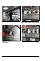
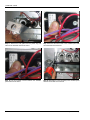
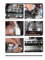
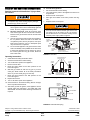
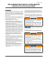
176958-UAI-A-0506
FIELD REPAIR PART INSTALLATION MANUAL
BRACKET KIT #S1-37323842001 and #S1-37323842002
FOR USE WITH GF8, G8C, UGA, AND P6UH SERIES FURNACES
APPLICATION
The accompanied brackets are designed for use with GF8,
G8C, UGA, and P6UH furnaces. These brackets are used to
eliminate the air leakage around the vestibule panel at the
burner box and prevent roll out switch nuisance tripping.
Please follow the instructions below as a guideline for installing the brackets.
• Bracket #176489 is installed on the top and bottom of the
vestibule panel burner box. The brackets are 18.85” in length
and are used on the 150,000 input models. The brackets
must be installed as shown in Steps 8, 9, 10, 11, 12, 13, and
16.
• Limit Gasket #176531 is installed on the backside of the
limit control. The limit gasket is used on all models. The limit
gasket must be installed as shown in Steps 17, 18, and 19.
There are two kits available. Kit #S1-37323842001 is for the
50,000 to 100,000 input models. Kit #S1-37323842002 is for
the 125,000 and 150,000 input models.
Kit #S1-37323842001 has the following parts:
• Bracket #176531 is installed on the left and right sides of
the vestibule panel burner box. The brackets are 2.95” in
length and are used on all the models. The brackets must be
installed as shown in Steps 14 and 15.
• Bracket #176533 is installed on the top and bottom of the
vestibule panel burner box. The brackets are 9.85” in length
and are used on the 50,000 input models. The brackets must
be installed as shown in Steps 8, 9, 10, 11, 12, 13, and 16.
• Bracket #176534 is installed on the top and bottom of the
vestibule panel burner box. The brackets are 9.80” in length
and are used on the 75,000 input models. The brackets must
be installed as shown in Steps 8, 9, 10, 11, 12, 13, and 16.
• Bracket #176532 is installed on the top and bottom of the
vestibule panel burner box. The brackets are 12.80” in
length and are used on the 100,000 input models. The
brackets must be installed as shown in Steps 8, 9, 10, 11,
12, 13, and 16.
• Limit Gasket #176531 is installed on the backside of the
limit control. The limit gasket is used on all models. The limit
gasket must be installed as shown in Steps 17, 18, and 19.
Kit #S1-37323842002 has the following parts:
• Bracket #176531 is installed on the left and right sides of
the vestibule panel burner box. The brackets are 2.95” in
length and are used on all the models. The brackets must be
installed as shown in Steps14 and 15.
• Bracket #176490 is installed on the top and bottom of the
vestibule panel burner box. The brackets are 15.85” in
length and are used on the 125,000 input models. The
brackets must be installed as shown in Steps 8, 9, 10, 11,
12, 13, and 16.
Improper installation may create a condition where
the operation of the product could cause personal
injury or property damage.
Improper installation, adjustment, alteration, service
or maintenance can cause injury or property damage. Refer to this manual for assistance, or for additional information, consult a qualified contractor,
installer or service agency.
INSTALLATION
The brackets must be installed by a certified dealer or qualified service contractor.
Following section contains pictures and step by step instructions to help guide you through the installation of this kit.
ELECTRIC SHOCK, FIRE OR EXPLOSION HAZARD.
Failure to follow safety warnings exactly could result
in dangerous operation, serious injury, death or
property damage.
Improper servicing could result in dangerous operation, serious injury, and death or property damage.
• Before installing the brackets, disconnect all electrical
power to the furnace.
• Label all wires prior to disconnecting. Reconnect wires
correctly.
• Verify proper operation after installing the brackets.
Before proceeding, be sure the area is well ventilated. Turn the thermostat OFF. If the blower is running, wait until it stops automatically. Turn OFF the
gas and electrical power supplies to the furnace.
Check all metal parts and surfaces to be sure they
have cooled to room temperature before you begin.
Unitary Products Group
176958-UAI-A-0506
Before proceeding with the installation of the brackets, refer
to the Startup and Shutdown instructions on page 8. Follow
these instructions to make sure the furnace has been properly shutdown and is safe to work on.
Step 3: Remove the electrical wires from the gas valve.
Step 1: Open the box and inspect the parts. Be sure the kit
has the correct brackets for the furnace model.
Step 4: Remove the wire ties that secure the sensor wire to
the burner manifold. Be careful not to cut the sensor wire.
Step 2: Open the front door to gain access to the burner
compartment.
2
Unitary Products Group
176958-UAI-A-0506
Step 5: Remove the sensor wire from the sensor.
Step 7: Remove the screw that secures the ignitor to the
bracket and remove the ignitor. Be extra careful not to touch
the ignitor to any surface. The ignitor is fragile and may be
easily broken.
Step 6: Unplug the ignitor wire.
Step 8: Remove the screws that secure the left and right
sides of the burner housing to the vestibule panel.
Unitary Products Group
3
176958-UAI-A-0506
Step 9: Remove the screws on the left and right sides at the
bottom that secure the burner housing to the fan deck and
remove the burner assembly.
Step 10: Remove the screw that secures the ignitor bracket
to the vestibule panel.
4
Step 11: Remove the screw that secures the rollout switch
bracket to the vestibule panel and the two screws to the right
of the rollout bracket.
Step 12: Install the angle bracket and secure to the vestibule
panel with the screws that were removed. Secure the rollout
switch bracket to the vestibule panel with the screw that was
removed.
Unitary Products Group
176958-UAI-A-0506
Step 13: Install the rollout bracket and secure to the vestibule
panel with the screws that were removed.
Step 14: Remove the screws on the left and right side of the
vestibule panel burner box.
Unitary Products Group
Step 15: Install the angle brackets on the left and right side of
the vestibule panel burner box. Secure to the vestibule panel
using the screws that were removed.
Step 16: Install the angle bracket on the bottom of the vestibule panel burner box. Secure to the vestibule panel using
the screws that were removed.
5
176958-UAI-A-0506
Step 17: Remove the limit gasket from the plastic bag and
install on the back side of the limit control.
Step 19: Secure the limit control to the vestibule panel with
the screws that were removed.
Step 18: The limit gasket must be between the vestibule
panel and the limit control.
Step 20: Reinstall the burner assembly to the vestibule panel
with the screws that were removed.
6
Unitary Products Group
176958-UAI-A-0506
Step 21: Reinstall the bottom burner assembly screws to the
fan deck with the screws that were removed.
Step 24: Reconnect the electrical wires to the gas valve terminals.
Step 22: Reinstall the ignitor with the nut that was removed.
Be sure that the ignitor stop is seated against the bracket.
Step 25: Reconnect the sensor wire to the sensor terminal.
Step 23: Reconnect the ignitor electrical plug.
Unitary Products Group
Step 26: Replace the wire ties that secure the sensor wire to
the gas manifold. Be sure to cut off the excess tie material.
7
START-UP AND SHUTDOWN INSTRUCTIONS
To Turn Off the Appliance:
Read the Instructions Below Before Trying to Start
the Furnace
1.
2.
3.
4.
B.
C.
D.
This appliance does not have a pilot. It is equipped
with an ignition device which automatically lights the
burner. Do not try to light the burner by hand.
BEFORE OPERATING; smell all around the appliance area for gas. Be sure to smell next to the floor
because some gas is heavier than air and will settle
on the floor.
Use only your hand to push the gas control switch to
the “on” position. Never use tools. If the switch will
not operate by hand, don’t try to repair it, call a qualified service technician. Force or attempted repair
may result in a fire or explosion.
Do not use this appliance if any part has been under
water. Immediately call a qualified service technician
to inspect the appliance and to replace any part of
the control system and any gas control, which has
been under water.
Should overheating occur, or the gas valve fail to
shut off, turn the external manual gas valve in the
gas supply line to the furnace to the “off” position
and let the furnace cool off before shutting off the
electrical power supply. Refer to Figure 5.
OUTLET
PRESSURE
PORT
INLET
VENT PORT
OUTLET
FF
WRENCH
BOSS
INLET
PRESSURE
PORT
O
N
A.
5.
O
If you do not follow these instructions exactly, a fire
or explosion may result causing property damage,
personal injury, and/or loss of life.
Set the thermostat to lowest setting.
Turn off all electric power to the appliance if service is to
be performed.
Remove burner access panel.
Move gas control switch to the “OFF” position. See Figure 1.
Replace burner access panel.
ON/OFF SWITCH
(Shown in OFF position)
FIGURE 1: Gas Valve
Operating Instructions:
STOP! Read the safety information above.
Set the thermostat to the lowest setting.
Turn off all electric power to the appliance.
Remove furnace door.
Move gas control switch to the “OFF” position. Do not
force. See Figure 1.
6. Wait five (5) minutes to clear out any gas. If you then
smell gas, STOP! Follow “B” in the safety information
above. If you don’t smell gas, go to next step.
7. Move gas control switch to the “ON” position. Do not
force. See Figure 1.
8. Replace burner door.
9. Turn on all electric power to the appliance.
10. Set thermostat to the desired setting. Burner will light,
which may take 30-60 seconds.
11. After three (3) trials for ignition, if the appliance will not
operate follow the instructions, “TO TURN OFF THE
APPLIANCE” and follow trouble shooting instructions as
required.
MAIN REGULATOR
ADJUSTMENT
EXTERNAL MANUAL
SHUTOFF VALVE
1.
2.
3.
4.
5.
TO GAS
SUPPLY
TO GAS
SUPPLY
DRIP
LEG
GROUNDED JOINT UNION
MAY BE INSTALLED
INSIDE OR OUTSIDE UNIT.
FIGURE 2: Gas Piping
MANUAL
SHUT-OFF
VALVE
GAS
PIPE
GAS
PIPE
DRIP
LEG
DRIP
LEG
GAS BURNERS
GAS VALVE
MANUAL
SHUT-OFF VALVE
FIGURE 3: Horizontal Gas Piping
Subject to change without notice. Printed in U.S.A.
Copyright © by York International Corp. 2006. All rights reserved.
Unitary
Product
Group
176958-UAI-A-0506
Supersedes: Nothing
5005
York
Drive
Norman
OK
73069