1
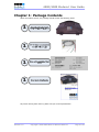
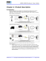
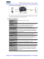
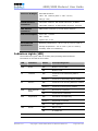
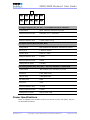
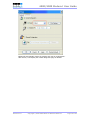
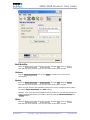
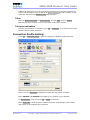
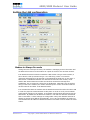
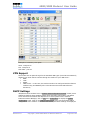
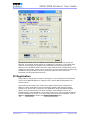
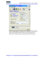
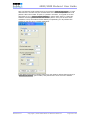
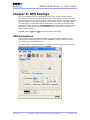
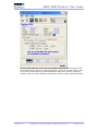
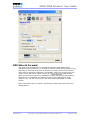
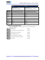
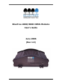
BlueTree 4000/5000 CDMA Modems User’s Guide June 2006 (Rev 1.0) BlueTree Wireless Data, Inc. 2425 46th Avenue Lachine, QC, Canada H8T 3C9 Tel: +1 (514) 422-9110 Toll Free: 1-877-422-9110 www.bluetreewireless.com Copyright © 2004/2005 by BlueTree Wireless Data, Inc. All Rights Reserved Printed in Canada BlueTree™, the BlueTree logo, and BlueVue™ are trademarks of BlueTree Wireless Data, Inc. All other trademarks are the property of their respective owners. Declaration of Conformity FCC Compliance and Industry Canada Statement FCC & Industry Canada IDs for the 4200/5200: O9EQ2438 & 3651C-Q2438 FCC & Industry Canada IDs for the 4600/5600: QWV-BTX600 & 4420A-BTX600 The device complies with Part 15 of FCC rules and with ICES-003 of Industry Canada Rules. Operation is subject to the following two conditions: 1. This device may not cause harmful interference. 2. This device must accept any interference received, including interference that may cause undesired operation. Caution: Unauthorized modifications or changes not expressly approved by BlueTree Wireless Data, Inc. could void compliance with regulatory rules, and thereby your authority to use this equipment. This equipment generates uses and can radiate radio frequency energy and, if not installed and used in accordance with the manufacturer's instructions, may cause interference harmful to radio communications. However, there is no guarantee that interference will not occur in a particular installation. If this equipment does cause harmful interference to radio or television reception, which can be determined by turning the equipment off and on, the user is encouraged to try to correct the interference by one or more of the following measures: Reorient or relocate the receiving antenna. Increase the separation between the equipment and receiver. Connect the equipment into an outlet on a circuit different from that to which the receiver is connected. Consult the dealer or an experienced radio/TV technician for help. Warning: “Antenna must not exceed 3 dBi for Cellular band and 4 dBi for PCS band. This device must be used in mobile configurations. The antenna(s) used for this transmitter must be installed to provide a separation distance of at least 30 cm or 12 inches from all persons and must not be co-located or operating in conjunction with any other antenna or transmitter. Users and Installers must be provided with antenna installation instruction and transmitter operating conditions for satisfying RF exposure compliance” Liability Notice While every effort has been made to achieve technical accuracy, information in this document is subject to change without notice and does not represent a commitment on the part of BlueTree Wireless Data, Inc., or any of its subsidies, affiliates, agents, licensors, or resellers. There are no warranties, express or implied, with respect to the content of this document. Safety Do not operate the BlueTree Wireless Data modems in areas near medical equipment, where blasting is in progress, where explosive atmospheres may be present, or near any equipment that may be susceptible to any form of radio interference. CONTENTS Chapter 1: Package Contents....................................................................... 6 Chapter 2: Product Description.................................................................... 7 Introduction..................................................................................................... 7 Modem Views................................................................................................... 9 Summary of Specifications................................................................................. 9 Indicators Lights (LED).................................................................................... 10 Data Interface Specifications: Serial, USB, Ethernet ............................................ 11 General Purpose Input and Outputs Specifications ............................................... 11 Power Specifications ....................................................................................... 12 Chapter 3: BlueVue Device Manager ...........................................................14 Chapter 4: Wireless WAN Setup..................................................................15 Activation...................................................................................................... 15 Connection Profile Setting................................................................................ 19 Test your connection....................................................................................... 20 Chapter 5: LAN Setup .................................................................................21 Dialup Networking .......................................................................................... 21 Setting the LAN configuration ........................................................................... 22 Ethernet........................................................................................................ 23 USB RNDIS.................................................................................................... 23 Chapter 6: IP Networking Features ............................................................24 Port Forwarding.............................................................................................. 24 VPN Support .................................................................................................. 25 DHCP Settings ............................................................................................... 25 IP Registration ............................................................................................... 26 Chapter 7: Serial IP – Packet Assembly Disassembly .................................28 Chapter 8: GPS Settings..............................................................................30 GPS Destinations............................................................................................ 30 GPS Configuration .......................................................................................... 31 GPS Store & Forward ...................................................................................... 33 Chapter 9: IO Management.........................................................................35 Digital Output Control ..................................................................................... 35 Digital Input State Query................................................................................. 35 Analog Input Value Query ................................................................................ 35 Chapter 10: Event Reporting ......................................................................36 Digital Input Monitoring................................................................................... 36 Ignition ON/OFF Notification............................................................................. 36 Analog Input Monitoring .................................................................................. 36 Low Voltage Notification .................................................................................. 36 Time Interval Event Reporting .......................................................................... 36 GPS-driven Event Reporting ............................................................................. 36 Excessive Speed Notification ............................................................................ 36 Engine Idling Notification ................................................................................. 36 Odometer Measurement .................................................................................. 36 Chapter 11: Firmware Upgrade...................................................................37 Chapter 12: Hardware Installation .............................................................38 Cellular antenna ............................................................................................. 38 GPS antenna.................................................................................................. 39 Serial cable ................................................................................................... 40 Ethernet cable................................................................................................ 40 USB cable...................................................................................................... 40 Power source ................................................................................................. 40 IO Cable Wiring.............................................................................................. 42 Mounting the modem ...................................................................................... 43 Appendix A: Warranty and Support ...............................................................44 Warranty....................................................................................................... 44 Customer Support .......................................................................................... 44 4000/5000 Modems’ User Guide Chapter 1: Package Contents When the modem arrives, the package should contain the following items: Any items missing from this list, please call your local representative. Revision 1.0 Copyright © 2004-2006 BlueTree Wireless Data Inc. Page 6 of 44 4000/5000 Modems’ User Guide Chapter 2: Product Description Introduction BlueTree 4000/5000 series modems are rugged wireless modems built to provide simple and reliable communications over the CDMA wireless data network to applications such as Public Safety, Field Force Automation, Asset Tracking, Telemetry, Meter Reading and WAN backup. The modem manages two connections at the same time, thus acting as a gateway/router: Wireless WAN connection: this is the Wide Area Network connection to the wireless network. The modem is typically configured to autonomously establish a packet data connection to the wireless carrier and acquire a WAN IP address. The LAN connection: this is the Local Area Network connection between the modem and any terminal attached to its serial/USB/Ethernet ports. The modem in this case acts as a server and assigns a private LAN IP address to the attached terminal. Revision 1.0 Copyright © 2004-2006 BlueTree Wireless Data Inc. Page 7 of 44 4000/5000 Modems’ User Guide The modem then routes packets back and forth between its WAN and LAN connections by performing Network Address Translation (NAT’ing). Summary of Features 3 different data connection interfaces Serial/RS-232, Ethernet, and USB. Autonomous connection management Fully integrated TCP/IP protocols allowing the modem to connect autonomously to the packet network (internet). This feature enables capabilities such as: In-call diagnostic, Serial-IP, stand-alone GPS, remote configuration, and remote firmware upgrade. Network Address Translation (NAT) Remote applications use the WAN IP address of the modem as the destination IP address. The traffic received by the modem on various ports is forwarded according to their ports and their corresponding port forwarding rules to a LAN IP address In-call diagnostic Allows the user to get modem status information while in a data call, without interrupting the data session. Serial-IP Encapsulates data coming from the serial port into a TCP or UDP packet and sends it to a remote server on the packet network. Decapsulates IP packets coming from the network and sends raw data to the serial port. Remote configuration Using the BlueVue Device Manager or terminal session, this feature allows the administrator to remotely configure or perform remote diagnostics on the modem. Remote firmware upgrade Using the BlueVue Device Manager, this feature allows the administrator to remotely upgrade the modem’s firmware. Integrated GPS Receiver A Trimble GPS receiver is embedded into the modem for Automatic Vehicle Location (AVL). The modem can report this positioning data locally to any of the data interfaces (serial, Ethernet, USB), or also remotely to a predefined server (see stand-alone). Available on the 5000 series modems only. Revision 1.0 Copyright © 2004-2006 BlueTree Wireless Data Inc. Page 8 of 44 4000/5000 Modems’ User Guide Stand-alone GPS Available on the 5000 series modems only. This feature allows remote asset tracking by sending GPS data to a remote server without the need for a client application on the data terminal. GPS Store and Forward Available on the 5000 series modems only. This feature allows GPS data storage. If a unit loses communication, the data being collected through GPS will be stored in memory and forwarded when communication is reestablished. Inputs and Outputs Sensors can be connected to the I/O port of the 4000/5000 series modems (4 digital inputs, 3 digital outputs and 3 analog inputs). The modem is capable of monitoring its digital input sensors for any change in state and sending a report to a remote server based on an event trigger. The analog inputs allow monitoring of gradient data sources. Event Reporting 4000/5000 series modems send a report to remote server based on an event trigger. The modem has an intuitive embedded Event Reporting Protocol that automatically formats the messages reported to the remote server. Modem Views Front Panel Rear panel Summary of Specifications CDMA Dual-band Supports both North American frequency bands: 800 and 1900 MHz CDMA 1xRTT and 1xEvDO Compatible with CDMA IS-2000 (1xEvDO) Wireless data services. Backward compatible with IS95 protocols. Data Rates 1xRTT: 153.6 Kbps up and down streams EvDO : 2.4 Mbps downstream & 153.6 Kbps upstream Programming/Setup BlueVue Device Manager software, AT commands LED Status Indicators PWR, TX, RX, DTR, REG, LNK, ACT, SER or GPS Revision 1.0 Copyright © 2004-2006 BlueTree Wireless Data Inc. Page 9 of 44 4000/5000 Modems’ User Guide Enclosure & Weight Extruded Aluminum 166 × 127 × 56 mm (6.55” × 5.00” × 2.20”) 500g (1.1 lbs) Cellular Antenna Connection 4200/5200 modems: TNC Female Connector, 50 Ohms GPS Antenna Connection SMA Female Connector (3.3 Volts active antenna) Power Consumption Active call: ~170mA 4600/5600 modems: 2x SMA Female Connector, 50 ohms Idle: ~50mA Ignition off: ~1mA Environmental Specifications Operating Temperature: -30° to +70° C (-22° to +158° F) Storage Temperature: -40° to +85° C (-40° to +185° F) Humidity: 95% non-condensing Indicators Lights (LED) The modem has 8 green LEDs on its front panel providing fast and efficient information on the state of the modem: LED Indication Status Corresponding State PWR Power OFF Modem is turned OFF. ON Modem is ON. OFF Terminal is not transmitting data to modem. Flashing Terminal is transmitting data to modem. OFF Terminal is not receiving data from modem Flashing Terminal is receiving from modem Data Terminal Ready OFF No terminal is detected ON Terminal host is detected Registration OFF RF module not responding Flashing Registered on network ON Not registered OFF Not in a call ON In a data call OFF No transmit/receive from network TX RX DTR REG LNK ACT Revision 1.0 Transmit Receive RF link RF activity Copyright © 2004-2006 BlueTree Wireless Data Inc. Page 10 of 44 4000/5000 Modems’ User Guide GPS GPS Flashing Transmitting/receiving data from network OFF No position fix available Flashing Once for every GPS message received Data Interface Specifications: Serial, USB, Ethernet Serial Port (DB9) The modem’s serial port is an RS232 DCE, compliant with EIA-232 standard. The connector used is DB9 female and is shown in the illustration below. Pin number Name Description Direction 1 DCD Data Carrier Detect Modem to PC 2 RXD Receive Data Modem to PC 3 TXD Transmit Data PC to Modem 4 DTR Data Terminal Ready PC to Modem 5 GND Ground Common 6 DSR Data Set Ready Modem to PC 7 RTS Request To Send PC to Modem 8 CTS Clear To Send Modem to PC 9 RI Ring Indicator Modem to PC USB Device Port This is a USB2.0 Device interface on a Type B connector. Ethernet Port The modem 10/100Mbps Ethernet port is compliant to EIA-568 standard, and requires a crossover cable to connect to host terminals. General Purpose Input and Outputs Specifications The modem has 4 digital inputs, 3 digital outputs and 3 analog inputs for remote control and monitoring. Revision 1.0 Copyright © 2004-2006 BlueTree Wireless Data Inc. Page 11 of 44 4000/5000 Modems’ User Guide 3x Digital Outputs (O1, O2, O3) – O3 available on Power connector Configuration Open Collector, reference to ground Absolute Maximum IDC 500mADC (Vce = 750mVDC) Absolute Maximum VDC 30VDC (open circuit) Absolute Minimum VDC 0.4VDC (open circuit) 4x Digital Inputs (DI1, DI2, DI3, DI4) Configuration Non-isolated level detection, reference to ground Active level 1.6VDC to 30VDC Inactive level 0VDC to 1.3VDC Absolute Minimum VDC 0.3VDC Absolute Maximum VDC 33VDC Leakage IDC at 5VDC 150uADC 3x Analog Inputs (AI1, AI2, AI3) – AI3 only available on 4600/5600 Configuration Not isolated input, reference to ground Resolution 1024 (ADC 10-bit) VDC per step 4.8875855mVDC Full scale level 5VDC Zero level 0VDC Absolute Minimum VDC -0.3VDC Absolute Maximum VDC 8.3VDC Leakage IDC at 5VDC 265.96 uADC TYPE Power Specifications Power is supplied to the modem via the 4-pin connector on the rear panel. The pins are described as follows: Revision 1.0 Copyright © 2004-2006 BlueTree Wireless Data Inc. Page 12 of 44 4000/5000 Modems’ User Guide O3 IGN GND POS Pin number Name Description 1 GND Ground 2 POS Power supply input 8 to 30 Vdc 3 IGN Ignition sense input – turns ON/OFF the modem 4 O3 Digital Output 3 Power input to the modem is protected against reverse polarity and overvoltage. The POS input is also monitored by the modem as a dedicated analog input. The IGN input is also monitored by the modem as a dedicated digital input. Current consumption Active mode: Æ the modem is in a call and is transmitting or receiving data Average of 169mA @ PCS 1900Mhz (Peak: 286 mA) Average of 154mA @ Cellular 800Mhz (Peak: 268 mA) Idle mode: Æ the modem is either not in a call, or is in one but is Dormant Æ Dormant is the state the modem is in after 20sec of inactivity 49mA Ignition OFF: Æ the modem is turned OFF but still has power from its POS input Æ all circuitry is shutdowns except for Non-Volatile memory and Real Time Clock 1mA Revision 1.0 Copyright © 2004-2006 BlueTree Wireless Data Inc. Page 13 of 44 4000/5000 Modems’ User Guide Chapter 3: BlueVue Device Manager The 4000/5000 series modems are configured with BlueVue Device Manager (BVDM) software utility. BVDM allows users to: Provision modem on wireless network (WAN Setup) Configure operation parameters (LAN Setup and GPS) Monitor diagnostic and status information Perform a firmware upgrade on the modem Note: Refer to BlueVue Device Manager manual for full details. BVDM is available on BlueTree’s website, under the Support section: http://www.bluetreewireless.com/support/downloads Revision 1.0 Copyright © 2004-2006 BlueTree Wireless Data Inc. Page 14 of 44 4000/5000 Modems’ User Guide Chapter 4: Wireless WAN Setup Activation Getting an account for your modem Contact your wireless service provider and request a CDMA account activation with the “packet data” service option for 1xEvDO or 1xRTT. You will need to provide the service provider the Electronic Serial Number (ESN) of the modem you wish to activate. The ESN is located on a label under the modem. The wireless service provider should give you the following credentials for you to complete the activation: Mobile Directory Number (MDN): the 10-digit telephone number assigned to your unit, including the area code Master Lock Code (MSL): the 6-digit number representing the Service Provisioning Lock Code, if not provided then assume it’s 000000 Mobile Station ID (MSID or IMSI or MIN): the 10-digit or 15-digit number required for Local Number Portability, if not provided then assume it’s the same as the MDN Username/Password for packet network access Note: Keep a written record of the account information that your wireless service provider gives you. Store it in a secure location. You will need this information if required to re-enter the account information. Provisioning the account credentials into the modem A serial connection is required between your PC and the modem for this process. Run BVDM, and from Tools > Settings, make sure you select the PC’s COM port to which the modem is attached (as shown in the figure below): Revision 1.0 Copyright © 2004-2006 BlueTree Wireless Data Inc. Page 15 of 44 4000/5000 Modems’ User Guide BVDM will automatically detect the modem and read its configuration. After which, it will display the modem diagnostic page as follows: Revision 1.0 Copyright © 2004-2006 BlueTree Wireless Data Inc. Page 16 of 44 4000/5000 Modems’ User Guide Go to File > Activation Revision 1.0 Copyright © 2004-2006 BlueTree Wireless Data Inc. Page 17 of 44 4000/5000 Modems’ User Guide Bell Mobility Enter the Master Lock Code, the phone number, and the MSID, then hit Submit. Note that has to be entered, even if it’s the same as the phone number. Verizon Click on Carrier Provisioning then select OTASP to initiate over the air service provisioning. Sprint Enter the Master Lock Code, the phone number, and the MSID, then hit Submit. Note that has to be entered, even if it’s the same as the phone number. IOTA: once the account info submitted, initiate over the air activation process (IOTA) by clicking Carrier Provisioning then IOTA buttons. Datalink: if you have acquired a Datalink account, make sure you load the appropriate access credential parameters provided by Sprint by clicking Carrier Provisioning then Datalink buttons. Alltel Enter the Master Lock Code, the phone number, and the MSID, then hit Submit. Note that has to be entered, even if it’s the same as the phone number. Revision 1.0 Copyright © 2004-2006 BlueTree Wireless Data Inc. Page 18 of 44 4000/5000 Modems’ User Guide If Mobile IP settings are to be set, then click on Mobile IP and verify the right settings needed. The RF module is set to operate in Mobile IP Preferred mode. Typically, a user could alter that setting to Mobile IP Only mode if desired. Telus Enter the Master Lock Code, the phone number, and the MSID, then hit Submit. Note that has to be entered, even if it’s the same as the phone number. Test your activation Once the process above is completed, go to File > Diagnostic: you should see the valid modem’s phone number displayed. Connection Profile Setting Go to File > Connection Profile in order to configure the Modem’s WAN connection. Enter #777 as a Dial String to establish a packet data call (1xRTT or EVDO). Enter Username and Password as provided by your wireless service provider. For PPP Protocols, make sure both PAP & CHAP are selected. Select Always On in order to set the modem to connect automatically to the network upon power up and maintain this connection. Revision 1.0 Copyright © 2004-2006 BlueTree Wireless Data Inc. Page 19 of 44 4000/5000 Modems’ User Guide Always On versus On Demand When the modem is set in Always On mode, it performs as a separate entity in relation with the wireless network. Thus, the modem is managing its own connection and an attached host must use the modem as a point of access to the wireless network. When set in On Demand mode, the modem is no longer in autonomous connection mode. Connection management in that case is performed by an attached terminal. The most common scenario is to use the serial port in order to establish a PPP session. Test your connection Once the process above is completed, go to File > Diagnostic: you should see the valid modem’s WAN IP displayed, this is the IP address that has been assigned to the modem by the wireless carrier. At the same time, you should see the modem’s LNK light solid ON. Revision 1.0 Copyright © 2004-2006 BlueTree Wireless Data Inc. Page 20 of 44 4000/5000 Modems’ User Guide Chapter 5: LAN Setup Dialup Networking Some attached terminals do not have RJ45 Ethernet connectors and demand using a DB9 RS232 standard serial connector for proper interface with the modem. The most common use of this is in a PC environment and what is commonly referred to as dialup networking. A user must install a standard modem driver at the appropriate COM port at which the modem is physically connected then create a dial-up connection running on that driver. The dial-up connection dials #777 to reach to the modem so that a PPP session is established between modem and PC. In the mean while, an already established PPP session between modem and wireless network is underway. There are 2 steps in setting up a PPP connection from your PC. They are described here using Windows XP OS. Adding a modem driver 3. Click Start > Settings > Control Panel > Phone and Modem Options 4. On the Phone and Modem Options box, click the Modems tab and then click Add 5. Check the box labeled Don’t detect my modem… and then click Next 6. Select the Standard 33600 bps Modem and click Next 7. Select the COM port that the modem is attached to then click Next 8. Click Finish to complete the addition of the modem in Windows 9. Click the Modem tab and confirm that the Maximum Port Speed is set to 115,200 10. Click OK The modem profile is now configured. Creating a DUN session 11. Click Start > Settings > Control Panel > Network Connects > New Connection Wizard 12. On the New Connection Wizard welcome box click Next 13. On the Network Connection Type box select Connect to the Internet, and then click Next 14. On the Getting Ready box select Set up my connection manually, and then click Next 15. On the Internet Connection box select Connect to a dialup modem, and then click Next 16. On the Select a Device box select the Standard 33600bps modem and then click Next 17. On the Connection Name box, type in a name for the connection (for example: CDMA) and then click Next 18. On the Phone Number to Dial box type the phone number, as supplied by your wireless service provider. For example, type #777 for 1xRTT or 1xEvDO packet data connections 19. On the Internet Account Information box, type the username and password in the corresponding fields and then click Next The DUN connection is now set up and ready to connect to the wireless network. Revision 1.0 Copyright © 2004-2006 BlueTree Wireless Data Inc. Page 21 of 44 4000/5000 Modems’ User Guide Setting the LAN configuration Modem in Always On mode Having been set in Always On mode, the modem is managing its own connection and an attached host must use the modem as a point of access to the wireless network. If an attached terminal intends to establish a PPP session using a serial interface, it has to launch a dial up session using a #777 dial string. There is no need for username and password to be entered on the attached terminal side. In this case, a PPP session is established between the attached terminal and the modem; while another PPP session between modem and wireless network has already been established. This is commonly referred to as double PPP. Note that if the wrong dial string is sent to the modem, the modem would drop the current connection with the wireless network and defer to On Demand mode. It is essential that both the modem and the attached terminal be within the same LAN in order for proper IP communication to take place. In order to verify correct LAN IP configuration settings on the modem, go to Modem Configuration page and check the PPP section. By default the IP address of modem is 192.168.0.2 and that of attached host is 192.168.0.3. These settings are configurable. Verify that attached terminal is allowed to accept an IP address automatically; if not, set the IP address of modem to accommodate the IP address of attached terminal so as both would lie within the same subnet. Revision 1.0 Copyright © 2004-2006 BlueTree Wireless Data Inc. Page 22 of 44 4000/5000 Modems’ User Guide Modem in On Demand mode The modem at this point is not managing its own connection. The attached terminal should run a dial up session where the proper username, password, and dial string need to be entered. The modem at this point is behaving just like any other dial-up modem. Ethernet If an Ethernet interface is available on the attached terminal side, there is no need to establish a PPP session. Plugging in an appropriate Ethernet cable would guarantee IP layer-3 communication. However, it is essential to set the LAN IP configuration on the modem so that both modem and terminal lie within the same subnet. Go to Modem Configuration page and click on LAN IP Configuration tab. The default LAN IP address of the modem on the Ethernet side is 192.168.0.1 and that of the attached host is 192.168.0.4. Confirm that attached terminal is set to accept an IP address automatically. If it has been assigned a static IP address, then set the modem such that it has a LAN IP address that lies within the same subnet as that of the terminal. In this case, it is preferable to disable the DHCP server on the modem or set the DHCP range such that the attached host will only acquire the same IP address from the modem at all times. USB RNDIS Revision 1.0 Copyright © 2004-2006 BlueTree Wireless Data Inc. Page 23 of 44 4000/5000 Modems’ User Guide Chapter 6: IP Networking Features As briefly mentioned in Chapter 1, the modem acquires an IP address from the wireless network upon establishing a connection. The modem runs its own IP stack, thus allowing a remote user to communicate with the modem or an attached terminal behind the modem accordingly. This could be done via any terminal session, BVDM, or any software application that is using the WAN IP address of the modem and the appropriate port number as destination parameters. It is important to note that some carriers limit this feature and a user has to particularly ask the carrier for allowing incoming IP data traffic. Also, if the intended party to be reached is a terminal behind the modem, the appropriate port forwarding and LAN IP configuration settings have to be set. Remote connectivity feature also is vital for remote modem diagnostics or AT command interface. Port Forwarding Port forwarding (also referred to as tunneling) is the act of forwarding a network port from one machine to another. One use of this technique can allow an external user to reach a port on a private IP address from the outside via a NAT (network address translation) -enabled router. This allows remote computers to connect to a specific computer within a private LAN, depending on the port used to connect. Since the 4000/5000 series modem is a NAT enabled router. The WAN device connecting to the modems wireless WAN IP can not access devices/servers on the LAN without specifically configuring the modem to forward the port(s) to the LAN devices/servers. Applications running on remote hosts or servers connect to the modem via the internet and the 1xRTT network. Below is an exemplar sketch of how different applications running on various servers are able to reach their intended destinations (PCs in this particular case). The PCs are connected to the BlueTree modem – via Ethernet crossover cable, hubs and patch cables, wireless router or a wireless access point. In the case below a wireless access point is used and is connected via an Ethernet cable to the BlueTree modem. The remote applications use the wireless IP address of the modem (the WAN IP assigned by the wireless network carrier) as the destination IP address. The traffic received by the modem on various ports are forwarded according to their ports and their corresponding port forwarding rules to a LAN IP address. To set Port Forwarding, click on the Port Forwarding tab. The WAN Port is the destination port number used by the remote application. The LAN Port is where the data is forwarded to; typically the WAN port and LAN port are the same. Select the appropriate protocol (TCP or UDP). Submit the new settings after editing this page. Revision 1.0 Copyright © 2004-2006 BlueTree Wireless Data Inc. Page 24 of 44 4000/5000 Modems’ User Guide Examples of commonly used ports: HTTP - TCP port 80 FTP - TCP port 21 TFTP UDP – port 69 VPN Support The modem acts as pass-through for the standard VPN types (Virtual Private Network) allowing your client VPN to connect through the modem to your VPN server: PPTP L2TP IPSEC GRE Tunnel – in this case, the modem needs to be configured with this feature enabled using AT+BGREIP (refer to the BlueTree AT Command Reference document) DHCP Settings 4000/5000 series modems have a Dynamic Host Configuration Protocol (DHCP) server enabled by default. DHCP enables TCP/IP client automatic configuration. The DHCP server stores IP information and disperses it to client systems on the network. In BlueVue Device Manager, click on File then Configuration to display the Modem Configuration page. Click on the LAN IP Configuration tab to see the default LAN IP configuration of the modem. In the Ethernet section, the DHCP settings are displayed. Revision 1.0 Copyright © 2004-2006 BlueTree Wireless Data Inc. Page 25 of 44 4000/5000 Modems’ User Guide By default the DHCP server is enabled. If connecting a terminal to the modem via Ethernet, the terminal should acquire an IP address of 192.168.0.4. The DHCP range could be set accordingly or disabled if the attached host requires a particular IP address. If the IP address of the terminal is hard coded, then the modem DHCP server settings are overridden; in that case it is necessary to verify that both the modem LAN IP address and the IP address of the terminal are within the same subnet for successful communication between both. IP Registration The modem is configurable to report a message to a user-configurable IP destination every time its WAN IP address is changed. This is the IP address assigned by the wireless carrier. The benefits of this feature are mainly when CDMA accounts have a dynamic IP address. Certain applications require exchanging IP data traffic with the modem, typically over TCP or UDP. In that case, the application needs the WAN IP address (public) of the modem before such data exchange. If the CDMA account is not equipped with a static IP address, the modem can be set to report its WAN IP address to an IP destination of choice, over TCP or UDP. In BlueVue Device Manager, click on File then Configuration to display the Modem Configuration page. Revision 1.0 Copyright © 2004-2006 BlueTree Wireless Data Inc. Page 26 of 44 4000/5000 Modems’ User Guide Select Dynamic IP Registration and populate the necessary information for the modem to report its WAN IP address. The reporting timer is defaulted to zero, which allows the modem to report its WAN IP address upon boot up or upon losing the wireless connection for any apparent reason or upon acquiring a new IP address from the wireless carrier. The reporting timer is in minutes. Minimum timer is one minute. Revision 1.0 Copyright © 2004-2006 BlueTree Wireless Data Inc. Page 27 of 44 4000/5000 Modems’ User Guide Chapter 7: Serial IP – Packet Assembly Disassembly The purpose of this feature is to enable access to remote legacy devices (with no TCP/IP stack) over the wireless packet network. This feature is particularly used in telemetry applications such meter reading and SCADA devices. In case of a serial connection between an attached terminal and the modem, there are instances when data exchanged between the terminal and modem is not IP traffic but raw serial data (typically layer 2 data). In this case, the modem operational mode should be set to Serial IP. When set in Serial IP mode, upon reception of the IP packets, the modem strips off the IP headers from those packets and sends them to the attached device as raw data perceived correctly by the device. When the device is sending data, the modem encapsulates the data in IP packets to be transmitted over-the-air to an assigned destination. Flush parameters are essential for precise local serial communication. Such parameters are directly related to the type of protocol running on the attached device at the data link layer level. Depending on the type of application (direction of data traffic) and type of IP protocol used, the modem should be set accordingly. If the attached terminal is queried by a remote application, the Serial IP Listening Server on the modem should be configured accordingly. The modem performs socket handling on its own end according to IP packets received from the remote application. The flush parameters determine the encapsulation of data received from attached terminal. Flush on time out parameter is a multiple of 100 milliseconds, which is the Revision 1.0 Copyright © 2004-2006 BlueTree Wireless Data Inc. Page 28 of 44 4000/5000 Modems’ User Guide time out between serial packets sent by the terminal. Flush on byte count is in bytes determines the number of bytes received before the modem encapsulate data in IP packets. When the number of bytes in a packet is unknown, it is typical to set this parameter to zero. Flush on special character is utilized when there is a particular character that designates the end of a received packet. If any one of those three conditions is met, the modem flushes data by encapsulating it in IP packets then sending it over the air to a remote application. If the attached terminal is sending data on its own initiative without being queried, a destination IP address, port number, and protocol have to be set on the modem. Revision 1.0 Copyright © 2004-2006 BlueTree Wireless Data Inc. Page 29 of 44 4000/5000 Modems’ User Guide Chapter 8: GPS Settings This is an available feature in 5200/5600 modems only. These modems have an embedded GPS receiver from which the processor on the modem retrieves GPS data. GPS data retrieved is not processed by the modem. The interface, available in BlueVue Device Manager, to control GPS reporting communicates directly to the GPS module. For construction of customized reports of GPS data, a user has to leverage the AVL (Automatic Vehicle Location) and Event Reporting firmware capabilities of the modem. Firmware 2.0.3 and above allow AVL capabilities. Refer to Blue Tree’s website for latest firmware updates. In BVDM, click on File then GPS to access the modem GPS page. GPS Destinations It is possible to select two GPS Destinations by populating IP Destinations 1 & 2; selecting the IP Transport protocol for each destination; filling in the Port number; then checking the IP Destination box. It is also possible to report GPS data on a serial port by checking the Serial Port box. Execute and save settings by clicking on Submit. Revision 1.0 Copyright © 2004-2006 BlueTree Wireless Data Inc. Page 30 of 44 4000/5000 Modems’ User Guide GPS Configuration Select a protocol type, TAIP or NMEA. Populate the corresponding Acquisition Time (sec) and Reporting frequency (sec).Reporting Timer can not carry a value smaller than the Acquisition Timer. Typically, both timers should be set to the same value. If not, the modem reports the number of fixes it has acquired before the reporting timer has expired. In case of NMEA, select the NMEA messages to be transmitted. A user can select which messages to be reported and set the reporting based on time interval. It is important to note that in NMEA standards there is no unique identifier for the NMEA message. If a unique identifier is necessary, the user has to either utilize TAIP GPS reporting protocol or leverage the AVL firmware capabilities of the modem. By default, the modem reports GGA and VTG messages. Refer to Trimble NMEA documentation for format of reported NMEA messages. Revision 1.0 Copyright © 2004-2006 BlueTree Wireless Data Inc. Page 31 of 44 4000/5000 Modems’ User Guide In case of TAIP reporting, a user can set a complete TAIP command. Reporting could be set based on time interval or distance traveled. A vehicle ID could be entered. This entry will be incorporated in the TAIP initialization string which could be configured manually. Refer to Trimble TAIP documentation for format of TAIP reported messages. Revision 1.0 Copyright © 2004-2006 BlueTree Wireless Data Inc. Page 32 of 44 4000/5000 Modems’ User Guide GPS Store & Forward The 5000 series modems have an integrated 512Kbytes Static RAM memory dedicated to storing GPS fixes. It can store an average of 5000 points (position fixes), depending on the protocol selected. Its purpose is to keep a record of the vehicle’s route when the reporting destination is unreachable. Under such circumstances, the modem stores GPS data in a static memory in a First In First Out (FIFO) manner. When the wireless connection is re-established or when the socket at the reporting destination is re-established, the modem resumes sending GPS packets. If the memory is full, the new fixes overwrite the oldest stored ones based on a FIFO process. Refer to the table below as a guide in calculating the total storage time and size of related packets. Revision 1.0 Copyright © 2004-2006 BlueTree Wireless Data Inc. Page 33 of 44 4000/5000 Modems’ User Guide NMEA TAIP Content = RMC Message Size = 67 Bytes Number of recorded points = 8,000 Content = PV Default Message Size = 35 Bytes Number of recorded points = 14,900 Acquisition Interval Total Storage Time (in hours) Total Storage Time (in hours) 5 sec 11 20.69 15 sec 33 62.07 30 sec 66 124.14 60 sec 132 248.28 15 min 1980 3724.2 30 min 3960 7448.4 60 min 7920 14896.8 NMEA Message Packet Size When selecting NMEA as the reporting protocol, you can choose which specific message(s) to report: GGA GPS Fix Data 75 Bytes GLL Geographic Position Longitude/Latitude 48 Bytes GSA GPS DOP and Active Satellites 63 Bytes GSV Active Satellites in View 70 Bytes RMC Recommended Minimum Specific 67 Bytes VTG Track Made Good and Ground Speed 37 Bytes ZDA Time & Date 35 Bytes Revision 1.0 Copyright © 2004-2006 BlueTree Wireless Data Inc. Page 34 of 44 4000/5000 Modems’ User Guide Chapter 9: IO Management BlueTree offers a complete set of AT commands to query/set its general purpose and dedicated input and output pins. These commands can be sent to the modem: Locally via the serial, USB or Ethernet ports Remotely over the air Please refer to BlueTree’s AT Command Reference document for more details: http://www.bluetreewireless.com/support/downloads/documents/ Digital Output Control The three outputs on the modem an be used to turn ON or OFF peripheral equipment such as light, a siren, a valve, lock/unlock a door, enable/disable a starter,… Example of turning ON digital output 2: AT+BDOSET=DO2,1. Digital Input State Query The modem monitors all of its 4 general purpose digital inputs for a change in state, along with the dedicated ignition input. The state of these inputs can be queried as follows: AT+BDIGET? +BDIGET: DI1,0 +BDIGET: DI2,0 +BDIGET: DI3,0 +BDIGET: DI4,0 +BDIGET: IGN,1 OK Analog Input Value Query The modem has an 10-bit ADC (analog to digital converter) allowing it to monitor all of its 3 general purpose analog inputs for a change in state, along with the dedicated power input. The value of these inputs can be queried as follows: AT+BAIGET? +BAIGET: PWR,13.553 +BAIGET: AI1,3.056 +BAIGET: AI2,1.987 +BAIGET: AI3,0.000 OK Revision 1.0 Copyright © 2004-2006 BlueTree Wireless Data Inc. Page 35 of 44 4000/5000 Modems’ User Guide Chapter 10: Event Reporting Digital Input Monitoring The modem can be configured to monitor any or all of its 4 digital inputs for a change in state. Once the change in state is detected, the modem would send a report to the user configurable IP destination. Ignition ON/OFF Notification The modem can be configured to monitor this input for a change in state. Once the vehicle’s ignition is turned ON or OFF, the modem would send a report to the userconfigurable IP destination. Analog Input Monitoring The modem can be configured to monitor any or all of its analog inputs. Once the set threshold is reached, the modem would send a report to the user-configurable IP destination. The report event can be based on: Input value is equal to the set threshold Input value dropped below the set threshold Input value exceeded the set threshold Low Voltage Notification The modem continuously monitors this input, and is configurable to report a low voltage alert to a user-configurable IP destination once the voltage drops below a certain threshold. Time Interval Event Reporting The modem is configurable to report a GPS, IO info, or diagnostic message every x seconds to a predetermined IP destination. GPS-driven Event Reporting The user can set the reporting system to trigger whenever the GPS receiver reports a fix. In effect, this makes the reporting system follow the settings of the embedded GPS receiver. Excessive Speed Notification The user can define a speed threshold and trigger a notification whenever the speed reported by the GPS receiver exceeds that threshold. Engine Idling Notification The user can define an event to notify of an engine Idling state. This can be accomplished by defining a trigger that combines a low speed threshold (e.g. <=5 km/h) with IGN=1 (i.e. ON) for a certain duration. Odometer Measurement The modem can calculate and report the odometer value in Kilometers to destination by event reporting. Revision 1.0 Copyright © 2004-2006 BlueTree Wireless Data Inc. Page 36 of 44 4000/5000 Modems’ User Guide Chapter 11: Firmware Upgrade Firmware upgrades are recurrent for maintenance or new feature purposes.. To perform a firmware upgrade, go to Modem Configuration page, then click on the Firmware tab, click on the magnifier to browse for the related file; then click on upgrade. Note that firmware upgrades are only possible if communicating with the modem using an Ethernet cross-over cable locally or over the air if using a static IP address. The two necessary files to upgrade the firmware are abt.upd and kbt.upd. It is recommended to upgrade the abt.upd file before the kbt.upd file. For the latest firmware check the BlueTree website. Revision 1.0 Copyright © 2004-2006 BlueTree Wireless Data Inc. Page 37 of 44 4000/5000 Modems’ User Guide Chapter 12: Hardware Installation Cellular antenna The cellular antenna(s) you select must meet the following specifications: Maximum rated gain of 3dBi for Cellular band and 4dBi for PCS band Dual-band 800 & 1900 MHz Nominal 50 ohm impedance VSWR less then 2.5:1 Male SMA connector for 4600/5600 modems Male TNC connector for 4200/5200 modems For 4600/5600 modems, there are 2 antenna connections available: RF1 and RF2. RF1 being the main transmit/receive cellular antenna, and RF2 the diversity one for improvement on signal quality of up to 3dB. Final design must maintain a minimum isolation between antennas of 10dB Separation distances of 50-60mm is usually sufficient even for like antennas Polarity and spatial diversity are all suitable options if space is available Placing antenna near opposite corners will usually create sufficiently different responses to satisfy diversity requirements Main antenna should be the dominant antenna. I.e. best performance Diversity antenna should perform within 3dB of main antenna. Warning: “Antenna must not exceed 3 dBi for Cellular band and 4 dBi for PCS band. This device must be used in mobile configurations. The antenna(s) used for this transmitter must be installed to provide a separation distance of at least 30 cm or 12 inches from all persons and must not be co-located or operating in conjunction with any other antenna or transmitter. Users and Installers must be provided with antenna installation instruction and transmitter operating conditions for satisfying RF exposure compliance” On top of the FCC and Industry Canada guidelines, make sure you: Mount the antenna(s) more than 30 cm (12 inches) from other antennas Do not install the antenna in a closed metallic enclosure (such as a cabinet or the trunk of a car). The length of the antenna cable may affect the signal strength. Choose the appropriate cable type and length. Refer to table below. Cable type Loss per 100 feet 8216 (RG58) 31 dB 8267 (RG213) 7.6 dB LMR-400 3.9 dB LMR-500 3.15 dB LMR-600 2.5 dB LMR-1200 1.26 dB Revision 1.0 Copyright © 2004-2006 BlueTree Wireless Data Inc. Page 38 of 44 4000/5000 Modems’ User Guide Test REG light on the modem should be flashing, indicating that the modem is registered on the wireless network (in coverage) Using BVDM, you can also read the modem’s diagnostic where received signal strength (RSSI) is shown in bars and dBm Æ You should have at least one signal bar or -98dBm Another important parameter is the Ec/Io value available from BVDM > Diagnostic > Advanced. BVDM shows the a numeric value that converts in dBm by multiplying by -0.5. Æ You should have at least -15dB GPS antenna If you’re using a 5200 or a 5600 modem model, it has an additional SMA connector for the GPS antenna. The selected GPS antenna must meet the following specifications: Active antenna with 3.3 volts preamplifier Nominal 50 Ohms impedance Male SMA connector Frequency band: 1575 MHz Revision 1.0 Copyright © 2004-2006 BlueTree Wireless Data Inc. Page 39 of 44 4000/5000 Modems’ User Guide Note: Combined GPS and Cellular antennas are available. Contact your local representative for more details. To install, make sure you position the antenna so it has line-of-sight with the sky. Thread the antenna cable so it can reach the front plate of the modem. Then connect the cable’s connector into the modem’s by screwing it in finger tight. Do not use tools. Test To test your installation, open BVDM and go to File > GPS Settings, then select NMEA protocol. BVDM will display the GPS information and whether a fix is available or not. Serial cable If you are connecting to the modem via serial port, you will need a standard straight through RS-232 cable with DB9 male to DB9 female connectors. Ethernet cable If you are connecting to the modem via the Ethernet port, you will need a crossover category 5 cable with two 8-pin RJ45 connectors on each end. Test In order to visually confirm appropriate usage of cable, check the LED indication on the Ethernet port located at the rear panel of the modem. The Link LED should be on when the right cable is used. If you’re plugging into a standard PC running Windows XP, Windows will automatically detect the presence of the modem on its Ethernet port and will popup a message accordingly: USB cable Power source You will need to provide a 12 VDC nominal power source to the modem (8Vdc to 30Vdc). Please see electrical specifications for more details. The modem includes a 15-foot power cable with 2A in-line fuse with, on one end, a 4pin Molex MiniFit connector that connects to the modem, and stripped wires on the other end to connect to your power source. The ignition sense line (white wire) acts as an ON/OFF power switch. The modem will turn on when the ignition sense line is set between 8 and 30 volts DC. The modem will turn off if the ignition sense line is less than 5 volts DC. Revision 1.0 Copyright © 2004-2006 BlueTree Wireless Data Inc. Page 40 of 44 4000/5000 Modems’ User Guide Pin designations for the connector are shown below. Powering up the modem Note: It is recommended to have the cellular antenna connected to the modem before applying power. Revision 1.0 Connect the red wire directly to the battery’s positive (+) terminal or to a source of 8-to-30Vdc Connect the black wire directly to the battery’s negative (-) terminal or to ground (GND) The white wire must be connected to either: a. A switch for manually turning on and off the modem b. The vehicle’s “Accessory for position 2”, for turning ON the modem without turning on the engine c. The vehicle’s “Accessory for position 3”, for turning ON the modem only when the engine is turned on. Copyright © 2004-2006 BlueTree Wireless Data Inc. Page 41 of 44 4000/5000 Modems’ User Guide Test To test the power connection, check the PWR light on the modem: if it is turned ON then the modem is powered. If it’s OFF, review the installation procedures. If LED indicators are not accessible to the installer a personal computer can be used to verify it’s functionality by running BVDM. IO Cable Wiring The 15-foot 10-pin IO cable is available for purchase from BlueTree. On one end of the cable is the Molex plug as shown in the figure below, on the other end, the wires are stripped for easy connection to your equipment or sensors. Pin Color Label Description 1 BLUE DI3 Digital Input #3 2 ORANGE DI1 Digital Input #1 3 GREEN O1 Digital Output #1 4 BROWN AI3 (4600/5600 only) Analog Input #3 5 GRAY AI1 Analog Input #1 6 VIOLET DI4 Digital Input #4 Revision 1.0 Copyright © 2004-2006 BlueTree Wireless Data Inc. Page 42 of 44 4000/5000 Modems’ User Guide 7 YELLOW DI2 Digital Input #2 8 RED O2 Digital Output #2 9 BLACK GND GROUND 10 WHITE AI2 Analog Input #2 Mounting the modem For mounting, the modem requires four #4 screws (3/16”) pan or fillister head, as well as corresponding lock washers Revision 1.0 Copyright © 2004-2006 BlueTree Wireless Data Inc. Page 43 of 44 4000/5000 Modems’ User Guide Appendix A: Warranty and Support Warranty BlueTree Wireless Data Inc. warrants its cellular modems against all defects in materials and workmanship for a period of one (1) year from the date of purchase. The sole responsibility of BlueTree Wireless Data Inc. under this warranty is limited to either repair or, at the option of BlueTree Wireless Data Inc., replacement of the cellular modem. There are no expressed or implied warranties, including those of fitness for a particular purpose or merchantability, which extend beyond the face hereof. BlueTree Wireless Data Inc. is not liable for any incidental or consequential damages arising from the use, misuse, or installation of the BlueTree cellular modem. This warranty does not apply if the serial number label has been removed, or if the cellular modem has been subjected to physical abuse, improper installation, or modification. The unit is automatically registered for warranty at the date it is purchased and/or shipped. Customer Support Toll-free (877) 422-9110 Phone (514) 422-9110 Hours 08:30 - 19:00 Eastern Time Fax (514) 422-3338 Email [email protected] Web www.bluetreewireless.com Address BlueTree Wireless Data, Inc. 2425 46th Avenue Lachine, QC, Canada H8T 3C9 Revision 1.0 Copyright © 2004-2006 BlueTree Wireless Data Inc. Page 44 of 44