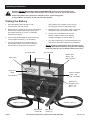
1
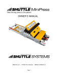
500 Amp Carbon Pile Load Tester Item 91129 500 AM CARBON P LOAD TE PILE STER Testing Capability Load Test Capacity Display Meters Test Cycle Battery Cables 12 VDC Batteries, Alternators, 160 Ah; 1000 CCA and Starter max. testing Analog, s 0-16 ; 0-500A load 15 second VDC (max.); Analog s , 0-500A 3 tests in per test with a 1 minute 5 minute cool down; s maxim 3’ x 4 AWG um with copper -plated clamps WARNING OFF To preven t serious injury and 1. Wear ANSI-a burns: heavy-duty pproved safety goggles work gloves during setup and 2. Do not touch and use. Vents get tester’s vents during VERY HOT or during use. after use. 3. Inspec t before every do not use use; if parts loose 4. Use as or damag ed. intended only. 5. Read manual before set up and/or use. LOAD 04b-11e Read this material before using this product. Failure to do so can result in serious injury. SAVE THIS MANUAL. ITEM 91129 Made in China. When unpacking, make sure that the product is intact and undamaged. If any parts are missing or broken, please call 1-800-444-3353 as soon as possible. Visit our website at: http://www.harborfreight.com Copyright© 2004 by Harbor Freight Tools®. All rights reserved. No portion of this manual or any artwork contained herein may be reproduced in any shape or form without the express written consent of Harbor Freight Tools. Diagrams within this manual may not be drawn proportionally. Due to continuing improvements, actual product may differ slightly from the product described herein. Tools required for assembly and service may not be included. Manual Revised 11e Save This Manual Keep this manual for the safety warnings and precautions, assembly, operating, inspection, maintenance and cleaning procedures. Write the product’s serial number in the back of the manual near the assembly diagram (or month and year of purchase if product has no number). Keep this manual and the receipt in a safe and dry place for future reference. Safety Alert Symbol and Signal Words In this manual, on the labeling, and all other information provided with this product: This is the safety alert symbol. It is used to alert you to potential personal injury hazards. Obey all safety messages that follow this symbol to avoid possible injury or death. DANGER indicates a hazardous situation which, if not avoided, will result in death or serious injury. CAUTION, used with the safety alert symbol, indicates a hazardous situation which, if not avoided, could result in minor or moderate injury. NOTICE is used to address practices not related to personal injury. CAUTION, without the safety alert symbol, is used to address practices not related to personal injury. WARNING indicates a hazardous situation which, if not avoided, could result in death or serious injury. IMPORTANT SAFETY INSTRUCTIONS INSTRUCTIONS PERTAINING TO A RISK OF FIRE, ELECTRIC SHOCK, OR INJURY TO PERSONS 6. Maintain this product. Check for breakage of parts and any other condition that may affect this product’s operation. If damaged, have the unit repaired before use. WARNING – When using tools, basic precautions should always be followed, including the following: 7. Use this product in accordance with these instructions, taking into account the working conditions and the work to be performed. Use of this product for operations different from those intended could result in a hazardous situation. 1. Wear ANSI-approved safety goggles during set up and use of the Load Tester. 2. Test in a well ventilated area. Explosive gases may be produced during testing. Do not smoke, cause sparks, or strike matches near the battery when testing. 3. Always refer to the user manual of the battery/ alternator being tested for testing instructions and precautions prior to using the Load Tester. 4. Do not reverse the polarity of the Battery & Alternator Tester’s Ring Terminals or vehicle battery. 5. Do not expose this product to rain or wet conditions. Page 2 8. This product is not a toy. Keep it out of reach of children. 9. Maintain labels and nameplates on the unit. These carry important safety information. If unreadable or missing, contact Harbor Freight Tools for a replacement. 10. People with pacemakers should consult their physician(s) before use. Electromagnetic fields in close proximity to heart pacemaker could cause pacemaker interference or pacemaker failure. Caution is necessary when near coil, spark plug cables, or distributor of running engine. Engine should be off during distributor adjustment. For technical questions, please call 1-800-444-3353. SKU 91129 Specific Safety Instructions 1. When connecting the Battery Cables to the battery, avoid creating sparks; especially when the battery is being charged. Explosive gases are created during charging. Sparking could also damage the vehicle electrical system. 2. Do not touch the cooling vents on the Load Tester during or immediately after testing the battery. They become very hot. terminal of the battery. Reversing Load Tester Cable Clamps on the battery will damage the tester. 5. Do not drop the Load Tester. 6. Do not smoke or have open flames near the battery. 7. Do not connect the Load Tester to the battery while the engine is running. Turn the engine off before connecting. 3. When placing the Load Tester in the vehicle’s engine compartment, take special care that the metal housing of the Tester does not come in contact with either terminal of the battery or other electrical connections. 4. Be certain of the test battery polarity before connecting the test Cable Clamps. The red Cable Clamp goes to the positive terminal of the battery. The black Cable Clamp goes to the negative 8. The warnings and precautions discussed in this manual cannot cover all possible conditions and situations that may occur. It must be understood by the operator that common sense and caution are factors which cannot be built into this product, but must be supplied by the operator. SAVE THESE INSTRUCTIONS. Specifications Testing Capability Load Test Capacity Display Meters Test Cycle Battery Cable / Clamps SKU 91129 12 VDC batteries, alternators, starters 160 amp hour Up to 1000 cold cranking amps 0 ~ 500A load Analog, 0 ~ 16 VDC (max.) Analog, 0 ~ 500A; 0 ~ 160Ah; 0 ~ 1000 CCA 15 seconds per test with 1 minute cool down 3 tests in 5 minutes maximum 3 FT. long; copper plated clamps; #4 AWG For technical questions, please call 1-800-444-3353. Page 3 Operating Instructions Read the ENTIRE IMPORTANT SAFETY INFORMATION section at the beginning of this manual including all text under subheadings therein before set up or use of this product. Inspect tool before use, looking for damaged, loose, and missing parts. If any problems are found, do not use tool until repaired. Testing the Battery 1. Wipe the battery terminals with a cloth to remove any dirt and grease. (Ah) capacity of the battery. The CCA and AH rating are printed on the battery label. 2. Make sure the Load Knob (C) is in the off position. Connect the red (positive) Cable Clamp (A) to the positive terminal (+) on the 12 V battery. See photo on page 4. 5. Maintain load for 15 seconds. After 15 seconds has passed, the unit will sound with a beep. 6. View the DC Volts Meter and read the battery condition. Refer to the “Battery Condition Analysis” section on page 5. 3. Connect the black (negative) Cable Clamp (B) to the negative terminal (–) on the battery. 7. Turn the Load Knob (C) counterclockwise to Off, and remove the Cable Clamps from the battery. 4. Turn the Load Knob (C) clockwise until the DC ammeter reads 1/2 the Cold Crank Amp (CCA) rating or three times the amp-hour NOTE: Freezing temperatures affect the battery test reading. Decrease the battery rating 50 cold cranking amps for each 50°F (10°C) below freezing 32°F (0°C). DC Amp Meter DC Volt Meter Battery Test: Green - OK Red - Replace Amp Scale Amp Hour Scale State of Charge: Green - OK Red - Recharge CCA Scale Load Knob (C) 500 AM CARBON P LOAD T PILE ESTER Testing Capabili ty Load Test Capacity Display Meters Test Cyc le Battery Cables 12 VDC Batterie s, Alternat 160 Ah; ors, and 1000 CCA Starters max. test Analog, ing; 0-50 0-16 0A load 15 seconds VDC (max.); Ana log, 0-50 0A 3 tests in per test with a 1 minute 5 minutes cool dow maximu 3’ x 4 AWG n; m with cop per-plated clamps WARNING OFF Alternator & Regulator Test: Green - OK Red - Low To prevent serious injury and 1. Wear ANSI-ap burns: heavy-duty proved safety goggles work glov and es during 2. Do not setup and touch use. Vents get tester’s vents duri VERY HOT ng or during use after use. 3. Inspect . befo do not use re every use; if parts loos e or dam 4. Use as aged. intended only. 5. Read manual befo re set up and/or use . LOAD 04b-11e ITEM 911 29 Made in China. Positive Cable (-) Negative Cable (-) Black Cable (Clamp B) Page 4 Red Cable (Clamp A) For technical questions, please call 1-800-444-3353. SKU 91129 Testing the Charging System AVOID CARBON MONOXIDE POISONING. This gas comes from the vehicle’s exhaust and is colorless and odorless. It can cause SERIOUS INJURY or DEATH if inhaled. 1. Turn the Load Knob (C) counterclockwise to the Off position. 2. Connect the Cable Clamps to the battery as previously described. 3. Outside, or in a well ventilated area, start the vehicle engine and run at fast idle speed. 4. View the DC Volt Meter and read the Alt. - Reg. condition. Refer to the “Battery Condition Analysis” section. 5. Turn the vehicle’s engine off, then remove the Load Tester Cable Clamps. Battery Condition Analysis Load Test / 15 Seconds (Display Reading) OK (Green Area) Bad (Red Area) Charging System (Alt. & Reg Test) Battery Condition Battery capacity is good. May or may not be fully charged. Check the charge state by testing the Specific Gravity (SG) with a Hydrometer. If SG is less than full charge, check for possible charging system trouble. Recharge to full level. If the DC Volt Meter needle is falling, the battery is defective or has a bad cell. For a quick check, turn the Load Knob down, counterclockwise, and note DC Volt Meter reaction. If voltage recovers to its full potential after only a few seconds, the battery is probably defective. If the voltage recovers slowly, the battery may only be run down. Check specific gravity level, recharge and re-test. If the DC Volt Meter needle reads OK, charging system is functional. If it falls on the low red or high red areas, charging system may be malfunctioning. Starter Motor Test NOTE: If starting your vehicle is difficult, you may have unnecessary starter motor draw, which dramatically shortens battery life. This test identifies starter motor performance. 1. Make sure your engine is running at normal operating temperature, and that the battery is fully charged and in good condition. 2. Turn the Load Knob (C) counterclockwise to the Off position. 3. Connect the Red Clamp (+) to the positive (+) terminal post on the battery. Connect the Black Clamp (-) to the negative (-) terminal post on the battery. 4. Disable the engine to make sure the car will not start. Refer to your vehicle’s service / technical manual. SKU 91129 5. While watching the DC Volt Meter (see page 4), crank the engine briefly to determine the voltage reading during cranking. A display reading of 9 volts or less indicates excessive current draw. This may be caused by a bad connection of a failing starter motor, or, the battery is too small for the vehicle’s requirements. Consult a qualified mechanic. 6. When starter motor test is complete, remove Black Clamp (-) from battery first; then remove Red (+) clamp. For technical questions, please call 1-800-444-3353. Page 5 User‑Maintenance Instructions Procedures not specifically explained in this manual must be performed only by a qualified technician. TO PREVENT SERIOUS INJURY FROM ACCIDENTAL OPERATION: Do not use damaged equipment. If abnormal noise or vibration, occurs, have the problem corrected before further use. Note: These procedures are in addition to the regular checks and maintenance explained as part of the regular operation of the air-operated tool. 1. Periodically check all nuts, bolts, and screws for tightness. 2. Store in a clean, dry location. 3. Clean the outside of the unit with a damp cloth. Never use solvents to clean any parts of this tool. Allow tool to dry completely before use. 4. Use compressed air to blow out debris from the load vents. 5. After each use, clean the Cable Clamps of any possible battery electrolyte. Apply a thin coat of silicon grease to prevent corrosion. Record Product’s Serial Number Here: Note: If product has no serial number, record month and year of purchase instead. Replacement parts are not available for this item. Page 6 For technical questions, please call 1-800-444-3353. SKU 91129 90 Day Warranty Harbor Freight Tools Co. makes every effort to assure that its products meet high quality and durability standards, and warrants to the original purchaser that this product is free from defects in materials and workmanship for the period of 90 days from the date of purchase. This warranty does not apply to damage due directly or indirectly, to misuse, abuse, negligence or accidents, repairs or alterations outside our facilities, criminal activity, improper installation, normal wear and tear, or to lack of maintenance. We shall in no event be liable for death, injuries to persons or property, or for incidental, contingent, special or consequential damages arising from the use of our product. Some states do not allow the exclusion or limitation of incidental or consequential damages, so the above limitation of exclusion may not apply to you. THIS WARRANTY IS EXPRESSLY IN LIEU OF ALL OTHER WARRANTIES, SKU 91129 EXPRESS OR IMPLIED, INCLUDING THE WARRANTIES OF MERCHANTABILITY AND FITNESS. To take advantage of this warranty, the product or part must be returned to us with transportation charges prepaid. Proof of purchase date and an explanation of the complaint must accompany the merchandise. If our inspection verifies the defect, we will either repair or replace the product at our election or we may elect to refund the purchase price if we cannot readily and quickly provide you with a replacement. We will return repaired products at our expense, but if we determine there is no defect, or that the defect resulted from causes not within the scope of our warranty, then you must bear the cost of returning the product. This warranty gives you specific legal rights and you may also have other rights which vary from state to state. For technical questions, please call 1-800-444-3353. Page 7 3491 Mission Oaks Blvd. • PO Box 6009 • Camarillo, CA 93011 • (800) 444-3353