1
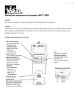
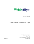
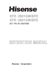
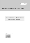
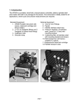
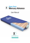
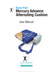
711 Charger
Service Manual
711 UNIVERSAL DESK CHARGER
711380
Rev. D
Welch Allyn Medical Division
4341 State Street Road
P.O. Box 220
Skaneateles Falls, NY 13153-0220
Copyright 2001
D escri pti on
EC N #
D ate
A pproved
711380
A
New Release of Uni versal C harger
S ervi ce Manual
5-43820
10/09/01
DK
711380
B
Update per E C N
5-43926
11/09/01
711380
C
Update per E C N
5-44417
03/12/02
DK
711380
D
Update per E C N
5-44590
05/06/02
DK
P art N o
R ev
DK
Drawings and/or illustrations and/or part numbers contained in this document
are for reference purposes only. For current revisions call the Welch Allyn
Customer Service phone number listed in Section 1 page 3.
SERVICE MANUAL 711380 REV. D
WELCH ALLYN UNIVERSAL DESK CHARGER i
Contents
PAGE
Section 1: General Information
1.1 About the Universal Desk Charger ............................................................................... 1
1.2 Block Diagram ............................................................................................................. 1
1.3 Hardware Electrical Specifications ............................................ ...................................... 2
1.4 Help Information ............................................................................................................ 3
1.5 Product Number Structure ............................................................................................. 3
1.6 Safety Warnings ........................................................................................................... 4
1.7 Approvals .................................................................................................................... 4
Section 2: Service
2.1 Incoming Inspection/Checklist ..................................................................................... 5
2.2 Required Tools............................................................................................................. 5
2.3 Incoming Operational Test ........................................................................................... 5
Section 3: Troubleshooting
3.1 Functional Tests/ Initial Diagnostic Steps ..................................................................... 6
Section 4: Repair and Disassembly
4.1.1 Base Housing Removal/Installation ............................................................................ 7
4.1.2 Printed Circuit Board Replacement ............................................................................ 7
4.1.3 Fuse Replacement .................................................................................................... 8
Appendix A: Theory of Operation..............................................................................................9
Appendix B: Assembly Drawing..............................................................................................13
Appendix C: Electrical Schematic..........................................................................................14
ii WELCH ALLYN UNIVERSAL DESK CHARGER
SERVICE MANUAL 711380 REV. D
The universal desk charger electrical circuitry is designed
to provide a safe (if not optimal) trickle charge profile for
all Welch Allyn handles. It is intended to replace the
71110 Desk Charger. However, the major improvements
over the 71110 that directly affect the electrical design
are:
1. It is intended to operate from an AC power source
from 100V to 275V. Along with a standard IEC
connector, this will be an international unit. Performance tests show that the charger will operate
down to 90V with a single handle receiving a full
charge rate (65 mA), and two handles receiving
>45 mA. This exceeds our present 71110 handle
which provides 20 – 30 mA under the same conditions.
1.1 About the 711
Universal Charger
IMPORTANT: for a complete
description on the function and
use of the 711 Universal Charger,
as well as user safety warnings,
cautions, and warranty information, read and understand the 711
Universal Charger Operator’s
Manual part number 711371
(English). Other languages are
available.
2. It is intentionally designed to charge handle /
battery combinations that range from 2.5V to 5.5V
end-of-charge voltages. Given the present high /
low line and high / low battery voltage combinations, the 71110 charger varies its charge current
from 20 mA to 80 mA. The universal desk charger
is designed to vary by less than 10% under these
conditions (typically less than 2%).
3. The universal desk charger provides charge
indicator LED’s as well as power on indicator
LED(s).
1.2 Block Diagram
Charging Well #1
AMBER LED
(on when current is active)
Current
Limit
Voltage
Limit
Output
P
O
W
E
R
I
N
P
U
T
Charging Well #2
AMBER LED
(on when current is active)
POWER
ON
LED
Current
Limit
SERVICE MANUAL 711380 REV. D
Voltage
Limit
Output
WELCH ALLYN UNIVERSAL DESK CHARGER 1
1.3 Hardware Electrical Specifications
1.3.1 Absolute Maximum Ratings
Input Voltage Range:
100VACRMS to 240VACRMS,
50Hz or 60HZ.
Peak Input Voltage:
275VACRMS (limited by
LM317T max voltage spec and
transformer design) It is only
guaranteed to maintain SELF
internal voltages up to 240V,
which is its highest rated input.
Output Voltage:
0V – Open Circuit Voltage
(Output may be dragged below
zero volts if input voltage is
less than the peak input voltage)
Output Current:
0 mA to +100 mA (internally
limited to 80 mA for short
circuit)
Operating Temperature:
5 - 35 Degrees Celsius *, 10%
- 90% Relative Humidity
Storage Temperature:
-20 - +50 Degrees Celsius *,
10% - 90% Relative Humidity
* This may not be a suitable range for the batteries under
charge.
1.3.2 Operating Conditions
Output Voltage:
<10VDC (no load)
Current Limit:
55 mA to 80 mA
Power Consumption
(No Load): 7W
Max (high line transformer
losses, no load)
Power Consumption (Full Load):10W Max (high line PCB
resistor, transistor, LED, and
LM317 at max Load)
Power Dissipation:
Internally Limited to 17W
(Assumes full transformer loss
at dual short circuit)
2
WELCH ALLYN UNIVERSAL DESK CHARGER
SERVICE MANUAL 711380 REV. D
All service and repairs must be performed by fully
trained and properly equipped personnel, using genuine replacement parts and correct procedures. Failure
to do so will invalidate the 1 year new product warranty.
1.4 Help Information
Customer Service
Welch Allyn, Inc.
4341 State Street Road, PO Box 220
Skaneatles Falls, NY 13153-0220 U.S.A.
Telephone 1-800-535-6663
When calling, refer to the model number on the
bottom of the Universal Charger.
The Model Number is the first three digits of the Serial
number found on the bottom of the Universal Charger.
Troubleshooting assistance is contained in Section 3 of
this manual to help determine which board is
malfunctioning. This manual does not support repairing
the printed circuit boards.
Year 2000 Information: The Universal Charger is Y2K
compliant and will not encounter “Year 2000” problem
71140
US, Canada, Japan Version
71142
European Version
71144
United Kingdom Version
71146
Australian Version
SERVICE MANUAL 711380 REV. D
1.5 Product Model
Number Structure
WELCH ALLYN UNIVERSAL DESK CHARGER 3
1.6 Safety Warnings
Read and understand all safety warnings and
service notes printed in this Service Manual and
the Operator’s Manual part number 711137.
Use hospital grade plugs only.
Green power light indicates that main power is
connected to the appliance.
Only authorized Welch Allyn Service Centers can
perform service.
This product complies with current required standards for electromagnetic interference and should
not present problems to other equipment nor is it
affected by other devices. As a precaution, avoid
using this device in close proximity to other equipment.
See User Manual or call Welch Allyn for the most
current approvals.
1.7 Approvals
C
US
UL 2601-1, CAN/CSA
C22.2 No 601.1, IEC
60601-1, IEC 60601-1-2
EMC Framework of Australia
The CE mark on this product indicates that it has been tested to and conforms
with the provisions noted within the 93/42/EEC Medical Device Directive.
Authorized European Representative Address:
European Regulatory Manager
Welch Allyn Ltd.,
Kells Road, Navan,
County Meath, Republic of Ireland.
Tel.: 353-46-79060 / Fax: 353-46-27128
4
WELCH ALLYN UNIVERSAL DESK CHARGER
SERVICE MANUAL 711380 REV. D
2.1.1 Inspect shipping package and product for
damage. Make a record of possible shipping
damage.
2.1
Incoming
Inspection
2.2.1 Tools required for service: Phillips screw driver,
repair test handle T17814.
2.2
Required Tools
2.3
Incoming
Operational Test
NOTE: Any Welch Allyn rechargable
handle can be substituted for the T17814
repair test handle.
2.2.2 The repair test handle, Tool# T17814, can be
ordered from Welch Allyn by calling Customer
Service at 800-535-6663.
2.1.1 Apply main power to the unit and ensure that the
green LED light illuminates.
With main power applied, insert any Welch Allyn
nicad handle into one of the charging wells and
ensure that the amber charge LED under that well
lights. Repeat the test on the opposite charging
well.
SERVICE MANUAL 711380 REV. D
WELCH ALLYN UNIVERSAL DESK CHARGER 5
3.1 Trouble Shooting
3.1.1 Green LED not on.
Use a known good power cord.
Replace the power cord if this fixes
the problem.
Check Fuses
If fuses are OK, then replace printed
circuit board.
3.1.2 Amber charge LED not on.
Insert a Welch Allyn rechargeable
handle in charging well or T17814
repair test handle. If the amber
charge light still does not come on,
then replace printed circuit board.
6
WELCH ALLYN UNIVERSAL DESK CHARGER
SERVICE MANUAL 711380 REV. D
4.1.1 Base Housing Removal/Installation
Removal
Remove the 4 screws holding the base housing to
the cover housing.
If a new base housing is required: Clean the
label and foot recesses on the new base housing
with isopropyl alcohol and allow them to dry. Install
a new model label in its recess as shown below.
4.1 Repair and
Disassembly
Observe all ESD precautions
Observe all ESD Precaution
Install 4 new feet in their corresponding recesses
Stamp the new base housing with the original date of
manufacture.
Installation
Place the base housing on top of the PCB (printed circuit
board) with the LED and IEC recesses lined up with
their respective components.
4.1.2 Printed circuit board replacement:
Remove base housing as described above.
Carefully lift printed circuit board up and out of the
cover housing.
Carefully place the new PCB into the cover housing.
Make sure the contacts are lined up with their
respective slots in the cover housing.
Make sure LEDs and IEC connectors are lined
up with their respective slots in the cover housing.
Reinstall base housing as described above.
SERVICE MANUAL 711380 REV. D
WELCH ALLYN UNIVERSAL DESK CHARGER 7
OBSERVE ALL ESD
PRECAUTIONS
4.1.3 Fuse Replacement:
Remove base housing as described above.
Remove PCB as described above.
Pry the two fuses out of the brackets on the IEC
connector that is attached to the PCB.
Insert the new fuses into the brackets on the IEC
connector.
Reinstall the PCB as described above.
Reinstall the base housing as described as above.
8
WELCH ALLYN UNIVERSAL DESK CHARGER
SERVICE MANUAL 711380 REV. D
APPENDIX A
Detailed Description Theory
Input
The Input provides a power entry module, transformer, bridge
rectifier, and sufficient bulk capacitance to assure 200 mA operation under low line conditions.
The full wave bridge consists of four 1N4004 rectifier diodes.
The bulk filter capacitor is 1000 uF, 50V. Since the rectified
voltage cannot exceed 40V (LM317 limitation), and the transformer cannot exceed 25VACRMS (per agency) the design has a
safe margin. Given the expected 200 mA constant current load,
the droop in 10 mS (50 Hz, full wave rectified) should be 2V per
half cycle.
Current Limit
The Current Limit limits the output current to 65 mA typical.
The current limit circuitry in its most basic form employs a LM317
adjustable voltage regulator and a current viewing resistor. The
resistor is placed between the adjust pin and the output pin. The
input to the current source is the Vin pin. The output is at the
adjust pin end of the viewing resistor as shown:
By design, a voltage regulator will shut down its output current as
the voltage between the output and the adjust pin approaches
regulator’s set voltage. (In the case of the LM317, the set
voltage is nominally 1.25V.) This condition gets satisfied when the
output current approaches 1.25V/Rlimit. Therefore, simply
picking the correct resistor value can choose any desired current .
SERVICE MANUAL 711380 REV. D
WELCH ALLYN UNIVERSAL DESK CHARGER 9
APPENDIX A
In the actual circuit, there is another resistor between The Output
and Adj. This is necessary for proper operation of the voltage
limit circuit, which will be discussed below. However, it should
be noted here that this resistor will have essentially no effect on
the operation of the basic current limit circuitry as described,
since the current out of the Adj pin is very low.
Transformer Headroom - The maximum trip point
(shutdown voltage) of the Simba handle is 5.06V. The current
limit circuit requires a maximum of 1.3V (across the sense
resistor) + the LM317 dropout voltage (1.6V @ 200 mA). This
requires 7.36V DC to guarantee 200 mA operation. Depending
upon the performance of the transformer, charging may take a
bit longer at low line. The low line tests have determined that the
charger will perform to nominal charge down to 100V input.
At 90V, a single handle will charge at its full rate, while two
handles will charge at about 45 mA each .
Voltage Limit
The Voltage Limit limits the output voltage to <8.78V. The
requirement is 9.5V in order to keep from biasing the input
protection Zener diode in the Simba Handle.
On its own, the simplified current limit circuit described above will
provide constant current from short circuit until the LM317 runs
out of headroom. This is great for charging the NiCad’s. However, the Simba handle eventually shuts down its charge when the
battery is fully charged. There is a 10V 1/2W input protection
Zener diode on the Simba handle, designed to protect the internal
circuitry from over voltage at the end of charge.
As mentioned in the discussion of the current limit circuit, the
LM317 adjustable regulator will shut down the output current as
the voltage between the output and the adjust pin approaches
1.25V. The voltage limit circuitry employs a 6.8V Zener diode
connected to the adjust pin on the LM317. This Zener limits the
adjust pin to 6.8V , which in turn prevents the output from nominally exceeding 6.8V +1.25V. As mentioned in the discussion of
the current limit circuit, there is a resistor between the adjust pin
and the current limit output. This limits the current through the
Zener diode when the circuit is in Voltage limit mode.
10
WELCH ALLYN UNIVERSAL DESK CHARGER
SERVICE MANUAL 711380 REV. D
APPENDIX A
LED
The LED section detects the current limit condition to indicate
that a charge is in process. This requires one Yellow LED per
charge well. There is also a green LED’s that simply indicate that
power is on.
Green Power On Indicator LED
The green LED is powered from a constant current source.
The constant current source uses three PNP transistors, two pass
transistors (required to handle worst case power) and one sense
transistor. The sense transistor limits the current by robbing the
pass transistors of their base bias. The sense transistor has its
emitter connected to +VRAW. There is a resistor between the
emitter and base of the sense transistor that provides a path for
the LED current. Whenever the LED current exceeds approximately 0.65V / Rsense, the sense transistor turns on. The collector of the sense transistor is tied to the bases of the pass transistors, which are normally pulled to ground (to turn on the pass
transistors). Hence, whenever the pass transistor begins to turn
on, the current is limited.
The pass transistors each have a 20 ohm resistor in series with
their base to avoid current “hogging” by one of the pass transistors should the pass transistor be mismatched. These resistors
typically drop only .13V .
Some of the older handles (still in the field) have no charge
polarity diodes installed. Since the LM317T’s used in the charging circuit are not reverse bias protected, the green “power on”
LED’s will be powered by one of these batteries, when the AC
power is disconnected. This could confuse someone to think that
their charger is connected to an AC source when it is not. Therefore, there are two diodes connected between the base of the
pass transistors (diode cathodes), with each anode connected to
one of the charging wells positive contacts. In this manner, should
either battery voltage ever exceed the raw DC voltage, the
corresponding diode will forward conduct, and the pass transistor
will not be biased (and the green “power on” LED’s will be shut
off).
SERVICE MANUAL 711380 REV. D
WELCH ALLYN UNIVERSAL DESK CHARGER 11
Yellow Charge indicator LEDs
Each yellow LED is meant to show that a particular well is
charging.
The yellow LED is on when the current limit is active. To do this,
the base – emitter junction of a PNP transistor is placed across
the battery charger current limit sense resistor. Whenever the
voltage drop across the current limit sense resistor exceeds .6V,
the transistor is turned on, and power is supplied to the LED.
Coincidentally, .6V is roughly ½ of the LM317 adjust voltage
(1.25V). Therefore, the LED starts conducting current when the
battery charge current is around ½ the current limit value. However, the LED becomes viewable at a somewhat higher charge
current.
Since the yellow LED receives its power on the high side of the
battery charger sense resistor, the LED current does not affect the
current limit to the battery.
12
WELCH ALLYN UNIVERSAL DESK CHARGER
SERVICE MANUAL 711380 REV. D
APPENDIX B
1
8
2
3
7
4
5
6
Ref
Part Number
1
711101-1
COVER, DESK CHARGER, PRINTED
2
711096-502
PC BOARD ASSY
3
711104
BASE, DESK CHARGER
4
495083
RUBBER FEET
5
711074
MDL LABEL,711 SERIES,DESK CHGR
6
106124-48
SCREW,#8 PLASTITE,.625L,PH
7
236706-3107
FUSE- INTERNATIONAL
8
761076-0
POWER CORD, DETACH.(DOM/JAPAN)
8
761076-2
POWER CORD-DETACH (EUROPEAN)
8
761076-4
POWER CORD-DETCHBL (U.K)
8
761076-6
POWER CORD DETACH (AUSTRALIA)
SERVICE MANUAL 711380
Description 71141
WELCH ALLYN UNIVERSAL DESK CHARGER 13
APPENDIX C
T RA NS FO R M E R , DE SK C H AR G ER
8
7
6
5
2
1
1
GND_POW ER
D2
1N4004
ACOUT2
2
J1
SCREW
2
3
1
C1
1 0 0 0 u F, 5 0 V
+
D4
1N4004
1
4
2
3
+V R A W
J2
SCREW
1
4
2
3
J3
SCREW
+V R AW
2
3
J4
SCREW
2
1
4
2
3
4
1
2
3
4
1
2
3
4
1
2
3
4
1
2
3
4
+V R AW
1
D3
1N4004
D1
1N4004
A C IN L E T, IE C 3 2 0 C O N N E C T O R
1
ACOUT1
2
F2
1 T1
2
3
4
1
F1
3 AC IN1
2 GND_ESD
1 AC IN2
2
PE1
R1
2 O N LED SE N SE
1
3
1
Q1
2N4403
1
1
4 9 .9
R4
20
R5
20
+C H A R G E 2
1
O NLED 2
O N LED C TL
2
2
Q2
2
Q3
2N4403
2
3
2N4403
3
2
D5
1N4004
1
ONLED1
1
1
D6
1N4004
2
2
+C H A R G E 1
O NLEDAN OD E
1
R2
1 0K
LED1
2
1
GREEN
D R AW N
PDL
A
REV
IN IT IA L R E L E A S E T O P R O D U CT IO N
R E V IS IO N D E S C R IP T IO N
ECN
PDL
1 -9 -0 1
IN I T
D AT E
D AT E
W elch A llyn
1 -9 -0 1
THESE DRAWINGS AND SPECIFICATIONS ARE THE PROPERTY OF WELCH ALLYN, INC.
AND SHALL NOT BE REPRODUCED, OR COPIED, OR USED AS A BASIS FOR SALE OR
MANUFACTURE OF EQUIPMENT OR DEVICES WITHOUT WRITTEN PERMISSION.
A P PR O VE D
RGA
D AT E
R E L T O P R O D U CT IO N
D AT E
T IT L E
<R E L_ DATE >
3 /1 5 /0 1
< R E L T O P R O D U C T IO N >
Size
A PP RV
C o p y rig h t
14 WELCH ALLYN UNIVERSAL DESK CHARGER
T h u rsd a y, M a rch 1 5 , 2 0 0 1
B
U n iv e rs a l C h a r g e r P C B
Rev
DWG NO
7 1111 8
Sh eet
1
of 1
X4
SERVICE MANUAL 711380
APPENDIX C
+V R AW
Q 11
2N4403
1
3
1
R 14
+ L E D 11
Y E LLO W 1
2
1
3 01
R 12
20
2
VO
TA B
VROUT1
2
4
1
VI
ADJ
U 11
LM 3 17
3
1
2
VRADJ1
2
R 11
3 01
2
L E D 11
YELLOW
LEDC TL1
2
2
R 13
1 50
1
1
1
2
3
1
2
3
2
J12
R V 11
TR AN SG UA R D , 18V
2
J13
C 11
0 .1 u F
1
2
3
1
2
3
J 11
C E N T E R C O N TA C T S P R IN G, P O S IT IV E
1
1
+CHARGE1
1
+CHARGE1
D 11
1 N 46 92 (6.8 v )
S I D E C O N TA C T S P R I N G, N E G A T I V E
+ V R AW
R 24
1
R 22
20
2
Y E LLO W 2
1
+LED2
3 01
2
VO
TA B
2
4
Q21
2N4403
1
3
1
VI
VROUT2
1
3
AD J
U 21
LM 3 17
1
2
VRADJ2
2
R 21
3 01
2
LED 21
YELLOW
LEDC TL2
2
2
R 23
1 50
1
1
C 21
0 .1 u F
RV21
TR AN SG UA R D , 18V
1
2
3
1
2
3
2
J22
2
1
2
3
J23
1
2
3
J21
C E N T E R C O N TA C T S P R IN G, P O S IT IV E
1
1
+CHARGE2
1
+C H A R G E 2
D 21
1 N 46 92 (6.8 v )
S I D E C O N TA C T S P R I N G, N E G A T I V E
D R AW N
PDL
A
R EV
IN IT IA L R ELE ASE TO PR O D U CT IO N
R EV ISIO N D ES C R IP T IO N
SERVICE MANUAL 711380
ECN
PDL
1-9-01
IN I T
D ATE
D ATE
W elch Allyn
1-9-01
THESE DRAWINGS AND SPECIFICATIONS ARE THE PROPERTY OF WELCH ALLYN, INC.
AND SHALL NOT BE REPRODUCED, OR COPIED, OR USED AS A BASIS FOR SALE OR
MANUFACTURE OF EQUIPMENT OR DEVICES WITHOUT WRITTEN PERMISSION.
AP PR O VED
RGA
D ATE
R EL TO P R O D U CT IO N
D ATE
TITLE
<R E L_D ATE >
3/15 /01
< R EL TO PR O D U C T IO N >
Size
A PP R V
C opy rig ht
T hursd ay, M arch 15, 2 001
B
U niv e rs al C ha rger P C B
R ev
DWG NO
711118
Sheet
1
of 1
X4
WELCH ALLYN UNIVERSAL DESK CHARGER 15