1
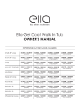
ELLA LOW THRESHOLD GEL COAT SHOWERS
OWNER'S MANUAL
REPRESENTING THESE MODEL NUMBERS:
3648 SH 1S 3P 4.0
Right Seat/Left Seat
4836 SH 4P 3.0
Center Drain
6032 SH 1S 3P 4.0
Right Seat/Left Seat
6033 SH 5P 4.0
Center Drain
6030 SH 5P 4.0
Right/Left Drain
Contents
Getting Started.................................................................................................................................... 1
Installation Procedure...................................................................................................................... 2-4
Limited Warranty................................................................................................................................. 5
Framing Dimensions............................................................................................................................ 6
Shower Diagrams................................................................................................................................ 7
Warranty Information......................................................................................................................... 8
Warranty Activation Form..............................................................................................................9-10
www.ellasbubbles.com
03/14
Getting Started
Thank you for purchasing an Ella Low Threshold Shower System. For best results, please read
and follow all directions carefully before beginning installation.
Tools/Materials you might need for proper installation:
•
•
•
•
•
6D Galvanized Screws
100% silicone caulking
Caulking gun
Acrylic latex caulk
Shims
•
•
•
•
•
Tape measure
1/8" drill bit
Phillips screw driver
Cardboard
China marker /
grease pencil
• Furring strips
• Construction adhesive
• Long spirit level
IMPORTANT! READ ALL INSTRUCTIONS
1. The back of a fiberglass unit is not waterproof. Unit must be stored so water will drain off
and not acumulate in one spot. Water can penetrate the back laminates and soak the
glassed in reinforcement supports causing bulges in the gelcoat unit.
2. Most handling damage is the result of impact blows to the back of hte fiberglass units.
3. Never drag a fiberglass unit on any surface. Always transport the unit y hand using (2)
people or two wheel dolly.
4. Never let a fiberglass unit drop from any height, not even an inch or stress cracks are likely
to occur.
5. Placing objects inside the unit can cause scratches or nicks to the surface. Do not use the
SECTIONAL
GELCOAT
BATHING
SYSTEMS
shower as a trash
receptacle! Always
place a drop
cloth or cardboard on the floor when
working inside the shower.
6. Never clean fiberglass gelcoat surface with metal tools of any kind, including razor blades.
ATION
CTIONS
on Planning
ONS COMPLETELY
NG INSTALLATION.
s out of doors.- Keep
d exposure to weather.
s 7, 8, and 9 to make
proper size. If a fire rated
pproved finish material must
unit installation. Access to
nections should be provided
tions may be made after the
led. Framing alcove must
sions on diagram to permit
ote in diagram the required
o provide clearance for the
ection.
e two wood shims (provided)
www.ellasbubbles.com
to provide
bottom structural
se unit.
See Figure 1.
rocedure
Figure 1
Wood Support Shims
Page 1wedges are in place
It is MANDATORY that these
and in proper contact to assure structural integrity
of the bathing unit.
03/14
Installation Procedure
1 of 3
1. Remove wall section(s) from the base unit. Carefully move all parts into the installation
area. Apply a bead of silicone to all joints. Reinstall wall sections. Align all parts, and connect
using the alignment pins. Wipe away any excess caulk that squeezes out. The unit will be
installed in the framed alcove as a one-piece unit. The unit must be installed completely
level.
Alternate Connection: If installing piece by piece into the alcove, make sure that the pins
are aligned correctly. When the caulking cures the parts are solidly held similar to the one
piece when attached to the framing. See Photo1. The valve wall should be the first wall
sections installed.
Photo 1
2. Drain and/or Overflow assembly should be installed on unit according to the
manufacturer’s instructions. Apply a bead of 100% silicone caulk around the drain opening in
unit before installing the fitting.
3. Locate supply lines for control valves and shower head. Measure and mark locations of
fittings on the finished side of the unit. Recheck locations, and drill 1/4" pilot holes. Cut holes
to final size using the appropriate size hole saw.
4. Apply wood wedges to the alcove floor. Carry unit to the opening. Align front of apron
to final location and tilt unit into place. Make certain that the wood shims contact both the
bathing unit and sub floor. Remove and adjust wedges if necessary to assure proper contact
for support.
It is MANDATORY that these wedges are in place and in proper contact to assure structural
integrity of the bathing unit.
5. Plumb and level the unit in two directions: Place a level on top of the apron, and along
the finished flat area at the top of the wall. Once the unit is leveled, if any gap appears
between the apron and sub floor fill the gap with solid material. When satisfied with the fit,
attach the unit to framing with 6d galvanized nails or screws through the pre-drilled holes in
the mounting flanges. If required, drill additional holes through the flanges in order to attach
the unit to each stud.
6. Make connections to supply and drain lines. Strap all lines to the framing. Install finish trim.
Caulk as necessary.
7. Check for leaks before installing wall-board and closing off plumbing access.
8. Finish wall board as detailed in Figure 2.
www.ellasbubbles.com
Page 2
03/14
Installation Procedure
2 of 3
8. Finish wall board as detailed in Figure 2.
Sectional bathing units are shipped from the factory with screws or nuts and bolts
connecting the parts together.
If installing the unit fastened together in one piece, follow instructions on Page 1 of this
manual.
The alignment pins should allow you to more easily install the unit in the framing alcove. Read
and understand the instructions on this page since the alignment pins must be inserted in a
specific direction.
1. Install drain and/or overflow assembly on unit following drain manufacturers instructions.
Place support wedges under the back edge and secure Place the base unit in the install
location. Level the unit. A minimum of two shims should be used for proper support. (See
Figure 5). Re-check level and attach base to framing studs with 6D galvanized screws.
SIDE VIEW
INTEGRAL SELF-LOCATING
METAL GUIDE PINS PAN
BASE DETAIL
INTEGRAL SELF-LOCATING
METAL GUIDE PIN DETAIL
2. Place a continuous bead of silicone on base between the edge of the base and the holes.
For three and four piece units, apply silicone up the vertical seam(s) at the front or inside
edge of the wall. Also around the pin alignment piece.
3. Place the walls on the top of the base aligning the holes with the pins. For three and four
piece units, install the left wall first. Repeating the same for the right wall. Press all seams
together to assure a tight fit. Wipe away any excess caulking. See Figure 5
4. For four piece units, install the back wall first. Install the left and right walls (Wet wall last).
Press the seams together, to assure a tight fit. Wipe away any excess caulking before it cures.
5. Make sure all seams are even and in alignment with the base section. Fasten the wall
assembly to the framing using 6D galvanized screws through the mounting flanges. Fasten
every 8" O.C. along the vertical flanges and to each framing stud along the top, horizontally.
www.ellasbubbles.com
Page 3
03/14
Place a continuous bead of silicone on
6. base
between the edge of the base and the holes
(As shown in Figure 4B). For three and four piece
units,apply silicone up the veritical seam(s) between
the holes for the fasteners and the front or inside edge
of the wall.
Installation Procedure
of blocks.
3 One
the walls on top of the3
wooden
7. Place
by one remove the blocks taking care to align the
6.
Make connections to
Figure 3
Caulk as necessary.
plastic fasteners into the holes in the underside of the
walls. For three piece units, install the left wall first.
Repeat for the right wall. Press all seams together to
assure a tight fit. wipe away any excess caulking.
supply
and
See Figure
5. drain lines. Strap all lines to the
framing. Install finish trim.
For four piece units, install the back wall first. Install
8. the
left and right walls, (Wet wall last.) Take care to
Fiberglass Unit
7. Check for leaks before align
installing
wall-board
closing
plumbing access.
the plastic
fasteners intoand
the holes
in the off
walls.
Silicone Bead
Finish
Plastic 8.
Fastener
Press the seams together, to assure a tight fit.
Wipe away
any excess
wall board as detailed
in Figure
6. caulking before it cures.
ece units, after applying the
head of the plastic fasteners for the
m the backside through the holes
on the left wall (the wall to the left
t) so they are facing the right and
are pressed firmly to the backside
, after applying the silicone to the
asteners for the walls, insert them
cal flanges of the back wall. These
rted from the backside and pressed
ad of the fasteners fully contact the
eners will be pointing out towards
ing unit.
nd/or overflow assembly on unit
n manufacturers instructions.
n the install location. Level the unit.
es under the back edge and secure
nimum of two shims should be used
See Figure 5). Re-check level and
ng studs with 6D galvanized screws.
Figure 5
Support Wedges
(Secure with adhesive)
2
CAUTION
If you use a RUBBER FLOOR MAT in this tub or shower unit it must be removed after each
usage. If left in the unit, it may cause blisters or damage to the surface finish.
DO NOT USE ABRASIVE CLEANERS
The most important caution is to avoid use of harsh abrasive cleaners or gritty scouring
powders. To clean the unit, simply use a household liquid detergent with soft sponge cloth
and warm water. More persistent stains, tar, or paint can be removed with naptha or mineral
spirits. Remove excess plaster by scraping with a sharpened soft wood stick. Avoid wire
brushes, metal scrapers or tools. Restore dull areas by rubbing with automotive type body
cleaning compound.
www.ellasbubbles.com
Page 4
03/14
Limited Warranty
LIMITED WARRANTY
Ella's Bubbles, LLC warrants to the owner of its Tub/Shower units as follows: Units
manufactured of fiberglass reinforced polyester resin, that it will, free of charge, repair
or exchange as its option, any Ella's Bubbles unit found to be defective in materials or
workmanship upon inspection by an authorized representative of Ella's Bubbles for a period
of three (3) years from date of purchase.
The exchange of a unit is limited to supplying a replacement unit of comparable size and
style and does not include any costs of removal or installation.
This warranty shall be voided if the unit is moved from its place of initial installation or is
not installed in accordance with the instructions supplied by the manufacturer of the unit.
Further, this warranty does not apply if the unit has been subjected to accident, abuse,
misuse, damage caused by flood, fire or act of God.
Since local code requirements vary greatly throughout the country, distributors, dealers,
installation contractors and users of plumbing products should determine whether
there are any code restrictions on the use of a specific product. Ella's Bubbles makes no
representation or warranty regarding and shall not be responsible for any code compliance.
The owner agrees by use of this unit that the obligations of Ella's Bubbles shall not exceed to
contingent or indirect damage or injury to the structure of its contents, that the obligations of
Ella's Bubbles are limited to those set forth herein, and that no other obligations, expressed or
implied, are assumed by Ella's Bubbles.
©2014, Ella's Bubbles, LLC
2101 S. Carpenter St., Chicago, IL 60808
1.800.480.0500
www.ellasbubbles.com
www.ellasbubbles.com
Page 5
03/14
Caulk
Gap
Mounting
Flange
Phone: (800) 443-7269
Fax:
(731) 925-7656
Framing Dimensions
FRAMING DIMENSIONS
Model No.
G 3838 NA 2P
Old No.
G 3838.51
G 6032 TS 2P
G 6030.74
G 3232 SH 2P
G 3232.50
G 3635 SH 2P
G 3635.53
G 4836 SH 2P 1S G 4835.54
G 3260 TS 3P
N/A
G 5494 TS 2P
Fig 5 Fig 7 Fig 6
N/A
X
X
A
79”
73”
X
X
74”
74”
74”
74”
74”
X
X
X
B
C
D
39-1/2” 39-1/2” 17-3/4”
60-1/4” 31-7/8” 14-3/4”
E
F
G
H
I
J
17-3/4”
17-3/4”
N/A
N/A
48”
27”
2-5/8”
14-3/4”
75”
81”
19”
42-1/4”
16-1/2”
16”
16-1/2”
76”
82”
48”
22”
18”
18”
48-1/4” 36-1/2”
16”
60-1/4” 32-3/4”
54-1/4” 27-1/2” 12-1/4”
48-1/4” 35-3/4” 18-1/4”
18”
24”
N/A
N/A
24”
18”
18”
16”
12-1/4”
76”
76”
N/A
N/A
82”
82”
N/A
N/A
48”
48”
N/A
N/A
22”
22”
N/A
N/A
N/A
N/A
N/A
N/A
18”
83-3/4” 83-3/4”
83-3/4” 83-3/4”
48”
22”
48”
22”
83-1/8” 83-1/8” 17-1/2”
43”
25-1/4” 38-1/4”
82”
79”
32-1/4” 33-1/2”
36-1/4” 36-1/2”
G 4887 SH 3P 1S
N/A
X
78”
G 3636.53
6839
X
36-1/4” 37-5/8” 16-1/8”
G 4834.50
X
73”
73”
48-1/4” 35-5/8” 16-3/8”
24”
16-1/8”
16-3/8”
1-3/8”
14-1/2”
G 4834 3P 2S
G 6030.75
6824/25
X
73”
60-1/4” 31-1/4” 14-1/2”
G 6036.71
6976/77
X
76”
G 6036.72
6880/81
N/A
N/A
X
X
81”
81”
78”
60-1/4”
60-1/4”
60-1/4”
48-1/4”
36-1/4”
36-1/4”
G 6017 TS 2P
G 4887 SH 2P 1S
X
N/A
X
X
G 3275 SH 2P
N/A
X
G 4080 NA 2P
N/A
G 3679 SH 3P
G 3687 SH 2P
N/A
78”
79”
77”
X
81”
32”
35-3/4”
15”
17-1/2”
37”
16”
37-3/4”
35-3/4” 18-1/4”
19”
37”
36-1/4” 17-1/2”
19-1/2”
34”
41-1/4” 41-1/4”
19”
18-1/4”
2”
15”
1-5/8”
N/A
24”
18”
18”
16”
17-1/2”
16”
18-1/4”
19”
19”
19”
81-1/4” 81-1/4”
N/A
N/A
N/A
N/A
N/A
N/A
N/A
17-1/2”
N/A
19-1/2” N/A
N/A
N/A
N/A
22”
N/A
N/A
N/A
42-1/2”
N/A
N/A
N/A
N/A
N/A
N/A
N/A
N/A
N/A
3
www.ellasbubbles.com
Page 6
03/14
Shower Diagrams
Sectional Gelcoat Showers
Sectional Gelcoat Tub/Showers
Required for
G 6036.72 Header for
Optional
111”
Dome
4
F
C
L Shower Head
and Fittings
13”
(optional)
13”
CL Shower Head
and Fittings
H
Blocking
(optional)
G
J
CL Fittings
CL Spout
F
H
Shower
Blocking
Header for
Optional Dome
J
C
L Shower
G
A
A
I
CLFittings
81/2”
I
E
E
D
C
CL
OUTLET
D
B
C
B
CL Outlet
Figure 7
Figure 8
G 3838 2P and G 4080 2P Showers
B
F
13”
CL Outlet and
Supply Fittings
Blocking
(optional)
J
CL Shower
CL Fittings
A
I
E
D
C
LIMITED WARRANTY
B
Figure 9
Praxis Companies warrants to the owner of its Tub/Shower units as follows:
Units manufactured of fiberglass reinforced polyester resin, that it will, free of charge, repair or exchange as its option, any Praxis Companies unit found to be defective
in materials or workmanship upon inspection by an authorized representitive of Praxis Companies for a period of three (3) years from date of purchase. The exchange
of a unit is limited to supplying a replacement unit of comparable size and style and does not include any costs of removal or installation.
This warranty shall be voided if the unit is moved from its place of initial installation or is not installed in accordance with the instructions supplied by the manufacturer
of the unit. Further, this warranty does not apply if the unit has been subjected to accident, abuse, misuse, damage caused by flood, fire or act of God.
www.ellasbubbles.com
Pageinstallation
7
Since local code requirements vary greatly throughout the country, distributers, dealers,
contractors and users of plumbing products should determine whether03/14
there are any code restrictions on the use of a specific product. Praxis Companies makes no representation or warranty regarding and shall not be responsible for
any code compliance.
The owner agrees by use of this unit that the obligations of Praxis Companies shall not exceed to contingent or indirect damage or injury to the structure of its contents,
that the obligations of Praxis Companies are limited to those set forth herin, and that no other obligations, expressed or implied, are assumed by Praxis Companies.
Ella’s Bubbles, LLC. warrants to the owner of its
ACCESSIBLE SHOWER IN A BOX as follows:
Units manufactured of fiberglass reinforced polyester resin, that it will, free of
charge, repair any Ella’s unit found to be defective in material or workmanship
upon inspection by an authorized representative of Ella’s for a period of thirty
(30) years from the date of purchase of the unit by a qualified professional.
The exchange of a unit is limited to supplying a replacement unit of
comparable size and style and does not include any cost of removal or
installation. Any component part supplied by Ella’s carries the same limited
warranty provided by our supplier for a period of one (1) year. Any Ella’s
product will carry a thirty (30) year limited warranty against manufacturing
defects. This warranty shall be voided if the unit is moved from its place of
initial installation or is not installed in accordance with the instructions
supplied by the manufacturer of the unit. Further, this warranty does not
apply if the unit has been subjected to accident, abuse, misuse, damage
caused by flood, fire, or act of God. The owner agrees by use of the unit that
the obligations of Ella’s Bubbles, LLC. shall not exceed to contingent or indirect
damage or injury to the structure of its contents, that the obligations of Ella
Walk in Baths are limited to those set forth herein, and that no other
obligations, expressed or implied, are assumed by Ella’s Bubbles.
All mailing notification must be sent via certified mail to:
Ella’s Bubbles, LLC.
2101 S. Carpenter Street
Chicago, IL 60608
Email: [email protected]
May 2013
TOLL FREE: 800-480-6850
Warranty Activation Form
1 of 2
INSTALLER'S INFORMATION
________________________________________________________________________________________
Name
________________________________________________________________________________________
Address
City
State
Zip
__________________________________ Telephone
__________________________________________________
Email
__________________________________ Date
__________________________________________________
Signature
Upon completing the installation of an Ella Walk In Tub, the following Warranty
Activation Form must be completed, signed by both the customer and installer, and
returned to Ella’s Bubbles, LLC. In order for the Warranty to be activated (faxed, scanned,
or emailed, or hard copy mailed).
To be initialed by the installer(s)
_____Tub is level in all directions and all support legs are touching the ground.
_____Tub is installed on a dedicated 30 Amp GFCI protected circuit using 10 gauge wire
_____Frame of the tub has been properly grounded.
_____Door Seal has been cleaning with rubbing alcohol to remove any dust or debris left
over from construction.
_____Temperature Control Valve operated on both hot and cold settings.
_____Both diverters function properly.
_____Hand Shower functions on all settings without leaking. _____All supply lines have been checked for leaks while both diverters are on.
_____Drains open and close properly, and the locking nut has been tightened on both
stoppers.
_____Door seal is water tight after tub has been filled for a minimum of 20 minutes.
_____After running for a minimum of 20 Minutes both the Hydro and Air Pumps are
functioning properly and all connections to the pumps and jets are water tight.
_____Chromatherapy Light and the Ozone Sterilization are working properly. (When the
Ozone is on by itself it will make a light humming noise).
_____All drain fittings have been checked for leaks while the tub is draining.
_____Unit is installed with access to both plumbing and electrical connections.
www.ellasbubbles.com
Page 23
03/14
Warranty Activation Form
2 of 2
OWNER'S INFORMATION
________________________________________________________________________________________
Name
________________________________________________________________________________________
Address
City
State
Zip
__________________________________ Telephone
__________________________________________________
Email
__________________________________ Date
__________________________________________________
Signature
Model: ____________________________________ Serial Number:_______________________________
Purchase Date:____________________________ Purchase Price:______________________________
Place of Purchase:______________________________________________________________________
Contact Name:____________________________ Phone Number:______________________________
Copy of sales receipt must be included
with warranty activation forms.
To activate manufacturer's warranty, please complete both pages and
use one of the options below to submit.
Via mail:
Ella's Bubbles, LLC.
Warranty Department
2101 S. Carpenter St., Chicago, IL 60608
Via fax:
1-312-666-3551
Via email:
[email protected]
www.ellasbubbles.com
Page 24
03/14