1
Basic 32
Loader Control
B32 Model
Installation
Operation
Maintenance
Troubleshooting
Instant Access
Parts and Service
(800) 458-1960
(814) 437-6861
www.conairnet.com
The Conair Group, Inc.
One Conair Drive
Pittsburgh, PA 15202
Phone: (412) 312-6000
Fax: (412)-312-6001
UGC007/0702
Please record your
equipment’s model and
serial number(s) and
the date you received it
in the spaces provided.
It’s a good idea to record the model, serial and software
version numbers of your equipment and the date you received
it in the User Guide. Our service department uses this information, along with the manual number, to provide help for the
specific equipment you installed.
Please keep this User Guide and all manuals, engineering
prints and parts lists together for documentation of your
equipment.
Date:
Manual Number:
UGC007/0702
Model number:
Serial number(s):
Software version number(s):
DISCLAIMER: The Conair Group shall not be liable for errors contained in this User Guide or for incidental, consequential damages
in connection with the furnishing, performance or use of this information. Conair makes no warranty of any kind with regard to this
information, including, but not limited to the implied warranties of
merchantability and fitness for a particular purpose.
Copyright 2002
THE CONAIR GROUP
All rights reserved
INTRODUCTION .........................................1-1
Purpose of the User Guide.....................................................1-2
How the Guide is Organized .................................................1-2
Your Responsibility as a User .............................................. 1-2
ATTENTION: Read this so no one gets hurt ........................1-3
TABLE OF
CONTENTS
DESCRIPTION . . . . . . . . . . . . . . . . . . . .2-1
What is the B32? . . . . . . . . . . . . . . . . . . . . . . . . . . . . . . . .2-2
Typical Applications . . . . . . . . . . . . . . . . . . . . . . . . . . . . .2-2
How it Works . . . . . . . . . . . . . . . . . . . . . . . . . . . . . . . . . . .2-3
Specifications . . . . . . . . . . . . . . . . . . . . . . . . . . . . . . . . . .2-4
INSTALLATION . . . . . . . . . . . . . . . . . . . .3-1
Unpacking the Boxes . . . . . . . . . . . . . . . . . . . . . . . . . . . . .3-2
Preparing for Installation . . . . . . . . . . . . . . . . . . . . . . . . . .3-3
Installing the B32 . . . . . . . . . . . . . . . . . . . . . . . . . . . . . . .3-4
Wiring Considerations . . . . . . . . . . . . . . . . . . . . . . . . . . . .3-4
Mounting the Control . . . . . . . . . . . . . . . . . . . . . . . . . . . . .3-5
Connecting to the B32 . . . . . . . . . . . . . . . . . . . . . . . . . . . .3-6
Wiring Loaders to the B32 . . . . . . . . . . . . . . . . . . . . . . . . .3-7
Wiring Pumps to the B32 . . . . . . . . . . . . . . . . . . . . . . . . . .3-7
Wiring Purge Valves to the B32 . . . . . . . . . . . . . . . . . . . . .3-7
Connecting Main Power to the B32 . . . . . . . . . . . . . . . . . .3-8
Initial Setup . . . . . . . . . . . . . . . . . . . . . . . . . . . . . . . . . . . .3-9
Setting Loader Parameters . . . . . . . . . . . . . . . . . . . . . . . .3-10
Enabling Loaders . . . . . . . . . . . . . . . . . . . . . . . . . . . . . . .3-11
Enabling Pumps . . . . . . . . . . . . . . . . . . . . . . . . . . . . . . . .3-11
Selecting a Password . . . . . . . . . . . . . . . . . . . . . . . . . . . .3-12
OPERATION . . . . . . . . . . . . . . . . . . . . . .4-1
B32 Control Features . . . . . . . . . . . . . . . . . . . . . . . . . . . . .4-2
Viewing Loader Status . . . . . . . . . . . . . . . . . . . . . . . . . . . .4-3
Enabling and Disabling Loaders . . . . . . . . . . . . . . . . . . . .4-4
Enabling and Disabling Pumps . . . . . . . . . . . . . . . . . . . . .4-5
Configuring Loaders . . . . . . . . . . . . . . . . . . . . . . . . . . . . .4-6
Assigning Pumps and Loaders . . . . . . . . . . . . . . . . . . . . . .4-7
Assigning a Backup Pump . . . . . . . . . . . . . . . . . . . . . . . . .4-8
Configuring the Alarm . . . . . . . . . . . . . . . . . . . . . . . . . . . .4-9
Backing up the PLC Program . . . . . . . . . . . . . . . . . . . . . .4-10
MAINTENANCE . . . . . . . . . . . . . . . . . . . .5-1
Preventive maintenance checklist . . . . . . . . . . . . . . . . . . . .5-2
UGC007/0702
Basic 32 Loader Control
i
TABLE OF
CONTENTS
TROUBLESHOOTING . . . . . . . . . . . . . . . .6-1
Before Beginning . . . . . . . . . . . . . . . . . . . . . . . . . . . . . . . .6-2
A Few Words of Caution . . . . . . . . . . . . . . . . . . . . . . . . . .6-2
Identifying the Cause of a Problem . . . . . . . . . . . . . . . . . .6-3
Clearing Interface Alarms . . . . . . . . . . . . . . . . . . . . . . . . .6-4
Clearing CPU and I/O alarms . . . . . . . . . . . . . . . . . . . . . .6-5
Conveying System Alarms . . . . . . . . . . . . . . . . . . . . . . . . .6-6
Operator Interface Problems . . . . . . . . . . . . . . . . . . . . . . .6-8
Processor and power problems . . . . . . . . . . . . . . . . . . . . . .6-8
CPU faults . . . . . . . . . . . . . . . . . . . . . . . . . . . . . . . . . . . . .6-9
I/O errors . . . . . . . . . . . . . . . . . . . . . . . . . . . . . . . . . . . . . .6-9
APPENDIX
Customer service information . . . . . . . . . . . . . . . . . . . . . .A-1
Warranty information . . . . . . . . . . . . . . . . . . . . . . . . . . . .A-2
Restoring the Program . . . . . . . . . . . . . . . . . . . . . . . . . . . .B-1
PARTS/DIAGRAMS
Wiring Diagrams
Recommended Spare Parts
ii
Basic 32 Loader Control
UGC007/0702
INTRODUCTION
l
l
l
l
UGC007/0702
Purpose of the User Guide .........1-2
How the guide is organized ........1-2
Your responsibilities as a user ...1-2
ATTENTION: Read this so
no one gets hurt .....................1-3
Basic 32 Loader Control
1-1
PURPOSE OF
THE USER
GUIDE
HOW THE
GUIDE IS
ORGANIZED
This User Guide describes the Conair Basic 32 Loader
Control and explains step-by-step how to install, operate,
maintain and repair this equipment.
Before installing this product, please take a few moments to
read the User Guide and review the diagrams and safety information in the instruction packet. You also should review manuals covering associated equipment in your system. This
review won’t take long, and it could save you valuable installation and operating time later.
Symbols have been used to help organize the User Guide and
call your attention to important information regarding safe
installation and operation.
Symbols within triangles warn of conditions that could
be hazardous to users or could damage equipment.
Read and take precautions before proceeding.
1
Numbers within shaded squares indicate tasks or steps
to be performed by the user.
diamond indicates the equipment’s response to an
u A
action performed by the user.
r
l
YOUR
RESPONSIBILITY
AS A USER
An open box marks items in a checklist.
A shaded circle marks items in a list.
You must be familiar with all safety procedures concerning
installation, operation and maintenance of this equipment.
Responsible safety procedures include:
l Thorough review of this User Guide, paying particular
attention to hazard warnings, appendices and related diagrams.
l Thorough review of the equipment itself, with careful
attention to voltage sources, intended use and warning
labels.
l Thorough review of instruction manuals for associated
equipment.
l Step-by-step adherence to instructions outlined in this
User Guide.
1-2
INTRODUCTION
Basic 32 Loader Control
UGC007/0702
We design equipment with the user’s safety in mind. You can
avoid the potential hazards identified on this machine by following the procedures outlined below and elsewhere in the
User Guide.
ATTENTION:
READ THIS SO
NO
ONE GETS HURT
WARNING: Improper installation, operation or servicing may result in equipment damage or personal injury.
This equipment should be installed, adjusted,
and serviced by qualified technical personnel
who are familiar with the construction, operation
and potential hazards of this type of equipment.
All wiring, disconnects and fuses should be
installed by qualified electrical technicians in
accordance with electrical codes in your region.
Always maintain a safe ground. Do not operate
the equipment at power levels other than what
is specified on the the equipment serial tag and
data plate.
WARNING: Electrical shock hazard
This equipment is powered by electrical voltage
as specified on the machine serial tag and data
plate.
A properly sized conductive ground wire from
the incoming power supply must be connected
to the chassis ground terminal inside the
Input/Output enclosure. Improper grounding can
result in personal injury and erratic machine
operation.
Always disconnect and lock out the incoming
main power source before opening the electrical
enclosure or performing non-standard operating
procedures such as troubleshooting or routine
maintenance. Only qualified personnel should
perform troubleshooting procedures requiring
access to the electrical enclosure while power
is on.
UGC007/0702
Basic 32 Loader Control
INTRODUCTION
1-3
DESCRIPTION
l What is the B32? . .
l Typical Applications
l How it Works . . . . .
l Specifications . . . .
UGC007/0702
.
.
.
.
.
.
.
.
.
.
.
.
.
.
.
.
.
.
.
.
.
.
.
.
.
.
.
.
Basic 32 Loader Control
.
.
.
.
.
.
.
.
.2-2
.2-2
.2-3
.2-4
2-1
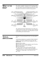
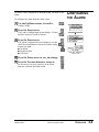
WHAT IS THE
B32?
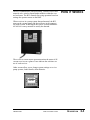
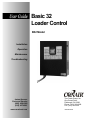
The control is mounted on the front of the I/O station. Inside
is a processor with base, containing up to 8 input/output modules. The number of input and output modules will vary with
the number of vacuum receivers and conveying options.
Pump
System 1
Pump
System 5
Pump
System 2
Pump
System 6
B32
Pump
System 3
Pump
System 7
Pump
System 4
Pump
System 8
Backup
Pump
The controller and control automatically turn on when power
is applied to the I/O station. After a bootup sequence the home
screen displays. From the home screen the operator can scroll
to all monitoring and control functions.
TYPICAL
APPLICATIONS
2-2
DESCRIPTION
The Basic 32 has been designed for basic conveying applications.
Loader-pump assignments are completely flexible. Individual
vacuum receivers can be assigned to any one of the eight
loading systems. Each receiver can be configured for one of
the following:
l Single-material loading.
l Ratio loading, with or without automatic material layering.
l Positive (air-operated) receiver discharge.
l Material line purging.
l Loader fill alarm to work with an optional fill sensor
mounted in the receiver body or direct feed chamber.
l Hopper fill alarm to work with an optional demand sensor
mounted in a drying hopper or other material vessel.
l No alarm.
Basic 32 Loader Control
UGC007/0702
The B32 communicates with each pump, vacuum receiver and
material valve wired to Input/Output modules within the control enclosure. The B32 controls conveying operation based on
settings the operator enters on the HMI.
HOW
IT
WORKS
When receivers in a pump system demand material, the B32
turns on the vacuum pump and dust collector in the appropriate pump system. It then opens the correct vacuum and material valves to convey material to satisfy the demand.
The overview screen lets the operator monitor the status of all
vacuum receivers at a glance. Icons indicate the real-time status of each receiver.
Other screens allow you to change system settings or to view
pump systems, loader details, alarm histories.
UGC007/0702
Basic 32 Loader Control
DESCRIPTION
2-3
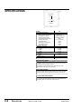
SPECIFICATIONS
C
3 inch screen
standard
A
5.5 inch screen
(optional)
B
MODEL
Performance characteristics
Maximum number of vacuum receivers
Maximum number of vacuum pumps
Programmable logic controller
Touchscreen operator interface
Communications with master control
Screen size, inches {mm}
User interface method
Output voltage to receivers/valves
Sensor voltage to receivers
Output voltage to pumps
Dimensions inches {mm}
Master control cabinet
A - Height
B - Width
C - Depth
Weight lb {kg}
Installed
Shipping
Voltages Total amps
115V/1 phase/60Hz (master control)
B32
32
8 (plus back-up)
Allen Bradley Micrologix 1500
Allen Bradley PV300 Micro
DH485
2.87 X 1.67 {73 X 42}
Keypad
24 VDC
24 VDC
24 VDC
31.4 {998}
23.8 {606}
12.5 {318}
70 {32}
85 {39}
10
SPECIFICATION NOTES:
B32 loader control cable: 18 gauge shielded, 8-conductor may be used
for standard vacuum receivers with up to one optional output and input,
otherwise 10-conductor cable is required.
Specifications can change without notice. Check with your Conair
representative for the most current information.
APPLICATION NOTES:
Conair vacuum receivers come equipped with a quick-disconnect connector set that includes 10 feet of cable. Junction boxes must be provided to
connect the system cable and each vacuum receiver’s connector set.
CALCULATING CABLE LENGTH:
Total the distances from the Input/output Station(s) location to each vacuum receiver on the system. Be sure to account for reasonable slack at
each loading station for connections, cable routing, etc.
2-4
DESCRIPTION
Basic 32 Loader Control
UGC007/0702
INSTALLATION
l Unpacking the Boxes . . . . . . . . . . .3-2
l Preparing for Installation . . . . . . . .3-3
l Installing the B32 . . . . . . . . . . . . . .3-4
l Wiring Considerations . . . . . . . . . .3-4
l Mounting the Control . . . . . . . . . .3-5
l Connecting to the B32 . . . . . . . . . .3-6
l Wiring Loaders to the B32 . . . . . . .3-7
l Wiring Pumps to the B32 . . . . . . . .3-7
l Wiring Purge Valves to the B32 . . .3-7
l Connecting Main Power . . . . . . . . .3-8
l Initial setup . . . . . . . . . . . . . . . . . . .3-9
l Setting Loader Parameters . . . . .3-10
l Enabling Loaders . . . . . . . . . . . . .3-11
l Enabling Pumps . . . . . . . . . . . . . .3-11
l Selecting a Password . . . . . . . . . .3-12
UGC007/0702
Basic 32 Loader Control
3-1
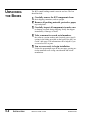
UNPACKING
THE BOXES
The B32 central loading control comes in one box. The box
should include:
1
Carefully remove the B32 components from
their shipping containers, and set upright.
2
Remove all packing material, protective paper,
tape and plastic.
3
Carefully inspect all components to make sure
no damage occurred during shipping. Notify the shipper
immediately if damage is found.
4
Take a moment to record serial numbers,
the software version number and electrical power specifications in the blanks provided on the back of the the User
Guide’s title page. The information will be helpful if you
ever need service or parts.
5
You are now ready to begin installation.
Follow the preparation steps on the next page, paying particular attention to all wiring consideration and recommendations.
3-2
INSTALLATION
Basic 32 Loader Control
UGC007/0702
You should plan the location of the B32 control to ensure easy
access and minimal wiring.
1
Select a mounting location for the control.
PREPARING FOR
INSTALLATION
The interface and Input/Output enclosure can be mounted
on a wall or other stable vertical surface.
Select a location that:
r Is central to loaders that the B32 will control. Keep
the B32 Input/Output station as close as possible to the
loading stations to minimize the amount of wire needed to
connect the vacuum receivers to the control.
r Provides adequate clearance for safe operation and
maintenance. The control should be mounted at a height
that allows the operator to easily see and touch the screen.
Maintain at least 3 feet (1m) clearance in front of the control for safe access to the Input/Output enclosure.
r Provides a clean, dry, vibration-free environment.
Exposure to wide temperature variations, high ambient
temperature, power line fluctuations, caustic fumes or
excessive amounts of dust, dirt, vibration, shock and
moisture could harm performance and reduce the life of
this equipment.
r Provides a grounded source of 115 VAC power.
The three-prong power cord supplied with the B32 control requires a grounded 115 VAC outlet rated for at least
15 amp service.
2
Plan the power/communication cable routes.
r Review all wiring guidelines and diagrams provided
in the manuals and electrical diagrams supplied with the
B32 control and your conveying equipment before beginning installation. See WIRING CONSIDERATIONS.
r Keep communication wires away from sources of
static electricity. Static electricity can damage the controls.Communication cables should not be run near the
material lines and hoses, which produce large amounts of
static electricity when material is conveyed. You should
use shielded cable unless you run wires through metal
conduit.
r Avoid running communication cables across power
feed lines. If you must run the cable across power feed
lines, run the cable at right angles to the lines.
UGC007/0702
Basic 32 Loader Control
INSTALLATION
3-3
INSTALLING
THE B32
WIRING
CONSIDERATIONS
3-4
INSTALLATION
Installation of the B32 control consists of:
r Mounting the enclosure.
r Wiring loaders to the control.
r Wiring pumps to the control.
r Wiring material valves to the control.
r Connecting the control to a main power source.
r Initial setup of the system control.
WARNING: Improper installation may
result in equipment damage or personal
injury.
● Disconnect and lock out the main power supply to
equipment in the conveying system before wiring
power and communication cables between the
B32 control, vacuum receivers, pumps, dust collectors and material valves.
● Install all wiring, disconnects and fuses in accordance with electrical codes in your region. All
electrical installations should be done only by
qualified electrical technicians.
● Always refer to the wiring diagrams supplied with
your control before making electrical connections.
The diagrams show the most accurate electrical
component information.
● Protect communication cables from sources of
static electricity and electrical noise.
● Use shielded cable or run wire through a contiguous metal conduit or wireway. Failure to use a
metal shield can expose the controls to static
electricity, which can damage electronic components.
● Do not run communication cables near material
lines and hoses, which produce large amounts of
static electricity when conveying material.
● Keep communication cables at least 5 ft. (1.5 m)
from electric motors, transformers, rectifiers, arc
welders, generators, induction furnaces and
sources microwave radiation.
● Avoid running communication cable across power
feed lines. If you must run cable across power
lines, run the cable at right angles to the line.
Keep the cable at least 6 inches (0.15 m) from AC
power lines of less than 20 A; 1 foot (0.30 m) from
lines of 20A to 100 kVA; and 2 feet (0.60 m) from
lines of 100 kVA or more.
Basic 32 Loader Control
UGC007/0702
WARNING: Improper installation may
result in equipment damage or personal
injury.
● Always maintain a safe ground. Follow the safe
grounding procedures in the wiring diagram package. Ground the shielded cable inside the
Input/Output enclosure only.
● Do not operate the equipment at power levels other
than those specified on the the equipment data
plate.
The B32 Input/Output enclosure should be
mounted on a wall, or other secure vertical
surface, at a height providing easy access
and a clear view of the touchscreen panel.
1
MOUNTING
THE CONTROL
Bolt the control to the
mounting surface. Use the mounting
brackets on the I/O enclosure.
2
Ground the control enclosure.
Connect a ground wire to the control. Follow procedures
outlined by your regional electrical codes and the wiring
diagrams included with this manual.
UGC007/0702
Basic 32 Loader Control
INSTALLATION
3-5
CONNECTING TO
THE B32
WARNING: Improper installation
may result in equipment damage or
personal injury.
Always refer to the wiring diagrams that came
with your controls before making electrical connections. The diagrams show the most accurate
electrical component information.
Use shielded cable unless you run wires in
metal conduit. Failure to use a metal shield will
expose the controls to static electricity, which
can damage electronic components.
When using shielded cable, make sure the
shield is grounded inside the I/O stations only.
It is also important to keep the communication
wires away from conveying lines, which can
produce large amounts of static electricity.
Each vacuum receiver, pump and
material valve in the system must be
wired to power or common/ground
terminals and Input/Output modules
inside the B32 control enclosure.
Input/Output modules
Each loader requires at least six
wire connections to the
Input/Output enclosure.
One additional wire is required for
each option or for a three-wire sensor used for either demand
or loader full inputs. Connect the loader cable wires to the I/O
station according to the color codes:
3-6
INSTALLATION
Basic 32 Loader Control
UGC007/0702
The loader wires connect to power terminals or terminals on
the I/O modules inside the control enclosure. The number of
loaders and options in the conveying system will determine
the number of connections that are required.
Refer to the electrical prints included with this manual for all
electrical connections to the loader control. All loader outputs
are 24 VDC and all demand and fill sensor inputs are 24
VDC.
A general list of loader electrical connections is included in
the appendix.
WIRING LOADERS
TO THE B32
IMPORTANT: Always refer
to the wiring diagrams that
came with your controls
before making electrical
connections. The diagrams
show the most accurate
electrical component information.
The B32 can run eight vacuum pumps and one backup pump.
Refer to the electrical prints included with this manual for all
electrical connections to the loader control. All pump outputs
are 24 VDC and all overload inputs are 24 VDC.
WIRING PUMPS
TO THE B32
The B32 can operate up to 32 purge valves, which are used to
remove material from the lines at the end of a loading cycle.
Since purge valves are located at the material source instead
of at the loader, separate wiring connections to the B32 are
required.
WIRING PURGE
VALVES TO THE
B32
(OPTIONAL)
UGC007/0702
Basic 32 Loader Control
INSTALLATION
3-7
CONNECTING
MAIN POWER
TO THE B32
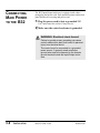
The B32 Input/Output enclosure is equipped with a threeprong plug and power cord. Each optional remote touchscreen
panel also has its own plug and power cord.
1 Plug the power cord(s) into a grounded 115
VAC outlet rated for at least 15 Amp service.
2 Make sure the control enclosure is grounded.
WARNING: Electrical shock hazard
Failure to provide proper grounding can cause
control malfunctions and could result in personal
injury from electrical shock.
The control must be connected to a grounded
power source. A properly sized conductive
ground wire must be connected to the chassis
ground terminal inside the Input/Output enclosure.
3-8
INSTALLATION
Basic 32 Loader Control
UGC007/0702
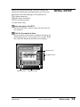
Before you can begin conveying, you must configure and
identify the loaders and conveying features you want to use.
INITIAL SETUP
Procedures on the following pages will explain how to:
r Set loader parameters
r Enable pumps and loaders
r Select security password
To begin Initial Setup:
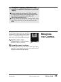
1 Turn on power to the B32.
The Power ON/OFF switch is on the left side of the control enclosure.
2 Wait for the control to boot.
Do not touch the control until it completes the bootup and
initialization process. Process takes a few seconds. When
the control has initialized, the Main Screen displays.
Display screen
Navigation arrows
Selection arrows
UGC007/0702
Navigation buttons
Basic 32 Loader Control
INSTALLATION
3-9
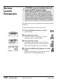
SETTING
LOADER
PARAMETERS
CAUTION: Incorrect configurations will
cause the B32 control to stop.
Before enabling loaders and loading functions,
make sure the loader, valve or option has been
installed in the system. Each loader and feature
must be wired to a correctly installed and enabled
input or output module. The B32 will fault and the
loading control will stop if the required I/O module
has not been installed for the feature you enabled.
The loader must be correctly installed and wired before setting
parameters.
To set loader parameters from the main screen:
1
Use the Up/Down arrows to scroll to
Loader Settings.
2
Press the Enter arrow.
The Loader Settings screen displays. Use the
up/down arrows to scroll to Settings.
3
Press the Enter arrow.
The Settings screen displays. Use the left/right
arrows to scroll to move the cursor to the Loader
field. Use the up/down arrows to select loader.
4
Use the Scroll Down/Up buttons to set the
loader
parameters: loader number, virgin time in seconds,
dump time in seconds and pump number.
3-10
INSTALLATION
Basic 32 Loader Control
UGC007/0702
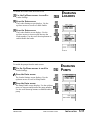
To enable the loaders from the main screen:
1
Use the Up/Down arrows to scroll to
Loader Settings.
2
ENABLING
LOADERS
Press the Enter arrow.
The Loader Settings screen displays. Use the
up/down arrows to scroll to Loader Enable.
3
Press the Enter arrow.
The Loader Enable screen displays. Use the
up/down arrows to increase and decrease the
loader number. Use the scroll down/up buttons to
enable/disable the loader.
To enable the pumps from the main screen:
1 Use the Up/Down arrows to scroll to
Loader Settings.
ENABLING
PUMPS
2 Press the Enter arrow.
The Loader Settings screen displays. Use the
up/down arrows to scroll to Pump Enable.
3 Press the Enter arrow.
The Pump Enable screen displays. Use the up/down
arrows to increase and decrease the pump number.
Use the scroll down/up buttons to enable/disable the
pump.
UGC007/0702
Basic 32 Loader Control
INSTALLATION
3-11
SELECTING A
PASSWORD
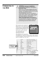
The B32 provides password security to prevent unauthorized
changes to loader or system settings.
1
Use the Up/Down arrows to scroll to
System Config. Entering the System Configuration
screen requires a Supervisor 2 password.
2
Enter the password.
To enter the password use the up/down arrows to
scroll through the alphanumeric list. When the correct letter/number is highlighted use the right Select arrow
to move to the next digit. Continue until the whole password is selected. The initial passwords are set at the factory:
● Supervisor 1: 7373
● Supervisor 2: 54647
Change these passwords and record the new passwords in
a safe place.
3
Press the Enter arrow.
The Factory Configuration screen displays. Use the
scroll up/down buttons to scroll to the New field.
Use the up/down arrows to scroll through the alphanumeric list. When the correct letter/number is highlighted
use the right Select arrow to move to the next digit.
Continue until the whole password is selected.
4
Press the Enter arrow.
The Password Administration screen displays. Use
the up/down arrows to scroll through the alphanumeric list. When the correct letter/number is highlighted
use the right Select arrow to move to the next digit.
Continue until the whole password is selected.
5
Press the Enter arrow to accept the
password.
6
Press the Main button to return to the
main screen.
3-12
INSTALLATION
Basic 32 Loader Control
UGC007/0702
OPERATION
l B32 Control Features . . . . . . . . . . .4-2
l Viewing Loader Status . . . . . . . . . .4-3
l Enabling and Disabling
Loaders . . . . . . . . . . . . . . . . . . . . .4-4
l Enabling and Disabling
Pumps . . . . . . . . . . . . . . . . . . . . .4-5
l Configuring Loaders . . . . . . . . . . .4-6
l Assigning Pumps and Loaders . . .4-7
l Assigning a Backup Pump . . . . . .4-8
l Configuring the Alarm . . . . . . . . . .4-9
l Backing up PLC Program . . . . . .4-10
UGC007/0702
Basic 32 Loader Control
4-1
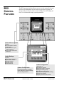
The B32 operator interface allows you to view the status of the vacuum receivers and pumps in your conveying system at a glance. It
also provides access to screens to enter settings for each loading station, view alarms and change system parameters.
B32
CONTROL
FEATURES
Quick-reference guides
Scroll to:
● Enable/disable loaders
and pumps
● Set load times, layers
and dump times
● View loader status and
alarm list
Loader Settings
Scroll to:
● Set loader parameters
● View loader status
● Enable loaders
● Enable pumps
● View alarm list
Loader Configuration
System Configuration
Prevent accidental or unauthorized changes to system settings
with security password.
4-2
OPERATION
Basic 32 Loader Control
Allows you to:
● Configure a loader
● Assign a loader to a pump
● Assign a backup pump
● Configure loader alarms
● Backup PLC program and settings
● Restore a program
● Display and clear PLC errors
UGC007/0702
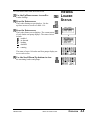
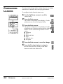
To view loader status from the main screen:
1
Use the Up/Down arrows to scroll to
Loader Settings.
2
Press the Enter arrow.
VIEWING
LOADER
STATUS
The Loader Settings screen displays. Use the
up/down arrows to scroll to Loader 1-16.
3
Press the Enter arrow.
The Loader Status screen displays. The current status
of each loader and pump displays. The status choices
include:
E - enabled
D - in demand
L - loading
E - disabled
R - running
The status of up to 16 loaders and four pumps display status on each screen.
4
Use the Scroll Down/Up buttons to view
the remaining loaders and pumps.
UGC007/0702
Basic 32 Loader Control
OPERATION
4-3
ENABLING
AND DISABLING
LOADERS
WARNING: Develop and follow procedures
for safe operation of the system to avoid possible injury or equipment damage.
The B32 allows operators and maintenance
personnel to disable and enable conveying system
components from remote locations. Unexpected
energization of these components could result in
equipment damage or injury.
Safe operating procedures should include:
r Disconnect any loader, pump or material
valve from main power and/or compressed air
sources before servicing. Ensure that all energy
sources for the device are locked out and
tagged.
r Before removing lockout devices or enabling
pumps, loaders or material valves, make sure
that all personnel are clear of the machine,
tools have been removed and any safety guards
have been reinstalled.
To enable the loaders from the main screen:
1
Use the Up/Down arrows to scroll to
Loader Settings.
2
Press the Enter arrow.
The Loader Settings screen displays. Use the
up/down arrows to scroll to Loader Enable.
3
Press the Enter arrow.
The Loader Enable screen displays. Use the
up/down arrows to increase and decrease the
loader number. Use the Scroll Down/Up buttons to
enable/disable the loader.
4
Press the Enter arrow to save the change.
5
Press the Previous button to return to
the last screen you were viewing, or the Main
button to return to the Main screen.
4-4
OPERATION
Basic 32 Loader Control
UGC007/0702
WARNING: Develop and follow procedures
for safe operation of the system to avoid possible injury or equipment damage.
The B32 allows operators and maintenance
personnel to disable and enable conveying system
components from remote locations. Unexpected
energization of these components could result in
equipment damage or injury.
ENABLING
AND DISABLING
PUMPS
Safe operating procedures should include:
r Disconnect any loader, pump or material
valve from main power and/or compressed air
sources before servicing. Ensure that all energy
sources for the device are locked out and
tagged.
r Before removing lockout devices or enabling
pumps, loaders or material valves, make sure
that all personnel are clear of the machine,
tools have been removed and any safety guards
have been reinstalled.
To enable the pumps from the main screen:
1
Use the Up/Down arrows to scroll to
Loader Settings.
2
Press the Enter arrow.
The Loader Settings screen displays. Use the
up/down arrows to scroll to Pump Enable.
3
Press the Enter arrow.
The Pump Enable screen displays. Use the up/down
arrows to increase and decrease the pump number.
Use the scroll down/up buttons to enable/disable
the pump.
NOTE: When a pump is disabled the loader completes its
load cycle before the pump is de-energized.
4
Press the Enter arrow to save the change.
5
Press the Previous button to return to
the last screen you were viewing, or the Main
button to return to the Main screen.
UGC007/0702
Basic 32 Loader Control
OPERATION
4-5
CONFIGURING
LOADERS
You may need to change loader settings whenever you change
materials or to obtain the best conveying performance.
To configure loaders from the main screen:
1
Use the Up/Down arrows to scroll to
Loader Config.
2
Press the Enter arrow.
The Loader Configuration screen displays. Use the
up/down arrows to scroll to Option Config.
3
Press the Enter arrow.
The Option Configuration screen displays. Use the
up/down arrows to increase and decrease the loader
number. Use the scroll down/up buttons to select
option:
● Discharge
● Ratio
● Ratio with Calc
● Purge
● Material valve
● No option
4
Press the Enter arrow to save the change.
5
Press the Previous button to return to
the last screen you were viewing, or the Main
button to return to the Main screen.
4-6
OPERATION
Basic 32 Loader Control
UGC007/0702
You may need to change loader and pump assignments to
match the conveying system vacuum and XXXX
To assign loaders and pumps from the main screen:
1
Use the Up/Down arrows to scroll to
ASSIGNING
LOADERS AND
PUMPS
Loader Config.
2
Press the Enter arrow.
The Loader Configuration screen displays. Use
the up/down arrows to scroll to Pump Assign.
3
Press the Enter arrow.
The Pump Assignment screen displays. Use the
up/down arrows to choose the loader number.
Use the scroll down/up buttons to choose the
pump number.
4
Press the Enter arrow to save the change.
5
Press the Previous button to return to
the last screen you were viewing, or the Main
button to return to the Main screen.
UGC007/0702
Basic 32 Loader Control
OPERATION
4-7
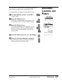
ASSIGNING A
BACKUP PUMP
A backup pump can be assigned to replace any of the eight
pump systems during operation.
To assign a backup pump:
1
Use the Up/Down arrows to scroll to
Loader Config.
2
Press the Enter arrow.
The Loader Configuration screen displays. Use the
up/down arrows to scroll to VP Back-Up Select.
3
Press the Enter arrow.
The Pump Back-up Select screen displays. Use the
scroll down/up buttons to select a backup pump
(pumps 1 through 8) or no backup pump.
4
Press the Enter arrow to save the change.
5
Press the Previous button to return to
the last screen you were viewing, or the Main
button to return to the Main screen.
4-8
OPERATION
Basic 32 Loader Control
UGC007/0702
Te loader can be configured for demand alarm, fill alarm or no
alarm.
To configure the alarm from the main screen:
1
CONFIGURING
THE ALARM
Use the Up/Down arrows to scroll to
Loader Config.
2
Press the Enter arrow.
The Loader Configuration screen displays. Use the
up/down arrows to scroll to Alarms.
3
Press the Enter arrow.
The Alarm Configuration screen displays. Use the
scroll down/up buttons to choose the alarm configuration you want:
● No alarm
● Demand alarm
● Fill alarm
4
Press the Enter arrow to save the change.
5
Press the Previous button to return to
the last screen you were viewing, or the Main
button to return to the Main screen.
UGC007/0702
Basic 32 Loader Control
OPERATION
4-9
BACKING UP
PLC PROGRAM
(OPTIONAL)
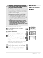
To back up the PLC program and save the configuration:
1
Use the Up/Down arrows to scroll to
Loader Config.
2
Press the Enter arrow.
The Loader Configuration screen displays. Use
the up/down arrows to scroll to Save Config.
3
Press the Enter arrow.
The Save Configuration screen displays. Use the
up/down arrows to scroll to Program Mode
4
Press the Enter arrow.
The Program Mode screen displays. Use the
up/down arrows to to select Save to EEPROM.
The screen displays message when transfer is
complete.
5
Use the Up/Down arrows to select
Run Mode.
NOTE: All pumps must be disabled to save the configuration. This insures that all putputs are turned off.
6
Press the Enter arrow to save the change.
7
Press the Previous button to return to
the last screen you were viewing, or the Main
button to return to the Main screen.
4-10
OPERATION
Basic 32 Loader Control
UGC007/0702
MAINTENANCE
l Maintenance checklist . . . . . . . .5-2
UGC007/0702
Basic 32 Loader Control
5-1
PREVENTIVE
MAINTENANCE
CHECKLIST
You should develop a preventive maintenance schedule for all
components in the conveying system to ensure optimum
operation and performance.
The B32 may require the following maintenance checks:
l Whenever you change materials
r Verify the loader settings for pump systems or loaders
effected by the material change. Pay particular attention
to load times and dump times. See CHANGING LOADER
SETTINGS in the Operation section.
l Quarterly
r Check power and cable connections and wires.
Over time, the power and cable connections between
the B32 and conveying system components may
become loose or wires may become worn. Tighten any
loose connections and replace any wire or cable that has
become worn or damaged.
5-2
MAINTENANCE
Basic 32 Loader Control
UGC007/0702
TROUBLESHOOTING
l Before Beginning . . . . . . . . . . . .6-2
l A Few Words of Caution . . . . . .6-2
l Identifying the Cause
of a Problem . . . . . . . . . . . . . . .6-3
l Clearing Interface Alarms . . . . .6-4
l Clearing CPU and I/O alarms . . .6-5
l Conveying System alarms . . . . .6-6
l Operator Interface
Problems . . . . . . . . . . . . . . . . .6-8
l Processor and Power
Problems. . . . . . . . . . . . . . . . . 6-8
l CPU faults . . . . . . . . . . . . . . . . .6-9
l I/O errors . . . . . . . . . . . . . . . . . .6-9
UGC007/0702
Basic 32 Loader Control
6-1
BEFORE
BEGINNING
A FEW WORDS
OF CAUTION
Before you begin troubleshooting:
o Find the manuals and wiring diagrams that
were shipped with your equipment.
These materials contain details you will need to diagnose and
repair problems in specific components, including custom
wiring, features or I/O options not covered in this User Guide.
WARNING: Improper installation, operation or servicing may result in equipment damage or personal injury.
The B32 should be installed, adjusted, and serviced only by qualified technical personnel who
are trained in the operation and troubleshooting of
this type of equipment.
DANGER: Electrical shock hazard
Diagnosing the cause of electrical system and
CPU problems in this equipment may require the
use of precision electronic measuring equipment,
as well as access to the electrical enclosure
while power is on. Only qualified electrical technicians, trained in the use of this equipment and in
avoiding exposure to voltage hazards, should
perform procedures that require access to the
enclosure while power is on.
WARNING: Develop and follow procedures
for safe operation and maintenance of the
system.
The B32 allows operators and maintenance
personnel to disable and enable conveying system components from remote locations.
Unexpected energization of these components
could result in equipment damage or injury.
Safe maintenance procedures should include:
r Disconnect any loader, pump or material valve
from main power and/or compressed air
sources before servicing. Ensure that all energy sources for the device are locked out and
tagged.
r Before removing lockout devices and enabling
system components, verify that all personnel
are clear of the machine, tools have been
removed, and any safety guards have been
reinstalled.
6-2
TROUBLESHOOTING
Basic 32 Loader Control
UGC007/0702
The TROUBLESHOOTING section explains how to clear an
alarm, and provides diagnostic tables to help you determine
the cause of the alarm.
Diagnostic tables have been divided into:
r Conveying System Alarms.
IDENTIFYING THE
CAUSE OF A
PROBLEM
These tables focus on the “No Material” and “Pump
Overload” alarms that the B32 displays on the Alarm
Summary screen. The B32 continues to control the system and
the alarming loading station will load.
r Power and Processor Problems.
These tables focus on power supply and processor problems
indicated by Micrologix 1500 LEDs located inside the I/0
enclosure. These problems cause the B32 control to stop.
r CPU Faults.
These tables focus on Hex error codes that apply to the
Micrologix 1500 and are displayed as faults on the Rack &
Slot screen. These problems cause the B32 control to stop.
UGC007/0702
Basic 32 Loader Control
IMPORTANT: Refer to the
manuals supplied by the
manufacturers of loaders,
pumps and material valves
in your system for additional
diagnostic and repair information.
TROUBLESHOOTING
6-3
CLEARING
INTERFACE
ALARMS
When a conveying problem occurs, the screen displays the
alarm message and the audible alarm sounds.
To silence the alarm and fix the problem:
1
Press the Enter button.
This acknowledges the alarm. The alarm text is
removed from the screen. The screen returns to the Main
screen. NOTE: pressing the Enter button only acknowledges the alarm; it does not fix the problem.
2
View Alarm list.
From the Main screen use the Up/Down arrows to
scroll to Loader Settings. Press Enter. The Loader
Settings screen displays.
3
Use the Up/Down arrows to scroll to
Alarm List. Press Enter to display alarms. The
alarm list displays up to 25 alarms, starting with the
most current. All acknowledged alarms have a check
mark
next to the text. All alarms show the hour, minute and
second the alarm occurred. Alarms are automatically
removed from the list when the condition is corrected.
4
Fix the problem.
Refer to the diagnostic tables in this section and any manuals supplied with this device to determine the cause of
the problem and to repair the problem.
5
Press Main button to return to main screen
or the Previous button to return to the last screen
viewed.
6-4
TROUBLESHOOTING
Basic 32 Loader Control
UGC007/0702
CPU and Iinput/Output errors will stop the B32 control.
These errors may be caused by problems with the power supply, processor or Input/Output modules. The error is indicated
by error codes on the PLC Error screen or by LEDs on the
B32 MicroLogix1500 CPU and power supply modules.
CLEARING CPU
AND I/O ALARMS
To clear and fix a CPU or I/O error from the Main screen:
1
Use the Up/Down arrows to scroll to
Loader Config.
2
Press the Enter arrow.
The Loader Configuration screen displays. Use
the up/down arrows to scroll to PLC Errors.
3
Press the Enter arrow.
The Errors screen displays. The alphanumeric error
code is listed. The error code is reported in hexidecimal
format, with the first two digits identifying a specific I/O
module slot. If the digits are 1F, an exact slot cannot be
determined. Refer to the Fault Messages and Error Code
in the appendix of this manual for a complete listing and
follow the recommended action for correcting the error.
4 Clear the error code from the Major
Error field by entering four zeros (0000)
using the Select Left/Right arrows.
5 Press the Scroll Down button
to move to the Reset field. There are three choice
available in the Reset field: Fault, Error and OK. Continue
to press the Scroll down button until you reach OK.
6
Press the Enter button to save the reset.
Press the Home button to return to the home screen.
UGC007/0702
Basic 32 Loader Control
TROUBLESHOOTING
6-5
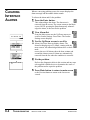
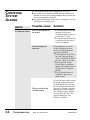
CONVEYING
SYSTEM
ALARMS
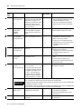
The No Material Alarm can be triggered in two ways:
l The Alarm Check signals an alarm after the operator-set
number of consecutive loading attempts fails to satisfy the
receiver’s demand for material.
l The optional fill sensor in the receiver or hopper is not satisfied after one loading cycle.
Alarm
Possible cause
No Material Alarm
There is no material at
the source.
Loader Settings are
incorrect.
There is a leak in the
vacuum system.
6-6
TROUBLESHOOTING
Basic 32 Loader Control
Solution
r Verify that there is enough
material at the source,
including regrind sources if
a ratio valve is used.
r Verify that the material line
is connected to the correct
source of material.
If the parameters set on the
Loader Settings screen are
incorrect, material demand
may not be satisfied.
r Verify that the Load Time,
or Load Time plus Purge
Time, is sufficient to fill the
receiver. Adjust as needed.
r Verify that the Alarm
Check allows a sufficient
number of loading cycles to
fill the receiver. Adjust as
needed.
r Verify that the loader is
assigned to the correct
pump system.
If there are leaks in the system,
the pump cannot pull a good
vacuum and the receiver may
have no or little material flowing into it. Check the vacuum
pump gauge. If the reading is
low, check all hoses, gaskets,
receiver lids, and valves for
signs of damage or wear.
Replace as needed.
UGC007/0702
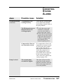
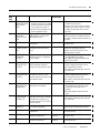
CONVEYING
SYSTEM
ALARMS
Alarm
Possible cause
Solution
No Material Alarm
(continued)
Vacuum pump is not
working correctly.
Verify that the vacuum pump
is on, connected to the B32
and working correctly. Refer to
the pump manual.
Pump Overload
UGC007/0702
The fill/demand sensor or
demand switch is not
working properly.
r Verify that sensors and
switches are connected
correctly at the loader or
hopper and at the control.
r Verify that fill and demand
sensors are set at the correct
height and adjusted properly. Refer to manuals supplied with the fill or
demand signaling device.
Compressed air lines are
not connected correctly.
If a compressed air line is not
connected to vacuum or material valves, the valves cannot
open to allow the pump to
draw material into the receiver.
Verify that compressed air
lines supplying the correct
pressure have been connected
to the vacuum sequencing
valve, ratio valve, pocket conveying or purge valve.
The vacuum pump
overload has tripped.
This alarm will prevent the
pump from being energized
until the overload is corrected.
Refer to the pump manual to
correct the problem.
Basic 32 Loader Control
TROUBLESHOOTING
6-7
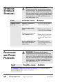
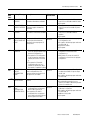
OPERATOR
INTERFACE
PROBLEMS
WARNING: Electrical shock hazard
Diagnosing electrical and processor problems
require access to the electrical enclosure while
power is on. Only qualified electrical technicians,
who are trained in how to avoid voltage hazards,
should perform troubleshooting procedures that
require access to the B32 Input/Output enclosure while power is on.
Solution
Fault
Possible cause
Terminal does not
power up.
Improper connection to
power source
r Verify wiring and connections to power source.
Incorrect input voltage
level.
r Verify correct voltage is
present at power terminals.
DC power wires reversed
(DC terminals only).
Power terminal block not
fully seated (PV300 terminals only).
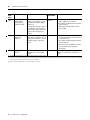
PROCESSOR
AND POWER
PROBLEMS
Fault
r Make sure DC power positive and negative are connected to the proper terminals.
r Verify power terminal
block is snapped onto base
of PV300 Micro.
WARNING: Electrical shock hazard
Diagnosing electrical and processor problems
require access to the electrical enclosure while
power is on. Only qualified electrical technicians,
who are trained in how to avoid voltage hazards,
should perform troubleshooting procedures that
require access to the B32 Input/Output enclosure while power is on.
Possible cause
Solution
See APPENDIX C “TROUBLESHOOTING YOUR SYSTEM” for a complete listing of
process and power faults, causes and solutions.
6-8
TROUBLESHOOTING
Basic 32 Loader Control
UGC007/0702
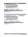
WARNING: Electrical shock hazard
Diagnosing electrical and processor problems
require access to the electrical enclosure while
power is on. Only qualified electrical technicians,
who are trained in how to avoid voltage hazards,
should perform troubleshooting procedures that
require access to the B32 Input/Output
enclosure while power is on.
Error/Alarm
Possible cause
See APPENDIX D: “FAULT MESSAGES
CPU faults, causes and solutions.
AND
Solution
ERROR CODES” for a complete listing of
WARNING: Electrical shock hazard
Diagnosing electrical and processor problems
require access to the electrical enclosure while
power is on. Only qualified electrical technicians,
who are trained in how to avoid voltage hazards,
should perform troubleshooting procedures that
require access to the B32 Input/Output enclosure while power is on.
Error
CPU FAULTS
Possible cause
I/O ERRORS
Solution
See APPENDIX D: “FAULT MESSAGES AND ERROR CODES” for a complete listing of
input/output errors, causes and solutions.
UGC007/0702
Basic 32 Loader Control
TROUBLESHOOTING
6-9
Conair has made the largest investment in customer support in
the plastics industry. Our service experts are available to help
with any problem you might have installing and operating
your equipment. Your Conair sales representative also can
help analyze the nature of your problem, assuring that it did
not result from misapplication or improper use.
WE’RE HERE
TO HELP
To contact Customer Service personnel, call:
HOW TO CONTACT
CUSTOMER
SERVICE
From outside the United States, call: 814-437-6861
You can commission Conair service personnel to provide onsite service by contacting the Customer Service Department.
Standard rates include an on-site hourly rate, with a one-day
minimum plus expenses.
If you do have a problem, please complete the
following checklist before calling Conair:
r Make sure you have all model, serial and parts list
numbers for your particular equipment. Service
personnel will need this information to assist you.
BEFORE YOU
CALL ...
r Make sure power is supplied to the equipment.
r Make sure that all connectors and wires within
and between control systems and related
components have been installed correctly.
r Check the troubleshooting guide of this manual
for a solution.
r Thoroughly examine the instruction manual(s)
for associated equipment, especially controls.
Each manual may have its own troubleshooting
guide to help you.
r Check that the equipment has been operated as
described in this manual.
r Check accompanying schematic drawings for
information on special considerations.
UGC007/0702
SERVICE INFORMATION
Additional manuals and
prints for your Conair
equipment may be
ordered through the
Customer Service or
Parts Departments for a
nominal fee.
APPENDIX A1
EQUIPMENT
GUARANTEE
Conair guarantees the machinery and equipment on this order,
for a period as defined in the quotation from date of shipment,
against defects in material and workmanship under the normal
use and service for which it was recommended (except for
parts that are typically replaced after normal usage, such as filters, liner plates, etc.). Conair’s guarantee is limited to replacing, at our option, the part or parts determined by us to be
defective after examination. The customer assumes the cost of
transportation of the part or parts to and from the factory.
PERFORMANCE
WARRANTY
Conair warrants that this equipment will perform at or above
the ratings stated in specific quotations covering the equipment or as detailed in engineering specifications, provided the
equipment is applied, installed, operated and maintained in the
recommended manner as outlined in our quotation or specifications.
Should performance not meet warranted levels, Conair at its
discretion will exercise one of the following options:
l Inspect the equipment and perform alterations or adjustments to satisfy performance claims. (Charges for such
inspections and corrections will be waived unless failure
to meet warranty is due to misapplication, improper
installation, poor maintenance practices or improper operation.)
l Replace the original equipment with other Conair equipment that will meet original performance claims at no
extra cost to the customer.
l Refund the invoiced cost to the customer. Credit is subject
to prior notice by the customer at which time a Return
Goods Authorization Number (RGA) will be issued by
Conair’s Service Department. Returned equipment must
be well crated and in proper operating condition, including all parts. Returns must be prepaid.
Purchaser must notify Conair in writing of any claim and provide a customer receipt and other evidence that a claim is
being made.
WARRANTY
LIMITATIONS
Except for the Equipment Guarantee and Performance
Warranty stated above, Conair disclaims all other warranties
with respect to the equipment, express or implied, arising by
operation of law, course of dealing, usage of trade or otherwise, including but not limited to the implied warranties of
merchantability and fitness for a particular purpose.
A2
WARRANTY INFORMATION
APPENDIX
IMS0003/0796
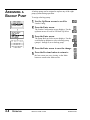
The program can be restored to the plant configuration if for
some reason the program has been interrupted.
To restore the program:
RESTORING THE
PROGRAM
1 Use the Up/Down arrows to scroll to
Loader Config.
2 Press the Enter arrow.
The Loader Configuration screen displays. Use the
up/down arrows to scroll to Save Config
3 Press the Enter arrow.
The Save Configuration screen displays. Use the
scroll up/down buttons to select Program Mode.
4
5
Press the Enter arrow to save the change.
Press the Previous button to return to
the last screen you were viewing, or the Main
button to return to the Main screen.
UGC007/0702
RESTORING THE PROGRAM
APPENDIX B1
Appendix
C
Troubleshooting Your System
This chapter describes how to troubleshoot your controller. Topics include:
• understanding the controller LED status
• controller error recovery model
• identifying controller faults
• calling Rockwell Automation for assistance
Understanding
Controller LEDs
The controller status LEDs provide a mechanism to determine the current status of
the controller if a programming device is not present or available.
LED
Color
Indicates
POWER
off
no input power
green
power on
off
controller is not in Run mode or REM Run
green
controller is in Run mode or REM Run
green
flashing
system is not in Run mode; memory module transfer is in
progress
off
no fault detected
D.C. INPUTS
RUN
24V SINK / SOURCE
POWER
DC/RELAY OUT
RUN
FAULT
FORCE
BAT. LO
COMM 0
DCOMM
24V SOURCE
FAULT
red flashing faulted user program
red
processor hardware fault or critical fault
off
no forces installed
amber
forces installed
BATTERY LOW
off
battery OK
red
battery needs replacement (See page B-2.)
COMM 0
off
flashes when communications are active
FORCE
green
COMM 1
(1764-LRP only)
off
flashes when communications are active
DCOMM(1)
off
user configured communications mode is active
green
default communications mode active
INPUTS
off
input is not energized
amber
input is energized (logic status)
OUTPUTS
off
output is not energized
amber
output is energized (logic status)
green
(1) When using a 1764-LRP processor, the DCOMM LED applies only to Channel 0.
Basic 32 Loader Control UGC007/0702
C-2
Troubleshooting Your System
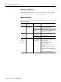
When Operating Normally
The POWER and RUN LEDs are on. If a force condition is active, the FORCE
LED turns on and remains on until all forces are removed.
When an Error Exists
If an error exists within the controller, the controller LEDs operate as described in
the following tables.
If the LEDS The Following
indicate:
Error Exists
Probable Cause
All LEDS off No input power or No Line Power
power supply error
Power and Hardware faulted
FAULT LEDs
on solid
Power LED
on and
FAULT LED
flashing
Application fault
Recommended Action
Verify proper line voltage and
connections to the controller.
Power Supply
Overloaded
This problem can occur intermittently if
power supply is overloaded when output
loading and temperature varies.
Processor
Hardware Error
Cycle power. Contact your local
Conair Service representative if
the error persists.
Loose Wiring
Verify connections to the controller.
Hardware/
Software Major
Fault Detected
4. Monitor Status File Word S:6 for
major error code. See page C-4 for
more information.
5. Remove hardware/software
condition causing fault.
6. Clear Major Error Halted flag, bit
S2:1/13.
7. Attempt a controller Run mode entry.
If unsuccessful, repeat recommended
action steps above or contact your
Coniar Service representative.
Basic 32 Loader Control
UGC007/0702
Troubleshooting Your System
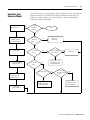
Controller Error
Recovery Model
Identify the error code
and description.
C-3
Use the following error recovery model to help you diagnose software and hardware
problems in the micro controller. The model provides common questions you
might ask to help troubleshoot your system. Refer to the recommended pages
within the model for further help.
No
Is the error
hardware
related?
Start
Yes
Refer to page C-2 for
probable cause and
recommended action.
Are the wire
connections
tight?
Tighten wire
connections.
No
Yes
Clear fault.
Is the Power
LED on?
No
Is the RUN
LED on?
Check power.
Yes
Yes
Correct the condition
causing the fault.
No
Is power supplied
to the controller?
Refer to page C-2 for
probable cause and
recommended action.
No
Yes
Is the Fault LED on?
Return controller to
RUN or any of the
REM test modes.
Yes
See page C-2 for
probable cause and
recommended action.
No
Is an input LED
accurately showing
status?
No
Yes
See page C-2 for
probable cause and
recommended action.
Test and verify
system operation.
Basic 32 Loader Control UGC007/0702
C-4
Troubleshooting Your System
Identifying Controller
Faults
While a program is executing, a fault may occur within the operating system or
your program. When a fault occurs, you have various options to determine what
the fault is and how to correct it. This section describes how to clear faults and
provides a list of possible advisory messages with recommended corrective actions.
Automatically Clearing Faults
You can automatically clear a fault by cycling power to the controller when the
Fault Override at Power-up bit (S:1/8) is set in the status file.
You can also configure the controller to clear faults and go to RUN every time the
controller is power cycled. This is a feature that OEMs can build into their
equipment to allow end users to reset the controller. If the controller faults, it can
be reset by simply cycling power to the machine. To accomplish this, set the
following bits in the status file:
• S2:1/8 - Fault Override at Power-up
• S2:1/12 - Mode Behavior
If the fault condition still exists after cycling power, the controller re-enters the fault
mode. For more information on status bits, refer to the MicroLogix 1200 and
MicroLogix 1500 Instruction Set Reference Manual.
NOTE
You can declare your own application-specific major fault by
writing your own unique value to S:6 and then setting bit S:1/13
to prevent reusing system defined codes. The recommended
values for user defined faults are FF00 to FF0F.
Manually Clearing Faults Using the Fault Routine
The occurrence of recoverable or non-recoverable user faults can cause the user
fault subroutine to be executed. If the fault is recoverable, the subroutine can be
used to correct the problem and clear the fault bit S:1/13. The controller then
continues in the Run or test mode.
The subroutine does not execute for non-user faults. Refer to the MicroLogix 1200
and MicroLogix 1500 Instruction Set Reference Manual for information on creating a
user fault subroutine.
Fault Messages
Refer to the MicroLogix 1200 and 1500 Instruction Set Reference Manual for the
controller fault messages that can occur during operation of the MicroLogix 1500
programmable controllers. Each fault message includes the error code description,
the probable cause, and the recommended corrective action.
Basic 32 Loader Control
UGC007/0702
Appendix
D
Fault Messages and Error Codes
This chapter describes how to troubleshoot your controller. Topics
include:
• identifying controller faults
• contacting Rockwell Automation for assistance
Identifying Controller
Faults
While a program is executing, a fault may occur within the operating
system or your program. When a fault occurs, you have various options to
determine what the fault is and how to correct it. This section describes
how to clear faults and provides a list of possible advisory messages with
recommended corrective actions.
Automatically Clearing Faults
You can automatically clear a fault by cycling power to the controller
when the Fault Override at Power-Up bit (S:1/8) is set in the status file.
You can also configure the controller to clear faults and go to RUN every
time the controller is power cycled. This is a feature that OEMs can build
into their equipment to allow end users to reset the controller. If the
controller faults, it can be reset by simply cycling power to the machine.
To accomplish this, set the following bits in the status file:
• S2:1/8 - Fault Override at Power-up
• S2:1/12 - Mode Behavior
If the fault condition still exists after cycling power, the controller
re-enters the fault mode. For more information on status bits, see System
Status File on page C-1.
NOTE
Basic 32LoaderControl
You can declare your own application-specific major fault
by writing your own unique value to S:6 and then setting
bit S:1/13 to prevent reusing system defined codes. The
recommended values for user-defined faults are FF00 to
FF0F.
UGC007/0702
D-2
Fault Messages and Error Codes
Manually Clearing Faults Using the Fault Routine
The occurrence of recoverable or non-recoverable user faults can cause
the user fault subroutine to be executed. If the fault is recoverable, the
subroutine can be used to correct the problem and clear the fault bit S:1/
13. The controller then continues in the Run or test mode.
The subroutine does not execute for non-user faults. See User Fault
Routine on page 18-6 for information on creating a user fault subroutine.
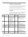
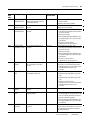
Fault Messages
This section contains fault messages that can occur during operation of
the MicroLogix 1200 and MicroLogix 1500 programmable controllers. Each
table lists the error code description, the probable cause, and the
recommended corrective action.
Error
Code
(Hex)
0001
0002
0003
0004
Advisory Message
Description
NVRAM ERROR
Fault
Classification
The default program is loaded to the Non-User
controller memory. This occurs:
• if a power down occurred during
program download or transfer
from the memory module.
• RAM integrity test failed.
• FLASH integrity test failed
(MicroLogix 1200 only).
UNEXPECTED RESET • The controller was unexpectedly Non-User
reset due to a noisy environment
or internal hardware failure.
• The default program is loaded.
(MicroLogix 1500 only)
• Retentive Data is lost. See page
C-12. (MicroLogix 1200 only)
Memory module memory error. This Non-User
MEMORY MODULE
error can also occur when going to
USER PROGRAM IS
the Run mode.
CORRUPT
MEMORY INTEGRITY While the controller was powered Non-User
ERROR
up, ROM or RAM became corrupt.
UGC007/0702
Basic 32 Loader Control
Recommended Action
• Re-download or transfer the program.
• Verify battery is connected (MicroLogix
1500 only).
• Contact your Conair Service
representative if the error persists.
• Refer to proper grounding guidelines and
using surge suppressors in your controller’s
User Manual.
• Verify battery is connected (MicroLogix
1500 only).
• Contact your Conair service
representative if the error persists.
Re-program the memory module. If the error
persists, replace the memory module.
• Cycle power on your unit. Then,
re-download your program and start up
your system.
• Refer to proper grounding guidelines and
using surge suppressors in your controller’s
User Manual.
• Contact your Coniar Service
representative if the error persists.
Fault Messages and Error Codes
D-3
Error
Code
(Hex)
0006
Advisory Message
Description
Fault
Classification
Recommended Action
MEMORY MODULE
HARDWARE FAULT
The memory module hardware
faulted or the memory module is
incompatible with OS.
Non-User
• Upgrade the OS to be compatible with
memory module.
• Obtain a new memory module.
0007
MEMORY MODULE
TRANSFER ERROR
FATAL INTERNAL
SOFTWARE ERROR
Failure during memory module
transfer.
An unexpected software error
occurred.
Non-User
0009
FATAL INTERNAL
HARDWARE ERROR
An unexpected hardware error
occurred.
Non-User
Re-attempt the transfer. If the error persists,
replace the memory module.
• Cycle power on your unit. Then,
re-download your program and re-initialize
any necessary data.
• Start up your system.
• Refer to proper grounding guidelines and
using surge suppressors in your controller’s
User Manual.
• Contact your Conair Service
representative if the error persists.
• Cycle power on your unit. Then,
re-download your program and re-initialize
any necessary data.
• Start up your system.
• Refer to proper grounding guidelines and
using surge suppressors in your controller’s
User Manual.
• Contact your Conair Service
representative if the error persists.
000A
OS MISSING OR
CORRUPT
The operating system required for
the user program is corrupt or
missing.
Non-User
• Download a new OS using ControlFlash.
• Contact your local Rockwell Automation
representative for more information about
available operating systems your
controller.
000B
BASE HARDWARE
FAULT
The base hardware faulted or is
incompatible with the OS.
Non-User
• Upgrade the OS using ControlFlash.
• Replace the Controller (MicroLogix 1200
only).
• Replace the Base Unit (MicroLogix 1500
only).
• Contact your Conair Service
representative for more information about
available operating systems your
controller.
0011
EXECUTABLE FILE 2 IS
MISSING
LADDER PROGRAM
ERROR
Ladder File 2 is missing from the
program.
The ladder program has a memory
integrity problem.
Non-User
• Re-compile and reload the program.
Non-User
• Reload the program or re-compile and
reload the program. If the error persists, be
sure to use RSI programming software to
develop and load the program.
• Refer to proper grounding guidelines and
using surge suppressors in your controller’s
User Manual.
I/O CONFIGURATION
FILE ERROR
The user program I/O configuration
is invalid.
Non-User
Re-compile and reload the program, and enter
the Run mode. If the error persists, be sure to
use RSI programming software to develop
and load the program.
0008
0012
0015
Non-User
Basic 32 Loader Control
UGC007/0702
D-4
Error
Code
(Hex)
0016
0017
0018
001A
0020
0021
0022
0023
Fault Messages and Error Codes
Advisory Message
Description
Fault
Classification
Recommended Action
• Either reset bit S:1/9 if this is consistent
The user fault routine was executed Recoverable
at power-up, prior to the main ladder
with the application requirements, and
program. Bit S:1/13 (Major Error
change the mode back to RUN, or
Halted) was not cleared at the end of
• clear S:1/13, the Major Error Halted bit,
the User Fault Routine. The User
before the end of the User Fault Routine.
Fault Routine ran because bit S:1/9
was set at power-up.
Bit S:2/9 is set in the controller and Non-Recoverable Transfer the memory module program to the
NVRAM/MEMORY
controller and then change to Run mode.
the memory module user program
MODULE USER
does not match the controller user
PROGRAM
program.
MISMATCH
The user program in the memory
Non-User
MEMORY MODULE
• Upgrade the OS using ControlFlash to be
module is incompatible with the OS.
USER PROGRAM
compatible with the memory module.
INCOMPATIBLE WITH
• Obtain a new memory module.
OS
• Contact your local Rockwell Automation
representative for more information about
available operating systems your
controller.
The user program is incompatible
Non-User
USER PROGRAM
• Upgrade the OS using ControlFlash.
INCOMPATIBLE WITH with the OS.
• Contact your Conair Service
OS AT POWER-UP
representative for more information about
available operating systems your
controller.
A minor fault bit (bits 0-7) in S:5 was Recoverable
MINOR ERROR AT
• Correct the instruction logic causing the
set at the end of scan.
END-OF-SCAN
error.
DETECTED
• Enter the status file display in your
programming software and clear the fault.
• Enter the Run mode.
Non-User
Re-apply power to the expansion I/O bank.
EXPANSION POWER A power failure is present on the
See Important note below.
expansion I/O bank.
FAIL (EPF)
(MicroLogix 1500 only) This error code is present only when
the controller is powered, and power
is not applied to the expansion I/O
bank. This is a self-clearing error
code. When power is re-applied to
the expansion I/O bank, the fault is
cleared. See Important note below.
If this fault occurs while the system is in the RUN mode, the controller faults. When expansion I/O
power is restored, the controller clears the fault and re-enters the RUN mode.
If you change the mode switch while this fault is present, the controller may not re-enter the RUN mode
IMPORTANT when expansion I/O power is restored.
If an EPF condition is present and expansion I/O power is OK, toggle the mode switch to PROGRAM and
then to RUN. The fault should clear and the controller enters the RUN mode.
WATCHDOG TIMER
The program scan time exceeded the Non-Recoverable • Determine if the program is caught in a
EXPIRED, SEE S:3
watchdog timeout value (S:3H).
loop and correct the problem.
• Increase the watchdog timeout value in
the status file.
STI ERROR
An error occurred in the STI
Recoverable
See the Error Code in the STI Function File for
configuration.
the specific error.
STARTUP
PROTECTION FAULT
Basic 32 Loader Control UGC007/0702
Fault Messages and Error Codes
Advisory Message
Description
INVALID OR
NONEXISTENT USER
FAULT ROUTINE
VALUE
Non-User
• A fault routine number was
entered in the status file, number
(S:29), but either the fault routine
was not physically created, or
• the fault routine number was less
than 3 or greater than 255.
• Either clear the fault routine file number
(S:29) in the status file, or
• create a fault routine for the file number
reference in the status file (S:29). The file
number must be greater than 2 and less
than 256.
0029
INSTRUCTION
INDIRECTION
OUTSIDE OF DATA
SPACE
An indirect address reference in the Recoverable
ladder program is outside of the
entire data file space.
002E
EII ERROR
Recoverable
0030
SUBROUTINE
NESTING EXCEEDS
LIMIT
An error occurred in the EII
configuration.
The JSR instruction nesting level
exceeded the controller memory
space.
0031
UNSUPPORTED
INSTRUCTION
DETECTED
The program contains an
instruction(s) that is not supported
by the controller.
Non-User
0032
SQO/SQC/SQL
OUTSIDE OF DATA
FILE SPACE
Recoverable
A sequencer instruction length/
position parameter references
outside of the entire data file space.
Correct the program to ensure that there are
no indirect references outside data file space.
Re-compile, reload the program and enter the
Run mode.
See the Error Code in the EII Function File for
the specific error.
Correct the user program to reduce the
nesting levels used and to meet the
restrictions for the JSR instruction. Then
reload the program and Run.
• Modify the program so that all instructions
are supported by the controller.
• Re-compile and reload the program and
enter the Run mode.
• Correct the program to ensure that the
length and position parameters do not
point outside data file space.
• Re-compile, reload the program and enter
the Run mode.
0033
BSL/BSR/FFL/FFU/LFL/ The length/position parameter of a Recoverable
LFU CROSSED DATA BSL, BSR, FFL, FFU, LFL, or LFU
instruction references outside of the
FILE SPACE
entire data file space.
0034
NEGATIVE VALUE IN
TIMER PRESET OR
ACCUMULATOR
A negative value was loaded to a
timer preset or accumulator.
0035
ILLEGAL
INSTRUCTION IN
INTERRUPT FILE
The program contains a Temporary Non-Recoverable
End (TND), Refresh (REF), or Service
Communication instruction in an
interrupt subroutine (STI, EII, HSC) or
user fault routine.
• Correct the program.
• Re-compile, reload the program and enter
the Run mode.
0036
0037
INVALID PID
PARAMETER
HSC ERROR
003B
PTO ERROR
003C
PWM ERROR
An invalid value is being used for a
PID instruction parameter.
An error occurred in the HSC
configuration.
An error occurred in the PTO
instruction configuration.
An error occurred in the PWM
instruction configuration.
Process Control Instruction for
more information about the PID instruction.
See the Error Code in the HSC Function File
for the specific error.
See the Error Code in the PTO Function File for
the specific error.
See the Error Code in the PWM Function File
for the specific error.
Error
Code
(Hex)
0028
Fault
Classification
D-5
Non-User
Recoverable
Recoverable
Recoverable
Recoverable or
Non-User
Recoverable or
Non-User
Recommended Action
• Correct the program to ensure that the
length and position parameters do not
point outside of the data space.
• Re-compile, reload the program and enter
the Run mode.
• If the program is moving values to the
accumulated or preset word of a timer,
make certain these values are not
negative.
• Reload the program and enter the Run
mode.
Basic 32 Loader Control
UGC007/0702
D-6
Error
Code
(Hex)
003D
003E
003F
Fault Messages and Error Codes
Advisory Message
Description
Fault
Classification
INVALID SEQUENCER A sequencer instruction (SQO, SQC, Recoverable
LENGTH/POSITION
SQL) length/position parameter is
greater than 255.
Recoverable
INVALID BIT SHIFT OR A BSR or BSL instruction length
parameter is greater than 2048 or an
LIFO/FIFO
FFU, FFL, LFU, LFL instruction length
PARAMETER
parameter is greater than 128 (word
file) or greater than 64 (double word
file)
Recoverable
COP/FLL OUTSIDE OF A COP or FLL instruction length
DATA FILE SPACE
parameter references outside of the
entire data space.
Recommended Action
Correct the user program, then re-compile,
reload the program and enter the Run mode.
Correct the user program or allocate more
data file space using the memory map, then
reload and Run.
• Correct the program to ensure that the
length and parameter do not point outside
of the data file space.
• Re-compile, reload the program and enter
the Run mode.
0050
CONTROLLER TYPE
MISMATCH
Non-User
A particular controller type was
selected in the user program
configuration, but did not match the
actual controller type.
• Connect to the hardware that is specified
in the user program, or
• Reconfigure the program to match the
attached hardware.
0051
BASE TYPE
MISMATCH
A particular hardware type (AWA, Non-User
BWA, BXB) was selected in the user
program configuration, but did no
match the actual base.
• Connect to the hardware that is specified
in the user program, or
• Reconfigure the program to match the
attached hardware.
0052
MINIMUM SERIES
ERROR
The hardware minimum series
selected in the user program
configuration was greater than the
series on the actual hardware.
Non-User
• Connect to the hardware that is specified
in the user program, or
• Reconfigure the program to match the
attached hardware.
0070
The required expansion I/O
EXPANSION I/O
terminator was removed.
TERMINATOR
REMOVED
(MicroLogix 1500 only)
Non-Recoverable
• Check the expansion I/O terminator on the
last
I/O module.
• Cycle power.
xx71(1)
EXPANSION I/O
HARDWARE ERROR
The controller cannot communicate Non-Recoverable
with an expansion I/O module.
• Check connections.
• Check for a noise problem and be sure
proper grounding practices are used.
• Replace the module.
• Cycle power.
xx79(1)
EXPANSION I/O
MODULE ERROR
An expansion I/O module generated Non-Recoverable
an error.
• Refer to the I/O Module Status (IOS) file.
• Consult the documentation for your
specific I/O module to determine possible
causes of a module error.
0080
EXPANSION I/O
TERMINATOR
REMOVED
(MicroLogix 1500 only)
EXPANSION I/O
HARDWARE ERROR
The required expansion I/O
terminator was removed.
• Check expansion I/O terminator on last I/O
module.
• Cycle power.
xx81(1)
Non-User
The controller cannot communicate Non-User
with an expansion I/O module.
Basic 32 Loader Control UGC007/0702
• Check connections.
• Check for a noise problem and be sure
proper grounding practices are used.
• Replace the module.
• Cycle power.
Fault Messages and Error Codes
Advisory Message
Description
MAX I/O CABLES
EXCEEDED
The maximum number of expansion Non-User
I/O cables allowed was exceeded.
• Reconfigure the expansion I/O system so
that it has an allowable number of cables.
• Cycle power.
0084
MAX I/O POWER
SUPPLIES EXCEEDED
• Reconfigure the expansion I/O system so
that it has the correct number of power
supplies.
0085
MAX I/O MODULES
EXCEEDED
The maximum number of expansion Non-User
I/O power supplies allowed was
exceeded.
The maximum number of expansion Non-User
I/O modules allowed was exceeded.
xx86(1)
An expansion I/O module could not
EXPANSION I/O
MODULE BAUD RATE communicate at the baud rate
specified in the user program I/O
ERROR
configuration.
xx87(1)
I/O CONFIGURATION
MISMATCH
• The expansion I/O configuration Non-User
in the user program did not match
the actual configuration, or
• The expansion I/O configuration
in the user program specified a
module, but one was not found,
or
• The expansion I/O module
configuration data size for a
module was greater than what
the module is capable of holding.
• Either correct the user program I/O
configuration to match the actual
configuration, or
• With power off, correct the actual I/O
configuration to match the user program
configuration.
xx88(1)
EXPANSION I/O
MODULE
CONFIGURATION
ERROR
The number of input or output image Non-User
words configured in the user
program exceeds the image size in
the expansion I/O module.
• Correct the user program I/O configuration
to reduce the number of input or output
words, and
• Re-compile, reload the program and enter
the Run mode.
xx89(1)(2) EXPANSION I/O
MODULE ERROR
An expansion I/O module generated Non-User
an error.
• Refer to the I/O status file.
• Consult the documentation for your
specific I/O module to determine possible
causes of a module error.
xx8A(1)(2) EXPANSION I/O
CABLE
CONFIGURATION
MISMATCH ERROR
• Either an expansion I/O cable is Non-User
configured in the user program,
but no cable is present, or
• an expansion I/O cable is
configured in the user program
and a cable is physically present,
but the types do not match.
• Correct the user program to eliminate a
cable that is not present
• Re-compile, reload the program and enter
the Run mode, or
• Add the missing cable.
• Cycle power.
Error
Code
(Hex)
0083
Fault
Classification
D-7
Non-User
Recommended Action
• Reconfigure the expansion I/O system so
that it has an allowable number of
modules.
• Cycle power.
• Change the baud rate in the user program
I/O configuration, and
• Re-compile, reload the program and enter
the Run mode, or
• Replace the module.
• Cycle power.
Basic 32 Loader Control
UGC007/0702
D-8
Fault Messages and Error Codes
Error
Code
(Hex)
Advisory Message
Description
Fault
Classification
Recommended Action
xx8B(1)(2) EXPANSION I/O
POWER SUPPLY
CONFIGURATION
MISMATCH ERROR
• Either an expansion I/O power
Non-User
supply is configured in the user
program, but no power supply is
present, or
• an expansion I/O power supply is
configured in the user program
and a power supply is physically
present, but the types do not
match.
• Correct the user program to eliminate a
power supply that is not present
• Re-compile, reload the program and enter
the Run mode, or
• With power removed, add the missing
power supply.
xx8C(1)(2) EXPANSION I/O
OBJECT TYPE
MISMATCH
An expansion I/O object (i.e. cable, Non-User
power supply, or module) in the user
program I/O configuration is not the
same object type as is physically
present.
• Correct the user program I/O configuration
so that the object types match the actual
configuration, and
• Re-compile, reload the program and enter
the Run mode. Or
• Correct the actual configuration to match
the user program I/O configuration.
• Cycle power.
0x1F39
The first word of string data contains Recoverable
a negative, zero, or value greater
than 82.
Check the first word of the string data
element for invalid values and correct the
data.
(1)
INVALID STRING
LENGTH(3)
xx indicates module number. If xx = 0, problem cannot be traced to a specific module.
(2) The xx in this error code means that the error occurs at the location of the last properly configured Expansion I/O module +1. You should use this information in conjunction
with the specific error code to determine the source of the problem.
(3) Applies to MicroLogix 1500 1764-LSP Series B and 1764-LRP Processors.
Basic 32 Loader Control UGC007/0702