1
Trilogy Networx™ System
345 Bayview Avenue
Amityville, New York 11701
For Sales and Repairs 1-800-ALA-LOCK
For Technical Service 1-800-645-9440
Publicly traded on NASDAQ
Symbol: NSSC
NETWORXPANEL
Wireless Networx Control Panel
INSTALLATION INSTRUCTIONS
© ALARM LOCK 2010
WI1856 11/10
))
))
)
))
W
))
))
))
))
))
))
)
- 45
(RJ
1
2.1
ired
or W
)
Wir
or W
HI D
HID CORPORATION
NETPDK
GATEWAY
NETDK
Wire up to
2 Wiegand
Devices
irele
ed
irele
8
ss
0
Existing
Corporate
Ethernet
Network
(RJ
- 45
)
ss 8
02.1
1
Router
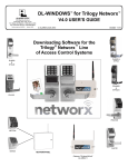
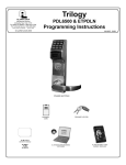
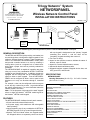
NETWORXPANEL
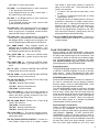
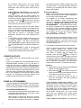
NETDK and/or NETPDK keypads (and/or Wiegand devices) wired to a dedicated NETWORXPANEL control panel
GENERAL DESCRIPTION
The NETDK and NETPDK (with proximity card reader) are
secured single-door or double-door digital keypads for use
within the wireless Networx™ system. These keypads are
wired to the dedicated NETWORXPANEL control panel
and provide controlled access to a door by releasing a
locking device (such as a magnetic lock or electric door
strike) when a proper user code or proximity credential is
presented.
The NETWORXPANEL is capable of controlling two doors
using up to two of any combination NETDK or NETPDK
keypads or two Wiegand devices. In addition, the panel is
equipped with two relays that can be independently assigned to either or both keypads. Thus the NETWORXPANEL can be configured to allow a user to pass in both
directions--or in only one direction--through a controlled
door.
For example, a door can be configured to allow everyone
to exit, but only a select few to enter. Log entries indicate
the specific keypad used. For more information about the
Networx system, see OI352.
Note: For the purposes of this manual, the word "keypad"
refers to either the Networx™ NETPDK model keypad or
the Networx™ NETDK model keypad.
FEATURES
The NETWORXPANEL dedicated control panel contains:
● Circuit board with onboard flash memory;
● 12V power supply, with transformer and rechargeable
back-up battery;
● Inputs supporting two of any combination of NETDK or
NETPDK keypads, PLUS up to two Wiegand devices;
● Special "Two Door Mode" allows two keypads and/or
two Wiegand devices to separately control two doors,
with one keypad is designated as the "primary" keypad
controlling door number 1, and the other as the
"secondary" keypad controlling door number 2;
● Two Form-C relays;
● Inputs for door position contact to indicate the status of
the door, open or closed;
● Inputs for a remote release button or sensor;
● Onboard bi-directional Networx radio;
● Wiegand interface supports Wiegand device data, red
LED, green LED, and sounder.
SPECIFICATIONS
NETWORXPANEL
Housing Dimensions (H x W x D): 10.5 x 8.5 x 3 inches
(26.6 x 21.6 x 7.6 cm)
TABLE OF CONTENTS
GENERAL DESCRIPTION ....................................................................1
FEATURES ...........................................................................................1
SPECIFICATIONS ................................................................................1
WIEGAND DATA FORMATS SUPPORTED .........................................2
LED AND BUTTON DESCRIPTIONS ...................................................2
TERMINAL DESCRIPTIONS ................................................................2
PLAN YOUR INSTALLATION ...............................................................3
TYPICAL INSTALLATIONS...................................................................4
INSTALLATION STEPS ........................................................................5
WIRING TWO KEYPADS TO THE NETWORXPANEL ........................6
"TWO DOOR MODE" ............................................................................6
FIRST TIME POWER UP ......................................................................7
POWER RE-APPLIED...........................................................................8
ERASE ALL PROGRAMMING ..............................................................8
ENROLLING WIEGAND SWIPE CARDS .............................................9
BASIC WIRING EXAMPLES ............................................................... 10
WIRING DIAGRAM ............................................................................. 12
WARRANTY ........................................................................................ 12
1
Operating Temperature: 14-120°F (–10-49°C)
Input Power: 16.5VAC via Class 2 Plug-In 50VA
Transformer (supplied model TRF-14)
Maximum Lock Power Output Current: 1.5A @
12VDC
Maximum Wiegand Power Output Current: 250mA
@ 12VDC
Maximum Wiegand Red and Green LED Current:
20mA each output
Maximum Sounder Current: 100mA
Maximum Keypad Power Output Current: 200mA
@ 12VDC
Primary and Secondary Relays: SPDT Form C, N/
O, N/C 8A @ 30VAC or VDC
Supplied Backup Battery: Sealed Lead Acid 4AH
Battery Backup Time: Approximately 2 hours at full
load
NETDK / NETPDK Networx Keypads
Power Requirements: 12VDC supplied by NETWORXPANEL
Idle Current: 10mA
Maximum Wire Length: 200 feet (61m)
Recommended Wire Size: 24 AWG minimum
Proximity Card Formats Supported: Alarm Lock
standard 36 bit format or HID standard 26 bit format
(for use with the model NETPDK only)
WIEGAND DATA FORMATS SUPPORTED
The NETWORXPANEL Wiegand inputs (terminals T4T8) are compatible with all Wiegand devices that output their data in a "data1 / data0" format. If you are unsure of the compatibility of your Wiegand device data
format, call Alarm Lock customer service (have your
DL-Windows software version number available when
calling).
Wiegand Devices Supported
The NETWORXPANEL control panel has been tested
to work with the following Wiegand device models:
• HID Classic Swipe Wiegand Reader Model 310
(Continental 36-bit card format compatible).
• HID ProxPro with Keypad Model 5355
• HES model RF5910 Hybrid Electric Strike with
HID125k reader
Note that other Wiegand device models not tested may
also be fully compatible. For more information, see the
section "ENROLLING WIEGAND SWIPE CARDS" further in this manual.
LED AND BUTTON DESCRIPTIONS
The NETWORXPANEL PC board contains two LED's
and 1 button, as follows:
(LD1) Activity LED: Green LED located on the right
2
side of the PC board; flickers during keypad data
transfer.
(LD2) AC Power LED: Located on the left side of the
PC board, this LED lights when the panel is powered
(AC is present).
(S2) Reset Button: Located on the right side of the PC
board; press and hold for 15 seconds to clear the
NETWORXPANEL memory. Note: When memory is
cleared, the green LD1 LED will flash once every second for 5 seconds. In addition, all keypad and device
LED's will flash once every second in unison. The
keypad sounders and device sounders (if so
equipped) will also sound in unison with the LED
flashes.
Note: Although the Reset button will clear all NETWORXPANEL memory, if two NETPDK or NETDK
keypads are wired to the NETWORXPANEL, the primary and secondary keypad designations will NOT
be cleared; this keypad identification data is stored
within the memory located inside the keypad itself.
See the section "Designate Primary and Secondary
Keypads" for the operation of this feature.
TERMINAL DESCRIPTIONS
From left to right, the PC board terminals are as follows:
(T1) EGND: Wire earth ground using a No. 16 AWG. or
larger wire to a metal cold-water pipe. Do not use a
gas pipe, plastic pipe or AC ground connections.
NOTE: Grounding connections should avoid bends in
the grounding wire whenever possible.
(T2-T3) AC IN: Connect to the supply 16.5VAC transformer. Use 16AWG wire for shorter runs, and use
14AWG for longer runs. 25 feet maximum.
(T4-T8) WIEGAND INPUTS
Two Wiegand devices are supported on the input terminals as detailed below.
(T4) WOA: If one Wiegand device is used, do not connect any wires to this terminal; use the WO terminal
below.
If two Wiegand devices are used, connect the "Data
0" wire from the second Wiegand device to this terminal, (connect the "Data 0" wire from the first Wiegand
device to the WO terminal).
(T5) WO: If one Wiegand device is used, connect the
"Data 0" wire to this terminal.
If two Wiegand devices are used, connect the "Data
0" wire from the first Wiegand device to this terminal
(connect the "Data 0" wire from the second Wiegand
device to the WOA terminal).
(T6) W1: If one Wiegand device is used, connect the
"Data 1" wire to this terminal.
If two Wiegand devices are used, connect both Wie-
gand "Data 1" wires to this terminal.
(T7) PWR: If one Wiegand device is used, connect the
"+ DC" power wire to this terminal.
If two Wiegand devices are used, connect both "+
DC" power wires to this terminal.
(T8) GND: If one Wiegand device is used, connect the
ground wire to this terminal.
If two Wiegand devices are used, connect both
ground wires to this terminal.
(T9) RED LED: Many Wiegand devices are equipped
with a red LED for visual feedback. If the Wiegand
device or devices are so equipped, connect the Wiegand red LED wire(s) to this terminal.
(T10) GRN LED: Many Wiegand devices are equipped
with a green or green/red LED for visual feedback. If
the Wiegand device or devices are so equipped, connect the Wiegand green LED wire(s) to this terminal.
(T11) SNDR DRIVE: Many Wiegand devices are
equipped with a sounder for audio feedback. If the
Wiegand device or devices are so equipped, connect
the Wiegand sounder wire(s) to this terminal.
(T12) KYPD PWR (+): Connect the NETDK and/or
NETPDK keypad red (+) power wire(s) to this terminal.
(T13) KYPD PWR (–): Connect the NETDK and/or
NETPDK keypad black (–) ground wire(s) to this terminal.
(T14) TX (YEL): Connect the NETDK and/or NETPDK
keypad yellow wire(s) to this terminal.
(T15) RX (GRN): Connect the NETDK and/or NETPDK
keypad green wire(s) to this terminal.
(T16-T18) AUX RELAY Secondary Form C relay, 8A @
24VAC / DC maximum:
(T16) N/O: Normally Open terminal
(T17) N/C: Normally Closed terminal
(T18) COM: Common terminal
(T19) LOCK PWR (+): High current power available to
drive a locking device such as a magnetic lock or
electric door strike; typically connected to the Common terminal for the device relay.
(T20-T22) MAIN RELAY Primary Form C relay, 8A @
24VAC / DC maximum:
(T20) COM: Common terminal
(T21) N/C: Normally Closed terminal
(T22) N/O: Normally Open terminal
(T23) LOCK PWR (–): The common negative connection to the locking device (such as a magnetic lock or
electric door strike).
(T24-T25) DOOR POSITION CONTACT: Connect to a
door position contact (such as a magnet / contact
reed switch or push button contact) to monitor the
status of the access door. These terminals can be
used for two purposes:
1. To detect if the door was left open after a User
passes;
2. To detect if a closed and locked door is forcibly
opened (door "kick-in").
The keypad sounder (or Wiegand device) can be programmed to annunciate an audible warning that a
door is left open. If a door was left open after a User
passes or for a door "kick-in", the door status is entered into the log as a "door ajar" entry. The integral
relay can be programmed to energize for this "door
ajar" event (see Function 67 (feature #12) in the keypad programming instructions WI1855).
(T26-T27) REMOTE RELEASE INPUT: Connect to a
remote release button or sensor to "unlock the door"
to allow passage.
PLAN YOUR INSTALLATION
Before installing your NETWORXPANEL control panel,
keypads and other devices, give careful consideration to
the design and physical layout of the components. Plan
in advance to ensure an efficient and complete installation. Be aware that the type of installation (see TYPICAL INSTALLATIONS) may greatly impact the wiring to
(and programming of) the NETWORXPANEL.
Keypad Placement
The NETWORXPANEL supports two of any combination
of NETDK or NETPDK keypads, PLUS up to two Wiegand devices. Places keypads/devices within easy
reach of the access door(s), to permit easy entry or exit.
NETWORXPANEL Placement
Inside the NETWORXPANEL enclosure is a Networx radio used to communicate with the Networx Gateway,
therefore always mount the NETWORXPANEL enclosure with its antenna positioned vertically.
The NETWORXPANEL should be mounted in elevated
areas. If mounting above drop ceilings, select an open
area at least 6 inches away from the metal wires from
which the drop-ceiling rail frames are suspended; do not
mount close to electrical wiring or other metal obstructions such as pipes or conduits. Select a convenient location that allows access to a standard un-switched/
uninterruptable 120VAC electrical outlet.
Signal Strength Considerations
Choose a location as high above ground level as practical (home attic installations are not recommended),
keeping in mind that metal objects may adversely affect
radio operation. Warning: Do NOT install the NETWORXPANEL in utility or computer closets as these locations have revealed acutely detrimental effects on signal strength. Although wood and wallboard construction
will have little effect upon signal strength, concrete or
brick can reduce signal strength by up to 35%, while
3
steel-reinforced concrete or metal lath and plaster can
reduce NETWORXPANEL transmitter strength as much
as 90%.
Note: In difficult installations wherein distant Gateways
pose reception problems, the use of multiple Gateways
throughout the premises is recommended.
Wire Gauges
Locate the NETWORXPANEL in an easily accessible
location for servicing, within 200 feet of the keypads and/
or Wiegand devices. Standard 22-24 gauge wire is recommended for all connections between the NETWORXPANEL panel and the keypads/devices, and 18 gauge
wire for all magnetic locks and electric door strikes (no
more than 25 feet in length). Avoid running wires parallel to other types of wiring that can cause electrical interference.
Air Circulation
Important Note: The NETWORXPANEL is powered by
a linear power supply which is the preferred power supply for card proximity readers due to their very low electrical noise (compared with switching power supplies).
However, be aware that linear power supplies do generate moderate heat. Therefore mount the NETWORXPANEL in a location that provides air circulation around
the unit, particularly directly above the housing. Do not
install the NETWORXPANEL in confined locations.
Note: For UL installations, the NETWORXPANEL must
be mounted within a protected premises.
Fire Alarm System Integration
Before installing the Networx system, be sure to consult
with the authority having jurisdiction to be sure to comply
with all local codes. NFPA requires that the Fire Alarm
System has some control over exit doors. In the event
of a fire alarm or the loss of primary power (typically AC),
all exit doors must be unlocked. Typically, the output(s)
from the fire alarm system are wired such that if there is
a fire alarm or AC failure of the fire alarm system, the
positive (+) voltage wire of the magnetic lock is interrupted, releasing the magnetic lock to allow egress. An
emergency exit button mounted next to the door can
also be used; this normally closed switch is wired in series to the positive (+) voltage wire of the magnetic lock
so that when pressed, power is cut (interrupted) to the
magnetic lock, allowing egress. NEVER use the "(T26T27) REMOTE RELEASE INPUT" terminals for emergency exit wiring. Conform to the wiring examples
shown further in this manual.
TYPICAL INSTALLATIONS
There are several ways the NETWORXPANEL may be
installed to provide access control. Before installing anything, be absolutely clear as to how the components will
be installed, wired and how the NETWORXPANEL will
be programmed. Listed below are some typical installations:
• One Keypad only.
4
One of the simplest configura-
tions is a single keypad or Wiegand device located
outside the restricted area to allow passage through a
controlled door in one direction only. This method
uses the Main Relay to unlock the controlled door,
leaving the Aux Relay unused or programmed for one
of many other purposes (such as triggering a video
camera to record the passage, or to trigger a bell located in another room).
• One Keypad and One "Remote Release" Button.
With this configuration, a single keypad or Wiegand
device is located outside the restricted area and a remote release button is placed within the restricted
area. This method only requires a single keypad or
Wiegand device for the controlled door. This method
is limited in that the credential is identified in the log
only for entry via the keypad, not for exit (the use of
the remote release button is entered in the log but the
identification of the person(s) exiting is not).
• Two Wiegand Devices controlling one door: Uses
two Wiegand devices, one mounted inside and the
other outside the restricted area. This configuration
requires a User Code and/or proximity credential for
both entry and exit from the restricted area. Each
credential is logged with a specific Wiegand device
identified, thus the credential used to enter or exit the
restricted area can easily be determined.
• Two Networx™ Keypads controlling one door:
Uses two of any combination keypad models, one
mounted inside and the other outside the restricted
area. This configuration requires a User Code (and/
or proximity credential with the NETPDK integral
proximity reader) for both entry and exit from the restricted area. Each credential is logged with a specific keypad identified ("primary" or "secondary"), thus
the credential used to enter or exit the restricted area
can easily be determined.
• "Two Door Mode": Two Networx™ keypads (and/or
two Wiegand devices) can be used to separately control two doors. With Two Door Mode, one keypad is
designated as the "primary" keypad controlling the
Main Relay (thus a primary door), and the other as
the "secondary" keypad controlling the Aux Relay
(thus a secondary door). To control passage through
only one door, a specific User Code can be enabled
for use with only one of the two keypads, therefore
allowing control of only one of the two doors.
Although the physical wiring for Two Door Mode is
just as easy as any other type of configuration, both
keypads must wired to the same NETWORXPANEL
terminals; therefore one keypad must be designated
as "primary" and the other as "secondary". In addition, the Two Door Mode feature must be programmed (see WI1855 and program Function 67
(Feature 13, "Create Two Door Mode"). These extra
steps are incorporated in the "FIRST TIME POWER
UP" procedure, so installing a two-door configuration
will be just as easy as any other type of configuration.
INSTALLATION STEPS
All inputs and outputs, electric door strikes, card readers
and all other accessories should first be installed as detailed in the numbered steps below. Note: Do not apply
power until all wiring is complete. Both AC and battery
connections must be made before the NETWORXPANEL will function properly. After the NETWORXPANEL mounting location is selected, proceed as follows:
1. Install the NETWORXPANEL. Mount the NETWORXPANEL housing to a vertical surface indoors in
a dry location (within the secured side of the door).
The back-up battery must be located within the secure housing. Mount the housing using the two middle mounting holes and at least one bottom mounting
hole.
2. Install the Magnetic Lock(s) or Electric Door
Strike(s). Always mount the magnetic lock or electric
door strike on the protected side of the door.
Before installation, always check with local laws having jurisdiction concerning the installation of magnetic
locking devices. There may be strict limitations with
regard the installation of magnetic or similar exit door
locking devices. Local laws may require the installation of electrically separate panic hardware to ensure
the door can be opened in the event of an emergency.
Door lock outputs can operate DC-powered locking
devices such as magnetic door locks or other electromechanical locks and can be configured to operate in
"Fail Secure" (which remain locked when power fails)
or "Fail Safe" (which unlock when power fails) configurations.
control both entry and exit) or on two separate doors
(to control access in one direction only). The text below indicates the correct wire / terminal connections
for an example device, the "HID ProxPro with Keypad
Model 5355" when only one device is wired to the
NETWORXPANEL:
HID 5355 Wires
NETWORXPANEL Terminals
Red (DC+)...............................(T7) PWR
Black (GND) ...........................(T8) GND
Green (Data "0") ....................(T5) WO
White (Data "1") .....................(T6) W1
Violet (DATA RTN).................(Not Used)
Orange (Green LED)..............(T10) GRN LED
Brown (Red LED)...................(T9) RED LED
Yellow (Beeper) .....................(T11) SNDR DRIVE
Blue (Hold) .............................(Not Used)
--- (COM) .................................(Not Used)
--- (Tamper) ............................(Not Used)
See SPECIFICATIONS for supported Wiegand device models.
Wiegand Device LED and Sounder Indications
(Optional)
Many Wiegand devices include an LED for visual
feedback of system status or for visual feedback
when access credentials are presented to or swiped
in the reader. See the table below for examples of
the variety of LED indications and their meanings.
For the example device (HID ProxPoint Plus Model
6005B), wire the brown "Red LED" wire to terminal
T9, wire the orange "Green LED" wire to terminal T10.
Many Wiegand devices include a sounder for audible
feedback. Wire the sounder wire (some labeled
"beeper") to terminal T11.
Example: For normally energized door locks (such
as a magnetic lock that locks the door when energized), connect ground to terminal T23, place a
jumper wire between terminal 19 and terminal 20,
then connect the positive door lock wire to terminal
T21. See wiring diagrams for both normally energized and de-energized door locks. The NETWORXPANEL can supply a constant maximum 12VDC @
1.5A. Relay contacts are rated 8A @ 30VAC or VDC.
4. Wire Door Position Contact. Install a door position
contact such as a magnet / contact reed switch or
push button contact. This contact will monitor the
status of the door (if door was left open or closed).
Door contacts must be hardwired directly to the NETWORXPANEL. Do not use wireless contacts. Wire
to terminals T24 and T25. Door Position Contact is
used to detect if the door was left open after a User
passes or to detect a door "kick-in" (if a closed and
locked door is forcibly opened).
3. Install Keypads and/or Wiegand Devices.
The NETDK and NETPDK keypads each have 4
wires (red, black, yellow and green); wire to terminals
T12 through T15 as shown in the BASIC WIRING
EXAMPLES. If two keypads are used, connect each
wire in parallel (connect both keypad red wires to the
same terminal T12, connect both keypad black wires
to the same terminal T13, etc.) as shown in the wiring
diagram. See WI1881 for keypad mounting instructions.
Door Ajar
The keypad sounder (or Wiegand device) can be programmed to annunciate an audible warning that the
Door Position Contacts have remained open past a
certain programmed time. Typically, a door was left
open after a User passed through the door, or a door
"kick-in" occurred; in both of these examples, the
door status is entered into the log as a "door ajar" entry. The NETWORXPANEL Aux Relay can be programmed to energize for this "Door Ajar" event (see
Function 67 feature #12 in the keypad programming
instructions WI1855).
Note:
The keypad (or
sounder-equipped Wiegand device) used for passage
Wiegand Devices
Wiegand devices can be installed on one door (to
5
will beep if the door was left open after a User
passes; all keypads (or sounder-equipped Wiegand
devices) will beep in the event of a door "kick in".
5. Wire Remote Release button. Install a normally
open momentary switch or sensor mounted inside the
restricted area; used to unlock the entry/exit door
without requiring a keypad or Wiegand device. The
normally open button or sensor is wired to the
"Remote Release Input" terminals 26 and 27.
Note: Consult all installation instructions provided
with each accessory before installation and connection to the NETWORXPANEL.
WIRING TWO KEYPADS TO THE
NETWORXPANEL
This section provides details as to the system operation
when two of any combination Networx™ DK model keypads (or one Networx™ DK model keypad and one Wiegand device) are wired to the NETWORXPANEL. You
can skip this section if only one keypad is wired to the
NETWORXPANEL, or if no keypads are used and only
Wiegand devices wired to the NETWORXPANEL.
• Two keypads can be used to control one door; the
Main Relay will be wired to a locking device, leaving
the Aux Relay available to be used for a variety of
purposes.
• Two keypads can be used to control two doors;
"Two Door Mode" must be programmed, forcing the
primary keypad to activate the Main Relay only and
the secondary keypad to activate the Aux Relay only.
All previously programmed Aux Relay functions will
be erased.
Because both keypads are wired to the same terminals,
when using two keypads, the rule is:
When two keypads are wired to the same NETWORXPANEL terminals, one keypad must be designated as "primary" and the other as "secondary".
Note: If planning to use "High Security Mode" (both a
User Code and proximity credential are required for passage), both keypads installed MUST be NETPDK model
keypads; if using Wiegand devices, both must be
equipped with combination keypad and proximity reader.
See the section "WIEGAND DATA FORMATS" for supported Wiegand Devices.
Designate "Primary" and "Secondary"
As stated above:
When two keypads are wired to the same NETWORXPANEL terminals, one keypad must be designated as "primary" and the other as "secondary".
All keypads are set at the factory as "primary"; therefore
6
only one of the two keypads will need to be designated
as "secondary". To change a "primary" keypad to
"secondary" (or a "secondary" back to "primary"), the
keypad must first be powered (wired to the NETWORXPANEL and powered), then the procedure in step 4 of
"FIRST TIME POWER UP" must be performed.
Two Keypad Identification Feature
To clarify which keypad is programmed as the "primary"
or the "secondary", each keypad can be made to selfidentify. With the keypad fully powered, perform the following:
Press and hold any of the keypad keys for 5 seconds, and its LED will flash either once (indicating
that keypad is programmed as primary) or twice
(indicating that keypad is programmed as secondary).
Two Door Mode
Two Door Mode is used to separately control two doors
with two of any combination NETDK / NETPDK keypads
(or compatible Wiegand devices) wired to one NETWORXPANEL. With Two Door Mode, one keypad is
designated as the "primary" keypad (controlling the Main
Relay wired to door number 1), and the other as the
"secondary" keypad (controlling the Aux Relay wired to
door number 2). A specific User Code can be enabled
for use with only one of the two keypads, therefore allowing passage through only one of the two doors. If the
keypads are mounted to opposite sides of the same twoway swinging door, passage through the door will be allowed in only one direction.
Two Door Mode Wiring
The physical wiring for Two Door Mode is just as easy
as any other type of configuration, with both keypads
wired to the same NETWORXPANEL terminals. If using
compatible Wiegand devices, be sure to use the correct
terminals (T4-T8). See the section "TERMINAL DESCRIPTIONS" and the wiring diagram.
Two Door Mode Programming
To configure the system for "Two Door Mode", see
WI1855 and program Function 67 (Feature 13, "Create
Two Door Mode"). When programmed, all existing auxiliary relay features (if programmed) are erased, and the
"primary" keypad activates the Main Relay (wired to door
1), and the secondary keypad activates the Aux Relay
(wired to door 2).
Finally, using the procedure in step 4 of "FIRST TIME
POWER UP", one of the two keypads will need to be
designated as "secondary", because the rule is:
When two keypads are wired to the same NETWORXPANEL terminals, one keypad must be designated as "primary" and the other as "secondary".
Two Door Mode Aux Relay
When Two Door Mode is not programmed, the Auxiliary
Relay is available to be used for a variety of purposes.
With the Main Relay dedicated to operating the door
locking device, the Aux Relay is available to be programmed to trigger a bell, a light, a video camera, or any
other type of device provided the power limits of the relay are not exceeded (see SPECIFICATIONS). When
Two Door Mode is programmed, all Aux Relay features
(if programmed) are erased; the primary keypad will then
activate the Main Relay only and the secondary keypad
will activate the Aux Relay only.
Two Door Mode Important Reminder
As stated previously, Two Door Mode is used to separately control two doors with two keypads wired to one
NETWORXPANEL.
Although from one perspective it appears that two separate keypads exist in the installation, from the perspective of the NETWORXPANEL (or from DL-Windows), two
keypads do NOT exist; there is only ONE "Lock Program". Therefore, when in Two Door Mode, except for
User Codes, all lock-based timing features and Functions apply to the one NETWORXPANEL "Lock Program", and thus both Relays on the NETWORXPANEL.
See the programming instructions WI1855 for the following examples:
Example: In Two Door Mode, if Function 45 "Enable
Passage Mode" (see WI1855) is programmed, Passage
Mode will apply to BOTH relays and thus BOTH doors,
even though the Function was programmed at only one
of the two keypads. In this case, the Function will apply
to the NETWORXPANEL programming.
Another example: In Two Door Mode, programming
Function 54 "Set Pass Time to 15 Seconds" will apply to
BOTH keypads, and thus BOTH doors because there is
only one NETWORXPANEL.
Another example: In Two Door Mode, programming
Function 69 "Enable : as Enter Key" will affect BOTH
keypads, and thus all User Codes stored in the NETWORXPANEL.
Another example: In Two Door Mode, programming
Function 72 "Schedule Enable Passage Mode (Unlock)"
will affect BOTH keypads, BOTH Relays, and thus BOTH
doors, even though this Function may have been programmed at only one of the keypads.
DL-Windows: The NETWORXPANEL can have two
keypads, controlling two doors, with two additional Wiegand devices wired; but be aware that DL-Windows will
view (and display) this complex system as a single NETWORXPANEL as if it were a single wireless door lock,
such as a PDL6100 cylindrical lockset mounted to a
door.
FIRST TIME POWER UP
If applying power to the NETWORXPANEL, keypads
and/or Wiegand devices that were previously powered
and operational, and you wish to retain all existing
programming, go to the next section "POWER REAPPLIED".
Before applying power, all electric door strikes, magnetic locks, Wiegand devices, keypads and all other accessories must first be wired to the NETWORXPANEL
terminals as detailed in the steps above and as indicated in the wiring diagram.
1. Plug the transformer into a standard un-switched/
uninterruptable 120VAC electrical outlet.
If keypad(s) are wired to the NETWORXPANEL, the
keypad(s) will sound two beeps.
2. Connect the battery flying leads, carefully observing
polarity.
3. Press and hold the Reset button (S2) located on the
right side of the PC board for 15 seconds to clear
the NETWORXPANEL memory.
When memory is cleared, the green LD1 "Activity"
LED (located on the right side of the PC board) will
flash once every second for 5 seconds. In addition,
all keypad and Wiegand device LED's will flash
once every second in unison. The keypad sounders and Wiegand device sounders (if so equipped)
will also sound in unison with the LED flashes.
4. Select "primary" or "secondary" keypad designations. If two keypads are wired to one NETWORXPANEL, follow this step; if only one keypad
is wired, or none are wired (only Wiegand device(s)
are used), skip this step and go to step 5.
As detailed in step 1, upon applying power to the
keypads, two beeps are heard from the keypad(s).
These two beeps indicate that a 10-minute "startup
timer" begins whereby the "primary" and
"secondary" keypad designations can be selected.
After power is applied and the two beeps have
sounded, at one of the two keypads press and
hold : until a series of beeps are heard, then
release the button--you have 15 seconds to make
the keypad designation by simply pressing either
the "1" button for "primary" or the "2" button for
"secondary". Two short confirmation chirps will be
heard. To summarize the steps:
a. Apply power to keypad, hear two keypad
beeps (start of 10-minute "startup timer").
b. Press and hold : until a series of beeps
are heard (release button); beeps indicate you
have 15 seconds to perform the next step...
c. Press the "1" button (for "primary") or the "2"
button (for "secondary"); two short confirmation chirps sound. Done!
If the 10-minute "startup timer" expires: If the
keypad is powered and the two beeps sound from
the keypad, but the 10-minute timer expires without
any buttons pressed, no changes will be made to
the keypad, thus the pre-existing (pre-power up)
keypad designation will be preserved. To re-start
7
the 10-minute "startup timer", you must remove
power from the keypad(s) and re-apply power
(disconnect wires from the power source and reconnect).
all keypad and device LED's will flash once every
second in unison. The keypad sounders and device
sounders (if so equipped) will also sound in unison
with the LED flashes.
If the 15 Second Timer Expires: If you press and
hold : with the series of beeps heard (and re-
Erase Keypad Memory
Note: Function 99 (see the keypad programming
instructions WI1855) will NOT restore the keypad to
its "out of box" factory default state.
The keypads do not contain programming data
within their electronic circuitry except for the
"primary" or "secondary" designations (detailed in
the section "WIRING TWO KEYPADS TO THE
NETWORXPANEL"). All keypads leave the factory
as "primary" keypads, thus the keypad designated
as "primary" in a two keypad installation is already
in its factory default state. For a keypad designated
as "secondary" or when you are unsure of the keypad designation, restore the factory default
"primary" designation as follows:
lease the button), and no further buttons are
pressed, a short chirp will sound to indicate your 15
second timer expired. Simply repeat the process by
pressing and holding : until the series of beeps
are heard. You can keep repeating this until your
initial 10-minute "startup timer" expires.
Note: Another way to start the 10-minute "startup
timer" is to download firmware to the keypads (see
OI352 for firmware download instructions). If two
keypads are wired to the NETWORXPANEL, always make the "primary" or "secondary" keypad
designation selections first, then download firmware.
5. If a NETPDK keypad is installed, present any kind
of proximity credential (enrolled or un-enrolled) to
the NETPDK reader. This action will inform the
NETWORXPANEL firmware that the keypad wired
to the NETWORXPANEL is a NETPDK model keypad.
6. The NETWORXPANEL is ready to be discovered
by the Networx system Gateway. See OI352 for
complete step-by-step discovery instructions.
POWER RE-APPLIED
For keypads that were already powered and operational:
If one or two keypad wires are disconnected from the
NETWORXPANEL terminals (T12-T15), and then reconnected (and power re-applied), each keypad will
simply resume its operation with the NETWORXPANEL.
The keypad "primary" and "secondary" designations will
NOT be cleared (these keypad designations are stored
within the memory located inside each keypad). Therefore, if both keypads are removed from their mounting
locations, we recommend temporarily labeling each
keypad to avoid confusion when re-mounting.
ERASE ALL PROGRAMMING
To erase both the NETWORXPANEL memory and the
NETDK or NETPDK keypad memory, thus restoring the
"out of box" factory default for each, proceed as follows:
Erase NETWORXPANEL Memory
Press and hold the Reset button (S2) located on the
right side of the PC board for 15 seconds to clear
the NETWORXPANEL memory.
When memory is cleared, the green LD1 "Activity"
LED (located on the right side of the PC board) will
flash once every second for 5 seconds. In addition,
8
1. Power the keypad by connecting the red wire to any
+12V power source (and connect the black wire to
the common negative). If you wish, connect to the
NETWORXPANEL terminals (red wire to terminal
T12, black wire to T13).
2. The keypad will sound two beeps when powered.
These two beeps indicate that a 10-minute "startup
timer" begins whereby the "primary" and
"secondary" keypad designations can be selected.
After power is applied and two beeps have
sounded, press and hold : until a series of
beeps are heard, then release the button--you have
15 seconds to make the keypad designation by simply pressing either the "1" button (for "primary") or
the "2" button (for "secondary"). Two short confirmation chirps are heard. To summarize the steps:
Summary:
a. Apply power to keypad, hear two keypad beeps
(start of 10-minute "startup timer").
b. Press and hold : until a series of beeps are
heard (release button); beeps indicate you have
15 seconds to perform the next step...
c. Press the "1" button (for "primary") or the "2"
button (for "secondary"); two short confirmation
chirps sound. Done!
If the 10-minute "startup timer" expires: If the
keypad is powered and the two beeps sound from
the keypad, but the 10-minute timer expires without
any buttons pressed, no changes will be made to
the keypad, thus the pre-existing (pre-power up)
keypad designation will be preserved. To re-start
the 10-minute "startup timer", you must remove
power from the keypad(s) and re-apply power
(disconnect wires from the power source and reconnect).
If the 15 Second Timer Expires: If you press and
hold : with the series of beeps heard (and release the button), and no further buttons are
pressed, a short chirp will sound to indicate your 15
second timer expired. Simply repeat the process by
pressing and holding : until the series of beeps
are heard. You can keep repeating this until your
initial 10-minute "startup timer" expires.
Note: Another way to start the 10-minute "startup
timer" is to download firmware to the keypads (see
OI352 for firmware download instructions). In addition, do not download the same firmware to keypads
with the same "primary" or "secondary" keypad designations; always make the keypad designation selections first, then download firmware.
ENROLLING WIEGAND SWIPE CARDS
When enrolling Wiegand swipe cards, DL-Windows and
a compatible reader MUST be used; the NETPDK keypad cannot "read" Wiegand swipe cards. See SPECIFICATIONS for supported Wiegand reader device models.
Be aware that the "printed number" or "hot stamped"
number seen on the surface of the card may not be the
same as the "embedded card number" stored within the
card's data stream (DL-Windows requires the
"embedded card number" when enrolling). In addition,
both of these numbers may not be mutually sequential
(cards physically ordered sequentially by their "printed
numbers" may not necessarily have their "embedded
card numbers" also sequential). The "embedded card
number" may be printed on a reference data sheet provided by the manufacturer. Therefore, the "Sequential
Add" utility (see OI237) may not be used with Wiegand
swipe cards.
The "Facility Code" provided by the manufacturer may
be in either decimal or hexadecimal notation. In addition, the manufacturer may not indicate the notation
used. A scientific calculator can be used to make the
conversion, if necessary. Note that all entries into DLWindows must be in decimal notation.
"High Security Access" (both a card "swipe" input and
User Code input required) may not be used with Wiegand devices, unless both are equipped with combination keypad and proximity reader. See the section
"WIEGAND DATA FORMATS" for supported Wiegand
devices.
9
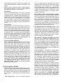
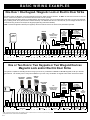
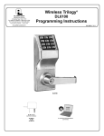
BASIC WIRING EXAMPLES
One Door / One Keypad / Magnetic Lock or Electric Door Strike
As shown below, the Magnetic Lock and Fail-Safe Electric Door Strike wiring are identical. Do NOT use Fail-Secure devices for fire exit
doors! In the event of power loss, Fail-Secure devices remain "secure" (locked).
The keypad interrupts MAG LOCK (or Fail-Safe Electric Door Strike) power upon a successful User Code entry (or Prox Card presentation), initiating "Pass Time" (time the door remains unlocked). The default Pass Time is 3 seconds, but you can change this time to 10 or
15 seconds using Functions 52-54 (see the keypad programming instructions WI1855).
TSD = Transient Suppression Device (two supplied): Mount the TSD as close to the device to be protected as possible.
MAG LOCK
(OR
FAIL-SAFE
ELECTRIC
DOOR
STRIKE)
NETPDK
N/C
Emergency Exit
Switch (or Fire
Panel Relay)
HI D
HID CORPORATION
ELECTRIC DOOR
STRIKE
(FAIL-SECURE)
NOT FOR FIRE EXITS
TSD*
Door
Position
Contact
TSD*
WO
W1
PWR
GND
WIEGAND INPUT
T1
T2
T3
T4
T5
T6
T7
T8
RED
LED
GRN
LED
SNDR
DRIVE
(+)
T9
T10
T11
T12
(–)
KYPD PWR
T13
Green
WOA
Jumper
Wire
Yellow
AC IN
Black
Red
EGND
N/O
Momentary
Switch
TX
(YEL)
RX
(GRN)
N/O
T14
T15
T16
N/C
COM
AUX RELAY
T17
T18
LOCK
PWR
(+)
COM
N/O
MAIN RELAY
LOCK
PWR
(–)
T19
T20
T21
T22
T23
N/C
DOOR
POSITION
CONTACT
T24
REMOTE
RELEASE
INPUT
T25
T26
T27
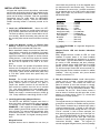
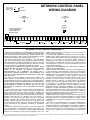
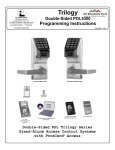
One or Two Doors / Two Keypads or Two Wiegand Devices
Magnetic Lock and/or Electric Door Strike
The system is capable of controlling two doors using up to two of any combination of NETDK or NETPDK keypads, PLUS up to two Wiegand devices. Two auxiliary Form-C relays are available for up to two of any combination of magnetic locks and/or electric door strikes.
SECONDARY
WIEGAND**
PRIMARY
WIEGAND**
PRIMARY
NETDK
MAG LOCK
(OR
FAIL-SAFE
ELECTRIC
DOOR
STRIKE)
SECONDARY
NETPDK
N/C
Emergency Exit
Switch (or Fire
Panel Relay)
T5
T6
T7
T8
SNDR
DRIVE
(+)
T9
T10
T11
T12
(–)
KYPD PWR
T13
Green
T4
TX
(YEL)
RX
(GRN)
N/O
T14
T15
T16
N/C
COM
AUX RELAY
*TSD = Transient Suppression Device (two supplied): Mount the TSD as close to the device to be protected as possible.
**Example device shown: HID ProxPoint® Plus Model 6005B.
10
TSD*
Door
Position
Contact
N/O
MAIN RELAY
LOCK
PWR
(–)
DOOR
POSITION
CONTACT
T21
T22
T23
N/O
Momentary
Switch
Jumper
Wire
Yellow
T3
GRN
LED
Black
T2
RED
LED
Red
T1
Yellow (Beeper)
GND
Orange (Green LED)
PWR
WIEGAND INPUT
(FAIL-SECURE)
NOT FOR FIRE EXITS
TSD*
Brown (Red LED)
W1
Black (- Ground)
WO
Red (+ DC)
WOA
White (Data 1)
AC IN
Green (Data 0)
Green (Data 0)
EGND
ELECTRIC DOOR
STRIKE
T17
T18
LOCK
PWR
(+)
COM
T19
T20
N/C
T24
T25
REMOTE
RELEASE
INPUT
T26
T27
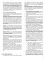
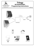
NOTES
11
4AH or 7AH
Rechargeable
Battery +12V.
E3
NETWORX CONTROL PANEL
WIRING DIAGRAM
(+) RED
E4
(–) BLACK
GREEN
AC POWER LED
LD2
GREEN
ACTIVITY LED
LD1
RESET
BUTTON
S2
AC IN, 16.5V/60HZ VIA TRF14
CLASS 2 TRANSFORMER
DO NOT CONNECT TO
SWITCHED OUTLET.
EGND
AC IN
WOA
WO
W1
PWR
GND
WIEGAND INPUT
T1
T2
T3
T4
T5
T6
T7
T8
RED
LED
GRN
LED
SNDR
DRIVE
(+)
T9
T10
T11
T12
(–)
KYPD PWR
T13
TX
(YEL)
RX
(GRN)
N/O
T14
T15
T16
N/C
COM
AUX RELAY
T17
T18
LOCK
PWR
(+)
COM
N/O
MAIN RELAY
LOCK
PWR
(–)
T19
T20
T21
T22
T23
N/C
DOOR
POSITION
CONTACT
T24
T25
REMOTE
RELEASE
INPUT
T26
T27
ALARM LOCK LIMITED WARRANTY
ALARM LOCK SYSTEMS, INC. (ALARM LOCK) warrants its products
to be free from manufacturing defects in materials and workmanship for
24 months following the date of manufacture. ALARM LOCK will, within
said period, at its option, repair or replace any product failing to operate
correctly without charge to the original purchaser or user.
This warranty shall not apply to any equipment, or any part thereof,
which has been repaired by others, improperly installed, improperly
used, abused, altered, damaged, subjected to acts of God, or on which
any serial numbers have been altered, defaced or removed. Seller will
not be responsible for any dismantling or reinstallation charges.
THERE ARE NO WARRANTIES, EXPRESS OR IMPLIED, WHICH
EXTEND BEYOND THE DESCRIPTION ON THE FACE HEREOF.
THERE IS NO EXPRESS OR IMPLIED WARRANTY OF
MERCHANTABILITY OR A WARRANTY OF FITNESS FOR A
PARTICULAR PURPOSE. ADDITIONALLY, THIS WARRANTY IS IN
LIEU OF ALL OTHER OBLIGATIONS OR LIABILITIES ON THE PART
OF ALARM LOCK.
Any action for breach of warranty, including but not limited to any
implied warranty of merchantability, must be brought within the six
months following the end of the warranty period. IN NO CASE SHALL
ALARM LOCK BE LIABLE TO ANYONE FOR ANY CONSEQUENTIAL
OR INCIDENTAL DAMAGES FOR BREACH OF THIS OR ANY
OTHER WARRANTY, EXPRESS OR IMPLIED, EVEN IF THE LOSS
OR DAMAGE IS CAUSED BY THE SELLER'S OWN NEGLIGENCE
OR FAULT.
In case of defect, contact the security professional who installed and
maintains your security system. In order to exercise the warranty, the
product must be returned by the security professional, shipping costs
prepaid and insured to ALARM LOCK. After repair or replacement,
ALARM LOCK assumes the cost of returning products under warranty.
ALARM LOCK shall have no obligation under this warranty, or
otherwise, if the product has been repaired by others, improperly
installed, improperly used, abused, altered, damaged, subjected to
accident, nuisance, flood, fire or acts of God, or on which any serial
numbers have been altered, defaced or removed. ALARM LOCK will
not be responsible for any dismantling, reassembly or reinstallation
charges.
This warranty contains the entire warranty. It is the sole warranty and
any prior agreements or representations, whether oral or written, are
either merged herein or are expressly canceled. ALARM LOCK neither
assumes, nor authorizes any other person purporting to act on its
behalf to modify, to change, or to assume for it, any other warranty or
liability concerning its products.
In no event shall ALARM LOCK be liable for an amount in excess of
ALARM LOCK's original selling price of the product, for any loss or
damage, whether direct, indirect, incidental, consequential, or otherwise
arising out of any failure of the product. Seller's warranty, as
hereinabove set forth, shall not be enlarged, diminished or affected by
and no obligation or liability shall arise or grow out of Seller's rendering
of technical advice or service in connection with Buyer's order of the
goods furnished hereunder.
ALARM LOCK RECOMMENDS THAT THE ENTIRE SYSTEM BE
COMPLETELY TESTED WEEKLY.
Warning: Despite frequent testing, and due to, but not limited to, any
or all of the following; criminal tampering, electrical or communications
disruption, it is possible for the system to fail to perform as expected.
ALARM LOCK does not represent that the product/system may not be
compromised or circumvented; or that the product or system will
prevent any personal injury or property loss by burglary, robbery, fire or
otherwise; nor that the product or system will in all cases provide
adequate warning or protection. A properly installed and maintained
alarm may only reduce risk of burglary, robbery, fire or otherwise but it
is not insurance or a guarantee that these events will not occur.
CONSEQUENTLY, SELLER SHALL HAVE NO LIABILITY FOR ANY
PERSONAL INJURY, PROPERTY DAMAGE, OR OTHER LOSS
BASED ON A CLAIM THE PRODUCT FAILED TO GIVE WARNING.
Therefore, the installer should in turn advise the consumer to take any
and all precautions for his or her safety including, but not limited to,
fleeing the premises and allege police or fire department, in order to
mitigate the possibilities of harm and/or damage.
ALARM LOCK is not an insurer of either the property or safety of the
user's family or employees, and limits its liability for any loss or damage
including incidental or consequential damages to ALARM LOCK's
original selling price of the product regardless of the cause of such loss
or damage.
Some states do not allow limitations on how long an implied warranty
lasts or do not allow the exclusion or limitation of incidental or
consequential damages, or differentiate in their treatment of limitations
of liability for ordinary or gross negligence, so the above limitations or
exclusions may not apply to you. This Warranty gives you specific legal
rights and you may also have other rights which vary from state to
state.
Trilogy® is a registered trademark of Alarm Lock. ProxCard® and ProxKey® are trademarks of the HID© Corporation.. Microsoft® and Windows® are trademarks of their the Microsoft Corporation. All other trade-
marks and/or service marks used herein are the property of their respective owners.
12