1
INSTALLATION STEPS
All inputs and outputs, electric door strikes, card readers
and all other accessories should first be installed as detailed in the numbered steps below. Note: Do not apply
power until all wiring is complete. Both AC and battery
connections must be made before the NETWORXPANEL will function properly. After the NETWORXPANEL mounting location is selected, proceed as follows:
1. Install the NETWORXPANEL. Mount the NETWORXPANEL housing to a vertical surface indoors in
a dry location (within the secured side of the door).
The back-up battery must be located within the secure housing. Mount the housing using the two middle mounting holes and at least one bottom mounting
hole.
2. Install the Magnetic Lock(s) or Electric Door
Strike(s). Always mount the magnetic lock or electric
door strike on the protected side of the door.
Before installation, always check with local laws having jurisdiction concerning the installation of magnetic
locking devices. There may be strict limitations with
regard the installation of magnetic or similar exit door
locking devices. Local laws may require the installation of electrically separate panic hardware to ensure
the door can be opened in the event of an emergency.
Door lock outputs can operate DC-powered locking
devices such as magnetic door locks or other electromechanical locks and can be configured to operate in
"Fail Secure" (which remain locked when power fails)
or "Fail Safe" (which unlock when power fails) configurations.
control both entry and exit) or on two separate doors
(to control access in one direction only). The text below indicates the correct wire / terminal connections
for an example device, the "HID ProxPro with Keypad
Model 5355" when only one device is wired to the
NETWORXPANEL:
HID 5355 Wires
NETWORXPANEL Terminals
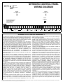
Red (DC+)...............................(T7) PWR
Black (GND) ...........................(T8) GND
Green (Data "0") ....................(T5) WO
White (Data "1") .....................(T6) W1
Violet (DATA RTN).................(Not Used)
Orange (Green LED)..............(T10) GRN LED
Brown (Red LED)...................(T9) RED LED
Yellow (Beeper) .....................(T11) SNDR DRIVE
Blue (Hold) .............................(Not Used)
--- (COM) .................................(Not Used)
--- (Tamper) ............................(Not Used)
See SPECIFICATIONS for supported Wiegand device models.
Wiegand Device LED and Sounder Indications
(Optional)
Many Wiegand devices include an LED for visual
feedback of system status or for visual feedback
when access credentials are presented to or swiped
in the reader. See the table below for examples of
the variety of LED indications and their meanings.
For the example device (HID ProxPoint Plus Model
6005B), wire the brown "Red LED" wire to terminal
T9, wire the orange "Green LED" wire to terminal T10.
Many Wiegand devices include a sounder for audible
feedback. Wire the sounder wire (some labeled
"beeper") to terminal T11.
Example: For normally energized door locks (such
as a magnetic lock that locks the door when energized), connect ground to terminal T23, place a
jumper wire between terminal 19 and terminal 20,
then connect the positive door lock wire to terminal
T21. See wiring diagrams for both normally energized and de-energized door locks. The NETWORXPANEL can supply a constant maximum 12VDC @
1.5A. Relay contacts are rated 8A @ 30VAC or VDC.
4. Wire Door Position Contact. Install a door position
contact such as a magnet / contact reed switch or
push button contact. This contact will monitor the
status of the door (if door was left open or closed).
Door contacts must be hardwired directly to the NETWORXPANEL. Do not use wireless contacts. Wire
to terminals T24 and T25. Door Position Contact is
used to detect if the door was left open after a User
passes or to detect a door "kick-in" (if a closed and
locked door is forcibly opened).
3. Install Keypads and/or Wiegand Devices.
The NETDK and NETPDK keypads each have 4
wires (red, black, yellow and green); wire to terminals
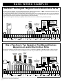
T12 through T15 as shown in the BASIC WIRING
EXAMPLES. If two keypads are used, connect each
wire in parallel (connect both keypad red wires to the
same terminal T12, connect both keypad black wires
to the same terminal T13, etc.) as shown in the wiring
diagram. See WI1881 for keypad mounting instructions.
Door Ajar
The keypad sounder (or Wiegand device) can be programmed to annunciate an audible warning that the
Door Position Contacts have remained open past a
certain programmed time. Typically, a door was left
open after a User passed through the door, or a door
"kick-in" occurred; in both of these examples, the
door status is entered into the log as a "door ajar" entry. The NETWORXPANEL Aux Relay can be programmed to energize for this "Door Ajar" event (see
Function 67 feature #12 in the keypad programming
instructions WI1855).
Note:
The keypad (or
sounder-equipped Wiegand device) used for passage
Wiegand Devices
Wiegand devices can be installed on one door (to
5