1
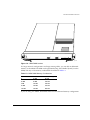
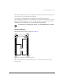
BlackDiamond Hardware
Installation Guide
Extreme Networks, Inc.
10460 Bandley Drive
Cupertino, California 95014
(888) 257-3000
http://www.extremenetworks.com
Published: September 1998
Part number: 121000-00 Rev. A
Copyright © Extreme Networks, Inc., 1998. All rights reserved. No part of this documentation may be
reproduced in any form or by any means or used to make any derivative work (such as translation,
transformation, or adaptation) without permission from Extreme Networks, Inc.
Extreme Networks, ExtremeWare, BlackDiamond, Summit, SummitLink, ExtremeWare Vista, Summit
Virtual Chassis, and the Extreme Networks logo are trademarks of Extreme Networks.
PACE is a trademark of 3Com Corporation. 3Com is a registered trademark of 3Com Corporation. All
other brand and product names are registered trademarks or trademarks of their respective holders.
ii
Contents
PREFACE
Introduction ix
Conventions x
Related Publications
1
xi
BLACKDIAMOND OVERVIEW
Summary of Features 1-1
Port Connections 1-2
Media Types and Distances 1-3
Full-Duplex 1-4
Network Configuration Example 1-4
BlackDiamond 6800 Components 1-6
BlackDiamond 6800 Power Supply 1-8
Power Supply LEDs 1-8
Management Switch Fabric Modules (MSMs)
MSM Behavior 1-10
MSM Memory 1-10
MSM LEDs 1-12
I/O Module Cards 1-12
G4X and G6X Modules 1-13
F32T Module 1-14
F32F Module 1-15
I/O Module LEDs 1-16
BlackDiamond 6800 Rear View 1-16
BlackDiamond6800 Fan Tray 1-18
1-9
iii
2
INSTALLATION
AND
SETUP
Following Safety Information 2-1
Determining the System Location 2-2
Installing the BlackDiamond 2-2
Powering On the System 2-7
Checking the Installation 2-7
Connecting Equipment to the Console Port
Logging In for the First Time 2-10
3
SERVICE
AND
2-8
MAINTENANCE
Following Safety Information 3-1
Removing and Replacing a Module Card 3-2
Removing and Replacing a Power Supply 3-3
Removing and Replacing the Fan Tray 3-4
Adding and Removing DIMMs 3-5
Adding and Removing GBICs 3-6
A
SAFETY INFORMATION
Important Safety Information
Power A-2
Power Cord A-2
Connections A-3
Lithium Battery A-3
B
TECHNICAL SPECIFICATIONS
INDEX
iv
A-1
Figures
1-1
1-2
1-3
1-4
1-5
1-6
1-7
1-8
2-1
2-2
2-3
2-4
2-5
2-6
3-1
3-2
3-3
3-4
BlackDiamond network configuration example 1-5
BlackDiamond 6800 1-7
Management Switch Fabric Module (MSM) 1-9
MSM DIMM sockets 1-11
G4X module and G6X module 1-13
F32T module 1-14
F32F module 1-15
BlackDiamond 6800 rear view 1-17
Rack-mount helper bracket 2-3
BlackDiamond chassis mounted in rack 2-4
Power supply bays 2-5
MSM with extended ejector/injector handles 2-6
Null-modem cable pinouts 2-9
PC-AT serial null-modem cable pinouts 2-10
BlackDiamond power supplies 3-3
Removing the fan tray 3-4
Adding a DIMM 3-5
GBIC connectors 3-6
v
vi
Tables
1
2
1-1
1-2
1-3
1-4
1-5
2-1
Notice Icons x
Text Conventions
x
Media Types and Distances
1-3
Power Supply LEDs
1-8
MSM DIMM Memory Combinations
MSM LEDs
1-12
I/O Module LEDs
1-16
Console Connector Pinouts 2-9
1-11
vii
viii
Preface
This Preface provides an overview of this guide, describes guide conventions, and lists
other publications that may be useful.
INTRODUCTION
This guide provides the required information to install the BlackDiamond™ system.
This guide is intended for use by network administrators who are responsible for
installing and setting up network equipment. It assumes a basic working knowledge of
• Local Area Networks (LANs)
• Ethernet concepts
• Ethernet switching and bridging concepts
• Routing concepts
• Simple Network Management Protocol (SNMP)
For information on configuring the BlackDiamond system, refer to the BlackDiamond
User Guide.
If the information in the “Release Notes” shipped with your switch differs from the
information in this guide, follow the “Release Notes.”
BLACKDIAMOND HARDWARE INSTALLATION GUIDE
IX
PREFACE
CONVENTIONS
Table 1 and Table 2 list conventions used throughout this guide.
Table 1: Notice Icons
Icon
Notice Type
Alerts you to...
Note
Important features or instructions.
Caution
Risk of personal injury, system damage,
or loss of data.
Warning
Risk of severe personal injury.
Table 2: Text Conventions
Convention
Description
Screen displays
This typeface represents information as it appears on the screen,
or command syntax.
Screen displays bold
This typeface represents commands that you type.
The words “enter”
and “type”
When you see the word “enter” in this guide, you must type
something, and then press the Return or Enter key. Do not press
the Return or Enter key when an instruction simply says “type.”
[Key] names
Key names appear in text in one of two ways:
■
Referred to by their labels, such as “the Return key” or “the
Escape key”
■
Written with brackets, such as [Return] or [Esc]
If you must press two or more keys simultaneously, the key
names are linked with a plus sign (+). Example:
Press [Ctrl]+[Alt]+[Del].
Words in italicized type
X
Italics emphasize a point or denote new terms at the place where
they are defined in the text.
BLACKDIAMOND HARDWARE INSTALLATION GUIDE
RELATED PUBLICATIONS
RELATED PUBLICATIONS
The BlackDiamond documentation set includes the following:
• BlackDiamond User Guide
• BlackDiamond Quick Reference Guide
• BlackDiamond “Release Notes”
Documentation for Extreme Networks products is available on the World Wide Web at
the following location:
• Extreme Networks home page http://www.extremenetworks.com/
BLACKDIAMOND HARDWARE INSTALLATION GUIDE
XI
PREFACE
XII
BLACKDIAMOND HARDWARE INSTALLATION GUIDE
1
BlackDiamond Overview
The BlackDiamond 6800 is a chassis-based system designed to be placed in the core of
your network. The BlackDiamond system is flexible and scalable, making it easy for you
to meet the changing requirements of your network. The combination of BlackDiamond
systems and Summit switches delivers a consistent end-to-end network solution that
provides nonblocking architecture, wire-speed switching, wire-speed IP routing, and
policy-based Quality of Service (QoS).
This chapter describes the following:
• BlackDiamond 6800 features
• Network configurations using the BlackDiamond 6800
• BlackDiamond 6800 components
SUMMARY
OF
FEATURES
The features of the BlackDiamond 6800 include the following:
• A 10-slot chassis that can be populated with up to 8 input/output (I/O) modules
and two Management Switch Fabric Modules (MSMs)
• I/O modules and MSMs are hot-swappable, and include Gigabit Ethernet or 10/100
Mbps Ethernet ports
• Redundant, load-sharing, hot-swappable power supplies
• Field-replaceable, hot-swappable fan tray
• Up to 256 switched 10/100 Mbps Ethernet ports
BLACKDIAMOND HARDWARE INSTALLATION GUIDE
1-1
BLACKDIAMOND OVERVIEW
• Up to 48 switched Gigabit Ethernet ports
• Fully nonblocking operation
— All ports transmit and receive packets at wire speed
• Autonegotiation for half- or full-duplex operation on 10/100 Mbps ports
• Load-sharing on multiple ports
• Virtual local area networks (VLANs), including support for IEEE 802.1Q
• Spanning Tree Protocol (STP) (IEEE 802.1D) with multiple STP domains
• Policy-based Quality of Service (QoS)
• Wire-speed Internet Protocol (IP) routing
• IP Multinetting
• Dynamic Host Configuration Protocol/Bootstrap Protocol (DHCP/BOOTP) Relay
• Routing Information Protocol (RIP) version 1 and RIP version 2
• Open Shortest Path First (OSPF) routing protocol
• Wire-speed IP multicast routing support
• Internet Group Multicast Protocol (IGMP) and IGMP snooping
• Distance Vector Multicast Routing protocol (DVMRP)
• IGMP snooping to control IP multicast traffic
• Console (RS-232) command-line interface (CLI) connection
• Telnet CLI connection
• ExtremeWare™ Vista™ Web-based management interface
• Simple Network Management Protocol (SNMP) support
PORT CONNECTIONS
The BlackDiamond 6800 supports the following I/O modules:
• G4X module
The G4X module has four Gigabit Ethernet ports, using standard Gigabit Interface
Connectors (GBICs). The G4X module supports 1000BASE-SX and 1000BASE-LX.
• G6X module
The G6X module has six Gigabit Ethernet ports, using standard Gigabit Interface
Connectors (GBICs). The G6X module supports 1000BASE-SX and 1000BASE-LX.
1-2
BLACKDIAMOND HARDWARE INSTALLATION GUIDE
SUMMARY
OF
FEATURES
• F32T module
The F32T module has 32 10/100 Mbps autosensing Ethernet ports, using standard
RJ-45 connectors. The F32T module supports 10BASE-T and 100BASE-TX.
• F32F module
The F32F module has 32 100 Mbps Ethernet ports, using standard MT-RJ connectors.
The F32F module supports 100BASE-FX in full-duplex mode.
Modules that use SX, LX, and FX interfaces contain Class 1 laser devices.
Invisible laser radiation can occur when open. Avoid direct eye exposure to
beam.
MEDIA TYPES
AND
DISTANCES
Table 1-1 describes the media types and distances for the different types of
BlackDiamond 6800 ports.
Table 1-1: Media Types and Distances
Standard
Media Type
Mhz/Km
Rating
Maximum
Distance
1000BASE-SX
50/125um Multimode Fiber
400
500 Meters
50/125um Multimode Fiber
500
550 Meters
62.5/125um Multimode Fiber
160
220 Meters
62.5/125um Multimode Fiber
200
275 Meters
50/125um Multimode Fiber
400
550 Meters
50/125um Multimode Fiber
500
550 Meters
62.5/125um Multimode Fiber
500
550 Meters
1000BASE-LX
10u Single-mode Fiber
5,000 Meters
10u Single-mode Fiber*
10,000 Meters
550/125um Multimode Fiber
(full-duplex operation)
2,000 Meters
52.5/125um Multimode Fiber
(full-duplex operation)
2,000 Meters
100BASE-TX
Category 5 UTP Cable (100Mbps)
100 Meters
10BASE-T
Category 3 UTP Cable (10Mbps)
100 Meters
100BASE-FX
*EXTREME NETWORKS
MAXIMUM DISTANCE OF
PROPRIETARY. CONNECTIONS BETWEEN TWO
10,000 METERS.
BLACKDIAMOND HARDWARE INSTALLATION GUIDE
EXTREME NETWORKS 1000BASE-LX
INTERFACES CAN USE A
1-3
BLACKDIAMOND OVERVIEW
For more information on 1000BASE-SX and 1000BASE-LX link characteristics,
refer to IEEE Draft P802.3z/D5.0, Table 38-2 and Table 38-6.
FULL-DUPLEX
The BlackDiamond system provides full-duplex support for all ports. Full-duplex
allows frames to be transmitted and received simultaneously and, in effect, doubles the
bandwidth available on a link. All 10/100 Mbps ports on the BlackDiamond 6800
autonegotiate for half- or full-duplex operation.
NETWORK CONFIGURATION EXAMPLE
The BlackDiamond can be used as a core network switch, a segment switch, or a server
switch. When used as a core network switch, the BlackDiamond performs
collapsed-backbone routing and switching at wire-speed, allowing it to handle the
growing influx of intranetwork and Internet traffic that travels between multiple
networks.
When used as a high-density segment switch in the wiring closet, the BlackDiamond
can aggregate the hierarchy of legacy hubs and switches that support desktop
connections. When the BlackDiamond is used to perform segment switching at Layer 3,
local traffic stays within the subnet and does not needlessly enter the core.
When used as a server switch, the BlackDiamond supports 10/100 Mbps segments and
Gigabit Ethernet segments, handling traffic to and from servers in the data center. This
application ensures sufficient bandwidth between servers and to segments. Conversely,
the BlackDiamond can support Gigabit Ethernet segments and 10/100Mbps server links
to optimize client-to-server traffic. Multiple 10, 100, and 1,000 Mbps switch ports can be
trunked into one logical link between the data centers, the network cores, and
high-performance servers.
Figure 1-1 shows an example of the BlackDiamond used in a network configuration.
1-4
BLACKDIAMOND HARDWARE INSTALLATION GUIDE
NETWORK CONFIGURATION EXAMPLE
Enterprise desktop
switching
Segment
switching
Core
routers
Server
switching
Core switching
BD_netX
Figure 1-1: BlackDiamond network configuration example
BLACKDIAMOND HARDWARE INSTALLATION GUIDE
1-5
BLACKDIAMOND OVERVIEW
BLACKDIAMOND 6800 COMPONENTS
The BlackDiamond 6800 system, shown in Figure 1-2, consists of the following
components:
• One 10-slot chassis with backplane
• Eight I/O module slots, labeled Slot 1 through Slot 8
• Two MSM module slots, labeled Slot A and Slot B
• Two power supplies
• One fan tray (accessed from the rear of the unit)
• One electromagnetic discharge (ESD) wrist strap receptacle
1-6
BLACKDIAMOND HARDWARE INSTALLATION GUIDE
BLACKDIAMOND 6800 COMPONENTS
MSM module
slots
I/O module slots
ESD wrist strap
connector
1
2
51010
3
51020
51010
4
A
B
51020
50014
50014
I/O module slots
5
6
52010
7
52010
8
52020
52020
G
DIA US
AT
ST
G
DIA US
AT
ST
G
DIA US
AT
ST
G
DIA US
AT
ST
R
ER
V
EN
R
ST
M
S
SY
R
ER
V
EN
R
ST
M
S
SY
G
DIA US
AT
ST
G
DIA US
AT
ST
G
DIA US
AT
ST
G
DIA US
AT
ST
1
1
1
1
1
9
17
25
1
9
17
25
1
9
17
25
1
9
2
2
2
2
2
10 18
26
2
10 18
26
2
10 18
26
2
10 18
3
3
3
3
3
11 19
27
3
11 19
27
3
11 19
27
3
11 19
4
4
4
4
4
12
20
28
4
12
20
28
4
12
20
28
4
12
20
28
5
5
5
13
21
29
5
13
21
29
5
13
21
29
5
13
21
29
6
6
6
14
22
30
6
14
22
30
6
14
22
30
6
14
22
30
7
15
23
31
7
15
23
31
7
15
23
31
7
15
23
31
8
16
24
32
8
16
24
32
8
16
24
32
8
16
24
32
= ACTIVITY
AMBER
= LINK OK
GREEN
FLASHING GREEN = DISABLED
= ACTIVITY
AMBER
= LINK OK
GREEN
FLASHING GREEN = DISABLED
= ACTIVITY
AMBER
= LINK OK
GREEN
FLASHING GREEN = DISABLED
= ACTIVITY
AMBER
= LINK OK
GREEN
FLASHING GREEN = DISABLED
= ACTIVITY
AMBER
= LINK OK
GREEN
FLASHING GREEN = DISABLED
1
1
2
2
3
3
CONSOLE
1
2
1
2
4
= ACTIVITY
AMBER
= LINK OK
GREEN
FLASHING GREEN = DISABLED
= ACTIVITY
AMBER
= LINK OK
GREEN
FLASHING GREEN = DISABLED
1
17
1
17
1
4
20
4
20
5
21
5
21
8
24
8
9
25
9
12
28
13
29
16
32
17
25
26
27
= ACTIVITY
AMBER
= LINK OK
GREEN
FLASHING GREEN = DISABLED
17
1
4
20
4
20
5
21
5
21
24
8
24
8
24
25
9
25
9
25
12
28
12
28
12
28
13
29
13
29
13
29
16
32
16
32
16
32
17
CONSOLE
4
MODEM
3
3
5
5
4
4
6
6
PCMCIA
MODEM
PCMCIA
DC OUT
DC OUT
AC IN
AC IN
Power supplies
BDchas
Figure 1-2: BlackDiamond 6800
BLACKDIAMOND HARDWARE INSTALLATION GUIDE
1-7
BLACKDIAMOND OVERVIEW
BLACKDIAMOND 6800 POWER SUPPLY
The BlackDiamond 6800 can have one or two A/C power supplies that use 220V power.
When two power supplies are present, the power is load-shared between the supplies
for enhanced longevity. The power supplies are hot-swappable.
SNMP traps are sent when one of the following occurs:
• A/C power failure
• Power supply failure
• Power supply is removed
POWER SUPPLY LEDS
Table 1-2 describes the light emitting diode (LED) behavior on the power supply.
Table 1-2: Power Supply LEDs
LED
Color
Indicates
A/C In
Green
Powered using 220V input
Amber
Powered using 110V input
Off
No power
Green
All D/C outputs are operational
Amber
One or more D/C outputs have failed
Off
No power
D/C Out
1-8
BLACKDIAMOND HARDWARE INSTALLATION GUIDE
BLACKDIAMOND 6800 COMPONENTS
MANAGEMENT SWITCH FABRIC MODULES (MSMS)
The MSM is the internal switch fabric for data that is being sent between I/O modules.
Each MSM has two CPUs for protocol processing, network management, and internal
switch fabric for processing data traffic between I/O modules. Up to two MSMs can be
installed in the BlackDiamond 6800 chassis for full redundancy. Using two MSMs, the
capacity of the BlackDiamond 6800 is doubled, and the system runs faster. Packet
throughput between I/O modules on the BlackDiamond 6800 is 32 Gbps when one
MSM is used, and 64 Gbps when two MSMs are present.
The MSMs must be installed in the center slots of the BlackDiamond 6800 chassis,
labeled Slot A and Slot B. Figure 1-3 shows the MSM.
50014
R
ER
V
EN
R
ST
M
S
SY
Module status LEDs
Module reset
Console port
CONSOLE
Modem port
MODEM
PCMCIA slot
PCMCIA
BD_MSM
Figure 1-3: Management Switch Fabric Module (MSM)
The MSM has the following ports:
• Console port (used to connect a terminal and perform local out-of-band
management)
• Modem port (used to connect a modem for remote access to the CLI)
• PCMCIA slot (for future development)
BLACKDIAMOND HARDWARE INSTALLATION GUIDE
1-9
BLACKDIAMOND OVERVIEW
MSM BEHAVIOR
The BlackDiamond 6800 can run with a single MSM installed. When a second MSM is
used, one of the MSMs is selected to be the master MSM, and the other becomes the
slave MSM.
The master MSM is responsible for upper-layer protocol processing and systemmanagement functions. For example, OSPF computation and SNMP functions are
performed by the master MSM. Packet handling is distributed among the four CPUs on
both MSMs.
Selection of the master MSM occurs automatically. The following scenarios describe the
selection process:
• When the BlackDiamond 6800 boots with both MSMs already installed, the MSM in
Slot A becomes the master.
• When the BlackDiamond 6800 boots with a single MSM (regardless of the slot), it is
selected as the master. If another MSM is added to the system while powered on, the
added MSM becomes the slave. The slave MSM can be inserted and de-inserted in
the chassis without disruption of network services.
If you de-insert the master MSM while the BlackDiamond 6800 is running, the slave
MSM does a soft reset and becomes the master MSM.
When you save the software configuration, it is saved to both MSMs. If you download a
new image, the image is downloaded to both MSMs.
MSM MEMORY
The MSM has two 168-pin DIMM sockets, and ships with one 64MB SDRAM module
installed, as shown in Figure 1-4. In the future, the memory capacity with be increased
by either replacing the 6 MB DIMM with a new one, or by adding a second DIMM to
the empty socket.
1-10
BLACKDIAMOND HARDWARE INSTALLATION GUIDE
PCMCIA
MODEM
CONSOLE
50014
SY M EN ER
S ST
R
R V
MSM
BLACKDIAMOND 6800 COMPONENTS
BD_SIMMs
Figure 1-4: MSM DIMM sockets
For larger network configurations and larger routing tables, you can add an additional
memory to the MSM. The MSM can be populated (using slots labelled J2 and J3 on the
MSM) with any of the memory combinations described in Table 1-3.
Table 1-3: MSM DIMM Memory Combinations
J2
J3
Total Memory
0
64 MB
64 MB
64 MB
64 MB
128 MB
0 MB
128 MB
128 MB
64 MB
128 MB
192 MB
128 MB
128 MB
256 MB
If you are using two MSMs, both MSMs must have the identical memory configuration.
BLACKDIAMOND HARDWARE INSTALLATION GUIDE
1-11
BLACKDIAMOND OVERVIEW
For more information on adding or removing DIMMs, refer to Chapter 3.
MSM LEDS
Table 1-4 describes the LED behavior on the MSM.
Table 1-4: MSM LEDs
LED
Color
Indicates
SYS
Green (blinking)
Normal operation
Amber (blinking)
Diagnostic test in progress
Amber
Diagnostic failure
Off
No power
Green
Master MSM
Amber
Slave MSM
Green
Environment (temperature, fan, power supply) is operating
properly
Amber
Environmental failure
Amber
Critical software error logged since power up
Off
Normal operation
MSTR
ENV
ERR
I/O MODULE CARDS
The BlackDiamond 6800 system has four I/O modules, as follows:
• G4X module
• G6X module
• F32T module
• F32F module
I/O modules can be inserted or de-inserted at any time, without causing disruption of
network services. No configuration information is stored on the I/O module; all
configuration information is stored on the MSM.
When the BlackDiamond 6800 is powered on, the system software generates a default
configuration for any slots that are occupied with I/O modules. The default
configuration allows the I/O module ports to participate in the VLAN default.
1-12
BLACKDIAMOND HARDWARE INSTALLATION GUIDE
BLACKDIAMOND 6800 COMPONENTS
The default configuration for the I/O module is not preserved unless you explicitly save
the information to nonvolatile RAM (NVRAM).
You can use the system software to configure the I/O module. You can also
pre-configure the parameters of a module that has not yet been inserted into the chassis.
The pre-configured information is used once the module is inserted. You must select a
module type for the slot before you can pre-configure the parameters.
For information on configuring I/O modules, see the BlackDiamond User Guide.
G4X
AND
G6X MODULES
The G4X and G6X modules are shown in Figure 1-5.
51010
2
3
4
Module status LEDs
Port status LEDs
51020
G
DIA US
T
STA
G
DIA US
T
STA
1
1
2
3
4
5
6
= ACTIVITY
AMBER
= LINK OK
GREEN
FLASHING GREEN = DISABLED
= ACTIVITY
AMBER
= LINK OK
GREEN
FLASHING GREEN = DISABLED
1
2
1
2
3
Gigabit
Ethernet
ports
4
3
5
4
6
BD_G4n6X
Figure 1-5: G4X module and G6X module
The G4X module has four Gigabit Ethernet ports. The G6X module has six Gigabit
Ethernet ports.
BLACKDIAMOND HARDWARE INSTALLATION GUIDE
1-13
BLACKDIAMOND OVERVIEW
All Gigabit Ethernet ports on these modules use standard GBIC connectors and support
1000BASE-SX and 1000BASE-LX. The default configuration of the G4X and G6X
modules is as follows:
• All ports are added to the default VLAN as untagged.
• All ports inherit the properties of the default VLAN (for example, protocol type,
VLANid, and so on).
• All ports are in auto-negotiation mode.
For supported media types and distances, refer to Table 1-1.
F32T MODULE
The F32T module, shown in Figure 1-6, has 32 10/100 Mbps Ethernet ports.
52010
Module status LEDs
G
DIA US
T
STA
1
9
17
25
2
10 18
26
3
11 19
27
4
12
20
28
5
13
21
29
6
14
22
30
7
15
23
31
8
16
24
32
Port status LEDs
= ACTIVITY
AMBER
= LINK OK
GREEN
FLASHING GREEN = DISABLED
1
17
4
20
5
21
8
24
9
25
12
28
13
29
16
32
10/100 Mbps
ports
BD_F32T
Figure 1-6: F32T module
1-14
BLACKDIAMOND HARDWARE INSTALLATION GUIDE
BLACKDIAMOND 6800 COMPONENTS
All F32T ports use standard RJ-45 connectors and support 10BASE-T and 100BASE-TX.
The default configuration of the F32T module is as follows:
• All ports are added to the default VLAN as untagged.
• All ports inherit the properties of the default VLAN (protocol type, VLANid, and so
on).
• All ports are in auto-negotiation mode allowing 10 Mbps, 100 Mbps, full-duplex, or
half-duplex operation.
F32F MODULE
The F32F module, shown in Figure 1-7, has 32 100 Mbps Ethernet ports.
52020
Module status LEDs
G
DIA US
T
STA
1
9
17
25
2
10 18
26
3
11 19
27
4
12
20
28
5
13
21
29
6
14
22
30
7
15
23
31
8
16
24
32
Port status LEDs
= ACTIVITY
AMBER
= LINK OK
GREEN
FLASHING GREEN = DISABLED
1
17
4
20
5
21
8
24
9
25
12
28
13
29
16
32
100 Mbps
ports
BD_F32F
Figure 1-7: F32F module
All F32F ports use standard MT-RJ connectors and support 100BASE-FX. The default
configuration of the F32F module is as follows:
• All ports are added to the default VLAN as untagged.
• All ports inherit the properties of the default VLAN (protocol type, VLANid, and so
on).
• All ports are in 100 Mbps, full-duplex mode.
BLACKDIAMOND HARDWARE INSTALLATION GUIDE
1-15
BLACKDIAMOND OVERVIEW
I/O MODULE LEDS
Table 1-5 describes the LED behavior on the I/O modules.
Table 1-5: I/O Module LEDs
LED
Color
Indicates
Status
Green blinking
Normal operation
Amber blinking
Configuration error, diagnostic
failure, or other severe card error
Off
No power
DIAG
Port x
Green
Normal operation
Amber blinking
Diagnostics in progress
Amber
Diagnostic failure
Green
Link up
Amber
Packet activity
Off
Link down
BLACKDIAMOND 6800 REAR VIEW
Figure 1-8 shows the rear view of the BlackDiamond 6800 switch.
The rear view of the BlackDiamond provides the following:
• Access to the fan tray
• The chassis serial number
• The device Ethernet MAC address
1-16
BLACKDIAMOND HARDWARE INSTALLATION GUIDE
BLACKDIAMOND 6800 REAR VIEW
Fan tray
DEPENDING UPON
PRODUCT CONFIGURATION
THIS EQUIPMENT MAY
CONTAIN
CAUTION
DISCONNECT ALL
POWER SUPPLY
INPUTS BEFORE
REMOVING BACK
PANEL FOR SERVICING
U
L
C
U
L
TUV Rheinland
GS
Gost
CE
VCCI
Ctick
This equipment has been tested and found to comply with the limits for a Class A digital device, pursuant to part 15 of FCC Rules.
Operation in a residential area may cause unacceptable interference to radio and TV receptions requiring the operator to take
whatever steps are necessary to correct the interference.
This Class A digital apparatus meets all requirements of the Canadian Interference-Causing Equipment Regulations.
Cet appareil numérique de la classe A respecte toutes les exigences du Réglement sur le matérial brouiller du Canada.
MADE IN USA
MODEL
PART No.
REFER TO INSTRUCTION
MANUAL FOR CORRECT
SELECTION OF POWER
CORD
131000-00 Rev. A
SERIAL No.
MAC Address
BD_rear
Figure 1-8: BlackDiamond 6800 rear view
BLACKDIAMOND HARDWARE INSTALLATION GUIDE
1-17
BLACKDIAMOND OVERVIEW
BLACKDIAMOND6800 FAN TRAY
The fan tray contains three individual fans, accessed from the rear of the chassis. The
fan status is monitored by the software for overheating conditions. All fan and
temperature failures trigger management alerts (for example SNMP traps, SYSLOG
messages, and so on). For more information on switch monitoring, refer to the
BlackDiamond User Guide.
Do not cover or obstruct the fan ventilation holes at the rear of the unit. Doing so
can result in an overheat condition and possible damage to the BlackDiamond
system. Thermal sensors will shut down the BlackDiamond if the internal
temperature exceeds 60 degrees Celsius.
1-18
BLACKDIAMOND HARDWARE INSTALLATION GUIDE
2
Installation and Setup
This chapter describes the following:
• How to decide where to install the BlackDiamond
• How to install the chassis in a rack
• How to install the power supply
• How to install module cards in the chassis
• How to connect equipment to the console port
• How to check the installation using the Power On Self-Test (POST)
FOLLOWING SAFETY INFORMATION
All service to BlackDiamond modules, fan tray, and power supplies should be
performed by trained service personnel, only.
Before installing or removing any components of the system, or before carrying
out any maintenance procedures, you must read the safety information provided
in Appendix A of this guide.
BLACKDIAMOND HARDWARE INSTALLATION GUIDE
2-1
INSTALLATION
AND
SETUP
DETERMINING
THE
SYSTEM LOCATION
The BlackDiamond is suited for use in a wiring closet or equipment room, where it can
be mounted in a standard 19-inch equipment rack. Mounting brackets are integrated
with the chassis.
When deciding where to install the BlackDiamond, ensure that
• The system is accessible and cables can be connected easily.
• Water or moisture cannot enter the chassis.
• Air-flow around the unit and through the vents at the rear of the chassis is not
restricted. A minimum of 3 inches is required (5 inches recommended) for clearance.
• Temperature operating limits of 0° to 40° C are not exceeded.
INSTALLING
THE
BLACKDIAMOND
The BlackDiamond can be mounted in a rack. The chassis is 15U high and fits in most
standard 19-inch racks.
The BlackDiamond chassis is shipped empty; you must install the power supply and
module cards after rack-mounting the empty chassis.
Rack-mount the chassis before installing any BlackDiamond components.
To install the BlackDiamond, follow these steps:
1 Mount the helper bracket in the rack using four appropriate rack-mounting screws,
as shown in Figure 2-1.
2-2
BLACKDIAMOND HARDWARE INSTALLATION GUIDE
INSTALLING
THE
BLACKDIAMOND
BDbrackt
Figure 2-1: Rack-mount helper bracket
2 Insert the empty chassis into the 19-inch rack and place it on the helper bracket.
3 Secure the empty chassis with eight suitable screws, as shown in Figure 2-2.
BLACKDIAMOND HARDWARE INSTALLATION GUIDE
2-3
INSTALLATION
AND
SETUP
1
2
3
4
A
B
5
6
7
8
BDinrack
Figure 2-2: BlackDiamond chassis mounted in rack
4 Once the chassis is secured, remove the helper bracket.
5 Install the first power supply in an empty power supply bay by following these
steps:
a Ensure that the power supply is right side up, and the locking handle is open.
b Slide the power supply into the bay.
c
2-4
Secure the power supply by rotating the locking handle up until it clicks in place,
and then tighten the screws using a #1 Phillips-head screwdriver.
BLACKDIAMOND HARDWARE INSTALLATION GUIDE
INSTALLING
THE
BLACKDIAMOND
6 To install a second power supply, remove the blank plate from the power supply bay
on the right of the chassis using a #1 Phillips-head screwdriver.
7 Install the second power supply, as shown in Figure 2-3, by repeating the procedure
described in Step 5.
DC OUT
AC IN
DC OUT
AC IN
BD_pwrx
Figure 2-3: Power supply bays
8 Prior to installing module cards into the BlackDiamond chassis, put on the ESD
wrist strap that is provided with the chassis, and connect the metal end to the
ground receptacle located on the top-left corner of the BlackDiamond front panel.
9 To install the MSM follow these steps:
a Ensure that the MSM is right side up (printed circuit board, or PCB, to the right),
the DIMM ejector locks are in the upright and locked position, and the
ejector/injector handles are extended, as shown in Figure 2-4.
BLACKDIAMOND HARDWARE INSTALLATION GUIDE
2-5
INSTALLATION
AND
SETUP
50014
R
ER
V
EN
R
ST
M
S
SY
CONSOLE
MODEM
PCMCIA
BDclips
Figure 2-4: MSM with extended ejector/injector handles
b Slide the MSM into the appropriate slot of the chassis (Slot A or Slot B), until it is
fully seated in the backplane.
Use the metal back panel, not the PCB to guide the MSM into the chassis.
Ensure that the DIMM ejector locks are closed before inserting the MSM.
When the MSM is fully seated in the chassis, the ejector/injector handles will
begin to close.
2-6
BLACKDIAMOND HARDWARE INSTALLATION GUIDE
POWERING ON
c
THE
SYSTEM
To secure the MSM in the chassis, close the ejector/injector handles by pushing
on them toward the center of the module card, and tighten the screws using a
#1 Phillips-head screwdriver.
d Repeat this procedure for the second MSM, if applicable.
The MSM can be installed in Slot A or Slot B only. The MSM does not fit in any
other chassis slots. Forceful insertion will damage the MSM module or
backplane connectors.
10 Install the I/O module by following these steps:
a Ensure that the I/O module is right side up, and the ejector/injector handles are
extended.
b Slide the I/O module into the appropriate slot of the chassis (Slots 1 through 8),
until it is fully seated in the backplane.
When the I/O module is fully seated in the chassis, the ejector/injector handles
will begin to close.
c
To secure the module in the chassis, close the ejector/injector handles by pushing
on them toward the center of the module card, and tighten the screws using a #1
Phillips-head screwdriver.
d Repeat this procedure for the additional I/O modules, if applicable.
The I/O module can be installed in any of the slots labeled Slot 1 through Slot 8
only. The I/O module does not fit in Slot A or Slot B. Forceful insertion will
damage the I/O module or backplane connectors
POWERING ON
THE
SYSTEM
To turn on power to the system, connect the AC power cable to the power supply and
then to the wall outlet. If you have installed two power supplies, connect both power
cables.
CHECKING
THE INSTALLATION
After turning on power to the BlackDiamond, each MSM performs a power-on self test
(POST) of its circuitry. The LED labeled “SYS” on the MSM blinks amber during the
POST. Once the MSM is operational, each I/O module performs a POST.
BLACKDIAMOND HARDWARE INSTALLATION GUIDE
2-7
INSTALLATION
AND
SETUP
For more information on the LEDs, refer to Chapter 1.
CONNECTING EQUIPMENT
TO THE
CONSOLE PORT
Connection to the console port is used for direct local management. The console port
settings are configured as follows:
• Baud rate — 9600
• Data bits — 8
• Stop bit — 1
• Parity — None
• Flow control — XON/XOFF
The terminal connected to the console port on the MSM must be configured with the
same settings. This procedure will be described in the documentation supplied with the
terminal.
2-8
BLACKDIAMOND HARDWARE INSTALLATION GUIDE
CONNECTING EQUIPMENT
TO THE
CONSOLE PORT
Appropriate cables are available from your local supplier. To make your own cables,
pinouts for a DB-9 male console connector are described in Table 2-1.
Table 2-1: Console Connector Pinouts
Function
Pin Number
Direction
DCD (data carrier detect)
1
In
RXD (receive data)
2
In
TXD (transmit data)
3
Out
DTR (data terminal ready)
4
Out
GND (ground)
5
-
DSR (data set ready)
6
In
RTS (request to send)
7
Out
CTS (clear to send
8
In
Figure 2-5 shows the pinouts for a 9-pin to 25-pin (RS-232) null-modem cable.
BlackDiamond
PC/Terminal
Cable connector: 9-pin female
Cable connector: 25-pin male/female
Screen Shell
3
TxD
2
RxD
5
Ground
7
RTS
8
CTS
6
DSR
1
DCD
4
DTR
1
3
2
7
4
20
5
6
8
Screen
RxD
TxD
Ground
RTS
DTR
CTS
DSR
DCD
BD25pin
Figure 2-5: Null-modem cable pinouts
BLACKDIAMOND HARDWARE INSTALLATION GUIDE
2-9
INSTALLATION
AND
SETUP
Figure 2-6 shows the pinouts for a 9-pin to 9-pin (PC-AT) null-modem serial cable.
BlackDiamond
PC-AT Serial Port
Cable connector: 9-pin female
Cable connector: 9-pin female
Shell Screen
1
DCD
2
RxD
3
TxD
4
DTR
5
Ground
6
DSR
7
RTS
8
CTS
Screen Shell
4
DTR
3
TxD
2
RxD
8
CTS
5
Ground
6
DSR
7
RTS
1
DCD
BD9pin
Figure 2-6: PC-AT serial null-modem cable pinouts
LOGGING IN
FOR THE
FIRST TIME
After the BlackDiamond has completed the POST, it is operational. Once operational,
you can log in to the system and configure an IP address for the default VLAN (named
default).
To manually configure the IP settings, perform the following steps:
1 Connect a terminal or workstation running terminal-emulation software to the MSM
console port.
2 At your terminal, press [Return] one or more times until you see the login prompt.
3 At the login prompt, enter the default user name admin to log on with administrator
privileges. For example:
login: admin
Administrator capabilities allow you to access all switch functions.
For more information on switch security, refer to the BlackDiamond User Guide.
2-10
BLACKDIAMOND HARDWARE INSTALLATION GUIDE
LOGGING IN
FOR THE
FIRST TIME
4 At the password prompt, press [Return].
The default name, admin, has no password assigned. When you have successfully
logged on to the system, the command-line prompt displays the system name (for
example, BlackDiamond6800> in its prompt.
5 Assign an IP address and subnetwork mask for VLAN default by typing
config vlan default ipaddress 123.45.67.8 255.255.255.0
Your changes take effect immediately.
6 Save your configuration changes so that they will be in effect after the next system
reboot, by typing
save
The configuration is saved to the configuration database of both MSMs.
For more information on saving configuration changes, refer to the BlackDiamond
User Guide.
7 When you are finished using the facility, log out by typing
logout
BLACKDIAMOND HARDWARE INSTALLATION GUIDE
2-11
INSTALLATION
2-12
AND
SETUP
BLACKDIAMOND HARDWARE INSTALLATION GUIDE
3
Service and Maintenance
This chapter describes the following:
• How to remove and replace a module card
• How to remove and replace a power supply
• How to remove and replace the fan tray
• How to add and remove DIMMs on the MSM
• How to add and remove a GBIC
FOLLOWING SAFETY INFORMATION
All service to BlackDiamond modules, fan tray, and power supplies should be
performed by trained service personnel, only.
Before installing or removing any components of the system, or before carrying
out any maintenance procedures, you must read the safety information provided
in Appendix A of this guide.
BLACKDIAMOND HARDWARE INSTALLATION GUIDE
3-1
SERVICE
AND
MAINTENANCE
REMOVING
AND
REPLACING
A
MODULE CARD
All BlackDiamond module cards (MSMs and I/O modules) are hot-swappable. You do
not need to power off the system to remove or insert a module card.
To remove and replace a module card, follow these steps:
1 Prior to installing module cards into the BlackDiamond chassis, put on the ESD
wrist strap that is provided with the chassis, and connect the metal end to the
ground receptacle located on the top-left corner of the BlackDiamond front panel.
2 Loosen the module card by unscrewing the screws using a #1 Phillips-head
screwdriver.
3 Rotate the ejector/injector handles to disengage the module card from the backplane.
4 Slide the module card out of the chassis.
5 Slide the new module card into the appropriate slot of the chassis (Slots 1 through
8), until it is fully seated in the backplane.
If you are adding or replacing an MSM, ensure that the DIMM ejector locks are
closed before sliding the MSM into the chassis.
6 When the module is fully seated in the chassis, the ejector/injector handles will
begin to close.
7 To secure the module in the chassis, close the ejector/injector handles by pushing on
them toward the center of the module card, and tighten the screws using a #1
Phillips-head screwdriver.
The I/O module can be installed in any of the slots labeled Slot 1 through Slot 8
only. The I/O module does not fit in Slot A or Slot B. The MSMs can be installed
in Slot A and Slot B. Forceful insertion will damage the module or backplane
connectors.
3-2
BLACKDIAMOND HARDWARE INSTALLATION GUIDE
REMOVING
REMOVING
AND
REPLACING
A
AND
REPLACING
A
POWER SUPPLY
POWER SUPPLY
BlackDiamond power supplies are hot-swappable. You can add a second power supply
without powering off the chassis. If you have two power supplies installed, you can
remove one of them without powering off the chassis.
To remove and replace a power supply, follow these steps:
1 Remove the power supply cord from the power supply and retention clip.
2 Unscrew the power supply using a #1 Phillips-head screwdriver.
3 Disengage the power supply by rotating the handle out and down.
The power supplies are shown in Figure 3-1.
DC OUT
AC IN
DC OUT
AC IN
BD_pwrx
Figure 3-1: BlackDiamond power supplies
4 Slide the power supply out of the chassis.
5 Ensure that the replacement power supply is right-side up, and the locking handle is
open.
6 Slide the power supply into the bay.
7 Secure the power supply by pushing down on the locking handle until it clicks in
place, and then tighten the screws using a #1 Phillips-head screwdriver.
BLACKDIAMOND HARDWARE INSTALLATION GUIDE
3-3
SERVICE
AND
MAINTENANCE
REMOVING
AND
REPLACING
THE
FAN TRAY
The BlackDiamond fan tray is hot-swappable. You do not need to turn off power to the
BlackDiamond to replace the fan tray. Access to the fan tray is from the rear of the
BlackDiamond chassis.
To remove and replace the fan tray, follow these steps:
1 Unscrew the ten screws securing the fan tray to the chassis, as shown in Figure 3-2.
BD_fanx
Figure 3-2: Removing the fan tray
2 Pull the fan tray straight back out of the chassis approximately ½ inch; this step
disconnects the power, causing the fans to stop.
3 Allow the fan blades to stop spinning before removing the fan tray completely.
Avoid personal injury. Keep hands away from rotating fan blades.
4 Insert the new fan tray into the bay.
5 Tighten the fan tray using the screws you removed in Step 1.
3-4
BLACKDIAMOND HARDWARE INSTALLATION GUIDE
ADDING
ADDING
AND
AND
REMOVING DIMMS
REMOVING DIMMS
To add a DIMM to the MSM, follow these steps:
1 Prior to removing or installing DIMMs on the MSM, put on the ESD wrist strap that
is provided with the chassis, and connect the metal end to the ground receptacle
located on the top-left corner of the BlackDiamond front panel.
2 Locate the DIMM sockets on the MSM.
3 Position the DIMM in the socket by ensuring that the gold fingers of the DIMM slip
into the connector and the keying notches align.
PCMCIA
MODEM
CONSOLE
50014
SY M EN ER
S ST
R
R V
MSM
4 Secure the DIMM by press down firmly until the DIMM is locked into the socket
and the ejector locks rotate into position, as shown in Figure 3-3.
BD_SIMMx
Figure 3-3: Adding a DIMM
BLACKDIAMOND HARDWARE INSTALLATION GUIDE
3-5
SERVICE
AND
MAINTENANCE
To remove a DIMM, follow these steps:
1 Prior to removing or installing DIMMs on the MSM, put on the ESD wrist strap that
is provided with the chassis, and connect the metal end to the ground receptacle
located on the top-left corner of the BlackDiamond front panel.
2 Disengage the DIMM by pulling back on the ejector locks located on either end of
the DIMM.
3 Pull the DIMM straight out of the socket.
Ensure the DIMM ejector locks are in the closed position prior to inserting the
MSM into the chassis.
ADDING
AND
REMOVING GBICS
GBICs can be added and removed from the BlackDiamond without powering off the
system. The two types of GBIC connectors are shown in Figure 3-4.
Connector A
Connector B
BD_GBICs
Figure 3-4: GBIC connectors
GBICs are a Class 1 laser device. Use only Extreme-approved devices.
To remove the GBIC connector labeled “Connector A,” gently squeeze the sides to
release it, and pull the GBIC out of the slot.
To remove the GBIC connector labeled “Connector B,” lift up on the front handle and
pull the GBIC out of the slot.
Ensure that the SC fiber-optic connector is removed from the GBIC prior to
removing the GBIC from the I/O module.
3-6
BLACKDIAMOND HARDWARE INSTALLATION GUIDE
ADDING
AND
REMOVING GBICS
Invisible laser radiation can occur when open. Avoid direct eye exposure to
beam.
To insert a GBIC connector, follow these steps:
1 Holding the GBIC by its sides, insert the GBIC into the slot on the I/O module.
2 Slide the GBIC as far back into the slot as possible, until you hear it click.
3 If the GBIC has a handle, push down on the handle to secure the GBIC in the slot.
BLACKDIAMOND HARDWARE INSTALLATION GUIDE
3-7
SERVICE
3-8
AND
MAINTENANCE
BLACKDIAMOND HARDWARE INSTALLATION GUIDE
A
Safety Information
IMPORTANT SAFETY INFORMATION
READ THE FOLLOWING SAFETY INFORMATION THOROUGHLY BEFORE
INSTALLING THE BLACKDIAMOND. FAILURE TO FOLLOW THIS SAFETY
INFORMATION MAY LEAD TO PERSONAL INJURY OR DAMAGE TO THE
EQUIPMENT.
• Installation, maintenance, removal of parts, and removal of the unit and components
must be done by qualified service personnel only.
Service personnel are persons having appropriate technical training and experience
necessary to be aware of the hazards to which they are exposed in performing a task
and of measures to minimize the danger to themselves or other persons.
• Install the unit only in a temperature- and humidity-controlled indoor area free or
airborne materials that may conduct electricity. Too much humidity may cause a fire.
Too much dryness may produce electrical shock and fire.
BLACKDIAMOND HARDWARE INSTALLATION GUIDE
A-1
SAFETY INFORMATION
POWER
This unit has two power inputs.
• Disconnect power before removing the back panel of the unit.
• The unit must be grounded.
• The unit must be connected to a grounded outlet to comply with European safety
standards.
• Do not connect the power supply unit to an A/C outlet without a ground
connection.
• The socket outlet must be near to the unit and easily accessible. You can only remove
power from the unit by disconnecting the power cord from the outlet.
• This unit operates under Safety Extra Low Voltage (SELV) conditions according to
IEC 950. The conditions are only maintained if the equipment to which it is
connected also operates under SELV conditions.
• The appliance coupler (the connector to the unit and not the wall plug) must have a
configuration for mating with an EN60320/IEC320 appliance inlet.
• France and Peru only
This unit cannot be powered from IT† supplies. If your supplies are of IT type, this
unit must be powered by 230V (2P+T) via an isolation transformer ratio 1:1, with the
secondary connection point labeled Neutral, connected directly to ground.
POWER CORD
• This must be approved for the country where it is used:
USA and
Canada
• The cord set must be UL-approved and CSAcertified.
• The minimum specification for the flexible cord is
No. 16 AWG (1.5 mm2), Type SV or SJ, 3-conductor.
• The cord set must have a rated current capacity of
at least 10A.
• The attachment plug must be an Earth-grounding
type with a NEMA L6-20P (20A, 250V)
configuration.
A-2
BLACKDIAMOND HARDWARE INSTALLATION GUIDE
IMPORTANT SAFETY INFORMATION
Denmark
• The supply plug must comply with section
107-2-D1, standard DK2-1a or DK2-5a.
Switzerland
• The supply plug must comply with SEV/ASE 1011.
• If the power cord plug is unsuitable and must be replaced, you may find other
codings for the respective connections. Connect the power supply wires for the unit
according to the following scheme:
— Brown wire to the Live (Line) plug terminal, which may be marked with the
letter “L” or colored red.
— Blue wire to the Neutral plug terminal, which may be marked with the letter “N”
or colored black.
— Yellow/Green wire to the Ground plug terminal, which may be marked with the
letter “E” or the Earth symbol
or colored yellow/green.
CONNECTIONS
• Fiber Optic ports - Optical Safety. Never look at the transmit LED/laser through a
magnifying device while it is powered on. Never look directly at the fiber TX port
and fiber cable ends when they are powered on.
• CLASS 1 LASER DEVICE
LITHIUM BATTERY
• The battery in the bq4830/DS1644 device is encapsulated and not user-replaceable.
The battery is located on the MSM motherboard.
• If service personnel disregard the instructions and attempt to replace the
bq4830/DS1644, replace the lithium battery with the same or equivalent type, as
recommended by the manufacturer.
Caution: There is danger of personal injury and explosion if battery is improperly
discarded. Do not discard the battery in fire or near heat. Always dispose of used
batteries according to the battery manufacturer’s instructions.
• Disposal requirements vary by country and by state.
• Lithium batteries are not listed by the Environmental Protection Agency (EPA) as a
hazardous waste. Therefore, they can typically be disposed of as normal waste.
BLACKDIAMOND HARDWARE INSTALLATION GUIDE
A-3
SAFETY INFORMATION
• If you are disposing of large quantities, contact a local waste-management service.
• No hazardous compounds are used within the battery module.
• The weight of the lithium contained in each coin cell is approximately 0.035 grams.
• Two types of batteries are used interchangeably:
— CR chemistry uses manganese dioxide as the cathode material.
— BR chemistry uses poly-carbonmonofluoride as the cathode material.
A-4
BLACKDIAMOND HARDWARE INSTALLATION GUIDE
B
Technical Specifications
Physical Dimensions
Height 26.25 inches x Width: 17.32 inches x Depth: 18 inches
Weight — Empty chassis
60 pounds
Weight — Fully loaded chassis
170 pounds
Weight — Each power supply
30 pounds
Weight — Each module card
5 pounds
Environmental Requirements
Operating Temperature
0° to 40° C
Storage Temperature
-10° to 70° C
Operating Humidity
10% to 95% relative humidity, noncondensing
Standards
EN60068 (IEC68)
Safety
Agency Certifications
UL 1950 3rd Edition, listed
cUL listed to CSA 22.2#950-95
TUV GS mark & GOST safety approval to the following EN
standards:
BLACKDIAMOND HARDWARE INSTALLATION GUIDE
■
EN60950:1992/A3:1995 plus ZB/ZC Deviations
■
EN60825-1
B-1
TECHNICAL SPECIFICATIONS
Electromagnetic
Compatibility
FCC part 15 Class A
ICES-0003 A
VCCI Class 1
EN55022 Class A
EN50082 -1 (1997)
C-Tick mark to AS/NZS 3548:1995 Class A
Heat Dissipation
1225W maximum (4185 BTU/hr maximum)
Power Supply
AC Line Frequency
47Hz to 63Hz
Input Voltage Options
180 VAC to 264 VAC, auto-ranging
Current Rating
200-240 VAC 10 A
B-2
BLACKDIAMOND HARDWARE INSTALLATION GUIDE
Index
A
air-flow requirements 2-2
B
BlackDiamond
air-flow requirements 2-2
components 1-6
configuration example 1-4
console port 1-9
dimensions B-1
features 1-1
I/O modules 1-12
installing 2-2
MAC address 1-16
media distances, supported 1-3
media types, supported 1-3
MSM, description 1-9
port connections 1-2
power supply 1-8
powering on 2-7
rear view 1-16
serial number 1-16
size B-1
C
cable types and distances 1-3
chassis rear view 1-16
components 1-6
configuration example 1-4
configuring IP settings 2-10
console port 1-9
connecting equipment to 2-8
settings 2-8
conventions
notice icons x
text x
D
DIMMs
description 1-10
installing and removing 3-5
F
F32F module 1-3, 1-15
F32T module 1-3, 1-14
fan tray
installing 3-4
removing 3-4
features 1-1
full-duplex 1-4
G
G4X module 1-2, 1-13
G6X module 1-2, 1-13
GBICs, installing and removing 3-6
H
helper bracket, installing 2-2
I
P
I/O modules
description 1-12
hot-swapping 1-12
installing 2-7, 3-2
LEDs 1-16
removing 3-2
installation
chassis 2-2
DIMMs 3-5
fan tray 3-4
GBICs 3-6
helper bracket 2-2
I/O modules 2-7, 3-2
MSM 2-5, 3-2
power supply 2-4, 3-3
rack-mounting 2-2
installing the system 2-2
IP settings, configuring 2-10
ports
connections 1-2
console port settings 2-8
installing and removing GBICs 3-6
MSM 1-9
power supply
installing 2-4, 3-3
LEDs 1-8
removing 3-3
voltage 1-8
powering on 2-7
power-on self test (POST) 2-7
L
LEDs
I/O modules 1-16
MSM 1-12
power supply 1-8
logging in 2-10
R
rack-mounting 2-2
related publications xi
S
safety information
English A-1
saving configuration 1-10
serial number 1-16
T
M
MAC address 1-16
Management Switch Fabric Module. See MSM
media types and distances 1-3
memory, MSM 1-10
MSM
booting 1-10
console port 1-9
console port settings 2-8
description 1-9
installing 2-5, 3-2
installing DIMMs 3-5
LEDs 1-12
master, slave functionality 1-10
memory 1-10
ports 1-9
removing 3-2
removing DIMMs 3-5
saving configuration 1-10
ii - INDEX
turning on 2-7
V
verifying the installation 2-7