1
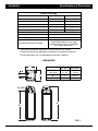
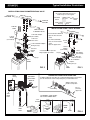
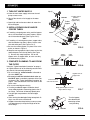
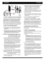
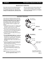
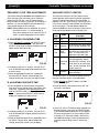
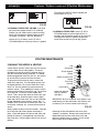
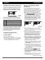
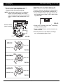
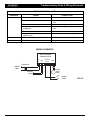
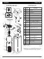
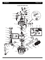
OWNER’S MANUAL
How to install, operate and maintain your
EcoWater Systems
Air Aspirated Iron Filter
Models ETF AIV-10
ETF AIV-12
Designed, Engineered &
Assembled in the U.S.A.
EcoWater Systems LLC
P.O. Box 64420, St. Paul, MN 55164-0420
1-800-86WATER
7336313 (Rev. A 12/10/12)
ECOWATER
Table of Contents
S Y S T E M S
TABLE OF CONTENTS
Page
Specifications & Dimensions . . . . . . . . . . . . . . . . . . . . . . . . . . . . . . . . . . . . . . . . . . . . . . . . . . . . . . . . . . . . . . . . . . . 3
Inspect Shipment . . . . . . . . . . . . . . . . . . . . . . . . . . . . . . . . . . . . . . . . . . . . . . . . . . . . . . . . . . . . . . . . . . . . . . . . . . . . 4
Safety Guides . . . . . . . . . . . . . . . . . . . . . . . . . . . . . . . . . . . . . . . . . . . . . . . . . . . . . . . . . . . . . . . . . . . . . . . . . . . . . . 4
Before Starting Installation . . . . . . . . . . . . . . . . . . . . . . . . . . . . . . . . . . . . . . . . . . . . . . . . . . . . . . . . . . . . . . . . . . . . 5
Typical Installation Illustrations . . . . . . . . . . . . . . . . . . . . . . . . . . . . . . . . . . . . . . . . . . . . . . . . . . . . . . . . . . . . . . . . . 6
Installation Instructions . . . . . . . . . . . . . . . . . . . . . . . . . . . . . . . . . . . . . . . . . . . . . . . . . . . . . . . . . . . . . . . . . . . . . . 7-8
Sanitizing Procedure . . . . . . . . . . . . . . . . . . . . . . . . . . . . . . . . . . . . . . . . . . . . . . . . . . . . . . . . . . . . . . . . . . . . . . . . . 9
Programming the Electronic Controller . . . . . . . . . . . . . . . . . . . . . . . . . . . . . . . . . . . . . . . . . . . . . . . . . . . . . . . 10-11
Controller Features / Options . . . . . . . . . . . . . . . . . . . . . . . . . . . . . . . . . . . . . . . . . . . . . . . . . . . . . . . . . . . . . . . 11-13
Routine Maintenance . . . . . . . . . . . . . . . . . . . . . . . . . . . . . . . . . . . . . . . . . . . . . . . . . . . . . . . . . . . . . . . . . . . . . . . 13
Troubleshooting . . . . . . . . . . . . . . . . . . . . . . . . . . . . . . . . . . . . . . . . . . . . . . . . . . . . . . . . . . . . . . . . . . . . . . . . . 14-16
Wiring Schematic . . . . . . . . . . . . . . . . . . . . . . . . . . . . . . . . . . . . . . . . . . . . . . . . . . . . . . . . . . . . . . . . . . . . . . . . . . 16
Repair Parts . . . . . . . . . . . . . . . . . . . . . . . . . . . . . . . . . . . . . . . . . . . . . . . . . . . . . . . . . . . . . . . . . . . . . . . . . . . . 17-19
Warranty . . . . . . . . . . . . . . . . . . . . . . . . . . . . . . . . . . . . . . . . . . . . . . . . . . . . . . . . . . . . . . . . . . . . . . . . . . . . . . . . . 20
2
ECOWATER
Specifications & Dimensions
S Y S T E M S
SPECIFICATIONS
Model ETF AIV-10
Model ETF AIV-12
Amount of Zeolite Media
1.0 cu. ft.
2.0 cu. ft.
Flow Rate
7 - 10 gpm
9 - 15 gpm
Model Code
HAAIF
Amount of Quartz Gravel
HAAIF
17 lbs.
Minimum Backwash Flow Rate
7 gpm*
Maximum Supply Water Pressure
Water Temperature Limits (min./max.)
Electrical Rating (transformer supplied)
29 lbs.
80 psi
40 - 120 °F
24V, 50/60 Hz
10 gpm*
Up to 10 ppm iron (except bacterial and
organically bound iron**) and 3 ppm
hydrogen sulfide at pH of 7.0 and higher.
Up to 2 ppm Manganese***
Contaminant Removal Limitations
*Well pump must be able to provide the minimum flow for 30+ minutes.
**Consult manufacturer for applications with bacterial or organically bound iron.
***Actual performance may vary depending on local water conditions.
DIMENSIONS
14"
14”
3-3/4"
3-3/4”
IN
IN
14"
14”
OUT
OUT
Nominal Mineral
Tank Size
A
ETF AIV-10
ETF AIV-12
57”
62-1/2”
10” dia. x
47” tall
50”
B
12” dia. x
54” tall
55-3/4”
TOP VIEW
VIEW
TOP
ININ- -OUT
OUT
A
44-3/4"
B
39-1/4"
SIDE VIEW
VIEW
SIDE
FRONT VIEW
FRONT
VIEW
3
FIG. 1
ECOWATER
Inspect Shipment & Safety Guides
S Y S T E M S
INSPECT SHIPMENT
The parts required to assemble and install the Air
Aspirated Iron Filter are included with the unit.
Thoroughly check the water filter for possible shipping
damage and parts loss. Also inspect and note any
damage to the shipping carton.
Remove and discard (or recycle) all packing materials.
To avoid loss of small parts, we suggest you keep the
small parts in the parts bag until you are ready to use
them.
SAFETY GUIDES
Recommended maximum allowable inlet water
pressure is 80 psi. Use a pressure reducing valve if
necessary. Be sure the addition of a pressure reducing valve will not reduce the flow to less than the 5
gallons per minute needed for backwash.
Follow the installation instructions carefully. Failure to
install the filter properly voids the warranty.
Before you begin installation, read this entire manual.
Then obtain all the materials and tools you will need
to make the installation.
This filter controller works on 24 Volt, 60 Hz electrical power only. Be sure to use the included transformer, and plug it into a nominal 120V, 60 Hz household outlet that is in a dry location only, grounded
and properly protected by an over-current device
such as circuit breaker or fuse.
Check local plumbing and electrical codes. The
installation must conform to them.
Use only lead-free solder and flux for all sweat-solder connections as required by state and federal
codes.
This system is not intended to be used for treating
water that is microbiologically unsafe or of unknown
quality without adequate disinfection before or after
the system.
Use care when handling the filter. Do not turn upside
down, drop, or set on sharp protrusions.
Do not locate the filter where freezing temperatures
occur. Do not attempt to filter water over 120°F.
Freezing, or hot water damage voids the warranty.
European Directive 2002/96/EC requires all
electrical and electronic equipment to be
disposed of according to Waste Electrical
and Electronic Equipment (WEEE) requirements. This directive or similar laws are in
place nationally and can vary from region to
region. Please refer to your state and local
laws for proper disposal of this equipment.
Avoid installing in direct sunlight. Excessive sun heat
may cause distortion or other damage to non-metallic
parts.
The filter requires a minimum water flow of 5 gallons
per minute at the inlet for backwash.
4
ECOWATER
Before Starting Installation
S Y S T E M S
WHERE TO INSTALL THE FILTER
TOOLS, PIPE & FITTINGS,
OTHER MATERIALS YOU WILL NEED
= Place the filter as close as possible to the pressure
tank (well system) or water meter (city water).
= Plastic inlet and outlet fittings included with the fil-
ter allow water flow equivalent to 1 inch nominal
pipe. To maintain full valve flow, 1” pipes to and
from the filter fittings are recommended. Do not
reduce the pipes to less than 3/4” size.
= Place the filter as close as possible to a floor
drain, or other acceptable drain point (laundry tub,
sump, standpipe, etc.). CAUTION: Drain water
exits the hose at a fast flow rate, and at water system pressure. Be sure the hose is fastened in
some manner to prevent ”whipping” and splashing
to prevent water damage to surrounding area.
= Use copper, brass or PEX plastic pipe and fittings.
= ALWAYS install the included check valve on the
INLET pipe, immediately upstream of the filter.
= Connect the filter to the main water supply pipe
= ALWAYS install the included bypass valve, or 3
UPSTREAM OF the water heater. DO NOT RUN
HOT WATER THROUGH THE FILTER. The temperature of water passing through the filter must
be less than 120°F.
shut-off valves. Bypass valves let you turn off
water to the filter for repairs if needed, but still
have water available to the house pipes.
= Drain hose 5/8” inside diameter minimum, with a
= Keep outside faucets on unfiltered water to con-
garden hose connection on one end, is needed for
the valve drain. See step 5 on page 8.
serve filtering capacity.
= Do not install the filter in a place where it could
= If a rigid valve drain is needed, to comply with
freeze. Damage caused by freezing is not covered by the warranty.
plumbing codes, you can buy the parts needed
(see page 6) to connect a 5/8” minimum copper
tubing drain.
= Put the filter in a place water damage is least likely
to occur if a leak develops. The manufacturer will
not repair or pay for water damage.
PLAN HOW YOU WILL INSTALL THE FILTER
= A 120 volt electric outlet, to plug the included
transformer into, is needed near the filter. The
transformer has an attached power cable. Be sure
the electric outlet and transformer are in an inside
location, to protect from wet weather.
You must first decide how to run in and out pipes to
the filter. Look at the house main water pipe at the
point where you will connect the filter. Is the pipe soldered copper, glued plastic, or threaded brass/galvanized? What is the pipe size?
= If installing in an outside location, you must take
the steps necessary to assure the filter, installation
plumbing, wiring, etc., are as well protected from
the elements, contamination, vandalism, etc., as
when installed indoors.
Now look at the typical installation illustration on page
6. Use it as a guide when planning your particular
installation. Be sure to direct incoming, unfiltered
water to the filter valve inlet fitting. The valve ports
are marked IN and OUT.
= Keep the filter out of direct sunlight. The sun's heat
may soften and distort plastic parts.
5
ECOWATER
Typical Installation Illustrations
S Y S T E M S
INSTALLATION USING ECOWATER BYPASS VALVE
Filtered
Water OUT
CROSS-OVER
Use if water supply flows from the left.
Include single or 3-valve bypass.
MAIN W
ATER
PIPE
UNFILTERED
WATER
Unfiltered
Water IN
120V AC
Outlet
1” Sweat
Adaptor
(not included)
For filtered water SERVICE:
1” NPT Male Adaptor
(not included)
TO FILTER
INLET
MAIN W
ATER
PIPE
-Open the inlet and outlet
valves
1” NPT Inlet
Check Valve*
For unfiltered BYPASS:
1” NPT Installation Adaptor*
O-Ring Seal (2)*
#7214383
Bypass
Valve
FROM FILTER
OUTLET
INSTALLATION USING 3-VALVE BYPASS
Unfiltered Water
to Outside Faucets
1”
Copper
Tube*
FILTERED
WATER
-Close the inlet and outlet
valves
-Open the bypass valve
BYPASS
Valve
OUTLET
INLET
Valve
Valve
1” Sweat
Adaptor
(not included)
1” NPT
Male Adaptor
(not included)
* Included with filter - Pipe and
fittings supplied by installer.
Clip (2)*
1” NPT Inlet
Check Valve*
Clip (2)*
1” NPT Installation
Adaptor*
Valve
INLET
O-Ring Seal (2)*
Valve
INLET
FIG. 2
Drain
Fitting
Pull out for
filtered water
“Service”
CONNECTING A RIGID VALVE DRAIN TUBE
To adapt a copper tube to the filter, buy a compression fitting (garden hose thread to
5/8” I.D. minimum tube and necessary tubing from your local hardware store.
Adaptor, garden hose
thread to compression
Push in for
Bypass
Valve
Drain
Hose
FIG. 3
Clip
5/8” I.D.
(minimum)
copper tube
Drain Fitting
To standpipe, sump, laundry
tub or other suitable drain.
1-1/2”
Air Gap
Valve
Drain
Hose
FLOOR
DRAIN
1-1/2””
Air Gap
STAND
PIPE
LAUNDRY
TUB
1-1/2” Air Gap
6
1-1/2”
Air Gap
SUMP
FIG. 4
ECOWATER
Installation
S Y S T E M S
1. TURN OFF WATER SUPPLY
Clip (2)
a. Close the main water supply valve near the well
pump or water meter.
1” Copper Tubes
(install in
filter valve or
Turbine bypass valve)
b. Shut off the electric or fuel supply to the water
heater.
OUTLET
c. Open high and low faucets to drain all water from
the house pipes.
Support
2. INSTALL BYPASS VALVE AND/OR
COPPER TUBES:
a. If installing a single bypass valve, push the bypass
valve, with lubricated o-ring seals in place, into the
valve inlet and outlet ports (See Figures 2 & 5).
INLET
- OR -
b. If installing a 3-valve bypass system, copper tubes,
with lubricated o-ring seals in place, into the valve
inlet and outlet ports (See Figures 3 & 5).
Clip (2)
Bypass
Valve
c. Be sure the turbine support is in place in the valve
outlet, as shown in Figure 6.
FIG. 5
d. Snap the two large plastic clips in place on the inlet
and outlet ports, from the top, down (See Figure
7). Be sure they snap into place. Pull on the
bypass valve, or copper tubes, to make sure they
are held securely in place.
Valve
Outlet
Turbine
Support
3. COMPLETE PLUMBING TO AND FROM
THE FILTER
FIG. 6
Using the “Typical Installation Illustration” on page 6
as a guide, observe all of the following cautions while
you connect inlet and outlet plumbing:
= Be sure incoming, unfiltered water is directed to
=
=
=
=
=
=
Clip
O-ring
the valve INLET port.
Be sure to install the included check valve on
the INLET pipe, immediately upstream of the filter,
as shown in the “Typical Installation Illustration” on
page 6. Note the direction of the flow arrow on the
check valve.
Be sure to install bypass valve(s).
If making a soldered copper installation, do all
sweat soldering before connecting pipes to the filter fittings. Torch heat will damage plastic parts.
Use pipe joint compound on all external pipe
threads.
When turning threaded pipe fittings onto plastic fittings, use care not to cross-thread.
Support inlet and outlet plumbing in some manner
(use pipe hangers) to keep the weight off of the
valve fittings.
Bypass valve or
copper tube
Cross section of
valve inlet or outlet
Snap clips into place between
larger diameter rings
FIG. 7
Turn the bypass
valve downward if
connecting to floor
level plumbing
INLET
7
OUTLET
FIG. 8
ECOWATER
Installation
S Y S T E M S
b. Place bypass valve(s) into “bypass” position. On a
single valve, slide the stem inward to BYPASS
(See Fig. 4 on page 6). On a 3 valve system,
close the inlet and outlet valves, and open the
bypass valve (See Fig. 3 on page 6).
Ground
Clamp
c. Fully open the house main water pipe shutoff valve.
Observe a steady flow from both opened faucets.
Inlet & Outlet
Pipes
d. Close both faucets.
e. Check your plumbing work for leaks and, if any are
found, fix right away. Be sure to observe previous
caution notes.
FIG. 9
f. Turn on the gas or electric supply to the water
heater. Light the pilot, if applicable.
4. INSTALL GROUND CLAMP (IF NEEDED):
If the home’s cold water piping is being used for electrical grounding, a 3 valve bypass system maintains
ground continuity. If you are using a single plastic
bypass valve, install the included ground clamp, as
shown In Figure 9, to maintain electrical ground continuity in the house cold water piping. Be sure the pipes
are clean, under the clamps, to assure good contact.
7. CONNECT TO ELECTRICAL POWER:
The filter works on 24 volt, 60 Hz electric power. The
included transformer changes standard 120 volt AC
house power to 24 volts. Plug the transformer into a
120V, 60 Hz electrical outlet. Be sure the outlet is
always “live” so it can not be switched off by mistake.
5. INSTALL VALVE DRAIN HOSE
8. PROGRAM THE CONTROLLER
a. Take a length of 5/8” inside diameter garden hose
and attach to the valve drain fitting (See Figure 4
on page 6).
See pages 10-11 for instructions to program the electronic controller.
9. START UP PROCEDURE
b. Locate the other end of the hose at a suitable drain
point (floor drain, sump, laundry tub, etc.). Check
and comply with local codes. Refer to Figure 4 on
page 6 if codes require a rigid pipe drain run.
a. Confirm that the filter’s main valve is in the “service”
position (“S” on the cam).
b. Place bypass valve(s) into “service”, EXACTLY as
follows:
IMPORTANT: Use high quality, thick wall hose that
will not easily kink or collapse. The filter will not backwash properly if water
cannot exit this hose during recharges.
= Single Bypass Valve: SLOWLY, pull the valve
stem outward to ”service” position, pausing several times to allow the filter to pressurize slowly.
c. Tie or wire the hose in place at the drain point.
Water pressure will cause it to whip during the
backwash portion of the recharge cycle. Also provide an air gap of at least 1-1/2” between the end
of the hose and the drain point. An air gap prevents possible siphoning of sewer water, into the
filter, if the sewer should back up.
= 3 Valve Bypass: Fully close the bypass valve
and open the outlet valve. SLOWLY, open the
inlet valve, pausing several times to allow the
filter to pressurize slowly.
c. Check all connections for leaks.
d. Push and hold the RECHARGE button until the filter starts a RECHARGE NOW cycle. Verify that
the valve advances to “backwash” (BW) position.
d. If raising the drain hose overhead is required to get
to the drain point, do not raise higher than 8 feet
above the floor. Elevating the hose may cause a
back pressure that could reduce backwash flow
and proper mineral bed cleaning.
e. Allow the unit to remain in “backwash” (BW) while
air is purged and water exits the drain line. Ensure
that the drain line is secure and will withstand the
mix of air and water exiting.
6. FLUSH PIPES AND TEST FOR LEAKS
f. Allow the unit to complete the 15 minute “backwash”
cycle and automatically advance to the “aspirate” (A)
position. Allow it to remain there as it aspirates air
into the mineral tank. After 75 minutes, the filter will
then automatically return to “service”. Start up is
complete.
CAUTION: To avoid water or air pressure damage to
filter inner parts, be sure to do the following steps exactly as listed:
a. Fully open two filtered water faucets, one cold and
one hot, nearby the filter.
8
ECOWATER
Description of Operation & Sanitizing
S Y S T E M S
DESCRIPTION OF OPERATION
Service water enters the filter and passes through air
captured at the top of the mineral tank. Dissolved
iron, manganese and sulphur are oxidized and then
removed by the media in the tank. When the system
recharges, it first backwashes the contaminants to the
drain, then empties the tank of water, replacing it with
air drawn through the aspirator. When the system
returns to "service", the water pressure will compress
the air in the mineral tank and leave an 8-14" head of
air on the top of the tank.
SANITIZING PROCEDURE
Care is taken at the factory to keep your water filter
clean and sanitary. Materials used to make the filter
will not infect or contaminate your water supply, and
will not cause bacteria to form or grow. However,
during shipping, storage, installing and operating,
bacteria could get into the filter or media. For this
reason, sanitizing as follows is suggested* when
installing.
Valve nozzle &
venturi assembly
Check valve
3/8” barb
1. Obtain pharmaceutical grade 12% hydrogen peroxide solution. One quart (0.95 L) is required for a
10" filter, 2 quarts (1.9 L) for a 12" filter.
2. Remove air inlet screen from check valve on the
valve’s nozzle & venturi assembly (See Figure 10).
Remove air
inlet screen
FIG. 10
3. Connect a length of 3/8 I.D. tubing to the barb on
the aspirator check valve (See Figure 11).
4. Insert the free end of the tubing into the hydrogen
peroxide container.
Valve nozzle &
venturi assembly
5. Push and hold the RECHARGE button until the filter starts a RECHARGE NOW cycle. The filter will
backwash for 15-17 minutes, then advance automatically to the “aspirate” position. It will draw the
hydrogen peroxide into the filter and pass it
through the zeolite media, cleaning and sanitizing
the media.
Check valve
3/8” barb
6. Allow the filter to draw air for the remainder of the
time in the “aspirate” cycle after the hydrogen peroxide has been drawn into the filter.
Connect 3/8” I.D.
tubing to barb
7. The filter will return to “service” automatically when
the “aspirate” cycle is complete.
8. Remove tubing and reinstall the aspirator inlet
screen onto the barbed fitting on aspirator check
valve.
9. Cleaning/sanitizing process is complete.
Place other end of tube in
hydrogen peroxide solution
*NOTE: Sanitizing is recommended by the Water Quality
Association for disinfecting. On some water supplies, they suggest periodic sanitizing.
FIG. 11
9
ECOWATER
Programming the Electronic Controller
S Y S T E M S
Display
UP button
DOWN
button
SELECT button
RECHARGE button
CONTROLLER SETTINGS REQUIRED
FIG. 12
B. SET DAYS BETWEEN RECHARGES
upon installation, and after an extended power outage.
1. If you completed the previous step, the word
“RECHARGE" should show in the display (See
Figure 15). Otherwise, press the SELECT button
several times until it does.
When the transformer is plugged into the electrical
outlet, a model code (HAAIF) and a test number
(example: J2.0), are briefly shown in the display.
Then the words “PRESENT TIME” appear and 12:00
PM begins to flash.
FIG. 15
2. The default setting is 1 day. This means that the
filter will recharge every day. To change the number of days between recharges, use the á UP or
â DOWN buttons to adjust from 1 to 99 days.
FIG. 13
A. SET PRESENT TIME OF DAY
Use the table below to determine the number of
days between recharges, based on the number of
people in the household and the iron ppm (parts
per million) in the water supply.
If the words “PRESENT TIME" do not show in the display, press the SELECT button several times until
they do.
Number of
People
1-3
4-7
FIG. 14
Iron (parts per million)
1-2
3 - 20
1 day
1 day
2 days
1 day
NOTE: If the water supply has high turbidity (sand,
silt, sediments, etc.) set to recharge more
often than the table shows.
1. Press the á UP or â DOWN buttons to set the
present time. Up moves the display ahead; down
sets the time back. Be sure AM or PM is correct.
3. When the desired number of days is displayed,
press the SELECT button, and the display will
change to show the “Recharge Time” screen.
NOTE: Press buttons and quickly release to slowly
advance the display. Hold the buttons down
for fast advance.
continued on next page
2. When the correct time is displayed, press the
SELECT button, and the display will change to
show the “Days between recharge” screen.
10
ECOWATER
S Y S T E M S
Programming (continued) & Controller Features / Options
C. SET RECHARGE START TIME
2. The filter’s default recharge start time is 12:00 AM.
This is normally a time of day when water is not
being used in the household. If you have a water
softener or another filter installed, the recharge
start times should be offset to assure adequate
water flow and pressure. For example, if the water
softener is set to begin recharge at 2:00 AM, set
the filter to start recharge at 12:00 AM, or 4:00 AM.
Use the á UP or â DOWN buttons to adjust the
recharge start time.
1. If you completed the previous step, the words
“RECHARGE TIME" should show in the display
(See Figure 16). Otherwise, press the SELECT
button several times until they do.
3. When the desired recharge time is displayed, press
the SELECT button, and the display will change to
show the normal run time display.
FIG. 16
CONTROLLER FEATURES / OPTIONS
NORMAL OPERATION
RECHARGE NOW
During normal operation, the present time of day
shows in the display.
For times when you expect to use more water than
usual, it may be desirable to perform a manually initiated recharge. To manually start a recharge cycle,
press and hold the RECHARGE button for a few seconds, until “RECHARGE NOW” flashes in the display.
The filter begins an immediate backwash. Once
started, you cannot cancel this recharge. Avoid using
hot water during this time, as the water heater will
refill with unfiltered water.
FIG. 17
POWER OUTAGE MEMORY
If electrical power to the filter’s control is lost, internal
memory will maintain most settings such as the days
between recharge and recharge time. However,
unless the power outage was very brief, the clock’s
present time will need to be reset. During a power
outage, the display will be blank and the filter will not
recharge. When electrical power is restored:
FIG. 18
VACATION CONTROL
1. Before going on vacation, or other long absence,
press (but do not hold) the RECHARGE button, so
that “VAC” begins to flash in the display. The timer
continues to keep time, but recharges will not occur,
saving water.
1. Check the display.
2a. If the present time is displayed steadily (not flashing), the controller did not lose time and you do
not need to reset the clock.
2b. If a time is flashing in the display, then the clock
needs to be reset to the correct present time.
See “Set Present Time of Day” on page 10. The
flashing display is to remind you to reset the
clock. If you do not reset the clock, then
recharges will most likely occur at the wrong time
of day.
FIG. 19
2. When you return, press the RECHARGE button
again. This cancels the flashing “VAC” and returns
the filter to normal service. You must remember to do
this, or the filter will not recharge.
NOTE: If the filter was recharging when power was
lost, it will finish the cycle when power returns.
11
ECOWATER
Controller Features / Options (continued)
S Y S T E M S
RECHARGE CYCLE TIME ADJUSTMENTS
AUXILIARY OUTPUT CONTROL
The default setting for backwash and aspirate times
of the recharge cycle are factory set for maximum
performance of the filter. Use the following procedures to check for correct cycle times, or to change, if
desired. It is recommended that only trained technicians should change the time settings.
The electronic controller’s auxiliary output may be
used to operate various types of external equipment,
such as a chlorine generator or chemical feeder. It
provides a 24V DC, up to 500 mA, current from terminal J4 on the electronic control board (see Schematic
on the next page). The table below explains the
choices available for when the auxiliary output will be
on during various portions of the recharge cycle:
NOTE: Fill and brine times are adjustable, but set at
the factory to zero. It is recommended to
leave these settings at zero, unless the filter is
used in a custom application by the installer.
SELECTION
A. ADJUSTABLE BACKWASH TIME
Remains off indefinitely.
CL
Chlorine
On during the brine draw portion
of the recharge (softeners only).
FS
Flow
Switch
CF
Chemical
Feeder
FR
Aspirate
BP
FIG. 20
2. The default setting is 15 minutes. Use the á UP
or â DOWN buttons to adjust backwash time from
0 to 99 minutes.
3. When the desired backwash time is displayed,
press the SELECT button, and the display will
change to show the next cycle time adjust screen.
AUXILIARY OUTPUT
FUNCTION
Off
OFF
1. Press and hold for 3 seconds the SELECT button,
until the display shows “000 - -“, then press the
SELECT button again to display the backwash time
adjust screen (See Figure 20).
NAME
Bypass
On during the entire recharge.
On when water is flowing past
the turbine (on units with a turbine). It will shut off 8 seconds after water flow stops.
After the set volume of water
has flowed past the turbine
(on units with a turbine), turns
on for the time set (see Steps
4 & 5, on the next page, to set
volume and time).
On during the aspirate portion
of the recharge.
The default is OFF. If you wish to change to one of
the other selections shown in the table above:
1. Press and hold the SELECT button until “000 - -”
shows in the display.
B. ADJUSTABLE ASPIRATE TIME
1. If you completed the previous step, the aspirate
time adjust screen should show in the display (See
Figure 21). Otherwise, press and hold for 3 seconds the SELECT button, until the display shows
“000 - -“, then press the SELECT button twice to
display the aspirate time adjust screen.
2. Press the SELECT button three times and “Ctrl"
will flash in the display.
FIG. 22
3. Use the á UP or â DOWN buttons to display the
desired selection, then press the SELECT button.
If you selected anything other than CF, the display
will return to the normal run (time of day) screen.
If setting to CF (Chemical Feeder), there will be
two additional settings to make for operating the
chemical feeder in Steps 4 and 5, on the next
page.
FIG. 21
2. The default setting is 75 minutes. Use the á UP
or â DOWN buttons to adjust aspirate time from 0
to 99 minutes.
3. When the desired aspirate time is displayed, press
the SELECT button twice, and the display will
change to show the normal run time display.
12
ECOWATER
S Y S T E M S
Features / Options (continued) & Routine Maintenance
Then press the SELECT button to display the
screen shown in Fig. 24.
FIG. 23
FIG. 24
4. CHEMICAL FEEDER TRIP VOLUME: If you have
set the auxiliary output control to CF (Chemical
Feeder), you will need to set the volume of water
which must flow past the turbine before the auxiliary output is turned on. With the alternating
screens in Fig. 23 shown, use the á UP or
â DOWN buttons to set the trip volume, in gallons.
5. CHEMICAL FEEDER TIME: Use the á UP or
â DOWN buttons to set the length of time, in
seconds, that the auxiliary output will be turned on.
Then press the SELECT button to accept and
return to the normal run (time of day) screen.
ROUTINE MAINTENANCE
CLEANING THE NOZZLE & VENTURI
Cap
A clean nozzle & venturi (See Figure 25) is a necessity for the water filter to work properly. This small
component creates the suction to aspirate (bring air
into) the mineral tank during recharges. If it should
become plugged with sand, silt, dirt, etc., the water filter will not work to remove iron from the water.
O-ring Seal
Screen Support
Screen
Nozzle & Venturi Disc
Gasket
*Flow Plug
To get access to the nozzle & venturi, remove the
water filter’s top cover. Put the bypass valve(s) into
the bypass position. Be sure the water filter’s main
valve is in “service” position (no water pressure at
nozzle & venturi). Then, holding the nozzle & venturi
housing with one hand, unscrew the cap. Do not lose
the o-ring seal. Lift out the screen support and
screen. Then, remove the nozzle & venturi disc, gasket and flow plug. Wash the parts in warm, soapy
water and rinse in fresh water. Be sure to clean both
the top and bottom of the nozzle & venturi disc. If
needed, use a small brush to remove iron or dirt. Do
not scratch, misshape, etc., surfaces of the nozzle &
venturi.
Housing
Check Valve
*Install with lettered
side up, concave
side down.
IMPORTANT: Be sure small hole in the gasket is centered directly over the small hole in the nozzle & venturi housing. Be sure the numbers are facing up
FIG. 25
Gently replace all parts in the correct order. Lubricate
the o-ring seal with silicone grease and locate in
place. Install and tighten the cap by hand, while supporting the housing. Overtightening may break the
cap or housing. Put the bypass valve(s) into “service”
position.
Recharge the filter and advance the valve to the
“aspirate” (A) position. Remove the screen from the
barbed fitting on the inlet of the check valve and
determine whether there is suction. Put the screen
back in place when finished checking.
13
ECOWATER
Troubleshooting
S Y S T E M S
AUTOMATIC ELECTRONIC DIAGNOSTICS
MANUALLY INITIATED ELECTRONIC
DIAGNOSTICS
This filter has a self-diagnostic function for the electrical system. The computer monitors electronic components and circuits for correct operation. If a malfunction occurs, an error code appears in the display.
Use the following procedures to advance the filter
through the recharge cycles to check operation.
Remove the top cover faceplate assembly by unlocking the tabs and lifting, to observe cam and switch
operation during valve rotation (See Figure 28).
1. Press and hold for 3 seconds the SELECT button,
until one of the screens shown in Figure 27 is displayed. If the valve is in service, backwash or
aspirate position (observe markings on the valve
cam), the display should show “000 - -”, meaning
the position switch is open. When the valve is
moving, the display should show “000 - P”, meaning that the position switch is closed.
FIG. 26
The chart below shows the error codes that could
appear, and the possible malfunctions for each code.
Code
Possible Problems
Err01
Motor, Valve Position Switch
Err04
Valve Position Switch
Err03
Err05
Motor, Valve Position Switch, Wire Harness
Electronic Control Board (PWA)
FIG. 27
While an error code appears in the display, all buttons
are inoperable except the SELECT button. SELECT
remains operational so the service person can perform the Manually Initiated Electronic Diagnostics to
further isolate the problem.
2. Use the RECHARGE button to manually advance
the valve into each position and check correct switch
operation (See Figures 29-31).
3. While in the “aspirate” (A) position, check the nozzle & venturi by removing the screen from the
barbed fitting on the inlet of the check valve and
determining whether there is suction. Put the
screen back in place when finished checking.
TO REMOVE AN ERROR CODE:
1. Unplug the transformer.
2. Correct the problem.
4. While in this diagnostic screen, the following information is available and may be beneficial for various reasons. This information is retained by the
computer from the first time electrical power is
applied to the electronic controller.
3. Plug the transformer back in.
4. Wait for at least 8 minutes while the timer operates
the valve through an entire cycle. The error code
will return if the problem was not corrected.
a. Press the á UP button to display the number of
days this electronic control has had electrical
power applied.
b. Press the â DOWN button to display the number of automatic or manual recharges initiated
by this electronic control since the model code
number was entered.
5. Press the SELECT button and hold in for 3 seconds until the model code shows in the display.
The model code should be “HAAIF”. If the wrong
number shows, the filter will operate on incorrect
configuration data.
6. To change the code number - Press the á UP or
â DOWN button until the correct code shows.
continued on the next page
14
ECOWATER
Troubleshooting (continued)
S Y S T E M S
RESETTING TO FACTORY DEFAULTS
7. To return to the present time display, press the
SELECT button. If the model code was
changed, make all controller settings.
To reset the electronic controller to its factory default
for all settings (time, days between recharges, etc.):
NOTE: If the electronic control is left in a diagnostic
display (or a flashing display when setting
times or hardness), present time automatically
returns if a button is not pressed within 4 minutes.
1. Press the SELECT button and hold it until the display changes twice to show “CODE” and the flashing model code.
FIG. 32
Position markers
(valve in service)
2. Press the á UP button (a few times, if necessary)
to display a flashing “SoS”.
3. Press the SELECT button, and the electronic controller will restart.
MOTOR
CAM
SERVICE
4. Set the present time, days between recharges,
etc., as described on pages 10 & 11.
FIG. 28
S
Valve Cam
Position Switch
FIG. 29
BACKWASH
BW
Valve Cam
Position Switch
FIG. 30
ASPIRATE
A
Valve Cam
Position Switch
FIG. 31
15
ECOWATER
Troubleshooting Guide & Wiring Schematic
S Y S T E M S
PROBLEM
Iron bleed
TROUBLESHOOTING GUIDE
CAUSE
1. Riser tube o-ring.
1. Reseat or replace riser o-ring.
3. Time clock set incorrectly.
3. Check and change time.
2. Over-running filter bed.
2. Increase recharge frequency and backwash
time.
4. Increase in iron, hydrogen sulfide or
manganese.
4. Increase recharge frequency and backwash
time.
5. Restricted drain line or drain flow control
Air in house lines
Water to drain
CORRECTION
5. Clear drain line or drain flow control.
6. Plugged nozzle & venturi - no suction in
aspirate cycle.
6. Clean nozzle & venturi (See Page 13).
1. Riser tube o-ring.
1. Reseat or replace riser o-ring.
1. Defective rotor disc and seals.
1. Replace rotor disc and seals.
WIRING SCHEMATIC
Back of Electronic
Controller (PWA)
AC
In
240VAC
60Hz
J4
Position/
Turbine
Motor
Transformer
24VAC
24VDC
Valve
motor
Auxiliary
Output
NO
NC
16
Position
switch
FIG. 33
ECOWATER
Repair Parts
S Y S T E M S
FILTER EXPLODED VIEW
FILTER PARTS LIST
1
19
Key
No.
7210478
Top Cover
3
7259927
Wire Harness
4
2
5
3
¢
6
9
10
7
Valve Assembly
See Pages 18 - 19
for parts
8
4
5
12
7
14
7308970
7211173
7274286
7211068
7211050
á
–
7112963
11
á
13
á
15
16
16
7210509
9
14
15
7336363
7331177
12
6
13
7275907
–
10
11
Description
1
2
20
Part No.
á
á
7335757
7105047
7092202
7113074
17
7336656
19
7336185
18
20
7124415
7248706
Transformer, 120 V to 24 V, 10 VA
Repl. Electronic Controller (PWA)
Faceplate (order decal below)
Decal, Faceplate
Support, Faceplate
Rim
Shroud, Model ETF 2100AIV-10
Shroud, Model ETF 2100AIV-12
Tank Neck Clamp Kit
(includes 2 ea. of Key Nos. 9 & 10)
Clamp Section (2 req.)
Retainer, Clamp (2 req.)
Distributor O-Ring Kit
(includes Key Nos. 11-13)
O-Ring, 2-7/8” x 3-1/4”
O-Ring, 13/16” x 1-1/16”
O-Ring, 2-3/4” x 3”
Top Distributor
Repl. Bottom Distributor
Repl. Mineral Tank, 10” x 47”,
Model ETF 2100AIV-10
Repl. Mineral Tank, 12” x 54”
Model ETF 2100AIV-12
Zeolite Media, 1 cu. ft.
Gravel, 17 lbs.
Inlet Check Valve, 1”
Ground Clamp Kit
¢ Not illustrated
17
To order parts, call your local EcoWater dealer or go to
www.ecowater.com to locate a dealer in your area.
18
8
17
ECOWATER
Repair Parts
S Y S T E M S
VALVE EXPLODED VIEW
50
51
52
93
53
92
54
91
55
Flow Plug
Assembly
Assembled
View
56
90
89
88
58
59
94
57
70
60
87
61
73
66
86
67
Wear Strip
85
62
Seal
84
Cross-section
View
83
63
82
68
75
64
70
71
69
65
81
80
79
78
74
77
76
18
73
72
ECOWATER
Repair Parts
S Y S T E M S
VALVE PARTS LIST
Key
No.
Part No.
50
7224087
Screw, #8-32 x 1” (2 req.)
52
7231393
Motor Plate
51
53
54
55
56
57
58
59
7286039
0900857
7171250
7335024
7169180
7172793
7170288
7178202
7178210
–
7185487
61
á
60
62
63
64
65
á
á
á
á
á
66
7174313
68
7171187
67
7335058
69
7129889
71
7077642
70
72
7089306
7271204
Key
No.
Description
73
Motor (incl. 2 ea. of Key No. 50)
Bearing
Clip, Drain
Flow Plug, 7 gpm,
Model ETF 2100AIV-10
Retainer, Nozzle & Venturi
7171145
77
7170319
79
7336193
81
O-Ring, 15/16” x 1-3/16”
7081201
76
80
Drain Hose Adaptor
O-Ring, 1-1/16” x 1-5/16” (2 req.)
7078240
78
Cam & Gear
7336208
7120526
7292323
–
7085247
Flow Plug, 10 gpm,
Model ETF 2100AIV-12
82
7081104
O-Ring, 5/8” x 13/16”
84
83
Seal Kit (includes Key Nos. 60-65)
O-Ring, 1-1/8” x 1-1/2”
85
O-Ring, 4-1/2” x 4-7/8”
86
Rotor Seal
87
Seal
88
Seal, Nozzle & Venturi
89
Bearing, Wave Washer
90
Rotor & Disc
Plug, Drain Seal
Clip (2 req.)
1” NPT Threaded Adaptor
7114533
7204362
7146043
7167659
7170262
7199729
7175199
7171161
7172997
93
7140738
94
Copper Tube, 1”
1148800
91
92
Spring
Description
7311127
74
75
Screw, #6-20 x 3/8” (3 req.)
Part No.
7305150
7214383
Turbine Support & Shaft
Valve Body
O-Ring, 1/4” x 3/8” (2 req.)
Air Inlet Screen
Aspirator Check Valve
Elbow, 90°
O-Ring, 3/16” x 7/16”
Nozzle & Venturi Assembly
(includes Key Nos. 82-88)
Housing, Nozzle & Venturi
Flow Plug, .3 gpm
Nozzle & Venturi Gasket Kit
Gasket Only
Screen
Screen Support
O-Ring, 1-1/8” x 1-3/8”
Cap
Wave Washer
Valve Cover
Screw, #10 x 2-5/8” (8 req.)
Switch
Screw, #4-24 x 3/4” (2 req.)
Bypass Valve Ù (includes 2 ea. of
Key Nos. 70 & 73)
Ù Optional parts, not included with filter
To order parts, call your local EcoWater dealer or go to
www.ecowater.com to locate a dealer in your area.
19
ECOWATER
Warranty
S Y S T E M S
LIMITED WARRANTY
EcoWater Systems LLC Advantage Warranty
Series ETF AIV Water System
Congratulations! You have just purchased the highest quality water conditioning product on the market. To register your warranty, complete the enclosed Warranty Registration Card and mail it within 30 days of purchase.
To whom is this warranty extended?
EcoWater Systems LLC warrants its products to the original owner and guarantees that the products will be free from defects
in materials and workmanship from the original date of installation.
How does my warranty work?
If, during the respective warranty period, a part proves, after inspection by EcoWater, to be defective, EcoWater will, at its sole
option repair or replace that part at no charge, other than normal shipping, installation or service charges.
What is covered by the warranty?
EcoWater Systems LLC guarantees that,
for the LIFETIME of the original owner, the MINERAL TANK will not rust, corrode, leak, burst, or in any other manner fail to perform its proper functions and that,
for a period of FIVE (5) YEARS after installation, the VALVE BODY will be free of defects in materials and workmanship and will
perform its proper function and that,
for a period of THREE (3) YEARS after installation, the ELECTRONIC FACEPLATE will be free of defects in materials and workmanship and will perform its normal functions, and that,
for a period of ONE (1) YEAR after installation, all other parts will be free of defects in materials and workmanship and will perform their normal functions.
How do I obtain warranty service?
Should you need service, your local, independent EcoWater Dealer is only a phone call away.
PHONE:____________________________________________________________
To obtain warranty service, notice must be given, within thirty (30) days of the discovery of the defect, to your local EcoWater
Systems dealer.
If I need a part replaced after the factory warranty expires, is the replacement part warranted?
Yes, EcoWater Systems LLC warrants FACTORY REPAIRS as well as all REPLACEMENT PARTS for a period of 90 DAYS.
This warranty does not include normal shipping, installation or service charges.
Are any additional warranties available?
We are pleased to say, YES! EcoWater Systems LLC sells an EXTENDED, PARTS ONLY WARRANTY for the ELECTRONICS portion of your product. This warranty is called the "Perfect Ten" and extends the three year warranty on the electronic
FACEPLATE, WIRING HARNESS, DRIVE MOTOR, TRANSFORMER, POWER CORD, SENSOR HOUSING, and MICRO
SWITCHES to a total of TEN YEARS from the date of original installation. Your local dealer will provide details regarding this
warranty or will refer you to the factory for additional information. Should your local dealer not offer this warranty, you may contact the factory for additional information.* This guarantee may be subject to normal shipping and installation or service charges.
General Provisions
The above warranties are effective provided the water conditioner is operated at water pressures not exceeding 80 psi, and at
water temperatures not exceeding 120°F; provided further that the water conditioner is not subject to abuse, misuse, alteration,
neglect, freezing, accident or negligence; and provided further that the water conditioner is not damaged as the result of any
unusual force of nature such as, but not limited to, flood, hurricane, tornado or earthquake. EcoWater Systems LLC is excused
if failure to perform its warranty obligations is the result of strikes, government regulation, materials shortages, or other circumstances beyond its control.
*THERE ARE NO WARRANTIES ON THE WATER CONDITIONER BEYOND THOSE SPECIFICALLY DESCRIBED ABOVE. ALL IMPLIED
WARRANTIES, INCLUDING ANY IMPLIED WARRANTY OF MERCHANTABILITY OR OF FITNESS FOR A PARTICULAR PURPOSE, ARE
DISCLAIMED TO THE EXTENT THEY MIGHT EXTEND BEYOND THE ABOVE PERIODS. THE SOLE OBLIGATION OF ECOWATER SYSTEMS LLC UNDER THESE WARRANTIES IS TO REPLACE OR REPAIR THE COMPONENT OR PART WHICH PROVES TO BE DEFECTIVE WITHIN THE SPECIFIED TIME PERIOD, AND ECOWATER IS NOT LIABLE FOR CONSEQUENTIAL OR INCIDENTAL DAMAGES. NO
ECOWATER DEALER, AGENT, REPRESENTATIVE, OR OTHER PERSON IS AUTHORIZED TO EXTEND OR EXPAND THE WARRANTIES
EXPRESSLY DESCRIBED ABOVE.
Some states do not allow limitations on how long an implied warranty lasts or exclusions or limitations of incidental or consequential damage, so the limitations and exclusions in this warranty may not apply to you. This warranty gives you specific legal
rights, and you may have other rights which vary from state to state. This warranty applies to consumer-owned installations only.
20