1
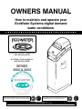
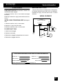
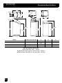
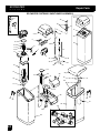
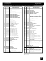
cut along dotted line to remove torn outer cover R SERIES 3000 & 3002 P/N: 7283586 OWNERS MANUAL How to maintain and operate your EcoWater Systems digital demand water conditioner R EcoWater Systems Conditioner with Remote (ECR) EcoWater Systems Refiner with Remote (ERR) SERIES 3000 & 3002 Systems Tested and Certified by NSF International and WQA against NSF/ANSI Standard 44 for softener performance and the reduction of barium and radium 226/228. ERR 3000R20 & ERR 3002R30 are Tested and Certified by NSF International and WQA against NSF/ ANSI Standard 42 for chlorine taste and odor. EcoWater Systems PO Box 64420, St. Paul MN 55164--0420 PRINTED IN USA Part No. 7283586 (Rev. D 11/27/06) ECOWATER S Y S T E M Unpacking, Table of Contents S UNPACKING TABLE OF CONTENTS EcoWater Systems conditioner models R70 and R50S are shipped from the factory in two cartons. These contain resin tank/controller assembly in one carton and the brine tank, cover, skin pack of small parts needed to assemble and install the unit, and this manual. EcoWater Systems conditioners, models R20, R30 and R40 are shipped from the factory in one master carton. The carton also includes a skin pack of small parts needed to assemble and install the unit, and this manual. Thoroughly check the EcoWater Systems conditioner for possible shipping damage and parts loss. Also inspect and note any damage to the shipping carton. Notify the transportation company if damage is present. EcoWater Systems is not responsible for in--transit damages. Remove and discard (RECYCLE) all packing materials. We suggest you keep the small parts on the skin--pack until you are ready to use them. Page Warranty Water Conditioning Planning Installation Installation 1st Time Programming Faceplate Controller Faceplate Controller Features / Options Remote Monitor Features / Options, FCC 3 4 5 6--8 9--10 11--15 user information Service Information Refilling with Salt Troubleshooting Dimensions / Specifications Repair Parts 16 17--21 17 19--21 22--23 24--27 SAFETY GUIDES Follow the installation instructions carefully. Failure to install the EcoWater Systems conditioner properly voids the warranty. Before you begin installation, read this entire manual. Then, obtain all the materials and tools you will need to make the installation. Check local plumbing and electrical codes. The installation must conform to them. Use only lead--free solder and flux for all sweat--solder connections, as required by state and federal codes. Use care when handling the EcoWater Systems conditioner. Do not turn upside down, drop, or set on sharp protrusions. Do not locate the EcoWater Systems conditioner where freezing temperatures occur. Do not attempt to treat water over 120°F. Freezing, or hot water damage voids the warranty. Avoid installing in direct sunlight. Excessive sun heat may cause distortion or other damage to non--metallic parts. The EcoWater Systems conditioner requires a minimum water flow of 3 gallons per minute at the inlet. Maximum allowable inlet water pressure is 125 psi. If daytime pressure is over 80 psi, nighttime pressure may exceed the maximum. Use a pressure reducing valve if necessary. (Adding a pressure reducing valve may reduce the flow.) The EcoWater Systems conditioner works on 24 volt--60 hz electrical power only. Be sure to use the included transformer and plug it into a nominal 120V, 60 cycle household outlet that is in a dry location only, grounded and properly protected by an over current device such as a circuit breaker or fuse. If transformer is replaced, use only the authorized service, Class II, 24 volt, 10 VA transformer. This device complies with Part 15 of the FCC Rules. Operation is subject to the following two conditions: (1) this device may not cause harmful interference, and (2) this device must accept any interference received, including interference that may cause undesired operation. Changes or modifications not expressly approved by the party responsible for compliance could void the user’s authority to operate the equipment. This system is not intended to be used for treating water that is microbiologically unsafe or of unknown quality without adequate disinfection before or after the system. If conditioner is being used to remove barium and / or radium 226 and 228, please verify performance by contacting 612--607--1700, ext. 6470 for testing treated water supply or check the water testing section of your local phone directory. European Directive 2002/96/EC requires all electrical and electronic equipment to be disposed of according to Waste Electrical and Electronic Equipment (WEEE) requirements. This directive or similar laws are in place nationally and can vary from region to region. Please refer to your state and local laws for proper disposal of this equipment. 2 ECOWATER S Y S T E M Warranty S LIMITED WARRANTY EcoWater Systems LLC Advantage Warranty Series ECR & ERR 3000 Water System Congratulations! You have just purchased the highest quality water conditioning product on the market. To register your warranty, complete the enclosed Warranty Registration Card and mail it within 30 days of purchase. To whom is this warranty extended? EcoWater Systems LLC warrants its products to the original owner and guarantees that the products will be free from defects in materials and workmanship from the original date of installation. How does my warranty work? If, during the respective warranty period, a part proves, after inspection by EcoWater, to be defective, EcoWater will, at its sole option repair or replace that part at no charge, other than normal shipping, installation or service charges. What is covered by the warranty? EcoWater Systems LLC guarantees that, for the LIFETIME of the original owner, the SALT TANK and the MINERAL TANK will not rust, corrode, leak, burst, or in any other manner fail to perform their proper functions and that, for a period of TEN YEARS, the VALVE BODY will be free of defects in materials and workmanship and will perform its proper function and that, for a period of FIVE YEARS, the ELECTRONIC FACEPLATE and ALL OTHER PARTS, including the REMOTE MONITOR will be free of defects in materials and workmanship and will perform their normal functions. Only on models designated as ERR on the rating decal, is the resin bed guaranteed, for the lifetime of the original owner, to be free of defects in materials and workmanship and to remove chlorine taste and odor from a municipal water supply. How do I obtain warranty service? Should you need service, your local, independent EcoWater Dealer is only a phone call away. PHONE: To obtain warranty service, notice must be given, within thirty (30) days of the discovery of the defect, to your local EcoWater Systems dealer. If I need a part replaced after the factory warranty expires, is the replacement part warranted? Yes, EcoWater Systems LLC warrants FACTORY REPAIRS as well as all REPLACEMENT PARTS for a period of 90 DAYS. This warranty does not include normal shipping, installation or service charges. Are any additional warranties available? We are pleased to say, YES! EcoWater Systems LLC sells an EXTENDED, PARTS ONLY WARRANTY for the ELECTRONICS portion of your product. This warranty is called the “Perfect Ten” and extends the five year warranty on the electronic FACEPLATE, WIRING HARNESS, DRIVE MOTOR, TRANSFORMER, POWER CORD, SENSOR HOUSING, and MICRO SWITCHES to a total of TEN YEARS from the date of original installation. Your local dealer will provide details regarding this warranty or will refer you to the factory for additional information. In addition, the 3000 SERIES product carries the CREST OF EXCELLENCE GUARANTEE that, should you experience a repetitive problem that remains uncorrected, EcoWater will, during the FIRST YEAR OF INSTALLATION, replace the product with the exact or comparable product.* This guarantee may be subject to normal shipping and installation or service charges. General Provisions The above warranties are effective provided the water conditioner is operated at water pressures not exceeding 125 psi, and at water temperatures not exceeding 120°F (and on a municipal chlorinated water supply -- models designated as ERR on the rating decal); provided further that the water conditioner is not subject to abuse, misuse, alteration, neglect, freezing, accident or negligence; and provided further that the water conditioner is not damaged as the result of any unusual force of nature such as, but not limited to, flood, hurricane, tornado or earthquake. EcoWater Systems LLC, is excused if failure to perform its warranty obligations is the result of strikes, government regulation, materials shortages, or other circumstances beyond its control. *THERE ARE NO WARRANTIES ON THE WATER CONDITIONER BEYOND THOSE SPECIFICALLY DESCRIBED ABOVE. ALL IMPLIED WARRANTIES, INCLUDING ANY IMPLIED WARRANTY OF MERCHANTABILITY OR OF FITNESS FOR A PARTICULAR PURPOSE, ARE DISCLAIMED TO THE EXTENT THEY MIGHT EXTEND BEYOND THE ABOVE PERIODS. THE SOLE OBLIGATION OF ECOWATER SYSTEMS LLC UNDER THESE WARRANTIES IS TO REPLACE OR REPAIR THE COMPONENT OR PART WHICH PROVES TO BE DEFECTIVE WITHIN THE SPECIFIED TIME PERIOD, AND ECOWATER IS NOT LIABLE FOR CONSEQUENTIAL OR INCIDENTAL DAMAGES. NO ECOWATER DEALER, AGENT, REPRESENTATIVE, OR OTHER PERSON IS AUTHORIZED TO EXTEND OR EXPAND THE WARRANTIES EXPRESSLY DESCRIBED ABOVE. Some states do not allow limitations on how long an implied warranty lasts or exclusions or limitations of incidental or consequential damage, so the limitations and exclusions in this warranty may not apply to you. This warranty gives you specific legal rights, and you may have other rights which vary from state to state. This warranty applies to consumer--owned installations only. GUARANTEE BOND The Safeco Insurance Company of America has issued it’s bond in the form shown below, guaranteeing full performance by EcoWater Systems LLC SAFECO INSURANCE COMPANY OF AMERICA, hereinafter called ‘‘Surety,’’ guarantees unto Bank of New York as Trustee holding said Guarantee Bond under the terms of a Trust Agreement dated April 9, 2003, for the use and benefit of original purchasers of residential EcoWater Systems Units within the Continental United States, as described herein, that EcoWater Systems LLC, will discharge the obligations of the ‘‘EcoWater Bonded Parts and Service Guarantee Policy.’’ PROVIDED, HOWEVER, that: 1 Liability of Surety hereunder shall not exceed the sum of FIVE HUNDRED AND 00/100th DOLLARS ($500.00) as to any one installation, and shall not exceed the sum of FIVE HUNDRED THOUSAND AND 00/100th DOLLARS ($500,000.00) in the aggregate, and 2 There shall be no liability hereunder as to any purchaser to whom there has not been issued at the time of installation and purchase completed registration card which is enclosed with a facsimile of this bond, and who has not returned such card in accordance with this guarantee. 3 Claim must be made by such original purchaser in writing within 30 days from the expiration of these guarantees upon EcoWater Systems LLC, PO Box 64420, St. Paul, MN 55164, to perform the terms of said guarantee, and notice of any default on such guarantee must be sent to Surety at its address by Registered Mail. SAFECO INSURANCE COMPANY OF AMERICA This is to certify that the original of the above guarantee and bond is on file with Bank of New York. BANK OF NEW YORK As Trustee 3 ECOWATER S Y S T E M S WATER CONDITIONING Water conditioning is the treatment of several conditions occuring in household water. The conditions treated by the unit you have purchased are: (1) Hardness, (2) Iron, (3) Sediments, (4) Barium and (5) Radium 226 and 228. These are described below: 1. HARDNESS is a term to describe the presence of calcium and magnesium minerals in water. A chemical analysis accurately measures the amount of minerals in grain weight. For example, one gallon of water with 5 grains per gallon (gpg) hardness has dissolved minerals, that if solidified, about equals the size of one ordinary aspirin tablet. One gallon of water, 25 gpg hard, has a mineral content equal in size to 5 aspirin tablets. Water hardness varies greatly across the country. It generally contains from 3 to 100 gpg. Hard water affects living in general. Hardness minerals combine with soap to make a soap curd. The curd greatly reduces the cleaning action of soap. Precipitated hardness minerals form a crust on cooking utensils, appliances, and plumbing fixtures. Even the tastes of foods are affected. A water softener removes the hardness minerals to eliminate these problems, and others. IMPORTANT: Water softeners using sodium chloride (NaCl) salt for regeneration add sodium to the water. Persons on sodium restricted diets should consider the added sodium as part of their overall intake. Water softeners using potassium chloride (KCl) salt for regeneration add potassium to the water. Persons on potassium restricted diets should consider the added potassium as part of their overall intake. 2. IRON in water is measured in parts per million (ppm). The total* ppm of iron, and type or types*, is determined by chemical analysis. Three different types of iron in water are: (a) Ferrous (clear water), (b) Ferric (red water), and (c) Bacterial and organically bound iron. *Water may contain one or more of the four types of iron and any combination of these. Total iron is the sum of the contents. 4 Water Conditioning a. Ferrous (clear water) iron is soluble and dissolves in water. It is usually detected by taking a sample of water in a clear bottle or glass. Immediately after taking, the sample is clear. As the water sample stands, it gradually clouds and turns slightly yellow or brown as air oxidizes the iron. This usually occurs in 15 to 30 minutes. An EcoWater Systems conditioner will remove moderate amounts of this type of iron (see specifications). b. Ferric (red water), and c. Bacterial and organically bound irons are insoluble. This iron is visible immediately when drawn from a faucet because it has oxidized before reaching the home. It appears as small cloudy yellow, orange, or reddish suspended particles. After the water stands for a period of time, the particles settle to the bottom of the container. Generally these irons are removed from water by filtration. Chlorination is also recommended for bacterial iron. An EcoWater Systems conditioner will remove minimal quantities (see specifications) of ferric iron. 3. SEDIMENT is fine, foreign material particles suspended in water. This material is most often clay or silt. Extreme amounts of sediment may give the water a cloudy appearance. A sediment filter normally corrects this condition. 4. BARIUM is a naturally occurring metal that makes its way into water through drilling wastes, smelting copper, and producing motor vehicle parts. The Environmental Protection Agency (EPA) has the authority to determine chemicals that cause health effects and at what levels. EPA created a list of harmful chemicals and their maximum contaminant levels (MCL), to set limits for public water supplies to maintain. Barium’s MCL is 2 parts per million (PPM). The level of barium in water can be determined through a chemical analysis. 5. RADIUM is a naturally occurring radioactive metal that can be found in most drinking water at low levels. Higher levels occur when ground water passes through bedrock containing high concentrations of radium. Radium 226 and 228 are also regulated by EPA with an MCL of 5 picocuries per liter (pCi/l). A chemical analysis is needed to measure the concentration of Radium 226 and 228. ECOWATER S Y S T E M Planning Installation S FIGURE 1 -- TYPICAL INSTALLATION DRAWINGS CONDITIONED WATER bypass valve 120V, 60Hz outlet HARD WATER HARD WATER 3-- valve bypass system outlet valve transformer (supplied) inlet valve to timer OUTLET to timer OUTLET INLET INLET bypass valve #7214383 valve drain hose brine tank overflow hose CABINET MODEL TWO TANK, MODEL brine tank overflow hose valve drain floor drain 1--1/2” airgap 1--1/2” airgap floor drain Tie or wire valve drain hose in place, to keep over floor drain. NOTE: Faceplate and support not shown for clarity of drawing. INLET - OUTLET PLUMBING OPTIONS S ALWAYS INSTALL either an EcoWater Systems bypass valve #7214383, or a 3 valve bypass system. Bypass valves allow you to turn off water to the softener for repairs if needed, but still have water in house pipes. drain hose FIGURE 2 -- DRAIN OPTIONS 1--1/2” airgap 1--1/2” airgap OTHER REQUIREMENTS S A drain is needed for regeneration discharge water. A floor drain is preferred, close to the EcoWater Systems conditioner. A laundry tub, standpipe, etc., are other drain options. drain hose STANDPIPE LAUNDRY TUB S A 120V--60Hz, grounded, continuously ‘‘live’’, electrical outlet is needed within 10’ of the EcoWater Systems conditioner. NOTE: Codes in the state of Massachusetts require installation by a licensed plumber. For installation, use plumbing code 248--CMR of the Commonwealth of Massachusetts. 5 ECOWATER S Y S T E M Installation S 1. INSTALL BYPASS VALVE and/or COPPER TUBES a. IF INSTALLING AN ECOWATER SYSTEMS BYPASS VALVE, put lubricated o--ring seals onto both bypass valve ports (FIGURE 3B). Carefully slide the bypass valve into the softener valve and install the “C” clips. b. Slide a lubricated o--ring seal onto each of the copper tubes. Carefully insert the copper tubes into the bypass valve (FIGURE 3B), or into the softener valve (FIGURE 3 and 3A). Then install the ‘‘C’’ clips. NOTE: For lubrication, use silicone grease approved for potable water supplies. 2. TURN OFF WATER SUPPLY a. Close the main water supply valve, near the well pump or water meter. b. Shut off the electric or fuel supply to the water heater. c. Open high and low faucets to drain all water from the house pipes. 3. INSTALLING THREE VALVE BYPASS If installing a 3--valve bypass system, plumb as needed using FIGURE 1 as a guide. When installing sweat copper, be sure to use lead--free solder and flux, required by federal and state codes. Use pipe joint compound on outside pipe threads. 4. ASSEMBLE INLET AND OUTLET PLUMBING Measure, cut, and loosely assemble pipe and fittings from the main water pipe (or from the bypass valves installed in step 3), to the inlet and outlet copper tubes, installed in step 1b. continued FIGURE 3 A. clip turbine support clip (2) copper tube (2) VALVE INLET o--ring (2) turbine support 6 copper tube B. Bypass Valve Installation o--ring copper tube (2) o--ring (2) ECOWATER S Y S T E M Installation S 5. CONNECT INLET AND OUTLET PLUMBING 6. COLD WATER PIPE GROUNDING a. SOLDERED COPPER The house cold water pipe (metal only) is often used as a ground for the house electrical system. The 3-valve bypass type of installation, shown in FIGURE 1, will maintain ground continuity. If you use the plastic bypass, continuity is broken. To restore the ground, do either step a or b following. (1) Thoroughly clean and flux all joints. (2) Pull the plastic ‘‘C’’ clips and remove the inlet and outlet tubes from the valve. Remove o--rings from the tubes. DO NOT solder with tubes in the valve. Soldering heat will damage the valve. NOTE: If installing a ground as shown in FIGURE 4A, place hose clamps on copper tubes before soldering (see step 6a). a. Use the included gound clamp kit to make a jumper across the inlet and outlet copper tubes, FIGURE 4A. (3) Make all solder connections. Be sure to keep fittings fully together, and pipes square and straight. b. Install a #4 copper wire across the removed section of main water pipe, securely clamping at both ends, FIGURE 4B (parts not included). b. THREADED PIPE 7. INSTALL VALVE DRAIN HOSE (1) Apply pipe joint compound to all outside pipe threads. NOTE: See valve drain options on page 5. (2) Tighten all threaded joints. (3) If soldering to the inlet and outlet tubes, observe step a above. c. CPVC PLASTIC PIPE (1) Clean, prime and cement all joints, following the manufacturer’s instructions supplied with the plastic pipe and fittings. (2) If soldering to the inlet and outlet tubes, observe step a above. A FIGURE 4 a. Connect a length of 1/2” I.D. hose (check codes) to the valve drain elbow, on the controller. Use a hose clamp to hold the hose in place. Route the hose out through the notch in the back of the top cover. b. Run the hose to the floor drain, and as typically shown in FIGURE 1, tie or wire the end to a brick or other heavy object. This will prevent ‘‘whipping’’ during regenerations. Be sure to provide a 1--1/2” minimum air gap, to prevent possible sewer water backup. continued FIGURE 6 FIGURE 5 3 -- Valve Bypass OUTLET VALVE nozzle & venturi ground clamp o--ring brine tubing nut--ferrule PULL OUT for service screen clamp (2) INLET VALVE EcoWater Systems Bypass Valve elbow B BYPASS VALVE ground wire Note: To ease brine tubing connection, use the elbow and o--ring seal as shown. Lubricate the o-ring and insert into the elbow. Turn the elbow on and tighten. Then, back--off up to one turn, as needed. PUSH IN for bypass from conditioner to conditioner D for SERVICE: - Open the inlet and outlet valves. - Close the bypass valve. D for BYPASS: - Close the inlet and outlet valves. - Open the bypass valve. 7 ECOWATER S Y S T E M 8. INSTALL BRINE TANK OVERFLOW HOSE a. Connect a length of 1/2” I. D. hose to the brine tank overflow elbow and secure in place with a hose clamp. b. Run the hose to the floor drain, or other suitable drain point no higher than the drain fitting on the tank. If the tank overfills with water, the excess water flows to the drain point. 9. On Two Tank models, connect the brine tubing to the nozzle and venturi housing. 10. ADD WATER AND SALT TO THE BRINE TANK a. Using a pail or garden hose, add about 3 gallons of water into the brine tank. DO NOT pour into the brinewell. b. Add salt to the brine tank. It is recommended to fill the brine tank no more than 1/2 full. You can use most water conditioner salts, but it must be clean. Recommended nugget, pellet or coarse solar salts have less than 1% impurities. Salt storage capacity is shown on page 22. NOTE: See page 17 for additional information on salt. 11. SANITIZING THE ECOWATER SYSTEMS CONDITIONER Care is taken at the factory to keep your EcoWater System conditioner clean and sanitary. Materials used to make the unit will not infect or contaminate your water supply, and will not cause bacteria to form or grow. However, during shipping, storage, installing and operating, bacteria could get into the unit. For this reason, sanitizing as follows is suggested ¡ when installing. 8 Installation S ...Remove the brinewell cover and pour about 1--1/2 oz. (2 to 3 tablespoons) of common household bleach into the softener brinewell. Clorox, Linco, BoPeep, White Sail, Eagle, etc. are brand names of bleach readily available. Replace the brinewell cover. ...The final step in the sanitizing procedure is done as you complete the following steps, including controller programming on page 9. ¡ Recommended by the Water Quality Association. On some water supplies, the EcoWater System Unit may need periodic disinfecting. 12. CONNECT TRANSFORMER a. Plug the transformer into a continuously ‘‘live’’, grounded, 120V--60Hz house electrical outlet, in a dry location and approved by local codes. THE UNIT WORKS ON 24V ONLY. DO NOT CONNECT WITHOUT THE TRANSFORMER. 13. START A RECHARGE Press the RECHARGE keypad, move cursor to Set Recharge Now and press SELECT/EXIT ( ↵ ) keypad, starting a recharge. This recharge draws the sanitizing bleach into and through the EcoWater Systems conditioner. Any air remaining in the unit is purged to the drain. COMPLETE THE PROGRAMMING STEPS ON PAGES 9 AND 10. ECOWATER S Y S T E M S SALT LEVEL keypad Programming the Digital Demand Faceplate Controller ↑ display keypad SELECT/EXIT keypad RECHARGE keypad ↓ keypad TANK LIGHT keypad THE FOLLOWING STEPS ARE FOR FIRST TIME SET UP ONLY. When the transformer is plugged in, a ‘‘beep’’ will sound, followed by the factory set model code display and software version for a few seconds. Then, 12:00 PM present time display. 3. SET WATER HARDNESS: The controller is 1. MODEL CODE: The controller is factory set to the model code, which provides the shortest recharge times and greatest water savings. Verify the correct model code or set if needed. Note: To reset the model code, see page 15. 2. SET THE CLOCK: Use the (↑) or (↓) keypads to set the present time of day, being sure AM or PM shows, as applicable. Press (↑) to move the display ahead; press (↓) to move the time backward. NOTE: Each press of a keypad changes the time by 1 minute. Holding a keypad in changes the time by 32 minutes each second. Pressing the SELECT/EXIT (↵ ) keypad will set the clock. factory set to 25 grains. Set the grains per gallon hardness of your water supply. Water hardness is determined by water analysis, or call your local water department. Use the (↑) keypad to advance the number; use the (↓) keypad to reduce the number. Each press of a keypad changes the display by 1. Hold down the keypad to scroll. After 25, scrolling will be at a faster rate. NOTE: To compensate for iron in the water, add 5 to the hardness number for each 1 ppm of iron. Pressing the SELECT/EXIT (↵) keypad will set the hardness level. NOTE: If using potassium chloride (KCl) instead of standard sodium chloride (NaCl) water softener salt, hardness setting must be increased by 25%. 9 ECOWATER S Y S T E M S Programming the Digital Demand Faceplate Controller 4. SET RECHARGE (REGENERATION) TIME: The controller is factory set to 2:00 AM. At this setting, the EcoWater Systems conditioner begins recharge, or regeneration, ending no later than 5:30 AM. This is a good time in most households because water is not being used. If hot water is used while the unit is regenerating, the water heater will refill with hard water. To select a different recharge start time, use the (↑) or (↓) keypad. Pressing the SELECT/ EXIT ( ↵ ) keypad will set the recharge time. GREEN LED AMBER LED RED LED 5. REMOTE SET-- UP: Press SELECT/EXIT ( ↵ ) to enter the Primary Menu. Move the cursor next to Advanced/Service Menu and press SELECT/EXIT ( ↵ ) to enter this Menu. Warning screen will show. Press (↑) keypad to continue. Move cursor to Test Remote and press SELECT/EXIT ( ↵ ) to enter this screen. The controller will start sending a signal to the remote every 3 seconds. Press reset on the back of remote. When the remote is receiving this signal, the LED’s will flash red, amber, green. Now remote can be placed in a convenient location. The remote may not work in all places in your home. If the red LED flashes twice every 3 seconds, the remote is out of range of signal and needs to be repositioned. Press SELECT/EXIT (↵ ) to exit to the Advanced/Service Menu. Move square cursor (J) to EXIT and press SELECT/EXIT (↵ ). Now the unit should start transmitting a normal signal. 6. Press the RECHARGE keypad to get to the recharge menu. Move the cursor to Start Recharge Now and press the SELECT/EXIT ( ↵ ), starting a recharge. This recharge draws the bleach (see step 11, page 8) through the EcoWater Systems conditioner to sanitize it and to purge any air remaining in the resin tank assembly. 7. RESTART THE WATER HEATER: Turn on the electric or fuel supply to the water heater, and light the pilot, if applies. NOTE: When the sanitizing regeneration is over, all remaining bleach is flushed from the conditioner and your cold water supply is ready for use. However, the water heater is filled with HARD water and, as hot water is used, it refills with conditioned water. In a few days, the hot water will be fully conditioned. To have fully conditioned hot water immediately, wait until the recharge (step 6) is over. Then, drain the water heater until water runs cold. INSTALLATION OF THE DIGITAL DEMAND ECOWATER CONDITIONER IS COMPLETE. Additional faceplate controller features and options are described on following pages. 10 ECOWATER S Y S T E M S Faceplate Controller, Features/Options FEATURES AND OPTIONS NORMAL SCREEN VIEWS The display will scroll through as many as 5 screens at an interval of 4 seconds each. F Soft Water Available will show a percent of available soft water and a bar graph at the bottom of the display. F Water Flow Rate shows gallons per minute (GPM) flowing through the system at that time and a moving bar graph at the bottom of the screen. F Recharge Tonight is shown only if the unit will be initiating a recharge that night. F Salt Level is Low is shown only if the salt level is below the amount set for warning. F If the unit is in recharge, the display will show remaining time in recharge and current stage of recharge. PROGRAM MEMORY: If electrical power to the EcoWater Systems conditioner goes off, the display is blank, but the faceplate controller keeps the correct time for at least two days. When electrical power comes on again, you have to verify clock time is correct. The MODEL CODE, HARDNESS and RECHARGE TIME never need resetting unless a change is desired. Even if the controller is incorrect, after a long power outage, the unit works as it should to keep your water conditioned. However, regenerations may occur at the wrong time of day until you reset the controller to the correct time of day. To reset present time, see step 2 on page 9. CONTROL FEATURES: There are three keypads on the left side of the display. Salt Level keypad is used when adding salt to the brine tank. The level number on the brinewell corresponds to the number to program into the controller. Recharge keypad has two options: Set/Cancel recharge tonight, which either sets or cancels a recharge for that night and Start Recharge Now, which will start a recharge immediately. NOTE: If in a recharge, and the Recharge keypad is pressed, it will advance the valve to the next regeneration cycle. On cabinet style units, there is also a Tank Light keypad. This will turn tank light on or off, and will work while in any screen. The tank light will automatically turn off after 4 minutes. D SOUND ‘‘BEEPER’’-- A ‘‘beeper’’ sounds while pressing keypads for controller setup. One beep signals a change in the faceplate display. Repeated beeps means the controller will not accept a change from the keypad you have pressed, telling you to use another keypad. For example, while setting the hardness number, the beeper sounds repeatedly when the display reaches 1 using the (↓) keypad or 160 using the (↑) keypad. SALT LEVEL: This feature is used when salt is added to the conditioner. Press the salt level keypad and use the (↑) keypad to reset the level of salt as it corresponds to the decal on the brinewell. Press the SELECT/ EXIT (↵ ) to set and return to Normal Screen Views. 11 ECOWATER S Y S T E M S Faceplate Controller, Features/Options INITIATING EXTRA RECHARGES RECHARGE NOW: Press the Recharge keypad to go to the recharge menu. Move square cursor down to Start Recharge Now. Press SELECT/EXIT keypad and a recharge begins immediately. To assure an adequate supply of conditioned water, at times of unusual or unexpected high water use demand, use the RECHARGE NOW feature. For example, if you have guests and the Soft Water Available screen is at or below 50%, you could deplete conditioned water capacity before the next recharge is automatically initiated. To be sure this will not happen, use RECHARGE NOW to restore 100% conditioned water capacity. RECHARGE TONIGHT: Press the Recharge keypad to go to the recharge menu. Move cursor down to Set/ Cancel Recharge Tonight. Press SELECT/EXIT keypad to return to Normal Screen Views. When this feature is set, the EcoWater Systems conditioner will regenerate at the next programmed start time. This feature is beneficial to assure a sufficient supply of conditioned water for expected heavy water usage the next day. To cancel a recharge when RECHARGE TONIGHT is shown, press the Recharge keypad to go to the recharge menu. Move cursor down to Set/Cancel Recharge Tonight. Press SELECT/EXIT keypad to return to Normal Screen Views. PRIMARY MENU The following is a description of the options in the Primary Menu. To enter this menu press SELECT/EXIT ( ↵ ) keypad and move square cursor (J) to menu choice. To exit to Normal Screen Views move square cursor (J) to EXIT, which appears at either the top or the bottom of this menu. If no keypad has been pressed display will show for 4 minutes before returning back to the Normal Screen Views. Set Clock: Enter Primary Menu. Press the (↑) or (↓) keypads until cursor is next to Set Clock. Again, use the (↑) or (↓) keypads to set the present time of day, being sure AM or PM shows, as applicable. Press (↑) to move the display ahead; press (↓) to move the time backward. NOTE: Each press of a keypad changes the time by 1 minute. Holding a keypad in changes the time by 32 minutes each second. Press the SELECT/EXIT ( ↵ ) keypad to set. Set Water Hardness: Enter Primary Menu. Press the (↑) or (↓) keypads until cursor is next to Set Hardness. Press the SELECT/EXIT ( ↵ ) keypad once to display a flashing number and GRAINS. Set the grains per gallon hardness of your water supply. Use the (↑) keypad to advance the number; use the (↓) keypad to reduce the number. Pressing the SELECT/EXIT (↵) keypad will set the hardness level. NOTE: If using potassium chloride (KCl) instead of standard sodium chloride (NaCl) water softener salt, hardness setting must be increased by 25%. Set Recharge (Regeneration) Time: Enter Primary Menu. Press the (↑) or (↓) keypads until cursor is next to Set Recharge Time. Press the SELECT/EXIT ( ↵ ) keypad once to display a flashing 2:00 AM. At this setting, the EcoWater Systems conditioner begins recharge, or regeneration, at 2:00 AM., ending no later than 5:30 AM. This is a good time in most households because water is not being used. If hot water is used while the unit is regenerating, the water heater will refill with hard water. To select a different recharge start time, use the (↑) or (↓) keypad. Pressing the SELECT/ EXIT (↵) keypad will set the recharge time. continued 12 ECOWATER S Y S T E M S Faceplate Controller, Features/Options Primary Menu, continued Water Flow Rate: Enter Primary Menu. Press the (↑) or (↓) keypads until cursor is next to Water Flow Rate. Press the SELECT/EXIT (↵ ) keypad. When selected, this screen will show the water flow rate in gallons per minute (GPM) or liters per minute (LPM) with the moving bar graph at the bottom of the display. Water Used Today: Enter Primary Menu. Press the (↑) or (↓) keypads until cursor is next to Water Used Today. Press the SELECT/EXIT ( ↵ ) keypad and the gallons/liters used since midnight will be shown in the display. Average Water Use: Enter Primary Menu. Press the (↑) or (↓) keypads until cursor is next to Average Water Use. Press the SELECT/EXIT ( ↵ ) keypad and the average gallons/liters use each day will be shown in the display. Soft Water Meter: Enter Primary Menu. Press the (↑) or (↓) keypads until cursor is next to Soft Water Meter. Press the SELECT/EXIT (↵) keypad. This screen is similar to a trip odometer in that it will count the number of gallons/liters through the system until it is reset. To reset back to zero press the (↓) keypad. Set Rolling Screen: Enter Primary Menu. Press the (↑) or (↓) keypads until cursor is next to Set Rolling Screen. Press the SELECT/EXIT (↵) keypad. This menu will disable the Normal Screen Views from scrolling and will show only the screen that is most current. Set 12/24 Hour Clock: Enter Primary Menu. Press the (↑) or (↓) keypads until cursor is next to Set 12/24 Hour Clock. Press the SELECT/EXIT (↵ ) keypad. Moving the (↑) or (↓) keypads will change clock display from 12 hour (AM & PM) or 24 hour format. Set Gallons/Liters: Enter Primary Menu. Press the (↑) or (↓) keypads until cursor is next to Set Gallons/Liters. Press the SELECT/EXIT (↵) keypad. Moving the (↑) or (↓) keypads will change displays to indicate water in gallons or liters. Set Grains/PPM: Enter Primary Menu. Press the (↑) or (↓) keypads until cursor is next to Set Grains/PPM. Press the SELECT/EXIT (↵) keypad. Change between diplaying hardness units in grains or parts per million (PPM). continued 13 ECOWATER S Y S T E M S Faceplate Controller, Features/Options Primary Menu, continued Remote Status: Enter Primary Menu. Press the (↑) or (↓) keypads until cursor is next to Remote Status. Press the SELECT/EXIT ( ↵ ) keypad. The current remote status is displayed. Send E.A.S.E. Message: Enter Primary Menu. Press the (↑) or (↓) keypads until cursor is next to Send E.A.S.E. Message. Press the SELECT/EXIT (↵) keypad. The unit will automatically start sending E.A.S.E. message and show a progress bar on the display. See page 18. Advanced/Service: By entering these menus, a warning screen will first be displayed. Only technicians or knowledgeable users should use these menus. ADVANCED / SERVICE MENU The following is a description of the options in the Advanced/Service Menu. To enter any of the following menus, press SELECT/EXIT (↵) to enter Primary Menu. Press the (↑) or (↓) keypads until cursor is next to Advanced/Service. Press the SELECT/EXIT ( ↵ ) keypad to enter this menu. Warning screen will show, press the (↑) keypad to continue. To exit to Normal Screen Views move square cursor (J) to EXIT, which appears at either the top or the bottom of this menu. If no keypad has been pressed display will show for 4 minutes before returning back to the Normal Screen Views. Set Language: Press the (↑) or (↓) keypads until cursor is next to Set Language. Language can be changed from English to Spanish or French. Test Remote: Press the (↑) or (↓) keypads until cursor is next to Test Remote and press SELECT/EXIT ( ↵ ). At set up, the unit will send a signal to the remote every 3 seconds to allow for correct positioning of remote monitor. Press SELECT/EXIT ( ↵ ) to exit. See page 16 for information on the Remote Monitor. Set Low Salt Alert: Press the (↑) or (↓) keypads until cursor is next to Set Low Salt Alert and press SELECT/EXIT ( ↵ ). Use the (↑) or (↓) keypads to change Alert Level. At this level the controller will signal that salt needs to be added to the conditioner brine tank. Press SELECT/EXIT (↵) to exit. NOTE: This warning will indicate the softener’s inability to reduce barium & radium 226/228 effectively. Changing the Low Salt Alert to less than 2 will void the proper function of this indicator. Efficiency Mode: Press the (↑) or (↓) keypads until cursor is next to Efficiency Mode and press SELECT/EXIT ( ↵ ). Default is Auto Adjusting which has a minimum efficiency of 3350 grains/lb of salt. Use the (↑) or (↓) keypads to change to either High Capacity which sets the regeneration salt doses that are increased by a certain % to handle applications requiring 1.5 PPM (parts per million) or less soft water, or to handle special cases such as low leakage requirement or problem water conditions; and Salt Efficient which operates at a minimum of 4000 grains/lb of salt. Changing this setting will prompt a warning that changes could affect performance. Press SELECT/EXIT (↵ ) to exit. NOTE: California regulations require the Efficiency Mode to be ON for sale in California. continued 14 ECOWATER S Y S T E M Faceplate Controller, Features/Options S Advanced/Service Menu, continued Set Model: The controller is factory set to the model code, which provides the shortest recharge times and greatest water savings. For operation at higher salt efficiency levels, the alternate model code selection is required (see the product specification sheet). Do the following to change to this code, if desired. 1) Press the (↑) or (↓) keypads until cursor is next to Set Model and press SELECT/EXIT ( ↵ ). Warning screen will display, press (↑) to continue. 2) Use the (↑) or (↓) keypads to change to new model code. Be sure to set the correct code, or the EcoWater conditioner will operate on incorrect timing. NOTE: If this feature is changed, it will delete all information stored in the controller (Hardness, Recharge time will have to be reset. All usage history will be cleared). When you are certain the correct code appears, press SELECT/EXIT (↵) to exit. Warning screen will appear after changing model code, press (↑) to continue. The display will return to the start--up screens. MODEL NUMBER (on rating decal) Required Code Alternate Code ECR 3000R20 R20 E20 ERR 3000R20 R20+ E20+ ECR 3000R30 R30 E30 ECR 3002R30 2R30 2E30 ERR 3002R30 2R30 2E30 ECR 3002R40 2R40 2E40 ECR 3002R50S 2H50 -- ECR 3002R70 2R70 2E70 Restore To Factory Settings: Press the (↑) or (↓) keypads until cursor is next to Restore System and press SELECT/EXIT ( ↵ ). Default is No. If set to Yes will restore controller to factory settings. NOTE: This will affect ALL settings, and controller will go through first time set--up screens again. Press SELECT/EXIT (↵ ) to exit. 15 ECOWATER S Y S T E M S Remote Monitor, Features/Options This EcoWater Systems conditioner comes with a Remote Monitor which can conveniently be placed in your home for viewing of your conditioners’ status. During normal operation, the green LED will flash at intervals of 5 seconds. If the unit requires salt, the amber LED will flash, and if the unit needs to be checked the red LED will flash. GREEN LED AMBER LED RED LED The controller on the EcoWater Systems conditioner will send a signal to the remote monitor every minute. The remote monitor will listen for a signal every 10 minutes. Any changes in softener status could possibly take up to 10 minutes before the remote registers the change. If the unit stops sending a signal, the remote will keep trying to listen for the signal. If after 10 minutes with no signal received, the remote will try 1 minute later and 2 minutes later to find the signal, gradually increasing the time between, but will keep trying to listen for the signal for up to two days. After 20 minutes with no signal received, the remote monitor will turn off the LED’s to conserve battery life, but will still be active. After two days with no signal received, the remote monitor will shut down untill the reset button is pushed (on back of remote). The EcoWater Systems remote uses 3 “AAA” batteries, which are included. To check batteries, press reset button on back of remote monitor. If batteries are good, the LED’s on the remote should scroll green, amber, red. If LED’s do not light, batteries need to be changed. If there is another EcoWater Systems conditioner within range of the remote, it may cause a conflict with the channel that the remote monitor is receiving. If the remote monitor displays the wrong message (example: low salt when salt is above warning level) this is an indication that the remote monitor is receiving a different signal. Follow the steps below to change the remote channel. Set Remote Channel: Enter Advanced/Service Menu. Move cursor next to Set Remote Channel and press SELECT/EXIT ( ↵ ). Default is random from 1 to 16. Press ( ↑ ) or ( ↓ ) to select new channel. Press SELECT/EXIT (↵ ) to exit to the Primary Menu and press reset button on back of remote monitor. NOTE: This device complies with Part 15 of the FCC Rules. Operation is subject to the following two conditions: (1) this device may not cause harmful interference, and (2) this device must accept any interference received, including interference that may cause undesired operation. Changes or modifications not expressly approved by the party responsible for compliance could void the user’s authority to operate the equipment. Note: ALSO SEE SERVICE INFORMATION, PAGES 17 THROUGH 21. 16 ECOWATER S Y S T E M Service Information S REFILLING WITH SALT CLEANING THE NOZZLE AND VENTURI Remove the brine tank cover and check the salt storage level frequently. If the conditioner uses all the salt before you add more, you will get hard water. Be sure the brinewell cover is on when adding salt. NOTE: In humid areas, it is best to keep the salt storage level lower, and to refill more often. RECOMMENDED SALT: Cube, pellet, coarse solar, etc., water conditioner salt is recommended. This type of salt is from high purity evaporated crystals, sometimes formed, or compressed, into briquets. It has less than 1% insoluble (will not dissolve in water) impurities. Clean, high grade rock salts are acceptable, but may require frequent brine tank cleaning to remove the ‘‘sludge’’ residue (insolubles) that collects at the bottom of the tank. SALT NOT RECOMMENDED: Rock salt, high in impurities, block, granulated, table, ice melting, ice cream making salts, etc., are not recommended. SALT WITH IRON REMOVING ADDITIVES: Some salts have an additive to help a water conditioner handle iron in a water supply. Although this additive may help keep the resin bed clean, it may also release corrosive fumes that will weaken and shorten the life of some EcoWater Systems conditioner parts. A clean nozzle and venturi (FIGURE 7) is a must for the EcoWater Systems conditioner to work right. This small unit creates the suction to move brine from the brine tank, into the resin tank. If it should become plugged with sand, silt, dirt, etc., the EcoWater Systems conditioner will not work, and you will get hard water. BREAKING A SALT BRIDGE Sometimes, a hard crust or salt bridge forms in the brine tank. It is usually caused by high humidity or the wrong kind of salt. When the salt bridges, an empty space forms between the water and the salt. Then, salt will not dissolve in the water to make brine. Without brine, the resin bed is not regenerated and you will have hard water. If the brine tank is full of salt, it is hard to tell if you have a salt bridge. Salt is loose on top, but the bridge is under it. Take a broom handle, or like tool, and push it straight down into the salt. If a hard object is felt, it’s most likely a salt bridge. Carefully push into the bridge in several places to break it. RESIN BED CLEANING If the water supply contains ‘‘clear water ’’ iron (see page NO TAG), regular resin bed cleaning is needed to keep the bed from coating with iron. Use resin bed cleaner, available from EcoWater Systems, following directions on the container. Clean the resin every 6 months, or more often if iron appears in your conditioned water supply. To get to the nozzle and venturi, remove the conditioner top cover. Be sure the conditioner is in the service cycle (no water pressure at nozzle and venturi). Then, holding the nozzle and venturi housing with one hand, turn off the cap. Do not lose the o--ring seal. Lift out the screen support and screen. Then, remove the nozzle and venturi. Wash the parts in warm, soapy water and rinse in fresh water. If needed, use a small brush to remove iron or dirt. Be careful not to scratch, misshape, etc., surfaces of the nozzle and venturi. Also, check and clean the gasket and flow plug(s) if dirty. Carefully replace all parts in the correct order. Lubricate the o--ring seal with silicone grease and locate in position. Install and tighten the cap, by hand only. Do not overtighten and break the cap or housing. FIGURE 7 cap install with numbered side UP, concave side down flow plug (not used on all models) o--ring screen support screen nozzle & venturi gasket flow plug (fill) nozzle & venturi housing cone screen 17 ECOWATER S Y S T E M Service Information S CAUTION: ALWAYS relieve water pressure in the EcoWater Systems conditioner, as follows, before removing parts from the valve or resin tank. DE--PRESSURIZE EcoWater Systems Bypass Valve PULL OUT for service 1. Put bypass valve(s) in bypass position. 2. Do Manual Advance step 1, page 20, (fill water to brine tank will depressurize the resin tank). PRESSURIZE 1. Put bypass valve(s) in service position. 2. Do Manual Advance steps 2 -- 5, page 20, to return unit to service. PUSH IN for bypass ALTERNATE METHOD 3--VALVE BYPASS DE--PRESSURIZE 1. Close the INLET valve. 2. Open HOT and COLD conditioned water house faucets. 3. Close the OUTLET valve and open the BYPASS valve. 4. Close all house faucets. PRESSURIZE 1. Open HOT and COLD house faucets. 2. Close the BYPASS valve and open the OUTLET valve. 3. Slowly, open the INLET valve. 4. Close all house faucets ECOWATER SYSTEMS BYPASS VALVE 3 -- Valve Bypass DE--PRESSURIZE water 1. Close the house main water supply valve. flow 2. Open HOT and COLD conditioned water faucets. BYPASS INLET VALVE VALVE 3. Push the bypass valve handle to bypass OUTLET VALVE position. Note: For hard water bypass to house faucets, reopen the main water supply valve. PRESSURIZE 1. Open HOT and COLD house faucets (main water supply valve open). 2. Pull the bypass valve handle to service position. 3. Close all house faucets. from conditioner to conditioner D for SERVICE: - Open the inlet and outlet valves. - Close the bypass valve. D for BYPASS: - Close the inlet and outlet valves. - Open the bypass valve. ECOWATER CONDITIONER OPERATION, ELECTRONIC CHECKOUT ALWAYS MAKE THE INITIAL CHECKS FIRST INITIAL CHECKS: 1. Does the time display show the correct time of day? ...If display is blank, check power source to the EcoWater Systems conditioner. ...If time is incorrect, power was off for over 2 days. The conditioner resumes normal operation, when power returns, but regenerations occur at the wrong time. ...If an error code shows in the display (example: Error 3), go to AUTOMATIC ELECTRONIC DIAGNOSTICS, page 19. 2. Are plumbing bypass valve(s) in service position (all the way open or closed, as applies). 3. Are the inlet and outlet pipes connected to the EcoWater Systems conditioner inlet and outlet respectively. 4. Is the transformer plugged into a ‘‘live’’, grounded wall outlet? 5. The valve drain hose must be free of kinks and sharp bends, and not elevated over 8’ above the floor. 6. Is there salt in the brine tank? 7. Is the brine tubing connected? See FIGURE 5, page 7. 8. Press SELECT/EXIT ( ↵ ) to enter Primary Menu. Move the cursor so that it is next to Set Hardness. Press the SELECT/EXIT ( ↵ ) keypad once to display the hardness setting. Be sure it is the correct setting for the household’s water supply. ---- Make a hardness test of the raw water and compare with the hardness setting. Also test a conditioned water sample to verify if a problem exists. ----Press SELECT/EXIT ( ↵ ) keypad to exit to Normal View Screens. If you do not find a problem after making the initial checks, do MANUAL INITIATED ELECTRONIC DIAGNOSTICS, and the MANUAL ADVANCE REGENERATION CHECK, pages 19 and 20. E.A.S.E.: EcoWater Systems digital demand controllers have the latest diagnostic technology. With E.A.S.E., or Electronic Automated Service Evaluation, a service person or homeowner can transmit operational data through the telephone, to a personal computer (PC). The PC processes the data to determine if all electrical functions are working normally, or helps to identify a problem should one occur. Ask your participating EcoWater Systems dealer for more information on this feature. 18 ECOWATER S Y S T E M Service Information S AUTOMATIC ELECTRONIC DIAGNOSTICS The faceplate computer has a self--diagnostic function for the electrical system (except input power and water meter). The computer monitors electronic components and circuits for correct operation. If a malfunction occurs, the computer attempts to self correct, displaying ADJUST VALVE in the Normal View Screen. If self correction fails, an error code appears in the faceplate display. The chart below shows the error codes that could appear, and the possible defects for each code. While an error code appears in the display, all faceplate keypads are inoperable except the SELECT keypad. SELECT remains operational so the service person can make the MANUAL INITIATED ELECTRONIC DIAGNOSTICS, below, to further isolate the defect, to check the water meter and to send an E.A.S.E. transmission. POSSIBLE DEFECT CODE Error 1 Error 2 Error 3 Error 4 Error 5 MOST LIKELY ' . . . . . . . . . . . . . . . . . . . . . . . . . . . . . . . . . . . . . . . . ' LEAST LIKELY wiring harness or connection to position switch / switch / valve defect causing high torque / motor inoperative faceplate PROCEDURE FOR REMOVING ERROR CODE FROM FACEPLATE: 1. Unplug transformer-------- 2. Correct defect-------3. Plug in transformer-------- 4. Wait for 8 minutes. The error code will return if the defect was not corrected. TROUBLESHOOTING, --open a nearby CONDITIONED WATER faucet-- MANUAL INITIATED ELECTRONIC DIAGNOSTICS 000 to 151 (continual) = repeats display for each gallon of water passing through the meter. Gallons up by one. To enter diagnostics, press the SELECT/EXIT (↵ ) to enter the menu. This screen contains information that can be used to troubleshoot errors. Use the (↑) and (↓) keypads to scroll through all lines on this screen. The first line shows time of day and error code. If you don’t get a reading in the display, with a faucet open, pull the sensor housing from the valve outlet port. Pass a small magnet back and forth in front of the sensor. You should get a reading. If you do get a reading, disconnect the outlet plumbing and check the turbine for binding. If you don’t get a reading, the sensor is probably defective. Second line is Pos: which shows what position the valve is in. Example: Service, Fill, Brining and Brine Rinse, Backwash and Fast Rinse. The clock to the right counts backward the time for each of the positions to be completed. BACK OF CONTROLLER CIRCUIT BOARD magnet sensor housing The next line is Req Pos: which is for requested position, or what position the valve is travelling to. Next line displays Motor:, either on or off, and Sw: (switch) either open or closed. Next is Trbn: (turbine) and Gals: (gallons) which indicate water meter operation as follows. 000 (steady) = conditioned water not in use...no flow through the meter. sensor pickup turbine support turbine continued 19 ECOWATER S Y S T E M S continued from page 19 Use the recharge keypad to manually advance the valve into each cycle and check correct switch operation, and observe the valve position indicator. Service Information (↵) to start a recharge. As the EcoWater Systems conditioner enters the fill cycle of regeneration, remove the brinewell cover and, using a flashlight, observe fill water entering the tank. NOTE: The position switch is closed when the plunger is depressed, open when extended. a. If water does not enter the tank, look for an obstructed nozzle and venturi, fill flow plug or brine tubing FIGURE 7, page 17. While in this diagnostic screen, the following information is available and may be beneficial. This information is retained by the computer from the first time electrical power is applied to the faceplate. 2. After verifying fill, press Recharge keypad to move the valve into brining*. A slow flow of water to the drain will begin. Verify brine draw from the brine tank by shining the flashlight into the brinewell and observing a noticeable drop in the liquid level. ...Remote: either Installed or Not Installed. ...Days: displays the number of days this faceplate has had electrical power applied. *If the 2ND BACKWASH option is set, the valve will enter backwash and fast rinse before brining...see page NO TAG. ...Rchg: to show the number of regenerations initiated by this faceplate since power was first applied. NOTE: Be sure water is in contact with the salt, and not separated by a salt bridge...see page 17. NOTE: This number resets to 0 if the model code is changed. a. If the unit does not draw brine, check for... ...dirty or defective nozzle and venturi, page 17 ...nozzle and venturi not seated on the gasket, or gasket defective ...restriction in valve drain, causing a back-pressure (bends, kinks, elevated too high, etc.), installation step 7, page 7 ...obstruction in brine valve or brine tubing, page NO TAG and FIGURE 5, page 7 ...inner valve failure (obstructed outlet disc, wave washer defective, etc.) ...Last Rchg: displays the number of days since last recharge. ...Cap: displays numerically the capacity the softener is operating at with 1 lowest and 5 highest. Press the SELECT/EXIT (↵ ) to exit to the Advanced/Service menu, move cursor up to EXIT and press SELECT/EXIT (↵ ) to go to Normal Screen Views. TROUBLESHOOTING, MANUAL ADVANCE REGENERATION CHECK This check verifies proper operation of the gearmotor, brine tank fill, brine draw, regeneration flow rates, and other controller functions. Always make the initial checks, and the manual initiated diagnostics first. 1. Press the RECHARGE keypad. Move cursor down to Start Rchg Now and press SELECT/EXIT 3. Again press Recharge keypad to move the valve into backwash. Look for a fast flow of water from the drain hose. a. If flow is slow, check for a plugged top distributor, backwash flow plug or drain hose. 4. Press Recharge keypad to move the valve to fast rinse position. Again look for a fast drain flow. Allow the unit to rinse for several minutes to flush out any brine that may remain from the brining cycle test. 5. To return the valve to service position, press ReCHARGE ONCE AGAIN. continued 20 ECOWATER S Y S T E M Service Information S OTHER SERVICE WATER HAS SALTY TASTE HARD WATER BYPASS (hard water ‘‘bleeds’’ into conditioned water supply). 1. Defective inlet disc, seal, or wave washer (see pages 26 and 27). 1. House water pressure low (adjust pump, if well system). 2. Partially restricted valve drain hose, top distributor, backwash flow plug, resin tank internal riser, or bottom distributor. WIRING SCHEMATIC 2. Missing or defective o--ring(s) at resin tank to valve connection. PWA on back of controller WATER LEAKS FROM DRAIN HOSE (during service). 24 VAC 6 pin connector 1. Defective inlet disc, seal, or wave washer. 2. Defective o--ring on inlet disc shaft. 24VAC 3. Defective outlet disc, seal, or wave washer. GND +5 OUT FLOODED SALT TANK 110 V 60 Hz TURBINE SENSOR 1. Nozzle venturi plugged. 2. Defective valve seals. 3. Restricted or plugged backwash/fast rinse controls. TRANSFORMER NC TANK LIGHT white POSITION SWITCH 4. Restricted or plugged drain line. M 24V NO FOR FUTURE REFERENCE, ENTER THE FOLLOWING INFORMATION MODEL NO. SERIAL NO. DATE CODE INSTALLATION DATE WATER HARDNESS GPG WATER HARDNESS SETTING on rating decal IRON CONTENT PPM (see page 15) on shipping carton 21 ECOWATER S Y S T E M Dimensions/Specifications S 20” 3--13/16” 14” IN 16” 14” OUT 14” 16” IN -- OUT IN -- OUT C 36--9/16” 45--1/8” A B 32--1/2” 32” MODEL NOMINAL RESIN TANK SIZE A B C ECR 3000R20 8” DIA. X 35” 39.5” -- -- ECR 3000R30, ECR 3002R30, ERR 3000R20 10” DIA. X 35” 39.5” 39.5” 44.8” ECR 3002R40, ERR 3002R30 10” DIA. X 47” -- 51.3” 56.6” ECR 3002R50S, ECR 3002R70 12” DIA. X 54” -- 57.1” 62.2” SALT STORAGE CAPACITIES H Two Tank Brine Tank -- 300 lbs H Cabinet Brine Tank (with 8 x 35 resin tank) -- 225 lbs H Cabinet Brine Tank (with 10 x 35 resin tank) -- 200 lbs 22 ECOWATER S Y S T E M Dimensions/Specifications S ECR 3000R20 ERR 3000R20 ECR 3000R30 ECR 3002R30 ERR 3002R30 ECR 3002R40 ECR 3002R50S ECR 3002R70 5,700 @ 1.1 16,800 @ 4.3 20,400 @ 7.5 6,700 @ 1.4 19,300 @ 5.2 23,600 @ 8.9 8,300 @ 1.6 25,000 @ 6.4 30,200 @ 11.3 8,100 @ 1.7 23,800 @ 6.4 29,200 @ 11.0 11,300 @ 2.2 33,200 @ 8.5 40,100 @ 14.8 23,000 @ 4.5 40,800 @ 9.9 47,900 @ 15.3 32,900 @ 6.2 57,600 @ 12.8 71,500 @ 19.3 5150 4790 5160 4790 5150 5110 5310 Service Flow Rate (gpm) 9.0 9.0 11.0 10.0 12.0 20.0 12.0 Pressure Drop at Service Flow Rate (psi) 10 6 8 8 13 15 11 Intermittent Flow Rate (gpm) @ 15 psi D 12.0 17.1 16.5 15.8 13.6 20.0 17.0 Intermittent Flow Rate (gpm) @ 30 psi D 19.4 26.8 25.8 25.2 21.6 30.0 22.0 Amount of High Capaciy Resin (cu ft) Rated Softening Capacity (Grains@ lbs Salt Dose) Rated Efficiency (gr/lb of Salt at Minimum Salt Dose) Y 0.60 0.71 0.89 0.88 1.18 1.53 2.05 Water Supply Max. Hardness (gpg) 40 50 60 60 75 95 125 Water Supply Max. Clear Water Iron (ppm) H 10 10 12 12 15 15 15 3.0 5.4 5.4 Min.-- Max. Working Pressure (psi) z 20 -- 125 Min.-- Max. Operating Temperature (_F) 40 -- 120 3 Min. Water Supply Flow Rate (gpm) Max. Flow Rate (gpm) to Drain During Regeneration Cycle 2.4 3.0 3.0 3.0 Y Efficiency ratings are only valid at the lowest salt dosage and service flow rate. rated according to NSF/ANSI standard 44. These softeners were efficiency D Intermittent flow rate does not represent the maximum service flow rate used for determining the softeners rated capacity and efficiency. Continuous operation at flow rates greater than the service flow rate may affect capacity and efficiency performance. The validity of these flow rates is verified by NSF. Capacity to remove clear water iron is substantiated by WQA test data. State of Wisconsin requires additional treatment if water supply contains greater than 5 ppm clear water iron. H z Canada working pressure limits: 1.4--7.0 kg/cm2 These softeners conform to NSF/ANSI 44 for the specific capacity claims as verified and substantiated by test data. ERR 3000R20 and ERR 3002R30 also conform to NSF/ANSI 42 for specific performance claims verified and substantiated by test data from Water Quality Association (WQA). 23 ECOWATER S Y S T E M Repair Parts S ECOWATER SYSTEMS CONDITIONER ASSEMBLY 43 1 42 40 41 2 14 3 39 44 9 10 11 4 5 8 12 45 38 31 7 13 6 37 32 36 14 33 35 34 19 15 29 28 20 18 21 18 16 19 20 17 27 26 23 22 22 30 46 25 24 24 23 21 ECOWATER S Y S T E M Repair Parts S ECOWATER SYSTEMS CONDITIONER ASSEMBLY KEY NO. PART NUMBER 1 7275907 2 KEY NO. PART NUMBER Transformer, 24V ---10VA 26 7274210 Rim (Cabinet) 7288489 Remote Indicator (batteries not included) 27 7214244 Vapor Barrier 3 7218662 Top Cover (Cabinet) 28 7273997 Salt Hole Cover 4 7210410 Faceplate (order one of following decals) 29 7274008 Brine Tank Cover (Two Tank) --- 7274359 Faceplate Decal (Cabinet) 30 7218612 Brine Tank (Two Tank) --- 7274553 Faceplate Decal (Cabinet Refiner) 31 7113008 Float, Stem and Guide Assembly --- 7274367 Faceplate Decal (Two Tank) --- 7221754 Float, Stem & Guide Asm, Model ECR 3002R50S, ECR 3002R70 --- 7274561 Faceplate Decal (Two Tank Refiner) 32 7170288 O ---ring, 15/16” x 1---3/16” 5 7285790 Rep’l PWA 33 1205500 Clip 6 7211173 Faceplate Support 34 7092252 Brine Valve Body 7 7088033 Clamp Retainer, 2 req. 35 7080653 Clip 8 7176292 Clamp Section, 2 req. 36 7131365 Screen 9 7170296 O ---ring Seal, 2---7/8” x 3---1/4” 37 7113016 Tubing Assembly, BV 10 7170254 O ---ring, 13/16” x 1---1/16” 38 7095470 Brine Tube 11 7077870 Top Distributor --- 7221746 12 7170270 O ---ring, 2---3/4” x 3” Brine Tube, Model ECR 3002R50S, ECR 3002R70 13 7105047 Repl. Distributor (bottom) 39 7171349 Screen 14 7114787 Resin Tank, 8” dia. x 35” 40 9003201 Nut---Ferrule, 2 req. --- 7113066 Resin Tank, 10” dia. x 35” 41 7094987 Union Connector 7161807 Tubing, 20 ft. PART DESCRIPTION PART DESCRIPTION --- 7092202 Resin Tank, 10” dia. x 47” 42 --- 7113074 Resin Tank, 12” dia. x 54” --- 7161768 Tubing, 100 ft. 15 0502272 Resin, 1 cu ft (stand. mesh) 43 7218670 Top Cover (Two Tank) --- 7052202 Resin, 1 cu ft (fine mesh) 44 7274286 Rim (Two Tank) 7218638 Tank Sleeve, Model ECR 3002R30 --- 0501741 Resin, 1/2 cu ft (stand. mesh) 45 --- 7175149 Shell Carbon (Refiner Models) --- 7218646 16 7124415 Gravel, 17 lbs. Tank Sleeve, Model ERR 3002R30, ECR 3002R40 17 1184700 Spacer, Models R20 only --- 7218654 Tank Sleeve, Model ECR 3002R50S, ECR 3002R70 18 7219595 Washer 46 7214383 Bypass Valve (includes following) 19 7219888 Brinewell Cover 7172882 Stem 20 7109871 Brinewell 7173016 O-ring, 1.11” x 1.387”, 4 req. --- 7214236 Decal, Salt Level 7175238 C-ring 21 7219587 Screw 7089306 Clip, 2 req. 22 9003500 Grommet 7170262 O-ring, 1-1/8” x 1-3/8”, 2 req. 23 1103200 Hose Adaptor J 7116488 --- 7112882 Hose Clamp (not shown) Brine Valve Assem. (incl. key nos. 31 through 39) 24 7218604 Brine Tank (Cabinet) J 7220928 25 7218696 Light Assembly (includes o---ring and nut) Brine Valve Assem. (incl. key nos. 31 through 39) Model ECR 3002R50S, ECR 3002R70 J 7108118 Hose, 1/2” I.D. Drain optional parts, not included with conditioner J not illustrated 25 ECOWATER S Y S T E M Repair Parts S VALVE ASSEMBLY 16 15 7 6 5 17 14 12 10 8 13 11 20 9 19 16 21 4 3 2 1 11 35 22 39 23 38 36 37 24 40 50 13 14 47 30 27 41 28 42 43 44 46 26 26 29 49 48 25 45 34 51 31 32 33 18 ECOWATER S Y S T E M Repair Parts S VALVE ASSEMBLY KEY NO. PART NO. 1 7101548 --- 7123061 KEY NO. PART NO. Turbine Asm. (All models except below) 27 1148800 Fill Flow Plug, .3 Turbine Asm. (ERR 3002R30, ECR 3002R40, ECR 3002R50S, ECR 3002R70) 28 7269176 Noz., Ven. Asm. (ECR 3000R20 £) ¤ --- 7091866 Nozz., Vent. Asm. (ERR 3000R20, ECR 3000R30, ECR 3002R30, ERR 3002R30, ECR 3002R40) ¤ --- 7085247 Nozz., Vent. Asm. (ECR 3002R50S, ECR 3002R70) ¤ 29 7084607 Flow Plug, .15 (ECR 3000R20 £) 30 7095030 Cone Screen 31 7292323 O ---ring, .171” x .449” 32 7120526 Elbow, 90_ 33 1202600 Nut---Ferrule 34 7170319 O ---ring, .1/4” x .3/8”, 2 req. 35 7081201 Clip, Nozzle & Venturi 36 7078313 Retainer 37 7104774 Flow Washer, 1.0 Bkw. (ECR 3000R20) --- 7104570 Flow Washer, 1.7 Bkw. (ERR 3000R20, ECR 3000R30, ECR 3002R30, ERR 3002R30, ECR 3002R40) --- not used on ECR 3002R50S and ECR 3002R70 38 7214278 Outlet Disc © ¥ 39 7078274 Outlet End Seal © 40 7091329 Driver, Outlet Disc 41 7159965 Outlet End Cap 42 7283497 Cam and Gear 43 7203104 Washerhead Screw, #8---18 x 1/2” 44 7281275 Motor 45 7289702 Motor Bracket 46 7168524 Screw, #10---32 x 5/16”, 3 req. 47 7103972 Screw, #8---18 x 7/16”, 2 req. PART DESCRIPTION 2 7094898 Turb. Mnt. Asm. (All models except below) --- 7119177 Turb. Mnt. Asm. (ERR 3002R30, ECR 3002R40, ECR 3002R50S, ECR 3002R70) 3 7170262 O ---ring, 1.109” x 1.387”, 2 req. 4 7077642 Copper Tube, 2 req. (for 1” pipe) 5 7234553 Copper Tube, 2 req. (for 1---1/4” pipe) 6 7089306 Clip Retainer, 2 req. 7 7276084 Sensor Housing (with Pos. Sw. connector) 8 0900060 O ---ring, 3/8” x 1/2” ¡ 9 7159949 Disc Valve Housing 10 7078282 Inlet End Seal © 11 7214286 Inlet Disc © 12 7058216 Wave Washer, 2 req. 13 7170220 O ---ring, 3/4” x 15/16”, 3 req. © 14 7170296 O ---ring, 2---7/8” x 3---1/4”, 2 req. 15 7077498 Inlet End Cap 16 7176292 Clamp Section, 4 req. ¢ 17 7142942 Clip 18 7219066 Drain Nipple --- 7141239 Drain Hose Adaptor (optional --- not incl.) 19 7170327 O ---ring, 5/8” x 13/16” 20 1110600 Flow Washer, 2.5 F.Rns. (ECR 3000R20) --- 7097969 Flow Washer, 3.0 F. Rns. (ERR 3000R20, ECR 3000R30, ECR 3002R30, ERR 3002R30, ECR 3002R40) PART DESCRIPTION --- 7097977 Flow Washer, 4.0 F.Rns. (ECR 3002R50S, ECR 3002R70) 48 7140738 Screw, #4---24 x 3/4” 21 7088033 Clamp Retainer, 4 req. ¢ 49 7145186 Switch 22 7199729 Cap 50 7140746 Expansion Pin 23 7170262 O ---ring, 1---1/8” x 1---3/8” 51 7248706 Ground Clamp Kit 24 7167659 Screen Support ¡ optional -- not required 25 7146043 Screen © included in Disc Kit, # 7218688 26 7113032 Nozz., Vent. (black) --- Gasket Kit (ECR 3000R20 £,ERR 3000R20 £, ECR 3000R30, ECR 3002R30, ERR 3002R30, ECR 3002R40) ¤ ¢ not all parts are shown --- 7114533 Nozz., Vent. (blue) --- Gasket Kit (ECR 3002R50S, ECR 3002R70) ¤ --- 7204362 Gasket, only (black) £ Use black nozzle along with key no. 29 flow plug on water pressures of 50 psi and less (ref: Service Bulletin #94068). ¤ includes key nos. 22 through 27 and 30 ¥ order key nos. 36 and 37 if needed 27 ECOWATER S Y S T E M S R EcoWater Systems PO Box 64420, St. Paul MN 55164--9888 1--800--86WATER 3