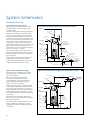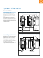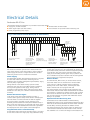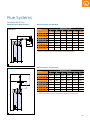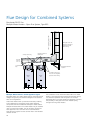
1
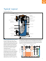
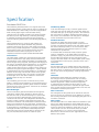
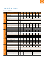
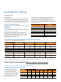
98%
Hamworthy Dorchester DR-FC Evo
Condensing, Room Sealed and Open Flue
Direct Gas Fired Storage Water Heaters
30kW to 120kW Natural Gas or LPG
Continuous outputs 600l/h to 2400l/h
Dorchester DR-FC Evo
Hamworthy offer the Dorchester DR-FC Evo
range of condensing direct gas fired water
heaters in response to the demand for
increased efficiencies in domestic hot water
(DHW) appliances for modern commercial
applications.
Featuring modulating burners and condensing
operation, the Dorchester DR-FC Evo water
heaters provide a high efficiency DHW
solution which can be sized to suit many
applications; and with a wide range of flueing
options supported: room sealed, open flue,
flue schemes B23, C13, C33 and C53, and
very long flue runs up to 100m, these water
heaters can be sited almost anywhere in a
building.
There are 7 models in the Dorchester DR-FC
Evo range from 600 to 2400 litres/hour
continuous output at 44°C temperature rise,
and storage capacities from 227 to 504 litres.
For large loads, multiple water heaters can
be installed, and for a large hot water buffer,
Hamworthy can offer a direct fired unit with
additional storage tanks.
The Dorchester DR-FC Evo can be set for
continuous operation or set to follow its
versatile 21-period/week programmable
timer–with extra period temporary override.
Service programs and an independent
programmable anti-legionella cycle function
are also available.
Timer control allows target storage
temperatures to be set individually for each
programmed water heater ON period so that
the water heater operation can be closely
aligned to the predicted weekly demand
cycle, and optimised for performance or
efficiency priorities at different times as
required.
An intuitive control panel and backlit display
provides the user interface to the water
heater’s comprehensive controls. Operating
status, history, diagnostics, service due etc. can
be displayed at the control panel or remotely
via the optional remote monitoring unit.
Multiple temperature settings to
enhance condensing performance
Exceeds Part L minimum requirements
Electrical anode for corrosion protection
Whisper quiet
Low NOx
Up to 98% seasonal efficiency
Using different hot water temperature
settings during peak load and off peak
periods can enhance energy saving
condensing performance
Options
Natural gas or LPG
Unvented supply kit
Horizontal or vertical flue
terminal kit
Top to bottom pump
recirculation kit
Remote monitoring unit
2
BENEFITS
Condensing Direct Gas Fired Storage Water Heaters
Typical plant room with Dorchester DR-FC Evo condensing water heater and
Purewell VariHeat boilers
Typical Layout
Dorchester DR-FC Evo
Cover
Burner
Hot water outlet
Pressure switch
Combustion
air supply hose
Concentric flue connector
Control panel
Flue gas analysis
test point
Electrical connector block
Temperature sensor T1
Combustion chamber
Potentiostat for
electrical anodes
Electrical anodes
Tank
Flue with silencer
Heat exchanger
Temperature sensor T2
Inspection door
Cold water inlet
Condensate trap
Drain valve
Insulation layer
Pallet base
!H5!/,0-12!+,3452
H
5!/,0-12!+,3452
!! !
"#!
!+,-.!
657!/,0-12!+,3452
6
57!/,0-12!+,3452
8
+
H5!/,0-12!+,3452
,-.!
!49:!;,0<,3-=>3,!
"#!
?,=!+541=
/,0-12 !!
!+,3452
!
!
In this example (see graph) the storage
temperature is set to 70°C during the two
peak demand periods and at 55°C during the
low demand period. In periods of no demand
the water heater is set OFF. Frost protection
is set at 5°C which will switch on the water
heater, overriding the OFF period until the
store temperature reaches 20°C to prevent
water freezing. The anti-legionella cycle is
programmed to run at night, once per week,
heating the water to 65°C for at least 1 hour.
In the peak periods, setting to 70°C ensures demand can be met, both while
the water heater is switched on and for an extended time after switching off,
by using automatic mixing valves to mix with cold water at the taps down
to the required temperature. During the low demand period, the set point is
set to 55°C to prolong condensing operation of the water heater while still
satisfying the maximum demand throughout the period.
High Temperature
Set Point 70°C
High Temperature
Set Point 70°C
70
Anti-Legionella
Set Point 65°C
65
60
55
50
Peak
Demand
Period
!
Lower Temperature
Set Point 55°C
!
Low Demand Period
Peak
Demand
Period
Frost Protection
Set Point 5°C
5
06:00
Anti-Legionella Purge Period
The Dorchester DR-FC Evo timer control
features 21 programmable ON-OFF periods
(3 periods per day/ 7 days per week), with an
individual programmable thermostat set point
per ON period. This allows efficient hot water
schemes to be planned to suit the specific
application, taking into account the required
maximum draw-off at different times of the
day, storage temperature safety philosophy
and temperature required for maximum
condensing operation.
Hot Water Temperature/°C
Flexible Programmable Timer Controls
No Demand Period
12:00
18:00
24:00
Time
3
Specification
Dorchester DR-FC Evo
The Hamworthy Dorchester DR-FC Evo range of direct fired
storage water heaters provide plenty of choice in meeting hot
water demands for a wide variety of commercial applications.
With currently eight ranges in the Dorchester family
comprising over 30 models, the DR-FC Evo range represents
the latest in proven high efficiency condensing technology
to maximise the energy performance and far exceed the
minimum efficiency requirements of the Building Regulations,
Part L.
The Dorchester DR-FC Evo range of water heaters are
manufactured to the highest standards using the latest
production technology to ensure a high quality long lasting
finish in every product configuration. Compliance is assured
with stringent controls in accordance with the European
Standards and each model carrying the CE mark for
compliance with the European standard BS EN 89:2000.
Construction
The water heater cylinders are constructed from high grade
steel and coated with a high quality vitreous enamel lining.
The fabrication of the cylinder and welding is completed fully
before the glass lining is applied, ensuring that the integrity of
the lining is not affected during manufacture. On completion
of the fabrication, the cylinder undergoes a precise glass
coating process where the unit is rotated in every direction to
ensure an even glaze is applied throughout. Surplus material
is drained before the unit is baked at 840ºC to complete the
adhesion of the lining to all internal surfaces of the cylinder,
providing a long lasting finish. The cylinder is covered with
a 50mm layer of CFC free foam insulation to ensure that
standing losses are kept to a minimum.
Burner
The modulating pre-mix burner is mounted on top of the
heater in a down firing arrangement. The controlled supply of
gas and air achieves the optimum gas/air mixture for efficient
performance and clean combustion. The burner can modulate
down to 40% of full power.
Heat Exchanger
The hot combustion gases are directed down through the
combustion chamber which extends to near the base of
the tank then rises up the heat exchanger to a point where
it forms a spiral which descends again, exiting at the flue
connection near the base. This arrangement maximises heat
transfer, as gases cooled by colder water lower down the
tank start to condense. This condensation causes latent heat
energy to be transferred to the cooler water, increasing the
performance of the unit. Condensation formed in this process
is discharged via a condensate trap. This design of the heat
exchanger eliminates the problems traditionally associated
with scale as any build-up will fall away to the base of the
unit, and not affect heat transfer or create hot spots.
4
Condensing Effect
In the heat exchanger process, as the flue gases become
cooler they pass into the lower layer of the tank where the
cold water inlet tops up the supply of water. This maximises
the opportunity to condense, releasing the latent energy in
the process. The condensate in the flue gases is discharged
via the condensate trap at the base of the unit.
Anode Protection
All models are fitted with electrical anodic corrosion
protection as standard, ensuring excellent protection from
corrosion, and being fully effective even with water supplies
that have conductivity as low as 125 micro-siemens. Nonsacrificial anodes are used and these require no routine
maintenance or replacement.
It is essential that the electrical anode protection system
power is maintained i.e. the water heater must have a
permanent supply. Any external time controls must use the
remote enable connections and not interrupt the mains
supply to the water heater. An uninterruptable power supply
is recommended to ensure proper protection of the unit is
maintained.
Clean Out Door
The Dorchester DR-FC Evo models have an easily accessible
clean out door that allows for the inspection and cleaning of
the tank's interior, as required by the recommendations of the
HSC for the control of Legionellosis, including Legionnaires’
disease.
LPG Fuels
All Dorchester water heaters are suitable for LPG fuel.
The fuel type must be specified at the time of ordering.
It is strongly recommended that on LPG installations, gas
detection equipment is fitted and that this equipment
is positioned near the heater and at low level. It is also
imperative that the plant room is ventilated at high and low
level. The LPG variants of the Dorchester DR FC Evo must not
be installed in basement plant rooms.
Flue Connection
The flues gases exit the cylinder at the base of the unit and
return to the top for connection into an adaptor to combine
the incoming combustion air and discharging flue gases into a
concentric connection.
Flue System
The Dorchester DR-FC Evo water heaters are suitable for open
flue or room sealed applications. Room sealed flues can be
discharged through horizontal or vertical concentric terminals.
Twin duct systems are available for longer flue runs, up to
100m. Shorter runs can use concentric ducts up to 40m.
Flue schemes B23, C13, C33 and C53 are supported.
Please refer to the flue section (from page 20) for further
details of flue systems.
Specification
Dorchester DR-FC Evo
Open Vented or Unvented Systems
The water heaters are suitable for open vented water systems
i.e. those fed typically via a header tank and float valve
arrangement. They may also be used in unvented water
systems fed directly from the mains cold water supply if an
optional unvented water supply kit is used.
Unvented Water Supply Kit Option
The optional unvented supply kit is essential for any unvented
application and includes an expansion vessel sized for the
water heater and local pipework only.
Unvented water supply kit option
For large hot water systems or systems with additional storage
tanks, additional expansion vessel capacity may be required.
The unvented supply kit allows the water heater to be fed
directly from the mains water supply or boosted cold water
supply, without the need for header tanks.
Each unvented supply kit is designed to be used with an
individual water heater. Multiple water heater installations
should be provided with one unvented supply kit per water
heater.
The kit contains all the essential components to comply with
the Water Supply (water fittings) Regulations 1999, including
a suitably sized pressure and temperature relief valve, which
locates directly into the water heater.
Each unvented supply kit is sized 1” and comprises the
following items:
■Strainer
■Adjustable pressure reducing valve with tapping points for
inlet and outlet pressure measurement
■Non return valve
■¾” Expansion relief valve, 6 bar
■Temperature and pressure relief valve, 7 bar, 95°C
■24 litre expansion vessel, 3.5 bar cushion pressure.
Designed for Safety
The Health and Safety Commission (HSC) approved code
practice and guidance document L8, makes it clear that
if the risk of Legionella is to be minimised, then the
recommendations must be observed in so far as they relate to
hot & cold water systems. Dorchester water heaters conform
to these requirements as follows:
■Good access for cleaning
■Generous flow and return connections
■Adequately sized drain
■Base designed to avoid sludge traps
■Anodes to reduce metal corrosion
■Number of tappings correctly positioned to facilitate
recirculation, destratification and to obviate stagnation
■Designed to meet unvented supply requirements.
Controlling Legionella
All Dorchester models are designed to meet the Health &
Safety Commission (HSC) requirements for safe production of
hot water, and in particular the control of Legionellosis.
Legionella bacteria are common in natural water sources
and therefore low concentrations may be present in many
water systems. It is important that hot water services are
designed and operated in such a way that these organisms
are prevented from multiplying.
Water temperature is a significant factor in controlling the
risk, with optimum conditions for bacterial growth occurring
between 20°C and 45°C.
Regular cleaning of the system will help to avoid the build-up
of sediments, which may harbour or provide nutrients for the
bacteria.
Water stagnation may encourage the growth of biofilm,
which can provide local conditions that may promote the
proliferation of Legionella bacteria.
Anti-Legionella Controls Function
The Dorchester DR-FC Evo controls incorporate a specific
anti-legionella safety function which can be set to perform a
weekly anti-legionella purge cycle, running the water heater
for a period at a high temperature (default 65°C for one
hour) to prevent the risk of legionella bacteria forming in the
vessel.
This can be set to run automatically during periods when
hot water will not be used, for example to minimise the risk
of scalding. It can also be set to run the system recirculation
pump and/or the optional top to bottom recirculation kit
pump concurrently with the legionella purge cycle to ensure
that the whole system is purged.
5
Controls
Dorchester DR-FC Evo
The Dorchester DR-FC Evo range features advanced control
capability through a digital control panel and backlit display
with adjustable contrast, display illumination time and scroll
speed. Programming the settings is achieved via the neat and
easy to use control panel. The display shows time and day,
actual water temperature, programmed water temperature
and next switching time, on or off. It can also display
operating history, service diagnostics and alert to service due,
based on operating hours.
Controller features include:
■7-day timer control mode
■Hysteresis control
■Extra Period mode (override weekly program)
■Continuous ON or OFF modes
■Frost protection function
■Anti-legionella function
■Programmable external pump control
■Data logging.
Temperature Control and Protection
Electronic temperature control manages accurate flow and
storage temperatures. Temperature sensors are fitted towards
the top and bottom of the unit to monitor temperatures
within the unit and control heating closely for optimum
performance.
■Operating temperature set point range 40°C to 80°C
■Intermediate limit temperature set point 88°C with auto
reset
■High limit temperature set point 93°C, requires manual
reset
■Frost protection temperature set point, 5°C.
7-day Timer Control
The 7-day timer control function allows the Dorchester
DR-FC Evo flexibility to be set up to operate at up to three
periods per day (21 individual periods per week) and to the
appropriate set temperature during those periods, in line
with the applications demand cycle (refer to the example on
page 3). For each individual period the following parameters
are programmable: day of week, heater ON time, heater OFF
time, target temperature (set point) and pump ON/OFF.
Hysteresis Control
Hysteresis controls allow the hot water heating cycle to be
finely tuned. On heat rising cycle, a hysteresis setting will
allow the water temperature to overshoot the set point by a
programmable number of degrees before the heater switches
off, and on a heat falling cycle, another hysteresis setting
will allow a few degrees undershoot below the set point
before switching on the heater. Hysteresis up and hysteresis
down settings are programmable and are used in balancing
the need to prevent cycling against the need to continually
maintain precisely the set point temperature.
Extra Period Operation
In addition to the timer control’s 21 programmable periods,
an extra non-repeating period can be set up using the
Extra Period function. This operates the water heater to a
6
programmed required temperature for a programmed period.
The extra period overrides the timer program for its duration,
and then the extra period settings are cleared on expiration.
ON/OFF Operation
Each water heater can be set to ON or OFF condition whereby
the timer program is disabled and the heater remains in
standby mode. If set to OFF, then frost protection remains
active. It is therefore important that, during maintenance
periods when the water is drained, provision is made for
isolating the unit electrically to ensure non operation. During
ON operation, the water heater switches on if the measured
water temperature is less than the programmed temperature
set point, and heats continuously until the water temperature
reaches the set point.
Frost Protection
Dorchester DR-FC Evo water heaters are supplied as standard
with a frost protection thermostat. When the ON/OFF
switch on the control panel is in the OFF position, the frost
protection system will initiate firing of the burner when
the stored water temperature falls below 5°C to provide
protection against freezing in the cylinder.
Anti-Legionella Function
Refer to the Anti-Legionella Controls Function description on
page 5.
Top-to-Bottom Recirculation Pump Kit (Optional)
In order to prevent stratification within the heater, thus
creating a zone of lower temperature water that can possibly
lead to the proliferation of Legionella bacteria, the optional
top-to-bottom re-circulation kit should be specified. By
constantly returning water from the flow back into the base
of the heater, a uniform temperature is maintained. This
recirculation can be timed to operate in parallel with the antilegionella control function.
Pump Control
The optional recirculation pump or a secondary circuit pump
can be controlled via the pump ON/OFF control function
associated with each timer period, or via the Pump ON/
OFF control in the anti-legionella function. Both functions
drive ON or OFF a single program-controlled 230V power
supply output. This supply can be used for the direct control
of a single pump only (maximum rating 150W). If more
than one pump is to be controlled at the same time by the
water heater, then these should be supplied separately via
contactors and controlled via the program controlled 230V
power supply.
It is possible for a service engineer to set the timed pump
output for permanent operation if desired.
Data Logging and Optional Remote Monitoring
Unit
Water heater data e.g. burning hours, no. of ignitions,
flame errors, and errors history (last 15 faults) are stored
in the controller memory, and available for viewing on the
controller, or at the BMS via the optional remote monitoring
unit, which reformats the data into Modbus format for the
BMS.
Technical Data
Dorchester DR-FC Evo
Energy
Water
Description
Continuous output with 44°C ΔT
(1st hour output)
Continuous output with 50°C ΔT
(1st hour output)
Continuous output with 55°C ΔT
(1st hour output)
Storage capacity
Maximum operating water pressure (open
vented)
Maximum operating water pressure
(unvented)
Expansion relief valve setting (open vented
kit)
Building Regulations thermal efficiency
gross
Nat. Gas G20
20mbar
Gas
LPG G31
37mbar
Flue
Electrical
litres
227
DR-FC
Evo 30
630
(870)
560
(730)
510
(640)
DR-FC
Evo 45
970
(1300)
850
(1100)
780
(930)
DR-FC
Evo 60
1200
(1500)
1100
(1300)
930
(1100)
DR-FC
Evo 80
1700
(1900)
1500
(1700)
1300
(1500)
386
DR-FC
Evo 95
2000
(2200)
1700
(1900)
1600
(1700)
DR-FC
Evo 120
2400
(2600)
2100
(2300)
1900
(2000)
504
bar
8
bar
5.5
bar
5
%
96
98
96
95
97
95
95
Heating-up time, ΔT = 44°C
min.
23
37
24
20
19
16
13
Heating-up time, ΔT = 50°C
min.
26
42
27
23
21
18
15
Heating-up time, ΔT = 55°C
min.
29
46
30
25
23
20
16
kW/24h
4.2
Input, gross–maximum
kW
31.6
32.6
51.2
62.1
85.0
103.4
126.3
Output–maximum
kW
30.5
32.0
49.3
59.3
82.6
98.7
119.4
Standby losses
4.7
6.7
Gas inlet pressure–nominal
mbar
Gas flow rate–[email protected] mbar
and 15°C
m3/h
3.1
3.2
5.0
6.0
8.3
10.1
12.3
Input, gross–maximum
kW
31.0
32.0
50.1
60.8
83.2
101.2
123.6
Output–maximum
kW
30.5
32.0
49.3
59.3
82.6
98.7
119.4
Gas inlet pressure–nominal
Gas flow rate–[email protected] mbar
and 15°C
Approximate flue gas volume @15°C,
9.8% CO2, N.T.P. (Nat. Gas-G20)
Flue gas temperature–maximum
20
mbar
37
kg/h
2.3
2.3
3.7
4.4
6.1
7.4
9.0
m3/h
37.3
38.5
60.2
72.3
103.1
125.5
152.8
°C
45
50
60
65
50
55
60
NOx emission, dry air free,European Class
5. Maximum (at part load)
Pressure at the flue outlet only (B23) with
zero pressure at air inlet
mg/
kWh
52.8
51.0
51.0
47.5
54.6
52.8
51.0
Pa
52
62
133
173
88
126
180
Start current–maximum (maximum power)
A (W)
Run current–maximum (maximum power)
A (W)
Electrical supply
Voltage tolerance
Noise level @2m from flue terminal
Number of (power) anodes
Misc.
l/h
(l)
l/h
(l)
l/h
(l)
DR-FC
Evo 25
600
(730)
530
(630)
480
(560)
Unit
0.59 (135)
0.2 (45)
0.2 (45)
0.61 (140)
0.32 (75)
0.5 (115)
0.41 (95) 0.63 (145) 1.05 (240)
Vac
230 V 1PH 50Hz
% of Vac
-15% +10%
dB(A)
<45
-
1
Weight when empty
kg
202
239
480
Approximate shipping weight
kg
221
260
501
Maximum floor load/ weight filled with
water
kg
429
625
984
2
7
Dimensional Details
Dorchester DR-FC Evo
Condensate
connection
Gas connection
Clearances:
100cm above top of water heater,
100cm around controls and
inspection doors.
50cm around all other sides of
water heater.
Flue connection
Note: Flue gas sampling point
access must be restricted if the
water heater is to be fitted in the
corner of the room. If so, a loose
sampling point adapter is available
as an option, which can be fitting
during installation at a more
accessible position in the flue, as
required.
205
Gas connection
Hot water outlet
Inspection
door
18°
18°
Drain valve position 18°
left/clockwise of cold water
inlet, DR-FC Evo 25–60
T&P valve
Drain valve position18°
right/anticlockwise of cold water
inlet, DR-FC Evo 80–120
Plan View
Gas inlet connection
DR-FC Evo 80–120
(male R ¾”)
Hot water outlet
(male R 1½”)
Gas inlet connection
DR-FC Evo 25–60
(male R ¾”)
Hot water outlet
Gas connection
T&P valve
connection
1”–11.5 NPT
T
Inspection
door
(95x70)
Drain valve
Cold water inlet
(male R 1½”)
(female ¾”)
(female ¾”)
Front View
8
Drain valve
Condensate
connection
(female Rp 1”)
Side View
Dimensional Details
Dimensional Details
Water Heater Model
Ref
Dimensions/mm
DR-FC
Evo 25
DR-FC
Evo 30
DR-FC
Evo 45
DR-FC
Evo 60
DR-FC
Evo 80
DR-FC
Evo 95
A
Total height
C
Position on base
490
1100
D
Water heater diameter
705
850
1485
2005
2060
E
Depth
925
1000
F
Width
850
900
G
Diameter for flue gas discharge
H
Height of flue gas outlet/air supply
100/150
1460
130/200
2000
1995
Hx
x position flue gas outlet
265
310
Hy
y position flue gas outlet
375
440
K
Height of gas connection
1365
1895
1855
M
Height of cold water inlet
265
255
225
N
Height of hot water outlet
1485
2005
2060
P
Height of cleaning opening
265
270
290
R
Height of drain valve connection
180
170
225
S
Height of T&P valve connection
995
1505
1425
T
Height of condensation drain
recirculation18°
kit
V
*Total height with
W
*Height (between pipe centres)
X
*Connections
horizontal
offset
left/clockwise
of cold
water
Y
*Pipe length
Z
*Pipe angle/degrees
220
240
18° 1576
2086
2141
1261
1781
1866
Drain valve position 18°
inlet, DR-FC Evo 25–60
DR-FC
Evo 120
Drain valve position18°
214
right/anticlockwise of cold
water
inlet, DR-FC Evo 80–120
316
318
394
42°
53°
*For/with optional top-to-bottom recirculation kit
50
50
Optional Top-to-Bottom Recirculation Kit Dimensions
30
Front View
M
205
50
X
Z
V
W
Y
All dimensions in mm
234
Plan View
9
System Schematics
Dorchester DR-FC Evo
Unvented Cold Water Supply
Typical pipework arrangement for a single
Dorchester DR-FC Evo water heater on an
unvented system.
The Water Supply (Water Fittings) regulations
1999 require a number of essential controls
pre-set to specific pressure and temperature
settings for unvented systems. To ensure the
controls are correctly sized for the application,
set to appropriate levels and assembled in the
correct order, Hamworthy Heating offer the
unvented kit, a single “water train” with a
separate T&P (temperature and pressure) relief
valve sized to suit the energy input of the
water heater. The T&P relief discharge should
be via an air break to a tundish.
Each unvented supply kit is designed to be
used with an individual water heater. Multiple
heater installations require one unvented kit
per water heater.
Larger systems with additional storage may
require larger capacity expansion vessel.
Open vent pipe
Unvented Cold Water Supply and Single Water Heater
DHW Flow
Flow isolation
valve
Relief
valve
T
Gas isolation
valve
Gas Supply
Temperature &
pressure relief
valve (supplied with
optional Hamworthy
unvented kit)
DHW
Recirculation
Isolation
valve
Optional
Hamworthy
top-to-bottom
recirculation kit
Circulation
pump
Non-return valve
Expansion vessel
Non-return valve
Isolation valve
Pressure reducing valve
Strainer
Mains isolation valve
Condensate drain
Consult with Hamworthy Technical for a full
range of Hamworthy expansion vessels.
Cold feed
Drain valve
Expansion relief valve
Open Vented Cold Water Supply
Typical pipework arrangement for a single
Dorchester DR-FC Evo water heater on an
open vented system.
With open vented systems the feed
and expansion tank must be sized to
provide sufficient cold water storage and
accommodate expanded system water
without the risk of overflowing.
System operating pressure is directly related
to the height of the feed and expansion tank.
Care must be taken therefore to locate the
feed and expansion tank such that it provides
sufficient head pressure so that flow can be
maintained at all outlets likely to be operating
concurrently.
The minimum recommended height of the
bottom of the feed and expansion tank above
the water heater is 2m.
For comprehensive recommendations on the
design, installation and testing of services
supplying water within buildings please refer
to BS 6700.
Optional Hamworthy
unvented kit
Open Vented Cold Water Supply and Single Water Heater
3-way vent valve
Open vent pipe
Flow isolation
valve
DHW Flow
Gas isolation
valve
Feed and
expansion tank
Overflow pipe
T
Relief
valve
Minimum
height 2m
Gas Supply
DHW
Recirculation
Cold
feed
Isolation
valve
Optional
Hamworthy
top to bottom
recirculation kit
Circulation
pump
Non-return valve
Isolation valve
Condensate drain
Drain valve
10
Mains
Cold Water
Supply
Non-return valve
Isolation valve
Mains Cold
Water Supply
System Schematics
Dorchester DR-FC Evo
Unvented System: Two Water Heaters and One Storage Tank
Typical pipework arrangement for two
Dorchester DR-FC Evo water heaters and
an additional storage tank on an unvented
system.
TPRV
TPRV
Top-to-bottom recirculation kit
The loading pump circuit to the hot water
storage tank must be run continuously
throughout all anti-legionella purge periods,
along with secondary circulation and top to
bottom recirculation pumps to ensure the
entire hot water system is fully heated to the
required temperature.
Hot water flow
TPRV
Unvented System: Two Water Heaters
and One Storage Tank
Unvented mains
cold water
supply
Unvented System: One Water Heater and Two Storage Tanks
Typical pipework arrangement for a single
Dorchester DR-FC Evo water heater and two
additional storage tanks on an unvented
system.
TPRV
Loading pump
Consult with Hamworthy technical for a full
range of Hamworthy expansion vessels.
TPRV
Top-to-bottom recirculation kit
When using additional storage tanks with
unvented systems, the expansion vessel
volume must be increased to accommodate
the additional expansion vessels.
Hot water flow
TPRV
Top-to-bottom recirculation kit
Unvented System: One Water Heater
and Two Storage Tanks
Secondary
return
Secondary return
Unvented mains
cold water supply
11
General Applications Information
Dorchester DR-FC Evo Gas, Water Supply, and DHW Circuits
Regulations
CIBSE Publications
The installation of the water heater MUST be in accordance
with the relevant requirements of the Gas Safety Regulations,
Building Regulations, IET Regulations and the Water Supply
(Water Fittings) Regulations. It should also be in accordance
with any relevant requirements of the local gas region and
local authority and the relevant recommendations of the
following documents:
CIBSE Guide H Building Control Systems
These British Standard Codes of Practice and additional
publications have relevant recommendations regarding the
installation of Dorchester DR-FC Evo water heaters.
British Standards
BS 5440 Part 1 Flueing and ventilation for gas appliances
of rated input not exceeding 70kW net. Installation of gas
appliances to chimneys, and for maintenance of chimneys.
BS 5440 Part 2 Flueing and ventilation for gas appliances
of rated input not exceeding 70kW net. Installation and
maintenance of ventilation provision for gas appliances.
BS 6644 Installation of gas-fired hot water boilers of rated
inputs of between 70kW net and 1.8MW net.
BS 6700 Design, installation, testing and maintenance of
services supplying water for domestic use.
BS 6798 Installation and maintenance of gas-fired boilers of
rated input not exceeding 70kW net.
BS 6891 Installation of low pressure gas pipework of up to
35mm (R 1 ¼”) in domestic premises. (2nd family gases).
BS7074 Part 1 Application, selection and installation of
expansion vessels and ancillary equipment for sealed water
systems. Code of practice for domestic heating and hot water
supply.
BS 7671 Requirements for electrical installations. IET Wiring
Regulations. Seventeenth edition.
BS EN 806-2 Specification for installations inside buildings
conveying water for human consumption – Part 2: Design.
I. Gas E. Publications
IGE/UP/1 Strength testing, tightness testing and direct
purging of industrial and commercial gas installations.
IGE/UP/1A Strength testing, tightness testing and direct
purging of small low pressure industrial and commercial
natural gas installations.
IGE/UP/2 Installation pipework on industrial and commercial
premises.
IGE/UP/10 Installation of flued gas appliances in industrial
and commercial premises.
Health & Safety Executive
Guidance note PM5—Automatically controlled steam and hot
water boilers.
12
CIBSE Guide Energy Efficiency in Buildings
CIBSE Commissioning Code B: 2002
CIBSE TM13: Minimising the risk of Legionnaires’ disease.
Department of Health
Health Technical Memorandum 04-01: The control
of Legionella, hygiene, “safe” hot water, cold water and
drinking water systems, Part A Design, installation and
testing, Part B Operational Management
Third Edition of the 1956 Clean Air Act
Memorandum
Department of the Environment, Scottish Development
Department & Welsh Office.
Water System-Open Vented
For Hamworthy Dorchester DR-FC Evo open vented systems,
the feed cistern and water supply from the feed system must
be so sized as to ensure that the make-up water is equivalent
to or exceeds the maximum draw off rate of the heater
systems and any other system requirements. The hot water
flow pipe from each heater must be fitted with a ¾” (20mm)
relief valve and an open vent 1 ¼” (32mm) and a cold feed
1” (28mm) minimum.
No isolating valves should be fitted between the water heater
and the draw off point for relief valve and open vent.
The maximum working head of the heater is 74m (242 feet).
Dead legs to water draw off points should be as short as
possible and in no case should they exceed the lengths laid
down in the water supply (water fittings) regulations. These
regulations state that the maximum lengths of pipe supplying
a hot water draw off tap measured along the axis of the pipe
from the heater, cylinder or tank from a secondary circuit are
as listed below:
Pipes not greater than 19mm I/D—maximum dead leg is
12m.
Pipes in range 19–24mm I/D—maximum dead leg is 7.6m.
Pipes greater than 25mm I/D—maximum dead leg is 3m.
General Applications Information
Dorchester DR-FC Evo
Location
The location chosen for the water heater must permit the
provision of a satisfactory flue system and an adequate air
supply. The location must also provide adequate space for
servicing and air circulation around each unit. This includes
any electrical trunking laid along the floor and to the
appliance.
The water heater mounting surface should be a noncombustible flat and level surface capable of supporting
the weight of the water heater when full of water and any
additional ancillary equipment.
Any combustible material adjacent to the water heater and
the flue system must be so placed or shielded to ensure that
its temperature does not exceed 65°C.
Adequate space to enable installation and servicing should be
provided, with due consideration to ensuring access to the
clean out door and removal of the burner assembly.
Layout
Dorchester DR-FC Evo water heaters are suitable for
installation in either single or multiple configurations. If
additional storage is required to meet peak demands the
water heater can be connected to one or more storage tanks.
If a storage tank is used an additional loading pump and
thermostats are required to ensure proper control over the
stored water temperature.
Water Quality
Due to the variable chemical composition of distributed water
supplies it is necessary to identify the properties of the cold
water feed to the water heater. In common with all types of
water heating equipment, scale will develop during normal
use and it is therefore essential that appropriate steps are
taken to ensure reliable and continuous operation of the
plant.
Contact should be made with the local water provider to
determine the quality of the feed water and reference should
be made to water treatment specialists for appropriate advice.
The water heater warranty requires that the conductivity
of the water in the heater must be no less than 125
microsiemens/cm. This is necessary to ensure effective
operation of the electrical anodic protection system.
There is no upper limit to water hardness, however where
domestic feed water hardness is very high, water treatment
should be considered to reduce the hardness. As hardness
and conductivity are related, care should be taken not to
soften the water to a point where the conductivity falls below
125 microsiemens/cm otherwise the anodic protection will be
rendered ineffective. Harder water produces more scale and
results in more frequent maintenance upstream of the water
heater.
Condensate Discharge
When operating at suitable condensing temperatures, a
condensing water heater has the potential to produce
condensate at up to 13litres per hour per 100kW input
energy.
A drain connection is fitted to the boiler to enable the
disposal of condensate, which is mildly acidic, with a typical
value 3.5pH, and can be disposed of normally through the
drainage system. If in any doubt about local regulations,
check with the local water authority.
The condensate drain on each water heater must be
connected to a suitable drainage system using corrosion
resistant material such as PVC plastic with glued sealed joints
to prevent escape of condensate.
Drain traps and an open tundish should be incorporated into
the design, and the pipework given appropriate protection
from physical damage and frost.
The pipework should be installed with at least a 3 degree fall
(approximately 50mm per metre).
Delivery
Dorchester water heaters are delivered factory assembled and
mounted within frames, shrink-wrapped and on a steel pallet
base which is fitted permanently to the unit.
All Hamworthy products are delivered to site on a tail-lift
vehicle, and deliveries are closely co-ordinated with the
customer, to suit the site construction programme. Standard
delivery is to ground level from the tail-lift vehicle. To enquire
about special delivery services, please contact our customer
services team.
Commissioning
Hamworthy Heating Ltd strongly recommends that all water
heaters are commissioned by their service department,
who will issue an appliance log-book that details the initial
operating settings, and which can be used to record all future
maintenance work.
For more information on commissioning contact Hamworthy
Heating Service Department.
Tel 0845 450 2866
or email [email protected]
Maintenance
Installed water heaters will experience a wide variation in
operating conditions that can occur due to differing patterns
of usage and the variable chemical nature of distributed
water supplies. It is therefore strongly recommended that
water heaters be drained and inspected within 3 months
of the initial commissioning. Once the levels of calcium
deposition are established a suitable maintenance schedule
can be implemented, however as a minimum all water
heaters should be serviced annually.
Warranty
The Dorchester DR-FC Evo water heater carries a standard
two year warranty on parts. Where the product is
commissioned by Hamworthy Service Engineers, then the
warranty also covers labour for the warranty period, subject
to servicing and warranty conditions.
13
Air Supply and Ventilation
Dorchester DR-FC Evo
An adequate supply of fresh air for combustion and ventilation must be provided in accordance with BS5440 and BS644. Where
Dorchester DR-FC Evo water heaters are installed as room sealed units, the air supply is for ventilation only. Air supply and
ventilation must be sized for the entire plant. The combined net heat input of all gas fired appliances within the plant room or
compartment must be used for these calculations.
Water Heater Installations <70kW Net Rated Input
Air supply and ventilation must be in accordance with BS5440
Compartment Ventilation – Open Flue
Compartment Ventilation – Room Sealed
Direct to outside air
To room or
internal space
Direct to outside air
To room or
internal space
High level–5cm2/kW net input
High level–10cm2/kW net input
High level–5cm2/kW net input
High level–10cm2/kW net input
Low level–10cm2/kW net input
Low level–20cm2/kW net input
Low level–5cm2/kW net input
Low level–10cm2/kW net input
The areas quoted are minimum free areas for ventilation grilles. For further guidance refer to BS5440.
Plant Installations with Combined Heat Input >70kW Net
Air supply and ventilation must be in accordance with BS6644.
Open Flue Appliances
Compartment Ventilation –
Open Flue
Plant Room Ventilation – Open Flue
Direct to outside air
Direct to outside air
net input
High level–2cm2/kW net input
Low level–10cm2/kW net input
Low level–4cm2/kW net input
High
level–5cm2/kW
Room Sealed Appliances
Compartment Ventilation –
Room Sealed
Compartment Ventilation –
Room Sealed
Plant Room Ventilation –
Room Sealed
Direct to outside air
To room or internal space
Direct to outside air
High level–typically
5cm2/kW
net input
Low level–typically 5cm2/kW net input
net input
High level–typically 2cm2/kW net input
Low level–typically 10cm2/kW net input
Low level–typically 2cm2/kW net input
High level–typically
10cm2/kW
The areas quoted are minimum free areas for ventilation grilles. For net heat input, refer to technical data table on page 7.
For further guidance refer to BS6644.
General Ventilation Requirements
Plant Room Temperatures
Additional requirement of BS6644 for multiple boiler
installation requires that the air supplied for plant room
ventilation shall be such that the maximum temperatures
within the plant room do not exceed:
High and low level ventilation grilles shall communicate
with the same room or internal space where compartment
ventilation is used. Where ventilation grilles communicate
directly with outside air they shall be positioned on the same
wall.
■At floor level, or 100mm above floor level: 25°C
Air Supply
■At mid-level, 1.5m above floor level: 32°C
The air supply should be free from contamination such as
building dust and insulation fibres from lagging. To avoid
unnecessary cleaning and servicing of the boiler modules
the boilers should not be fired whilst building work is being
undertaken.
■At ceiling height, or 100mm below ceiling height 40°C.
Ventilation Grille Openings
High and low level ventilation grilles shall be positioned as
high and as low as practicable. Low level grills additionally
shall be located within 1m of floor level for Natural gas and
within 250mm of floor level for LPG. High level grilles are
recommended to be positioned within 15% of the boiler
height form the ceiling.
14
Summer Operation
Where a boiler installation is to operate throughout the
summer months, e.g. for domestic hot water production
for more than 50% of the time, then additional ventilation
allowances are required. Refer to BS6644 for more
information.
Electrical Details
Dorchester DR-FC Evo
The following electrical connections are provided on each water heater:
■Supply live, neutral and earth
■Remote enable of water heater
■Alarm signal output (volt free contact)
■Bus connection for optional remote monitoring unit.
■Timer programmed pump output
Fig 1 Control Panel Terminal Block (top of water heater)
1
2
N
L
3
4
5
6
7
8
9
10
11
X1
X2
12
13
N
14 15
16
17 18
19
L
20
21 22
23
24
X3
X5
X6
X4
{
Supply 230V 1Ph 50Hz
fused 6 amps
Volt-free switch
Timer program
controlled pump
across X1 and X2,
(pump not HHL supply)
for externally
supplied (max 230V)
remote alarm/fault
signal circuit.
Electrical Connections
The electrical connection junction box is located within the
upper casing section of the water heater to accept cables for
power supply and controls. A single terminal rail is located
within this junction box for all external connections.
Power Supply
An independent isolator and fused electrical supply is required
for each water heater and remote monitoring unit for
interfacing with a building management system (BMS). Supply
230 volt, 50Hz, single phase.
Wiring external to the heater and any optional remote
monitoring unit must be in accordance with IET regulations
and any local regulations which apply. Wiring must be
completed in heat resistant cables, and mains supply cables
should be 3-core cable, size 1.00mm2. External fuses should
be 6 Amp.
Remote Alarm/Fault Signal
In the event of the water heater developing a fault, a
common alarm signal is raised, which closes a normally-open
volt-free switch to connect terminals X1 and X2 together.
This can be used to complete a circuit switching on an
externally powered (maximum 230V) fault indication lamp or
alarm circuit (not HHL supply). At the same time as the switch
is made, an error code associated with the fault is generated
and displayed at the control panel to aid fault diagnosis.
Programmable Timer-controlled Pump
A 230V 50Hz single phase timer-controlled supply is provided
for the direct control of a single pump only (maximum rating
X1
X2
N
TX+ TX–
L
{
Bus
connection
Optional
remote
monitoring
unit
Output, 24V
remote enable of
water heater
(requires external
volt-free switch)
Modbus
communication
output from
optional remote
monitoring unit
to BMS
Supply 230V 1Ph 50Hz
fused 6 amps
150W) for system recirculation or top-to-bottom recirculation.
If more than one pump is to be controlled at the same time
by the water heater, then these should be supplied separately
via contactors using the program controlled 230V power
supply as the switching control signal. Pump operation can
be co-ordinated to operate in tandem with the anti-legionella
cycle as well as any programmed ON period.
Remote Enable
For external timer, BMS control, or remote manual control,
each water heater can be controlled via a remote enable
circuit, which, if enabled, switches ON the combustion
heating circuit of the water heater, overriding the water
heater’s internal time clock program while ON.
The remote enable circuit operates at 24V supplied by the
water heater with the water heater enabled when X3 and X4
are connected. Therefore any external control relay or switch
wired across X3 and X4 must use volt-free contacts rated to
24V 1A with resistance no greater than 150Ω when closed.
Wiring is not provided.
Optional Remote Monitoring Unit
Stored data can be made available to a BMS (Building
Management System) via an optional Remote Monitoring Unit
which act as an interface between the water heater controller
and the BMS, converting the data into Modbus format.
The remote monitoring unit requires 230V 1ph 50Hz supply.
Communication between the water heater remote monitor
unit and BMS is via a 2-wire low-voltage communication bus.
15
Application
Application &
& System
System Data
Data
Unvented Hot Water Systems
Unvented Hot Water Systems
Unvented Hot Water Systems
Following revision of the model water
Followinginrevision
of the
water
bye-laws
1986 and
themodel
subsequent
bye-laws
in
1986
and
the
subsequent
publication of part G3 of the Building
publication ofprovisions
part G3 of
theissued
Building
Regulations,
were
Regulations,
provisions
were issued
for
the essential
safety requirements
for the essential
safety requirements
necessary
on unvented
hot water
necessary
on
unvented
hot water
storage systems. These requirements
storage
systems.
requirements
are
covered
in lawThese
by the
introduction
are“The
covered
in law
by the
introduction
of
Water
Supply
(Water
Fittings)
of
“The
Water
Supply
(Water
Fittings)
Regulations 1999.”
Regulations
1999.”
The safety system comprises of a
The safety
comprises
a
number
of system
essential
controls of
pre-set
to
number and
of essential
controlspressure
pre-set to
specific
very important
specific
and very important
pressure
and
temperature
levels. To ensure
that
and
temperature
levels.
To
ensure
the controls are correctly sized for that
the controls set
areto
correctly
sized levels
for
application,
appropriate
application,
set in
to the
appropriate
levels
and
assembled
correct order,
and assembled
in thehave
correct
order,
Hamworthy
Heating
elected
to
Hamworthy
Heatingkithave
to
offer
the unvented
as aelected
single preoffer the unvented
kit as a single
preassembled,
WRAS approved,
water
assembled,
approved,
water
‘train’
with aWRAS
separate
temperature/
‘train’ with
a separate
temperature/
pressure
relief
valve sized
to suit the
pressure
reliefofvalve
sized to suit the
input
energy
the heater.
input
energy
of
the
heater.
This policy considerably simplifies site
This policy considerably
simplifies
installation
leaving the installer
to site
installation
leaving
the
installer
connect from the water main totothe
connecttrain’
fromand
thefrom
waterthe
main
toto
the
‘water
train
the
‘water train’ and from the train to the
heater.
heater.
A
dedicated socket is provided on
A dedicated
socket
is Evo
provided
all
Dorchester
DR-FC
wateron
all Dorchester
DR-FC
heaters
exclusively
for Evo
the water
fitment of
heaters
exclusively
forpressure
the fitment
the
temperature
and
reliefof
the
temperature
and
pressure
relief be
valve, the discharge of which should
valve,
the
discharge
of
which
should
be
via an air break to a tundish.
via
an
air
break
to
a
tundish.
Each unvented system kit is supplied
Each aunvented
system kitvessel
is supplied
with
24 litre expansion
to
with a 24 litre the
expansion
to
accommodate
stored vessel
hot water
accommodate
the
stored
hot
water
expansion from the water heater. Due
expansion
fromnature
the water
heater.
to
the variable
of hot
waterDue
to the variable
natureexpansion
of hot water
circuits
an additional
vessel
circuits
additional
expansion vessel
required
to accommodate
may
be an
to accommodate
may be required
expansion
from the
hot water store
expansion
the hotpipework
water store
within
the from
distribution
or
within
the
distribution
pipework
or
additional storage tanks where used.
additional
storage
tanks
where
used.
Hamworthy can supply a range of
Hamworthyvessels
can supply
range
of
expansion
up to a1000
litre
expansion
vesselsfor
uppotable
to 1000hot
litrewater
capacity
suitable
capacity to
suitable
for potable
hot water
systems
suit most
requirements.
systems
to
suit
most
requirements.
For comprehensive recommendations
For the
comprehensive
recommendations
on
design, installation
and testing
on services
the design,
installation
testing
of
supplying
waterand
within
of servicesattention
supplying
building,
is water
drawnwithin
to the
building, attention
drawn
to the
appropriate
sectionsis of
B.S. 6700
appropriate
sections
of
B.S.
6700
1997, particularly clause 4 of
1997, particularly
clause 4 of
section
2.
section 2.
13
13
16
Hamworthy Unvented Kit
Hamworthy Unvented Kit
Temperature
and
pressure
Temperature
relief
valve
and pressure
relief valve
Non-return
valve
Non-return
valve
Pressure
Pressure
Non-return
valve
Non-return
valve
Expansion Vessel Sizing Calculation
Expansion
Vessel vessel
Sizingvolume
Calculation
Required
expansion
(V2) can be calculated using the following
Required
expansion
vessel
volume
(V2) can be calculated using the following
formula:
formula:
Σ x V1
V2 =
V2 = 1 –Σ PxCV/P1 W
1 – PC /PW
Where V2 = Required expansion vessel
Where V
V12 =
expansion
= Required
Total system
volumevessel
(cylinder plus pipework)
= Water
Total system
volume
(cylinder plus pipework)
V
expansion
factor
Σ1 =
=
Water
expansion
factor
Σ
PC = Expansion vessel cushion pressure (absolute) + 1 bar
= Working
Expansionpressure
vessel cushion
pressure
(absolute)
+1
bar + 1 bar
C =
PPW
(absolute)
= Expansion
valve
setting
PW = Working pressure (absolute) = Expansion valve setting + 1 bar
Expansion Factor for Different Water Temperatures
Expansion Factor for Different Water Temperatures
50
55
60
65
70
Temp °C
50
55
60
65
70
Temp °C
0.0142
0.0168
0.0196
0.0225
Expansion factor Σ 0.0118
0.0142
0.0168
0.0196
0.0225
Expansion factor Σ 0.0118
Basic Pipework Volume Calculation
Basic
Pipework
Volume
To
calculate
pipe volume
forCalculation
use in expansion vessel sizing calculation, use the
To calculate pipe volume for use in expansion vessel sizing calculation, use the
formula:
formula:
2
Where
Where
and
and
Volume (litres) per metre = 0.0031428 x r 2
(litres)
metre
= 0.0031428
x r thickness), in mm
rVolume
= Internal
radius per
= ((½
x Outside
Diameter) - wall
rL =
Internal
radius
=
((½
x
Outside
Diameter)
wall
thickness), in mm
= length of pipe, in metres
L = length of pipe, in metres
Example
Example
For
a 10m length of EN 1057 copper pipe, 22mm outside diameter, with wall
For a 10m0.9
length
ENinternal
1057 copper
22mm- 0.9)
outside
diameter, with wall
thickness
mm,ofthe
radius pipe,
r = ((22/2)
= 10.1mm.
thicknessof0.9
mm,per
themetre
internal
radius r = ((22/2)
- 0.9) = 10.1mm.
Volume
water
= 0.0031428
x r2
Volume of water per metre =
= 0.0031428
0.0031428 xx 10.1
r2
x 10.1
=
0.0031428
x
10.1 x 10.1
= 0.3206 litres/metre
= 0.3206
litres/metre
Therefore total volume of water
in 10m
of pipe is 10 x 0.3206 = 3.206 litres.
Therefore total volume of water in 10m of pipe is 10 x 0.3206 = 3.206 litres.
Hot Water Sizing
Guidance Notes
The following notes are given for guideline purposes and the assumptions
made are general. The diversification of hot water requirements are great and
each particular application must be examined in detail.
General Guidelines
There are applications where sizing a water heater is a straightforward
exercise. An obvious example is an industrial hot water load for a process
requiring a specific amount of hot water, in a specified time at a specified
temperature. All that is required is the lowest cold water supply temperature
and the heater(s) output can be directly related to the amount of hot water
required. If the load is continuous the heater or heaters must be sized to cope
with the full amount. If the load is intermittent consideration can be given to
a smaller heater installed in conjunction with a suitably sized storage tank.
Other types of installations which can be easily sized are sports pavilions and
leisure centres, especially those catering for team games, when a known
number of people will use showers, baths etc. at a known time. This is in
effect the peak load when a large quantity of hot water may be dumped
quickly since all showers may be running continuously. For sizing it is
necessary to determine the duration of continuous use, which will depend
on the maximum number of players using the showers. Showers can save
water, but one shower running continuously for 1 hour can dump 328 l.
Multiplied by 10 or 20 this can represent a large load which is best catered for
by storage with a long recovery time. However, due consideration should be
given to additional heaters and lower storage on the grounds of standby and
cost.
The third category comprises almost all other commercial and industrial
applications where hot water demand is random. To size the hot water
requirement it is necessary to determine when the demand is greatest.
Obviously if the water heater can cope with the peak demand, the remainder
will be adequately catered for. However, the heater cannot be sized on the
assumption that all outlet appliances will run continuously for 1 hour since
this will result in gross over-sizing of heaters. Simple guidelines and common
sense must be used to estimate appliance usage.
Listed below are a series of guidelines which may prove helpful in sizing
Hamworthy water heaters.
Restaurants, Kitchens, etc., Serving Main Meals
Each meal will use: 9 litres at 60°C made up from: 3 litres preparation, 6 litres
washing up.
Hotels and Motels
Assume average occupancy as 1½ people
per room unless specified as single rooms.
Generally the peak will occur over a two
hour period in the morning (7am-9am).
In specialised hotels catering for specific
functions (i.e. conferences) the peak could
be reduced to one hour. For medium sized
hotels with 100-200 people allow 25-35 litres
hot water per person over two hour peak
period. For smaller hotels allow more per
person-for larger hotels allow slightly less.
These figures assume that mainly showers are
used, one per room.
Always check restaurant load to ensure that
peak morning capacity will cover it. Overall,
allow 115-135 litres per guest per day.
Dormitories
Allow 15 litres per man, 20 litres per woman
over a peak 1 hour period.
Flats and Apartment Blocks
Assume average occupancy of 2½ people per
flat. Allow 38 litres per person over a peak 3
hour period.
Rest and Convalescent Homes - with
Kitchen and Laundry
Allow 38 litres per person over a peak 3 hour
period.
Industrial Shower Rooms
Assume shower period to be 20 minutes at
the end of each shift and that all showers
and wash taps are running continuously for
this period at full flow i.e. dump load ideal
for heater plus storage application.
School Changing Rooms
The peak period would be spread over 1, 2 or 3 hours etc., depending on the
establishment.
Assume all showers and wash basins are used
at full flow for 10 minutes after each gym
period.
Bar sinks—allow 114 litres per hour.
Offices
School kitchens in general use 30% less than restaurants but allowance
should be made for the number of sittings.
Allow 1.5 litres per person per hour for 1
hour peak load.
Commercial Laundry
Allow 13 litres per kg of wash at 71°C.
17
Hot Water Sizing
Guidance Notes
Launderettes
The following tables give the approximate flow rates for
standard hot or mixed water fittings and the approximate
capacity in normal use. By appraising what function
appliances perform it is possible to determine peak usage i.e.
three baths per hour, two showers each of 10 minutes, sinks
filled one per hour, etc.
Determine the cycle time of the machines (add 10 minutes
for unloading and reloading). Calculate the number of cycles
that occur in one hour and multiply the number of machines
and then multiply by the amount of hot water used by one
machine in one cycle to arrive at the maximum demand.
Hairdressers and Beauty Salons
Flow Rate/
litres/second
Fitting
Allow 280 litres per hour of water at 60°C per wash basin per
peak demand.
Hospitals etc.
Demand will depend on the type of hospital, nursing home,
etc. Overall consumption per person per day of hot water can
range between 70 litres - 230 litres.
In all applications it is desirable to cross check general
assumptions with actual flow rates and capacities and in
applications where no general guidelines exist it may be
necessary to calculate hot water demand by listing the
number and type of appliance in use.
Wash basin tap
0.15
Wash basin spray tap
0.05
Bath tap
0.30
Sink tap 15mm
0.20
Sink tap 20mm
0.30
Shower spray head
0.15
Shower 100mm rose
0.40
Approximate Mixed, Hot and Cold Capacities of Appliances in Normal Use
Cold water 10°C, hot water 60°C, mixed water 40°C
Appliance
Capacity in Normal
Use/ litres
Amount of Hot Water/
litres
Amount of Cold Water/
litres
Temperature in Use/
litres
Wash basin
5
3.0
2.0
40
Bath
80
48.0
32.0
40
Small sink
12
7.2
4.8
40
Large sink
18
10.8
7.2
40
1 min shower spray
9
5.4
3.6
40
5 min shower spray
45
27
18.0
40
1 min shower
(100mm rose)
24
14.4
9.6
40
5 min shower
(100mm rose)
120
72.0
48.0
40
The quantities of hot water shown above are only correct to those particular temperatures. For other combinations use the
following formula to determine the proportion of hot water.
Quantity of hot water = capacity of appliance x
Mixed water temperature – Cold water temperature
Hot water temperature – Cold water temperature
Factors at Various Cold Water and Mixed Water Temperature
for Determining Hot Water Quantity at 60°C
As a further example, the table
opposite gives the factors by which
the capacity of an appliance is
multiplied to obtain the quantity of
hot water required when stored at
60°C for various cold water supply
temperatures and various mixed
water temperatures.
18
Cold Water
Supply
Temperature
Mixed Water Temperature
60°C
55°C
50°C
45°C
40°C
35°C
30°C
5°C
1.0
0.91
0.82
0.73
0.64
0.55
0.45
10°C
1.0
0.90
0.80
0.70
0.60
0.50
0.40
15°C
1.0
0.89
0.78
0.67
0.55
0.44
0.33
20°C
1.0
0.88
0.75
0.63
0.50
0.38
0.25
Hot Water Sizing
Dorchester DR-FC Evo
Having established the number of
appliances, the usage, and the quantity
of hot water required, the outputs
of the heaters must be related to the
hot water storage temperature. Any
decrease in the cold water supply
temperature or increase in the hot
water storage temperature will result
in a decreased output from the heater.
is the maximum rise expected across
the heater with a cold water supply
temperature of 5°C. It is possible
however that for certain applications
a higher storage temperature will
be required when, if the cold water
supply temperature remains
at 5°C the calorifier outputs
will be further reduced.
The output figures given are based
on a rise in the temperature of 44°C
i.e. with a storage temperature of
60°C the cold water supply must be
at 16°C. The following table indicates
the continuous output capability
of each water heater at different
values of temperature rise across the
heaters. (Flow temperature - cold feed
temperature).
The question of additional storage
if required and how much should
be looked at in light of general
consumption throughout the day,
recovery times, whether the peak
period is spread over 1 hour
or 3 hours and whether a larger
storage buffer than the calorifiers
own storage is required to guard
against the possibility of high flow
rates at peak time.
The normal maximum storage
temperature is 60°C and hence 55°C
Where the installation requires the
use of large volumes of hot water
over short periods and a storage tank
is specified, a loading pump will be
required to transfer hot water from
the calorifier into the storage tank.
This should be a bronze pump and
sized to suit the continuous output
of the water heater under design
temperature conditions.
It is important that cold water supply
capacities and pressures as well as
pipe work layouts are suitable for
high volume draw off at peak times
to ensure satisfactory hot water
delivery to draw off points.
One or more storage tanks may be
used in conjunction with Powerstock
calorifiers to satisfy hot water demand.
Maximum Continuous Output (litres/hour) at Different Levels of Temperature Rise across Water Heater
from Cold Feed to Hot Flow
Maximum Continuous Output
Model
Units
Temperature rise across Water Heater (Flow temperature – cold Feed temperature)
40°C
44°C
50°C
56°C
60°C
70°C
DR-FC Evo 25
l/h
660
600
530
471
440
380
DR-FC Evo 30
l/h
693
630
560
495
462
400
DR-FC Evo 45
l/h
1067
970
850
762
711
610
DR-FC Evo 60
l/h
1320
1200
1100
943
880
730
DR-FC Evo 80
l/h
1870
1700
1500
1336
1247
1100
DR-FC Evo 95
l/h
2200
2000
1700
1571
1467
1300
DR-FC Evo 120
l/h
2640
2400
2100
1886
1760
1500
Powerstock Storage Tanks
Hot Water Storage
Powerstock hot water storage tanks
are the perfect partner for Dorchester
water heaters where large volumes of
hot water are required with intermittent
use.
Available in 300, 500, 750 and 1000
litre capacities, these high quality glass
lined storage tanks can be installed
in single or multiple configurations to
match the hot water demand.
Powerstock storage tanks are WRAS
approved and suitable for both
unvented and open vented applications.
Options
Unvented supply kit
Top to bottom pump
recirculation kit
Electrical anode protection
Electric immersion
heater kit
For further details of Powerstock Storage
Tanks, refer to brochure 500002488.
19
Flue Systems
Dorchester DR-FC Evo
The Dorchester DR-FC Evo water heaters are designed to
operate as room sealed appliances or in open flue systems,
and are available with a choice of flue options using a range of
matched components to provide versatility in where the water
heater can be located. Options are available for room sealed
concentric or twin duct, or open flue single pipe arrangements.
Balanced flues can reduce the cost of installation and simplify
flue runs. Room sealed configurations reduce the volume of
ventilation air required, resulting in tighter and more energyefficient buildings. Open flue applications provide solutions
where balanced flue terminals are unsuitable, or where
existing flue routes are to be retained.
Flue System Construction
The flue system must be capable of handling saturated flue
gases. Flue construction should be fully welded and CE
marked for positive pressure application. All Hamworthy
flue components have been matched and tested specifically
for use with these water heaters. This ensures optimum
performance from the installation and simplifies the necessary
sizing calculations.
The flue is constructed from aluminium for twin duct and
open flue arrangements (single wall) and for the inner wall of
concentric flue components. The outer wall of concentric flue
components is constructed from galvanised steel, with the
concentric ring carrying the combustion air to the appliance,
which also acts as the insulation to the inner duct, which
carries the exhaust flue gases.
Flue pipes are joined with a simple push fit connection with a
silicone seal ensures water and pressure tight joints every time
and clamp bands complete the installation.
Single Water Heaters with Individual Flue System
Each individual Dorchester DR-FC Evo can be installed with
a flue system from either the room sealed or open flue type
solutions. Room sealed units must be installed with individual
air supply ducts and flue discharge systems.
Multiple Water Heater Flue System Design—Open
Flues System Only
PD CR 1749:2001 Flue Scheme Definitions
Room Sealed
Type C - An appliance in which the combustion circuit
(air supply, combustion chamber, heat exchanger and
evacuation of the products of combustion) is sealed with
respect to the room in which the appliance is installed.
Type C1 - A type C appliance that is designed for
connection via its ducts to a horizontal terminal, which at
the same time admits fresh air to the burner and discharges
the products of combustion to the outside through orifices
that are either concentric or close enough to come under
similar wind conditions.
Type C3 - A type C appliance that is designed for
connection via its ducts to a vertical terminal, which at the
same time admits fresh air to the burner and discharges the
products of combustion to the outside through orifices that
are either concentric or close enough to come under similar
wind conditions.
Type C5 - A type C appliance connected to separate ducts
for the supply of combustion air and the evacuation of
the products of combustion. These ducts may terminate in
zones of different pressure.
Type C13 - A type C1 appliance incorporating a fan
upstream of the combustion chamber/heat exchanger.
Type C33 - A type C3 appliance incorporating a fan
upstream of the combustion chamber/heat exchanger.
Type C53 - A type C5 appliance incorporating a fan
upstream of the combustion chamber/heat exchanger.
Open Flue
Type B - An appliance intended to be connected to a flue
that evacuates the products of combustion to the outside
of the room containing the appliance. The combustion air is
drawn directly from the room.
Type B2 - A type B appliance without a draught diverter.
Type B23 - A type B2 appliance incorporating a fan
upstream of the combustion chamber/heat exchanger.
For details of the full range of classifications refer to BSI
publication PD CR 1749:2001.
20
It is permissible to install multiple Dorchester DR-FC Evo water
heaters on open flue systems only. Water heaters using room
sealed flues should be installed with individual flue systems,
and not connected into a header type arrangement for the
ducted air supply nor flue discharge.
Flues Scheme Definitions
Flue systems are defined in accordance with European
schemes defined in PD CR 1749:2001 and summarised in the
table at the bottom of this page.
Supported Flue Schemes
The Dorchester DR-FC Evo water heater supports the
following flue schemes:
Room Sealed Flue Systems
■Concentric flue systems type C13–Horizontal termination
■Concentric flue systems type C33–Vertical termination
■Twin duct flue systems type C53–Vertical flue termination
with Horizontal air inlet
Conventional Open Flue Systems
■Open flue systems type B23–Vertical termination
Note. Open flue applications can use the same flue
components as the twin duct room sealed system.
Ordering Flues
Flues are ordered separately from the water heater. To
simplify the selection process, Hamworthy have a flue order
form available for the Dorchester DR-FC Evo.
To order flues, telephone 0845 450 2865 or email sales@
hamworthy-heating.com to request an order form, and state:
■Water heater model
■Installation type (B23, C13, C33 or C53)
Flue Systems
Dorchester DR-FC Evo
Open Flue Systems, Type B23
Dorchester DR-FC Evo open flues are arranged for air supply directly from the plant room with vertical flue discharge.
Ducting between the heater and the flue terminal is made using single tubes. Table 1 provides details of the maximum flue length
and equivalent bend lengths.
Where longer flue routes are required then it is possible to increase the diameter for the flue duct between the heater and the
flue terminal. The final connection diameters at the heater and the flue terminal remain the same, so expansion and reduction
pieces are used to facilitate the diameter change at each end of the flue pipe. Table 2 provides details of the maximum flue
length and equivalent bend lengths.
Table 3 summarises the maximum flue pressures for all applicable flue system types.
Table 1–Open Flue With Vertical Flue Terminal, Type B23-A
Diameter/mm
Model
DR-FC Evo 25
B23
Elbow equiv. length/m
Maximum
Length/m
100
55
C13
DR-FC Evo 30
100
55
DR-FC Evo 45
100
55
C33
90°
45°
4.6
1.2
4.6
1.2
4.6
1.2
DR-FC Evo 60
100
55
4.6
1.2
DR-FC Evo 80
130
65
2.4
1.4
DR-FC Evo 95
130
65
2.4
1.4
DR-FC Evo 120
130
65
2.4
1.4
C53
Table 2–Open Flue With Enlarged Diameter Duct Between Heater And
Terminal, And Vertical Terminal, Type B23-B
Terminal
100
100
90°
45°
100
2.4
1.4
2.4
1.4
2.4
1.4
130
100
100C33
DR-FC Evo 45
130
100
100
DR-FC Evo 60
130
100
100
DR-FC Evo 80
150
130
100
DR-FC Evo 95
150
130
DR-FC Evo 120
150
130
W
C13
DR-FC Evo 30
Y
Elbow equiv. length/m
V
DR-FC Evo 25
B23
Duct
Maximum
Length/m
2.4
1.4
2.6
1.6
100
2.6
1.6
100
2.6
1.6
Y
Diameter/mm
Model
C53
Table 3–Maximum Flue Gas Pressure For B23,
V C13, C33 And C53 Type Flue Systems
Outlet only (B23)
Poutlet/mBar
Pinlet /mBar
Poutlet/mBar
0
0.52
-0.26
0.26
0
0.62
0
1.33
DR-FC Evo 60
0
DR-FC Evo 80
0
Y
-0.32
0.32
-0.69
0.69
1.73
-0.90
0.88
-0.47
V
DR-FC Evo 30
DR-FC Evo 45
0.90
Y
DR-FC Evo 25
Inlet + Outlet (C13, C33 and C53)
Pinlet /mBar
W
X
Model
Maximum Flue Gas Pressure
X
W
0.47
DR-FC Evo 95
0
1.26
-0.67
0.67
DR-FC Evo 120
0
1.80
-0.96
0.96
V
21
X
W
Flue Systems
Dorchester DR-FC Evo
Concentric, Room Sealed Flue Systems Type C13
The Dorchester DR-FC Evo can be flued with horizontal discharge through concentric terminals.
Ducting from heater to terminal can be made using concentric tubes. Table 4 provides details of the maximum length of flue and
the permitted number of bends within an individual flue system.
Where longer flue routes are required it is possible to use individual air supply and flue ducts heater converging at the concentric
terminal, reducing the flue system resistance and permitting the extended length. Table 5 provides details of the maximum flue
length and equivalent bend lengths.
If still longer flue lengths are required then it is possible to increase the diameter for the air supply and flue ducts between the
heater and the terminal. The final connection sizes at the heater and concentric terminal remain the same, so expansion and
reduction pieces are used to facilitate the size change at each end of both the air supply and flue pipe. Table 6 provides details of
the maximum flue length and equivalent bend lengths.
Table 3 on page 21 summarises the maximum flue pressures for all applicable flue system types.
Table 4–Concentric Balanced Flue With Horizontal Terminal, Type C13-A
Model
C13
Diameter/mm
C33
C53
Maximum
Length/m
Max. no. of 45° or
90° bends
40
7
DR-FC Evo 25
100/150
DR-FC Evo 30
100/150
40
7
DR-FC Evo 45
100/150
40
7
DR-FC Evo 60
100/150
40
7
DR-FC Evo 80
130/200
15
4
DR-FC Evo 95
130/200
15
4
DR-FC Evo 120
130/200
15
4
Table 5–Parallel Balanced Flue With Concentric Horizontal
Terminal, Type C13-B
Diameter/mm
DR-FC Evo 25
DR-FC Evo 30
X
W
100/150
45°
55
4.6
1.2
55
4.6
1.2
100/150
55
4.6
1.2
DR-FC Evo 60
100
100/150
55
4.6
1.2
DR-FC Evo 80
130
130/200
65
2.4
1.4
DR-FC Evo 95
130
130/200
65
2.4
1.4
DR-FC Evo 120
130
130/200
65
2.4
1.4
Table 6–Enlarged Parallel Balanced Flue With Concentric Horizontal
Terminal, Type C13-C
Model
Diameter/mm
Maximum
Length/m
Elbow equiv. length/m
Duct
Terminal
130
100/150
DR-FC Evo 30
130
100/150
100
2.4
1.4
DR-FC Evo 45
130
100/150
100
2.4
1.4
DR-FC Evo 60
130
100/150
100
2.4
1.4
DR-FC Evo 80
150
130/200
100
2.6
1.6
DR-FC Evo 95
150
130/200
100
2.6
1.6
DR-FC Evo 120
150
130/200
100
2.6
1.6
DR-FC Evo 25
22
100
90°
100/150
Y
V
Terminal
Elbow equiv. length/m
100
DR-FC Evo 45
Y
Duct
Maximum
Length/m
100
V
W
Model
100
90°
45°
2.4
1.4
Flue Systems
Dorchester DR-FC Evo
Concentric, Room Sealed Flue Systems Type C33
The Dorchester DR-FC Evo can be flued with vertical discharge through concentric terminals.
Ducting from heater to terminal can be made using concentric tubes. Table 7 provides details of the maximum length of flue and
the permitted number of bends within an individual flue system.
Where longer flue routes are required it is possible to use individual air supply and flue ducts heater converging at the concentric
terminal, reducing the flue system resistance and permitting the extended length. Table 8 provides details of the maximum flue
length and equivalent bend lengths.
If still longer flue lengths are required then it is possible to increase the diameter for the air supply and flue ducts between the
heater and the terminal. The final connection sizes at the heater and concentric terminal remain the same, so expansion and
reduction pieces are used to facilitate the size change at each end of both the air supply and flue pipe. Table 9 provides details of
the maximum flue length and equivalent bend lengths.
Table 3 on page 21 summarises the maximum flue pressures for all applicable flue system types.
Table 7–Concentric Balanced Flue With Vertical Terminal, Type C33-A
Diameter/mm
Maximum
Length/m
Max. no. of 45° or
90° bends
DR-FC Evo 25
100/150
40
7
DR-FC Evo 30
100/150
40
7
DR-FC Evo 45
100/150
40
7
DR-FC Evo 60
100/150
40
7
DR-FC Evo 80
130/200
15
4
DR-FC Evo 95
130/200
15
4
DR-FC Evo 120
130/200
15
4
Model
13
C53
C33
Table 8–Parallel Balanced Flue With Concentric Vertical Terminal, Type C33-B
X
Y
V
W
Model
Diameter/mm
Duct
Terminal
Maximum
Length/m
Elbow equiv. length/m
90°
45°
DR-FC Evo 25
100
100/150
55
4.6
1.2
DR-FC Evo 30
100
100/150
55
4.6
1.2
DR-FC Evo 45
100
100/150
55
4.6
1.2
DR-FC Evo 60
100
100/150
55
4.6
1.2
DR-FC Evo 80
130
130/200
65
2.4
1.4
DR-FC Evo 95
130
130/200
65
2.4
1.4
DR-FC Evo 120
130
130/200
65
2.4
1.4
Table 9–Enlarged Parallel Balanced Flue With Concentric Vertical Terminal,
Type C33-C
Model
Diameter/mm
Maximum
Length/m
Elbow equiv. length/m
Duct
Terminal
130
100/150
DR-FC Evo 30
130
100/150
100
2.4
1.4
DR-FC Evo 45
130
100/150
100
2.4
1.4
DR-FC Evo 60
130
100/150
100
2.4
1.4
DR-FC Evo 80
150
130/200
100
2.6
1.6
DR-FC Evo 95
150
130/200
100
2.6
1.6
DR-FC Evo 120
150
130/200
100
2.6
1.6
DR-FC Evo 25
100
90°
45°
2.4
1.4
23
Flue Systems
Dorchester DR-FC Evo
Twin Duct, Room Sealed Flue Systems, Type C53
Dorchester DR-FC Evo room sealed flues can be arranged for horizontal air supply and vertical flue discharge.
Ducting between the heater and the air/flue terminals is made using single tubes. Table 10 provides details of the maximum
length and equivalent bend lengths.
Where longer flue routes are required then it is possible to increase the diameter for the air supply and flue ducts between the
heater and the air/flue terminals. The final connection sizes at the heater and terminals remain the same, so expansion and
reduction pieces are used to facilitate the size change at each end of both the air supply and flue pipe. Table 11 provides details
of the maximum flue length and equivalent bends.
Table 3 on page 21 summarises the maximum flue pressures for all applicable flue system types.
Table 10–Twin-Duct Horizontal Air Inlet With Vertical Flue Terminal, Type
C53-A
Diameter/
mm
Maximum
Length/m
DR-FC Evo 25
100
DR-FC Evo 30
Model
C53
Elbow equiv. length/m
90°
45°
55
4.6
1.2
100
55
4.6
1.2
DR-FC Evo 45
100
55
4.6
1.2
DR-FC Evo 60
100
55
4.6
1.2
DR-FC Evo 80
130
65
2.4
1.6
DR-FC Evo 95
130
65
2.4
1.6
DR-FC Evo 120
130
65
2.4
1.6
Table 11–Twin-Duct Horizontal Air Inlet With Vertical Flue Terminal—With
Enlarged Diameter Duct Between Heater And Terminals, Type C53-B
Model
C53
24
Diameter/mm
Duct
Terminal
DR-FC Evo 25
130
100
DR-FC Evo 30
130
DR-FC Evo 45
Maximum
Length/m
Elbow equiv. length/m
90°
45°
100
2.4
1.4
100
100
2.4
1.4
130
100
100
2.4
1.4
DR-FC Evo 60
130
100
100
2.4
1.4
DR-FC Evo 80
150
130
100
2.6
1.6
DR-FC Evo 95
150
130
100
2.6
1.6
DR-FC Evo 120
150
130
100
2.6
1.6
B23
C13
C53
C33
Flue Systems
Dorchester DR-FC Evo
Y
V
V
W
X
X*
Y
Y*
DR-FC Evo 25
550
790
1535
1985
1480
1030
DR-FC Evo 30
550
790
2075
2525
1480
1030
DR-FC Evo 45
550
790
2075
2525
1480
1030
DR-FC Evo 60
550
790
2075
2525
1480
1030
DR-FC Evo 80
640
940
2230
2680
1620
1170
DR-FC Evo 95
640
940
2230
2680
1620
1170
DR-FC Evo 120
640
940
2230
2680
1620
1170
X
X
W
Dimensions / mm
V
Model
C53
C33
Y
Wall Duct
Minimum Space for Wall Duct
W
Minimum Space Requirements
* Distance without concentric pipe between bend and wall duct.
Minimum Space for Roof Duct
Roof Duct
X
Y
V
W
Model
Dimensions / mm
V
W
X
X**
Y
Y**
DR-FC Evo 25
1500
1035
2965
2015
1415
465
DR-FC Evo 30
1500
1035
3325
2375
1415
465
DR-FC Evo 45
1500
1035
3325
2375
1415
465
DR-FC Evo 60
1500
1035
3325
2375
1415
465
DR-FC Evo 80
1730
1120
3620
2670
1560
610
DR-FC Evo 95
1730
1120
3620
2670
1560
610
DR-FC Evo 120
1730
1120
3620
2670
1560
610
** Distance without concentric pipe between appliance and roof duct.
25
Flue Design for Combined Systems
Lower resistance than heater
to base of riser
Dorchester DR-FC Evo
Multiple Water Heaters - Open Flue System, Type B23
Swept side entry
Draught must not
exceed pressure at
appliance outlet
when firing
Higher resistance
than stack
Header
incline
min. 3°
Header
incline
min. 3°
Condensate
trap
Potential stabiliser
location
DR-FC
Evo
DR-FC
Evo
Multiple Water Heaters—Same Appliance Types
Dorchester DR-FC Evo water heaters may be used with natural
draught flue systems, and should be designed in accordance
with current regulations.
These water heaters have a pressurised flue outlet, enabling
a flue installation to be designed using smaller diameter
components than with traditional atmospheric water heaters.
Multiple Dorchester DR-FC Evo water heaters may be installed
using a common flue header. The use of swept connections
from appliances into a common flue is recommended to
assist the flow of gases into the common flue in the intended
direction of flow.
26
Conditions at spigot
must not be negative
pressure when firing
The combustion circuit within Dorchester DR-FC Evo water
heaters is not equipped with a back flow prevention device,
it is therefore imperative that flue systems for multiple
Dorchester DR-FC Evo water heaters are designed to prevent
the possibility of flue gases from other heaters spilling
through non firing water heaters.
Condensate
drain
Flue Design for Combined Systems
Dorchester DR-FC Evo
Multiple Water Heaters - Open Flue System, Type B23
t
at
Suction condition not required
due to positive appliance pressure
Swept side entry
Header
incline
min. 3°
Condensate
drain
Condensate
drain
Conditions at spigot
must not be negative
pressure when firing
Boiler
Boiler
DR-FC
Evo
DR-FC
Evo
Maximum back pressure at any appliance spigot not to
exceed available pressure at flue spigot
Multiple Water Heaters—Different Appliance Types
Dorchester DR-FC Evo water heaters may be installed with
other similar pre-mix pressurised flue outlet appliances, such
as heating boilers, in a common flue system with natural
draught flue systems. Flue systems should be designed in
accordance with current regulations.
For advice on flue system design, please contact our technical
support team: Telephone 01202 662500.
Alternatively for a full flue system design and installation
service, contact our flue partner: Telephone 0845 450 2867.
27
Hamworthy Heating Accreditations
ISO 9001 Quality Management System
Customer Service Centre
Hamworthy Heating Limited
Fleets Corner, Poole,
Dorset BH17 0HH
Telephone: 0845 450 2865
Email: [email protected]
Web: www.hamworthy-heating.com
Hamworthy reserves the right to make changes and improvements which may necessitate
alteration to the specification without prior notice.
Dorchester, Powerstock and Hamworthy are registered trademarks of Hamworthy Heating Limited.
500002614 B
ISO 14001 Environmental Management System
OHSAS 18001 Health & Safety Management System
The printed version of this brochure is produced
using environmentally friendly print solutions
in partnership with our suppliers