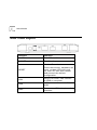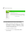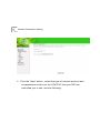
1
UTStarcom UT-300R2U
ADSL Modem
USER GUIDE
Release: 1.0
Doc. Code:
UTStarcom, Inc.
Copyright © 2005 UTStarcom, Inc. All rights reserved.
No part of this documentation may be reproduced in any form or by any means or
used to make any derivative work (such as translation, transformation, or
adaptation) without prior, express and written permission from UTStarcom, Inc.
UTStarcom, Inc. reserves the right to revise this documentation and to make
changes in content from time to time without obligation on the part of UTStarcom,
Inc. to provide notification of such revision or changes.
UTStarcom, Inc. provides this documentation without warranty of any kind, implied
or expressed, including but not limited to, the implied warranties of merchantability
and fitness for a particular purpose. UTStarcom may make improvements or
changes in the product(s) and/or the program(s) described in this documentation
at any time.
UNITED STATES GOVERNMENT LEGENDS:
If you are a United States government agency, then this documentation and the
software described herein are provided to you subject to the following:
United States Government Legend: All technical data and computer software is
commercial in nature and developed solely at private expense. Software is
delivered as Commercial Computer Software as defined in DFARS 252.227-7014
(June 1995) or as a commercial item as defined in FAR 2.101(a) and as such is
provided with only such rights as are provided in UTStarcom's standard
commercial license for the Software. Technical data is provided with limited rights
only as provided in DFAR 252.227-7015 (Nov 1995) or FAR 52.227-14 (June
1987), whichever is applicable. You agree not to remove or deface any portion of
any legend provided on any licensed program or documentation contained in, or
delivered to you in conjunction with, this User Guide.
UTStarcom, the UTStarcom logo, PAS, mSwitch, Airstar, WACOS, Netman, Total
Control, and CommWorks are registered trademarks of UTStarcom, Inc. and its
subsidiaries. The UTStarcom name, AN-2000, and the CommWorks logo are
trademarks of UTStarcom, Inc. and its subsidiaries.
Any rights not expressly granted herein are firmly reserved.
Contents
1
......................................................................................................... 1
Features ........................................................................................................ 1
Supporting Protocol ....................................................................................... 2
System Requirement ..................................................................................... 3
LED Indicator ................................................................................................. 4
Rear Pane Layout .......................................................................................... 5
2
......................................................................................................... 6
3
......................................................................................................... 8
Configuring Computer Network Card IP Address ........................................... 8
Web Setting Interface .................................................................................... 8
Ethernet over ATM (RFC1483 Bridge) Setting ............................................. 19
PPP over Ethernet (RFC2516) PPPoE Setting..............................................11
4
....................................................................................................... 23
5
....................................................................................................... 28
1
1
Introduction
This device is a well-designed high-speed ADSL modem/router.
Features
•
One 10/100 Ethernet port
•
One USB 1.1 Full Speed port
•
Friendly GUI for web configuration
•
Configurable as a DHCP Server on your Network
•
Compatible with virtually all standard Internet applications
•
Industry standard and interoperable DSL interface
•
Address Filtering, DMZ Hosting, and Much More
•
Simple web based status page displays a snapshot of your
system configuration, and links to the configuration pages.
•
Downloadable flash software upgrades
Introduction
•
Support for up to 8 Permanent Virtual Circuits (PVC)
•
Support for up to 8 PPPOE sessions
Supporting Protocol
•
ITU G.992.1 (G.dmt) Annex A
•
ITU G.992.2 (G.lite)
•
ANSI T1.413 Issue 2
•
ITU G.992.3 ADSL2 (G.dmt)
•
ITU G.992.4 ADSL2 (G.lite)
•
ITU G.992.5 ADSL2+
Encapsulation Supports:
•
RFC 1483 bridge
•
RFC 1483 Router
•
Classical IP over ATM (RFC 1577)
•
PPP over ATM (RFC 2364)
•
PPP over Ethernet (RFC 2516)
2
3
Introduction
System Requirement
Recommended system requirements are:
•
Pentium 233MHz or above
•
Memory: 64MB or above
•
10M Base-T Ethernet or above
•
WIN9X WIN2000 WINXP WINME WINNT
•
Ethernet Network Interface Card
Please collect the following information from your ADSL service
provider. This information will be very helpful for your ADSL
configuration. To keep a record for reference, you can fill in the
column as below:
VPI
VCI
Encapsulation: VCMUX or LLC
Protocol
Standard
Username
Password
Password protocol
Introduction
LED Indicator
Indicator
Status
Description
OFF
Power not supplied
ON
Power supply is on
ON
Have linked to HUB
Blink
Be transmitting data
to HUB
ON
Have connected to
CO physical layer
Slow Blink
Be trying to connect
to physical link
Quick Blink
Be handing with CO
physical link
Blink
Be receiving and
sending data
PWR
LAN
LINK
DATA
4
5
Introduction
Rear Pane Layout
Interface
Function
SWITCH
POWER on/off
POWER socket
PLUG in for power
Modem Reset button.
RESET
Press three times, hardware will
reset, modem LED will be all
on, then off, then auto-restart
and recover the default
configuration.
LAN
Plug in for RJ45, Can connect
to HUB or computer
USB
USB port can connect to PC
USB.
LINE
Connect to ADSL telephone line
interface
2
2
Hardware Installation
Please connect your ADSL MODEM to computer as the
following description:
•
If connecting to the splitter, connect the “Line” splitter to
wall jack using one telephone cable.
•
Use the other telephone cable to connect MODEM port of
the splitter and LINE port of the modem. The PHONE port
of the splitter can be used to connect the telephone and the
splitter by a telephone cable.
•
Use Ethernet cable to connect LAN port of the modem and
LAN port of your computer.
7
Hardware Installation
If do not need to connect to the splitter,
•
Connect the modem to wall jack using one telephone cable.
•
Use Ethernet cable to connect LAN port of the modem and
LAN port of your computer.
3
Modem Parameters Setting
Configuring Computer Network Card IP Address
Configuring your network card’s TCP/IP properties to obtain
an IP address automatically from modem, or set the
computer’s IP with the same network mask of the modem.
(For example: modem’s IP is 192.168.1.1/255.255.255.0,
then you can set computer’s IP to: 192.168.1.x/255.255.255.0,
the range for x is from 3 to 255)
Web Setting Interface
Open IE or Netscape Web browser,
Input http://192.168.1.1 (MODEM default IP address) in the
address column, then click <Enter> button, access the
following setting interface:
Input username and password, then click <Login> key to enter
WEB setting interface.
9
Modem Parameters Setting
Default setting:
IP Address: 192.168.1.1
Subnet Mask: 255.255.255.0
Username: admin
Password: utstar or admin
Main interface
When correct username and password have been typed, the
following window will pop up:
Modem Parameters Setting
10
Here provide the most common configuration for PPPoE and
Bridge mode for reference. The CPE shall be configured as
following (Advanced Setup – WAN) for MTNL network
11
Modem Parameters Setting
PPP over Ethernet (RFC2516) PPPoE Setting
PPPoE is also known as RFC 2516. It is a method of
encapsulating PPP packets over Ethernet. PPP or Point-toPoint protocol is a method of establishing a network
connection/session between network hosts. It usually provides
a mechanism of authenticating users.
To configure the MODEM for PPPoE:
1. From the Home page, click on “Advanced setup ->Wan ”,
see the following:
Modem Parameters Setting
12
Click on Edit button having VPI/VCI = 32, Check the following
options:
1.
VPI = 0
2.
VCI = 32
3.
Service category “UBR without PCR”
13
Modem Parameters Setting
2. Click the “Next” button , select the type of network protocol and
encapsulation mode over the ATM PVC that your ISP has
instructed you to use, see the following:
Modem Parameters Setting
3. Select PPP over Ethernet (PPPoE), Click the “Next” button.
14
Modem Parameters Setting
15
4. Type the username password given by the MTNL
5.
Type service name as MTNL . It is optional you can leave it as
blank also.
6.
Authentication method “AUTO”
7.
Click on next
Following window will come.
8. Enable IGMP Multicast, and enable WAN Service, see the
following.
Modem Parameters Setting
16
8. Click the “Next” button, configure the DSL Router IP Address
and Subnet Mask for LAN interface, please use the default
configurations, and see the following.
17
Modem Parameters Setting
9. Click the “Next” button; make sure that the settings below
match the settings provided by your ISP. See the following:
Modem Parameters Setting
10. Click on the “Save/Reboot” button, save your configurations,
and then finish the Setting for PPPoE.
18
19
Modem Parameters Setting
Ethernet over ATM (RFC1483 Bridge) Setting
From the Home page, click on “Advanced Setup ->Wan”, see
the following.
Click on Edit button having VPI/VCI = 0/33, Check the
following options:
4.
VPI = 0, VCI = 33
5.
Service category “UBR without PCR”
Click on next button
Modem Parameters Setting
1.
Click the “Next” button, and you can set the
encapsulation which get from your ADSL service
provider, see the following:
20
21
Modem Parameters Setting
2.
Click the “Next” button , select the check box below to
enable this WAN service, see the following:
Modem Parameters Setting
3.
22
Click the “Next” button, make sure that the settings below
match the settings provided by your ISP., see the following:
Click on the “Save/Reboot” button, save your configurations.
Note:
If you select Dial-UP link, after configuring your ADSL MODEM,
please install the third-party dial up program to access Internet
(For example: Ethernet 300/Ethernet 500/WinPoet). If your
system is WinXP, you can use its own Internet access program
without any other additional dialer.
4
USB Software Setup
Note:
The software setup process for all supported operating
systems is described in this section with operating system
specific differences noted. The USB ADSL Modem should be
connected to your PC prior to installing the software. No other
Windows programs should be running on your PC during the
software install process.
Before installing driver program, you must confirm ADSL
MODEM has been connected to computer via USB slot; Once
the PC powers up, a new device will be will be detected by
Windows .the computer will give a message finding new
hardware. Below picture will be shown
USB Software Setup
Just click next, new web will be shown below
24
25
USB Software Setup
Select “Search for a suitable driver
(recommended)”, then press next button
for
my
device
USB Software Setup
26
If you ADSL Modem USB driver is in CD-ROM, please select
CD –ROM driver, And If USB driver is other a location, please
select Specify a location. Then press next. Windows will
search and find the USB driver and automatically install the
driver.
27
USB Software Setup
Wait for a few seconds, below picture will display and you can
press the “Finish” button to complete the USB driver
installation.
When you have completed USB driver, Your PC will add new
adapter networks connect .It means you have success install
ADSL modem USB driver .You can configure your modem like
Ethernet, and connect internet. When you insert your driver
CD in your PC CD-ROM,
Questions & Answers
5
1.
Question: Why all LED indicators are off?
Answer:
•
Check the connection between the power adaptor and the
power socket.
•
Check the power switch is on or not.
2.
Question: Why ACT LED is not lighting?
Answer:
•
Check the connection between the ADSL modem and
your computer or Hub/Switch.
•
Check your PC or Hub/Switch running status and make
sure them are working normally.
•
Check your network cable for connecting the Modem with
other device:
For PC, you should use the crossover cable.
29
Questions & Answers
For Hub/Switch, you should use straight through cable.
3.
Question: Why Link LED is not lighting?
Answer:
Check the connection between the ADSL LINE port and the
wall jack.
4.
Question: Why cannot visit Internet with Link LED is
on?
Answer:
Make sure following information has been input correctly:
VPI/VCI
Username/password
5.
Question: Why cannot open the Modem configuration
web page?
Answer:
Follow below steps to check the communication between the
computer and Modem:
Questions & Answers
30
Click start -> run (input ping demands) -> Ping 192.168.1.1
(MODEM IP ADDRESS).
If cannot reach
configuration:
the
modem,
please
check
following
•
The type of the network cable
•
The connection between the modem and computer
•
Your computer’s TCP/IP setting
6.
Question: How to load the default setting after
incorrect configuration?
Answer:
Press Reset button and holds around 15s to load the default
configuration.
The modem’s default IP address: 192.168.1.1/255.255.255.0
Username/password:
admin/utstar.
UTStarcom, Inc. USA
1275 Harbor Bay Parkway Alameda, CA 94502, USA
Tel: 510-864-8800
http://www.utstar.com
Fax: 510-864-8802