1
User Guide
Matrix Switcher
SMX System
MultiMatrix Switcher
68-1452-01 Rev. C
04 13
Safety Instructions • English
WARNING: This symbol,
, when used on the product, is intended to
alert the user of the presence of uninsulated dangerous voltage within
the product’s enclosure that may present a risk of electric shock.
ATTENTION: This symbol,
, when used on the product, is intended
to alert the user of important operating and maintenance (servicing)
instructions in the literature provided with the equipment.
Chinese Simplified(简体中文)
警告:
产品上的这个标志意在警告用户该产品机壳内有暴露的危险
电压,有触电危险。
注 意:
产 品 上 的 这个 标 志 意 在 提 示用 户设 备 随 附 的 用 户手 册 中 有
重要的操作和维护(维修)说明。
关于我们产品的安全指南、遵循的规范、EMI/EMF 的兼容性、无障碍
For information on safety guidelines, regulatory compliances, EMI/EMF
compatibility, accessibility, and related topics, see the Extron Safety and
Regulatory Compliance Guide, part number 68-290-01, on the Extron
website, www.extron.com.
安全规范指南,产品编号 68-290-01。
Instructions de sécurité • Français
Chinese Traditional(繁體中文)
AVERTISSEMENT: Ce pictogramme,
, lorsqu’il est utilisé sur le
produit, signale à l’utilisateur la présence à l’intérieur du boîtier
du produit d’une tension électrique dangereuse susceptible de
provoquer un choc électrique.
ATTENTION: Ce pictogramme,
, lorsqu’il est utilisé sur le produit,
signale à l’utilisateur des instructions d’utilisation ou de maintenance
importantes qui se trouvent dans la documentation fournie avec le
matériel.
Pour en savoir plus sur les règles de sécurité, la conformité à la
réglementation, la compatibilité EMI/EMF, l’accessibilité, et autres sujets
connexes, lisez les informations de sécurité et de conformité Extron, réf. 68290-01, sur le site Extron, www.extron.fr.
使用的特性等相关内容,敬请访问 Extron 网站 www.extron.cn,参见 Extron
警告:
若產品上使用此符號,是為了提醒使用者,產品機殼內存在著
可能會導致觸電之風險的未絕緣危險電壓。
注意
若產品上使用此符號,是為了提醒使用者。
有關安全性指導方針、法規遵守、EMI/EMF 相容性、存取範圍和相關主題的詳細
資訊,請瀏覽 Extron 網站:www.extron.cn,然後參閱《Extron 安全性與法規
遵守手冊》,準則編號 68-290-01。
Japanese
警告: この記号
が製品上に表示されている場合は、筐体内に絶縁されて
いない高電圧が流れ、感電の危険があることを示しています。
Sicherheitsanweisungen • Deutsch
WARNUNG: Dieses Symbol
auf dem Produkt soll den Benutzer
darauf aufmerksam machen, dass im Inneren des Gehäuses dieses
Produktes gefährliche Spannungen herrschen, die nicht isoliert sind
und die einen elektrischen Schlag verursachen können.
VORSICHT: Dieses Symbol
auf dem Produkt soll dem Benutzer in
der im Lieferumfang enthaltenen Dokumentation besonders wichtige
Hinweise zur Bedienung und Wartung (Instandhaltung) geben.
Weitere Informationen über die Sicherheitsrichtlinien, Produkthandhabung,
EMI/EMF-Kompatibilität, Zugänglichkeit und verwandte Themen finden Sie
in den Extron-Richtlinien für Sicherheit und Handhabung (Artikelnummer 68290-01) auf der Extron-Website, www.extron.de.
Instrucciones de seguridad • Español
ADVERTENCIA: Este símbolo,
, cuando se utiliza en el producto,
avisa al usuario de la presencia de voltaje peligroso sin aislar dentro del
producto, lo que puede representar un riesgo de descarga eléctrica.
ATENCIÓN: Este símbolo,
, cuando se utiliza en el producto, avisa
al usuario de la presencia de importantes instrucciones de uso
y mantenimiento recogidas en la documentación proporcionada
con el equipo.
Para obtener información sobre directrices de seguridad, cumplimiento
de normativas, compatibilidad electromagnética, accesibilidad y temas
relacionados, consulte la Guía de cumplimiento de normativas y seguridad
de Extron, referencia 68-290-01, en el sitio Web de Extron, www.extron.es.
が製品上に表示されている場合は、本機の取扱説明書に
記載されている重要な操作と保守(整備)の指示についてユーザーの
注意を喚起するものです。
注意: この記号
安全上のご注意、法規厳守、EMI/EMF適合性、その他の関連項目に
ついては、エクストロンのウェブサイトwww.extron.jpより
『 Extron Safety and Regulatory Compliance Guide 』(P/N 68-290-01) をご覧ください。
Korean
경고: 이 기호
, 가 제품에 사용될 경우, 제품의 인클로저 내에 있는
접지되지 않은 위험한 전류로 인해 사용자가 감전될 위험이 있음을
경고합니다.
주의:
이 기호
, 가 제품에 사용될 경우, 장비와 함께 제공된 책자에 나와
있는 주요 운영 및 유지보수(정비) 지침을 경고합니다.
안전 가이드라인, 규제 준수, EMI/EMF 호환성, 접근성, 그리고 관련
항목에 대한 자세한 내용은 Extron 웹 사이트(www.extron.com)의
Extron 안전 및 규제 준수 안내서, 68-290-01 조항을 참조하십시오.
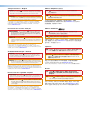
FCC Class A Notice
This equipment has been tested and found to comply with the limits for a Class A digital
device, pursuant to part 15 of the FCC rules. The Class A limits provide reasonable
protection against harmful interference when the equipment is operated in a commercial
environment. This equipment generates, uses, and can radiate radio frequency energy and,
if not installed and used in accordance with the instruction manual, may cause harmful
interference to radio communications. Operation of this equipment in a residential area is
likely to cause interference; the user must correct the interference at his own expense.
NOTE: This unit was tested with shielded I/O cables on the peripheral devices. Shielded
cables must be used to ensure compliance with FCC emissions limits.
For more information on safety guidelines, regulatory compliances, EMI/EMF
compatibility, accessibility, and related topics, see the “Extron Safety and
Regulatory Compliance Guide” on the Extron website.
Copyright
© 2013 Extron Electronics. All rights reserved.
Trademarks
All trademarks mentioned in this guide are the properties of their respective owners.
The following registered trademarks(R), registered service marks(SM), and trademarks(TM) are the property of
RGB Systems, Inc. or Extron Electronics:
Registered Trademarks (®)
AVTrac, Cable Cubby, CrossPoint, eBUS, EDID Manager, EDID Minder, Extron, Flat Field,GlobalViewer, Hideaway, Inline, IP Intercom, IP Link, Key Minder, LockIt, MediaLink, PoleVault,
PowerCage, PURE3, Quantum, SoundField, System Integrator, TouchLink, V-Lock, VersaTools, VN-Matrix, VoiceLift, WallVault, WindoWall
Registered Service Mark(SM) : S3 Service Support Solutions
Trademarks (™)
AAP, AFL (Accu-Rate Frame Lock), ADSP (Advanced Digital Sync Processing), AIS (Advanced Instruction Set), Auto-Image, CDRS (Class D Ripple Suppression), DDSP (Digital Display
Sync Processing), DMI (Dynamic Motion Interpolation), Driver Configurator, DSP Configurator, DSVP (Digital Sync Validation Processing), FastBite, FOXBOX, IP Intercom HelpDesk, MAAP,
MicroDigital, ProDSP, QS-FPC (QuickSwitch Front Panel Controller), Scope-Trigger, SIS, Simple Instruction Set, Skew-Free, SpeedMount, SpeedNav, SpeedSwitch, Triple-Action Switching,
XTP, XTP Systems, XTRA, ZipCaddy, ZipClip
Conventions Used in this Guide
Notifications
The following notifications are used in this guide:
CAUTION: A caution indicates a situation that may result in minor injury.
ATTENTION: Attention indicates a situation that may damage or destroy the product or
associated equipment.
NOTE: A note draws attention to important information.
TIP: A tip provides a suggestion to make working with the application easier.
Software Commands
Commands are written in the fonts shown here:
^AR Merge Scene,,Op1 scene 1,1 ^B 51 ^W^C
[01] R 0004 00300 00400 00800 00600 [02] 35 [17] [03]
E X! *X1&* X2)* X2#* X2! CE}
NOTE: For commands and examples of computer or device responses mentioned
in this guide, the character “0” is used for the number zero and “O” represents the
capital letter “o.”
Computer responses and directory paths that do not have variables are written in the font
shown here:
Reply from 208.132.180.48: bytes=32 times=2ms TTL=32
C:\Program Files\Extron
Variables are written in slanted form as shown here:
ping xxx.xxx.xxx.xxx —t
SOH R Data STX Command ETB ETX
Selectable items, such as menu names, menu options, buttons, tabs, and field names are
written in the font shown here:
From the File menu, select New.
Click the OK button.
Specifications Availability
Product specification are available on the Extron website, www.extron.com.
Contents
Introduction.................................................... 1
SMX Series Description....................................... 1
Definitions............................................................ 3
Features.............................................................. 4
Installation and Cabling................................ 6
UL Safety Requirements...................................... 6
Rear Panel Features and Connections................. 7
Power and Control Connections...................... 7
Input and Output Boards................................. 8
Other I/O Boards........................................... 10
SMX Frame and I/O Board Installation............... 10
Installing the I/O Boards................................. 10
Wiring the Audio Connectors............................. 12
Operation...................................................... 13
Front Panel Overview......................................... 13
I/O Plane Selection Buttons........................... 14
Input and Output Buttons.............................. 14
Control Buttons............................................. 15
Power Indicator LEDs.................................... 15
Front Panel Configuration Port....................... 16
Powering Up..................................................... 16
Front Panel Operation........................................ 16
Ties — General Information........................... 16
Creating Ties................................................. 17
Viewing Ties.................................................. 18
Removing Ties............................................... 19
Replacing Ties............................................... 20
Muting or Unmuting a Video, Audio,
or Video and Audio Output........................... 20
Saving and Recalling I/O Presets................... 22
Setting RGB Delay (VGA and RGBHV
Boards Only)................................................. 24
Setting the Front Panel Locks
(Executive Modes)........................................ 25
Setting Background Illuminations................... 26
Configuring Via the Rear Panel
RS232/RS422 Port.......................................... 27
Using the Front Panel.................................... 27
Viewing and Adjusting the Audio Input Level...... 27
Using the Front Panel.................................... 27
Viewing and Adjusting the Audio Output
Volume............................................................. 29
Using the Front Panel.................................... 29
Using Reset Levels............................................ 31
Using the Front Panel.................................... 31
Using the Rear Panel..................................... 31
Troubleshooting................................................. 33
SIS Configuration and Control................... 34
RS-232 or RS-422 Link..................................... 34
Ethernet (LAN) Port........................................... 34
Ethernet Cable............................................... 34
Default IP Addresses..................................... 34
Establishing an Ethernet Connection............. 35
Connection Timeouts.................................... 35
Number of Connections................................. 35
Using Verbose Mode..................................... 35
SIS Programming Guide.................................... 36
Host-to-SMX and SMX-to-Host
Communications.......................................... 36
Switcher-Initiated Messages.......................... 36
Switcher Error Responses............................. 37
Using the Command and Response Table
for SIS Commands........................................... 37
Symbol Definitions......................................... 38
Command and Response Table
for SIS Commands....................................... 42
Using the Command/Response Table
for IP SIS Commands....................................... 53
Symbol Definitions......................................... 53
Command and Response Table
for IP SIS Commands................................... 56
SMX System MultiMatrix Switcher • Contents
iv
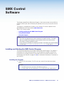
SMX Control Software................................. 59
Ethernet Control........................................ 106
Installing and Starting the SMX Control
Program........................................................... 59
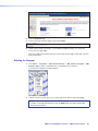
Installing the Program.................................... 59
Starting the Program..................................... 60
Using Emulation Mode...................................... 61
Using the Program............................................ 62
Control Program Menus and Pages............... 63
Customizing the SMX Window....................... 75
Managing Ties............................................... 76
IP Settings/Options........................................ 77
Ethernet Link................................................... 106
Ethernet Connection.................................... 106
Default Address........................................... 106
Configuring the SMX for Network
Communication.......................................... 107
Configuring the SMX for Network Use
Via the ARP Command............................... 108
Connect as a Telnet Client........................... 109
Subnetting — A Primer.................................... 111
Gateways.................................................... 111
Local and Remote Devices.......................... 111
IP Addresses and Octets............................. 111
Subnet Masks and Octets........................... 112
Determining Whether Devices Are
on the Same Subnet................................... 112
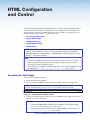
HTML Configuration and Control............... 87
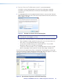
Accessing the Web Pages................................. 87
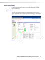
System Status Pages........................................ 89
System Status............................................... 89
Physical Configuration................................... 90
DSVP............................................................ 90
Configuration Pages.......................................... 91
System Settings Page................................... 91
Passwords Page........................................... 94
Email Settings Page....................................... 94
Firmware Upgrade Page................................ 96
File Management Page...................................... 97
Uploading Files.............................................. 98
Adding a Directory......................................... 98
Other File Management Activities................... 98
Control Pages................................................... 98
User Control Page......................................... 98
Presets Page............................................... 104
Reference Information.............................. 113
Mounting the Switcher..................................... 113
Tabletop Placement..................................... 113
UL Guidelines for Rack Mounted Devices.... 113
Rack Mounting............................................ 114
Button Labels.................................................. 114
Using the Button Label Generator................ 114
Replacing Button Labels.............................. 116
Button Label Blanks........................................ 117
SMX System MultiMatrix Switcher • Contents
v
Introduction
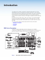
This guide contains installation, configuration, and operating information for the Extron
SMX MultiMatrix Switcher with optional input and output (I/O) boards. It covers operations
using the front panel controls and Simple Instruction Set (SIS™) commands. It also describes
how to load and start up the SMX Control Program that runs on Windows® operating
systems and how to connect to the built-in HTML pages for additional methods of operating
the SMX.
In this guide, the terms “SMX switcher,” “SMX,” and “switcher,” are used interchangeably
to refer to a typical SMX System MultiMatrix Switcher. “Video model” refers to any SMX
switcher that switches only video. “Audio model” refers to any SMX switcher that switches
only audio.
This section contains general information about the SMX switcher and includes:
•
SMX Series Description
•
Definitions
•
Features
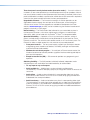
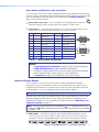
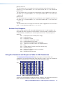
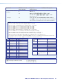
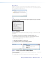
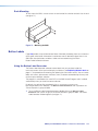
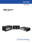
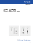
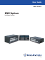
SMX Series Description
The SMX is a modular, configurable, multi-format card cage system, available in
2U (SMX 200), 3U (SMX 300), 4U (SMX 400), or 5U (SMX 500) frames. Each frame has rear
panel slots into which I/O boards can be inserted in any configuration and signal type.
FOX HDSDI
POWER
12V
0.3A MAX
OPTICAL
MODE
HD/SDI IN
1
1 2
Tx
2
BUFFERED OUTPUTS
Rx
Extron FOX HD-SDI
Transceiver
FOX HDSDI
POWER
12V
0.3A MAX
MODE
HD/SDI IN
OPTICAL
2
1
1
1 2
Tx
Rx
3
2
1
INPUTS
3
4
IN
IN
OUT
OUT
OUT
OUT
OUT
OUT
IN
IN
IN
OUT
IN
IN
OUT
OUT
IN
PLANE ADRESS
OUT
IN
IN
FIBER OPTIC
DIGITAL VIDEO
2
1
RESET
4
3
SDI / HDSDI INPUTS
COMPUTER IN
RS232/RS422
1
5
22
11
8
7
6
PLANE ADRESS
4
3
44
33
55
Data Monitors
4
3
2
8
77
66
SDI / HDSDI OUTPUTS
COMPUTER OUT
1
LINK
2
6
5
ACT
LAN
Compact HDTV
Camera Systems
OUT
OUT
IN
IN
4
3
2
1
FIBER OPTIC
REMOTE
OUTPUTS
PLANE ADRESS
4
3
3
2
2
1
1
Transceiver
HD Camera
4
2
BUFFERED OUTPUTS
Extron FOX HD-SDI
HD-SDI
Camera
Digital Monitors
HDTV Monitors
DVI Equipped PCs
2
1
2
1
8
7
4
3
5
S-VIDEO IN
2
1
Y
4
3
S-VIDEO
C
PCs
2
1
S-VIDEO IN
Y
2
1
8
7
4
3
S-VIDEO OUT
PLANE ADRESS
4
3
6
5
PLANE ADRESS
8
7
6
5
8
7
6
Video Recorders
4
3
C
S-VIDEO OUT
PLANE ADRESS
WB VIDEO
2
1
®
DVD/VCR Combo
4
3
L
1
R
L
2
L
R
3
L
R
5
VIDEO INPUTS
US
LISTED
IT23
I.T.E.
4
R
L
5
R
R
L
7
R
L
8
22
11
8
7
6
6
L
PLANE ADRESS
L
R
1
R
L
2
44
33
R
L
3
55
L
4
R
L
5
R
L
6
R
8
77
66
VIDEO OUTPUTS
R
L
7
R
L
8
Video Monitors
R
PLANE ADRESS
100-240V , 50-60Hz
2.0A MAX.
Extron
SMX System
DVD Player
Video Monitors
MultiMatrix Switcher
Sound Systems
TRANSITION
PROGRAM
FREEZE
1
2
3
4
5
6
LOGO 1
/BLACK
LOGO 2
/BLACK
CUT
PREVIEW
FREEZE
1
2
3
4
5
6
LOGO 1
/BLACK
LOGO 2
/BLACK
PICTURE
ADJUSTMENTS
TAKE
EFFECTS
WIPE
PIP
DISSOLVE
TITLE
ADJUST
BRIGHT
/CONT
DETAIL
CENTER COLOR
ZOOM
SIZE
/TINT
MENU
VOLUME
NEXT
ADJUST
CONFIG
ISS 506
Integration Seamless Switcher
Extron
ISS 506
Main Projection
Display
Figure 1.
Typical Matrix Swticher Application (5U Unit)
SMX System MultiMatrix Switcher • Introduction
1
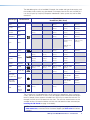
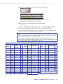
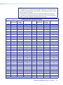
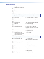
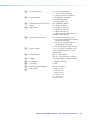
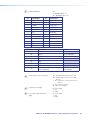
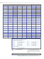
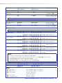
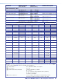
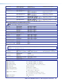
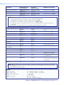
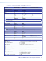
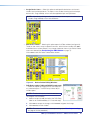
The table below gives a list of available I/O boards, the number and type of connectors, and
the number of slots used by any given board. For example, from the first row, the SMX 84 V
is an 8x4 (8 inputs by 4 outputs) composite video board. It takes up one slot, and has BNC
connectors.
Board Type
Board Names
I/O Connector
Board Sizes (Slots Used)
Composite
Video
BNC
SMX 84 V
8x4 (1)
SMX 88 V
8x8 (1)
SMX 1616 V
16x16 (2)
S-video
BNC
SMX 84 YC
8x4 (2)
SMX 88 YC
8x8 (2)
SMX 1616 YC
16x16 (4)
SDI and
HD-SDI
BNC
SMX 84 HD-SDI
8x4 (1)
SMX 88 HD-SDI
8x8 (1)
SMX 1616 HD-SDI
16x16 (2)
Ultra
Wideband
BNC
SMX 84 WB
8x4 (1)
SMX 88 WB
8x8 (1)
SMX 1616 WB
16x16 (2)
SMX 88
SYNC (H or V)
8x8 (1)
SMX 1616
SYNC (H or V)
16x16 (2)
Sync
SMX 44 HD-SDI
4x4 (1)
BNC
SMX 88 H+V
8x8 (2)
Stereo Audio
Captive
screw
L
DVI
DVI-Pro
DVI-I
(digital)
S-video
Boards
mini DIN
HDMI
HDMI
Wideband
VGA
15-pin HD
Fiber Optic
(singlemode)
Fiber Optic
(multimode)
USB
R
SMX 84 A
8x4 (1)
SMX 88 A
8x8 (1)
SMX 44 DVI
4x4 (1)
SMX 48 DVI
4x8 (2)
SMX 84 DVI
8x4 (2)
SMX 88 DVI
8x8 (2)
SMX 44
DVI Pro
4x4 (1)
SMX 48
DVI Pro
4x8 (2)
SMX 84
DVI Pro
8x4 (2)
SMX 88
DVI Pro
8x8 (2)
SMX 84 SV
8x4 (1)
SMX 88 SV
8x8 (1)
SMX 84 HDMI
8x4 (2)
SMX 88 HDMI
8x8 (2)
SMX 84 VGA
8x4 (2)
SMX 88 VGA
8x8 (2)
SMX 1616 VGA
16x16 (4)
SMX 88
FOX 4G SM
8x8 (1)
SMX 1616
4G SM
16x16 (2)
SMX 88
FOX 4G MM
8x8 (1)
SMX 1616
4G MM
16x16 (2)
SMX 44 HDMI
4x4 (1)
SMX 48 HDMI
4x8 (2)
Optical
(SFP)
USB B
input
SMX 1616 A
16x16 (2)
SMX 44 USB
4x4 (1)
SMX 1616 SV
16x16 (2)
SMX 84 USB
8x4 (1)
USB A
output
The 2U frame has 4 single board slots, the 3U frame has 6 board slots, the 4U frame has
8 slots, and the 5U frame has 10 slots. Each slot supports power and control connections
to the I/O boards. When a board is installed into a slot it may use more than one slot. For
example, the SMX 1616 VGA board uses four slots. The slots that a board covers are not
available for other I/O board installation until that multi-slot board has been removed (see
Installing the I/O Boards on page 10 for details).
NOTE: To customize the SMX unit, use the SMX Configurator program, available at
www.extron.com, or contact Extron Customer Support (see back cover for contact
numbers).
SMX System MultiMatrix Switcher • Introduction
2
Definitions
The following terms are used throughout this guide:
Tie — An input-to-output connection
Set of ties — An input tied to two or more outputs. An output can never be tied to more
than one input
Configuration — One or more ties or one or more sets of ties
Current configuration — The configuration that is currently active in the switcher (also
called configuration 0)
Plane — A board or set of boards that will be switched together. Plane numbers are set by
a rotary switch on each board.
Global memory preset — An I/O configuration that has been stored (all planes). Up to 32
global memory presets can be stored. Preset locations are assigned to the input buttons
and output buttons and can be selected from the front panel, serial port, or Ethernet control
for either saving or retrieving. When a preset is recalled from memory, it becomes the
current configuration.
Plane memory preset — A plane configuration that has been stored. Up to 10 plane
presets per switching plane can be saved and recalled without affecting the other I/O plane
connections.
EDID — Extended Display Identification Data. A communications protocol or instruction set
developed by VESA (Video Electronics Standards Association) for the identification of display
devices to computers using the DDC (Display Data Channel) transmission standard
HDCP — High-bandwidth Digital Content Protection. An encryption method developed
by Intel® that protects copyrighted digital entertainment material that uses the Digital Video
Interface (DVI) and High Definition Multimedia Interface (HDMI)
DVI — Digital Visual Interface. The digital video connectivity standard developed by DDWG
(Digital Display Work Group). This connection standard offers two different connectors:
one with 24 pins that handles digital video signals only, and one with 29 pins that handles
both digital and analog video. DVI standard uses TDMS (Transition Minimized Differential
Signal) from Silicon Image and DDC (Display Data Channel) from VESA (Video Electronics
Standards Association). DVI-D supports digital signal transfer only, and DVI-I supports both
digital and analog signal transfer.
HDMI® — High Definition Multimedia Interface. A specification developed by the HDMI
Working Group that combines video, multi-channel audio, and control signals into a single
digital interface for use with DVD players, digital television, and other audiovisual devices
SDI — Serial Digital Interface. This standard is based on a 270 Mbps transfer rate. It is a
10-bit, scrambled, polarity independent interface with common scrambling for both
component ITU-R 601 and composite digital video and four channels of embedded digital
audio.
HD-SDI — High-definition version of SDI specified in SMPTE-292M. This standard
transmits audio and video over a single coaxial cable with a data rate of 1.485 Gbit/second.
USB — Universal Serial Bus. Developed by PC and telecom industry leaders, USB was
designed for easy plug-and-play expansion outside the device, requiring no additional circuit
cards. USB devices can be attached or detached without removing computer power.
SMX System MultiMatrix Switcher • Introduction
3
Features
Hot swappable input/output boards and SFP modules — Any board or SFP module
can be added or replaced without taking the unit out of service or removing the power.
Channel to channel isolation — Each I/O board provides isolation between channels and
extremely low electrostatic emissions.
Quick-Switch Front Panel Controller (QS-FPC™) — The QuickSwitch FPC allows for
touch-of-a-button input and output selection and switching.
Presets — This time-saving feature allows the setup and recall of recurring I/O
configurations using either the front panel, RS-232 or RS-422, or Ethernet.
Global: Up to 32 individual I/O configurations may be saved and recalled.
Plane: Up to 10 presets per switching plane can be saved and recalled without
affecting the other I/O plane connections.
RS-232 and RS-422 control — A rear panel RS-232/RS-422 control port provides
connection to control software via a control system or PC.
Front panel control configuration port — A front panel 2.5 mm mini jack is available
for setup and configuration the SMX without having to access the rear of the unit while it is
installed within a rack system.
Simple Instruction Set (SIS) — The remote control protocol uses SIS commands for easy
programming and operation.
Control and configuration software — For RS-232, RS-422, and Ethernet control from
a PC, the Extron control software that runs on Windows operation systems is supplied with
every matrix switcher. This icon-driven software uses a graphical, drag-and-drop interface
to make input and output configuration and other customization functions simple and
convenient. The software also offers an emulation mode for configuration of an off-site
matrix switcher; the input and output configuration can then be saved for future
downloading to the SMX.
IP control (Ethernet) via the LAN port — This port allows the switcher to be controlled
through an Ethernet local area network (LAN) or wide area network (WAN) using standard IP
internet protocols. This ability provides flexible connectivity for off-site control and
password-protection of the switcher.
Web hosting — Users can upload customized web pages into the switcher.
Digital Sync Validation Processing (DSVP™) — In critical environments or unmanned,
remote locations, it may be vital to know that sources are active and switching. Extron
DSVP confirms that input sources are active by scanning all sync inputs for active signals.
DSVP provides instant frequency feedback for composite sync or separate horizontal
and vertical sync signals via the RS232/RS422 port or the Ethernet port.
Virtual plane grouping — Switching planes can be grouped together to make a single,
virtual switching plane. Plane grouping allows several signal planes to act as a single unit
with a single control command affecting all planes
Audio input gain and attenuation — Users can set the input level of audio gain or
attenuation (-18 dB to +24 dB) via the RS232/RS422 port, an Ethernet link, or the front
panel. Individual input audio levels can be adjusted so there are no noticeable volume
differences between sources.
Audio output volume (audio I/O boards) — The audio volume of each output can be
displayed and adjusted through a range from full output to completely silent using the front
panel, or through serial port or Ethernet control.
RGB delay (VGA and RGBHV) — This allows the delay of the output of the signal by a
specified time (the delay time), enabling video and audio signals to be kept in sync. RGB
delay can be set via the front panel, RS-232 or RS-422, or LAN connection.
SMX System MultiMatrix Switcher • Introduction
4
Three front panel security lockout modes (executive modes) — If a matrix switcher is
installed in an area where operation by unauthorized personnel may be a problem, either of
two security lockout modes can be implemented (the third mode is unlocked). When a front
panel locked mode is enabled, a special button combination or SIS command is required to
unlock the front panel controller and make the front panel operational.
Upgradeable firmware — The firmware that controls all switcher operation can be
upgraded on location through the serial port or the Ethernet port, without taking the
switcher out of service. Firmware upgrades are available for download on the Extron
website, www.extron.com, and they can be installed using the Windows-based control
program or the built-in HTML pages.
Button labeling — The Extron button label software lets you create labels to place in
the front panel I/O buttons, with names, alphanumeric characters, or color bitmaps.
Alternatively, labels can be made with any Brother® P-Touch® or comparable labeler.
Operational flexibility — Operations such as input and output selection, setting of
presets, and adjustment of audio levels can be performed on the front panel or via the
Ethernet or serial link. The serial links allow remote control via a PC or control system. The
Ethernet link allows multiple remote links with two levels of password-protection.
•
Front panel controls — The front panel controls support input and output selection
and grouping, preset creation and selection, RGB delay, audio gain and attenuation,
and volume control (audio models).
•
Windows-based control program — Via serial port or Ethernet remote control, the
Windows-based control software provides a graphical interface and drag-and-drop or
point-and-click operation.
•
Simple Instruction Set (SIS) — SIS commands provides easy programming and
operation.
Switching flexibility — The SMX provides individually buffered, independent matrix
switched outputs with audio follow and audio breakaway for audio models:
•
Tie any input to any or all outputs
•
Quick multiple tie — Multiple inputs can be switched to multiple outputs
simultaneously. This allows all displays (outputs) to change from source to source at the
same time.
•
Audio follow — Audio can be switched with its corresponding video input via front
panel control, under Ethernet, RS-232 or RS-422 control, or by giving the video and
audio boards the same plane address.
•
Audio breakaway — Audio can be broken away from its corresponding video signal.
This feature allows any audio signal to be selected with any video signal simultaneously
to one or all outputs in any combination. Audio breakaway switching can be done via
Ethernet, RS-232 or RS-422 control, or by giving the video and audio boards different
plane addresses.
SMX System MultiMatrix Switcher • Introduction
5
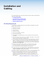
Installation and
Cabling
This section describes how to install the I/O boards and connect cables to the SMX device.
Topics in this section include:
•
UL Safety Requirements
•
Rear Panel Features and Connections
•
SMX Frame and I/O Board Installation
•
Wiring the Audio Connectors
UL Safety Requirements
The requirements listed below pertain to the safe installation and operation of this SMX.
Important safety instructions:
1. Read these instructions.
2. Keep these instructions.
3. Heed all warnings.
4. Follow all instructions.
5. Do not use this apparatus near water.
6. Clean only with a dry cloth.
7. Do not block any ventilation openings. Install in accordance with the manufacturer
instructions.
8. Do not install near any heat sources such as radiators, heat registers, stoves, or other
apparatus (including amplifiers) that produces heat.
9. Do not defeat the safety purpose of the polarized or grounding type plug. A polarized
plug has two blades with one wider than the other. A grounding type plug has two
blades and a third grounding prong. The wide blade or the third plug are provided for
your safety. If the provided plug does not fit into your outlet, consult an electrician for
replacement of the obsolete outlet.
10. Protect the power cord from being walked on or pinched particularly at plugs,
convenience receptacles, and the point where they exit from the apparatus.
11. Only use attachments/accessories specified by the manufacturer.
12. Use only with the cart, stand, tripod, bracket, or table specified by the manufacturer,
or sold with the apparatus. When a cart is used, use caution when moving the cart/
apparatus combination to avoid injury from tip-over.
13. Unplug this apparatus during lightning storms or when unused for long periods of time.
14. Refer all servicing to qualified service personnel. Servicing is required when the
apparatus has been damaged in any way, such as power-supply cord or plug is
damaged, liquid has been spilled or objects have fallen into the apparatus, the
apparatus has been exposed to rain or moisture, does not operate normally, or has
been dropped.
SMX System MultiMatrix Switcher • Installation and Cabling
6
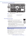
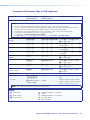
Rear Panel Features and Connections
2
1
3
4
1
OUT
IN
2
OUT
IN
OUT
3
IN
4
OUT
2
1
3
IN
6
OUT
IN
4
7
OUT
IN
5
8
OUT
IN
6
FIBER OPTIC
4
SDI / HDSDI INPUTS
5
8
7
6
22
11
ADDRESS
33
44
RESET
7
8
77
66
COMPUTER OUT
1
2
3
4
5
6
7
8
ACT LINK
55
SDI / HDSDI OUTPUTS
COMPUTER IN
RS232/RS422
LAN
3
DVI-D OUTPUTS
5
OUT
DIGITAL VIDEO
4
2
IN
ADDRESS
FIBER OPTIC
REMOTE
3
2
1
ADDRESS
DVI-D INPUTS
ADDRESS
1
2
3
4
5
6
7
8
8
S-VIDEO
2
1
3
4
5
6
7
4
1
2
3
S-VIDEO IN
8
2
1
ADDRESS
4
3
5
S-VIDEO OUT
9
8
7
6
S-VIDEO
2
1
3
4
S-VIDEO IN
2
1
10
4
3
S-VIDEO OUT
ADDRESS
VIDEO
2
1
1
L
1
R
L
2
R
4
VIDEO INPUTS
3
L
3
R
L
4
INPUTS
R
L
5
5
R
L
6
R
8
7
6
L
7
R
L
8
R
2
1
ADDRESS
L
1
R
VIDEO OUTPUTS
L
2
R
L
3
R
11
4
3
L
4
OUTPUTS
R
L
5
R
L
6
R
L
7
R
L
8
12
R
ADDRESS
100-240V , 50-60Hz
2.0A MAX.
13
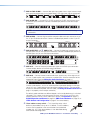
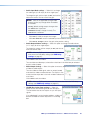
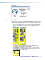
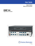
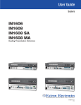
Figure 2.
SMX Rear Panel Features
a AC power connector
b LAN Ethernet port
c Reset button and LED
d Remote serial port
e to l I/O boards (optional)
m Plane address switch
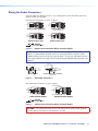
Power and Control Connections
LINK
LAN Ethernet port — Connect the switcher to an Ethernet LAN or
WAN via this RJ-45 connector. Ethernet connection allows the operator
to control the switcher from a remote location. When connected to an
Ethernet LAN or WAN, the switcher can be accessed and operated from a
computer running a standard Internet browser.
100-240V , 50-60Hz
2.0A MAX.
ACT
b
AC power connector — Plug a standard IEC power cord from a 100 to
240 VAC, 50 Hz or 60 Hz power source into this receptacle.
LAN
a
Ethernet connection indicators — The LEDs marked “Link” and “Act” indicate
the status of the Ethernet connection. The green Link LED lights when the SMX
is connected to an Ethernet LAN, and the amber Act LED flickers, indicating data
transmission as the devices communicate.
NOTE: Do not use standard telephone cables, as they do not support Ethernet or fast
Ethernet. Do not stretch or bend cables. Transmission errors can occur.
Choosing a network cable
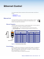
Ethernet links use Category (CAT) 3, 4, 5, 5e, 6, or CAT 7 unshielded twisted pair (UTP) or
shielded twisted pair (STP) cables, terminated with RJ-45 connectors. Ethernet cables are
limited to 328 feet (100 m).
The cable used depends on the network speed. The SMX supports both 10 Mbps
(10Base-T — Ethernet) and 100 Mbps (100Base-T — fast Ethernet), half-duplex and
full-duplex, Ethernet connections.
•
10Base-T Ethernet requires, at a minimum, CAT 3 UTP or STP cable.
•
100Base-T fast Ethernet requires, at minimum, CAT 5 UTP or STP cable.
SMX System MultiMatrix Switcher • Installation and Cabling
7
Reset button and Ethernet cable termination
RESET
It is essential that the Ethernet cables used be the correct type of cable and terminated with
the correct pinout. The cable can be terminated as either a patch cable or a crossover cable
and must be properly terminated relevant to the application (see Ethernet Control on
page 106 for termination details).
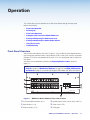
c
Reset button (recessed) — Press and hold in this recessed button to reset the
SMX to the default (factory setting) mode. The lit (green) LED blinks once.
d
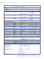
Remote port — Connect a host device, such as a PC or touchpanel control, to the
SMX via this 9-pin D connector for serial RS-232 or RS-422 control.
Pin RS-232
RS-232
Pin
——
11
22
TXTx
33
RXRx
44
——
5
Gnd
5
Gnd
6
—
76
——
87
——
8
9
——
9
Function
RS-422 Function
Function
Function
RS-422
Not used
used
Notused
used
—— Not
Not
Transmit
data
TXTx Transmit
Transmit data
Transmit data
data (-)(-)
Receive
data
Receive
data
RX
Receive data
Rx
Receive data (-)(-)
Not
used
Not
—
Not used
—
Notused
used
Signal ground Gnd
Signal ground
Signal ground
Gnd
Signal ground
Not used
Not used
—
Not used
—
Not used
Not
used
Receive
data (+)
RX+
Not
used
Rx+
Receive
Not used
Transmit data
data(+)(+)
TX+
Not
used
Tx+
Transmit
Not used
Not useddata (+)
—
—
Figure 3.
Not used
—
5
1
6
9
Female
1
5
6
9
Male
Not used
Remote Port Pin Assignments
NOTES:
• See SIS Configuration and Control on page 34 for SIS command definitions
or SMX Control Software on page 59 control software details.
• The SMX can support either RS-232 or RS-422 serial communication protocol,
and can operate at 9600, 19200, 38400, or 115200 baud rates
(see Operation on page 13 to configure the RS-232/RS-422 port).
Input and Output Boards
The I/O boards on any unit may vary with each installation, depending on desired
configuration and use. All board types have the input and the output connectors clearly
marked, and each board has a 16-position rotary switcher (see m, figure 2) for setting the
I/O plane address. An LED on the board indicates when power is present.
NOTE: Boards with the same plane address switch simultaneously.
Figure 2 shows some, but not all, board variations that can be installed into an SMX frame.
Boards have different combinations of input and output connectors, depending on the
specific board installed. To install any board into an SMX frame slot (see SMX Frame and
I/O Board Installation on page 10).
NOTE: Control signal ground pins may be labeled as or “G”. Audio ground pins may
be labeled as or . The wiring and function are the same, whichever way your product
is labeled.
e
SMX 44 DVI — Connect DVI single link high resolution digital input devices (up to
1600x1200 @ 60 Hz) or HDTV devices up to 1080p, to any of the DVI-I female input
connectors. Connect suitable digital displays to the DVI-I female output connectors.
1
2
3
DVI-D INPUTS
4
1
ADDRESS
2
3
4
DVI-D OUTPUTS
SMX System MultiMatrix Switcher • Installation and Cabling
8
f
SMX 44 FOX 4G MM — Connect fiber optic input cables from a signal source to input
ports and from output ports to a suitable display. LEDs light when signals are present.
1
OUT
IN
OUT
2
IN
3
OUT
IN
4
OUT
IN
FIBER OPTIC
g
5
OUT
IN
6
OUT
IN
ADDRESS
7
OUT
IN
8
OUT
IN
FIBER OPTIC
SMX 88 HD-SDI — Connect SDI, HD-SDI, or dual link HD-SDI input sources to any
of the BNC input connectors. Connect suitable display devices to the BNC output
connectors.
DIGITAL VIDEO
2
1
3
4
SDI / HDSDI INPUTS
5
8
7
6
22
11
ADDRESS
33
44
55
8
77
66
SDI / HDSDI OUTPUTS
NOTE: It is recommended to terminate unused I/Os with 75 ohm terminating
connectors.
h
SMX 88 VGA — Connect high resolution computer-video rate input sources to any of
the 15-pin HD female connectors. Connect suitable display devices to the 15-pin HD
output connectors.
COMPUTER IN
i
COMPUTER OUT
1
2
3
4
5
6
7
8
1
2
3
4
5
6
7
8
ADDRESS
SMX 88 SV (DIN) and j SMX 84 YC — Connect S-video input sources to any of
the BNC pairs or 4-pin mini DIN input connectors. Connect suitable display devices to
the BNC pairs or 4-pin mini DIN output connectors.
S-VIDEO
1
2
3
1
2
3
4
5
6
7
8
4
1
2
3
4
S-VIDEO IN
2
1
ADDRESS
4
3
5
S-VIDEO OUT
i
j
8
7
6
S-VIDEO
S-VIDEO IN
k
2
1
4
3
S-VIDEO OUT
ADDRESS
SMX 84 V — Connect composite video input signals to the BNC input connectors.
Connect display devices to the BNC output connectors.
VIDEO
2
1
l
4
VIDEO INPUTS
3
5
8
7
6
2
1
ADDRESS
VIDEO OUTPUTS
4
3
SMX 88 A — Connect stereo or mono audio input signals to any of the eight sets of
3.5 mm, 5-pole captive screw connectors marked Inputs. Wire the connector for the
appropriate signal type (see Wiring the Audio Connectors on page 12).
L
1
R
L
2
R
L
3
R
L
4
INPUTS
R
L
5
R
L
6
R
L
7
R
L
8
R
L
1
R
L
2
R
L
3
R
L
4
OUTPUTS
R
L
5
R
L
6
R
L
7
R
L
8
R
ADDRESS
Connect audio devices, such as an audio amplifier or powered speakers to the eight
sets of 3.5 mm, 5-pole captive screw connectors marked “Outputs.” The connectors
output the selected unamplified, line level audio (see Wiring the Audio Connectors on
page 12 to properly wire an output connector).
By default, audio and video use different boards, so that audio breakaway is switched
separately. This is done via the front panel, Ethernet, or the RS-232 or RS-422 link,
allowing selection from any of the audio input sources (see Operation on page 13,
SIS Configuration and Control on page 34, SMX Control Software on page 59, or
HTML Control and Configuration on page 87 for control details).
m
Plane address rotary switch — This 16 position rotary switch
defines a plane address for up to 16 I/O boards. To set an address,
insert a small screwdriver in the slot and rotate it to the desired
number (0-9, A-F). Each plane address is then identifiable during
SMX control and configuration.
SMX System MultiMatrix Switcher • Installation and Cabling
ADDRESS
9
Other I/O Boards
SMX 84 USB
Connect host devices (such as a PC) to any of the USB Type B Hosts ports (inputs).
Connect suitable USB devices (such as a mouse or keyboard) to any of the USB Type A
Device Hubs ports (outputs).
NOTES:
• There are 3 USB hubs in series within the USB boards. Per USB specifications, up to
5 USB hubs can be used in a system.
• USB boards cannot be cascaded.
• Appropriate USB Type A to USB Type B cables or adapters may be required for USB
Type B input signals.
HOSTS
1
2
3
4
DEVICE HUBS
1
5
6
7
8
ADDRESS
A
3
2
B
A
B
A
4
B
A
B
Features of SMX USB boards:
Peripheral emulation — Constantly emulates an HID (Human Interface Device) compliant
mouse and keyboard to any connected host without necessitating any ties to an output
device. This feature facilitates a problem-free boot up and is evident in the device manager
of the host PC as it constantly reports a mouse and keyboard are connected to it.
Host emulation — Emulates a host to multiple standard keyboards and mice. Connected
keyboards and mice operate as one unit.
The default setting for host emulation is Off. To enable or disable host emulation (see the
USB Board SIS commands on page 52 or USB Settings/Status on page 67).
NOTES:
• When host emulation is enabled, Device Hubs ports continually provide power to
attached peripherals. However, they will not function until ties are made to a host.
• Host emulation is valid through a hub or USB extender.
• If non-HID devices are connected to the Device Hubs ports, host emulation is
disabled.
Hot key switching — Routes or makes a tie between a specific input using a specific
combination of key presses on an attached keyboard and an output. To make a tie, press
<Ctrl> + <Shift> + <desired input to be tied>.
NOTES: Hot key switching can be executed only under the following conditions:
• Host emulation is enabled for the desired output.
• The output has a “standard” keyboard (it cannot require special USB drivers) to
execute the button combination for hot key switching.
KVM application — The USB and video board must be set to the same plane address in
order to switch the keyboard, video, and mouse together during ties.
SMX Frame and I/O Board Installation
If the SMX is to be rack mounted, it is important to mount it before cabling it (see Mounting
the Switcher on page 115).
Installing the I/O Boards
The I/O boards on any unit may vary with each installation, depending on desired
configuration and use. Each board has input and output connectors that are clearly marked,
and a 16-position rotary switch used to set the I/O plane address.
SMX System MultiMatrix Switcher • Installation and Cabling
10
NOTES:
• The boards are hot-swappable: they can be installed or removed without turning
off or disconnecting the power. However, turning the power off prior to installing or
removing boards is recommended.
• Use ESD precautions when installing a board to avoid damaging it. Keep the
board in the anti-static bag until needed. Use proper grounding techniques during
installation.
See Frames and I/O Boards on page 114 for a full list of available boards for the SMX.
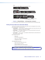
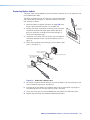
Installing new boards into an empty SMX frame
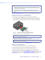
1. Remove as many of the blanks plates from the rear of the unit as needed.
2. When ready, remove the board from the anti-static bag, taking care not to touch any
of the components on the board. Slide the board into the open rear slot (see figure 4),
carefully aligning it with the plastic slides in the frame. Push the board firmly into place.
R OU
4
T
UTE
MP
CO
3
2
1
8
Y
7
16
6
15
5
C
14
13
12
ESS
E ADR
3
2
7
16
1
15
6
TE
MO
RESET
ACT LINK
LAN
tx
8
tx
EO
6
tx
7
4
3
8
7
2
TS
6
TPU
OU
5
11
tx rx
tx
4
5
10
9
E ADR
PLAN
16
15
12
tx rx
tx rx
2
3
O
OU
TS
14
4
1
13
SDI
3
SDI
UTS
INP
TPU
OU
/ HD
2
VID
ESS
E ADR
O
PLAN
VIDE
AL
DIGIT
4
10
9
tx rx
1
IDE
S-V
EO
VID
ESS
13
12
11
10
9
C
13
TS
TPU
12
11
C
14
5
Y
14
Y
8
RE
422
/RS
232
RS
15
10
9
UTE
MP
CO
16
11
PLAN
4
R IN
1
ESS
E ADR
PLAN
3
8
L
7
2
UTS
INP
L
6
5
1
4
SDI
3
US
®
L
UTS
INP
L
/ HD
L
2
D 17TTO
LISTE /VIDES
AUDIORATU
APPA
1.3A
Hz
40V
50-60
100-2
SDI
L
1
O
U
T
P
U
T
S
MAX.
L
L
L
L
L
L
L
IN
I
N
P
U
T
S
Figure 4.
1
R
9
R
2
10
12
5
R
L
13
6
R
L
14
7
L
15
8
R
R
R
L
R
L
L
11
4
R
R
L
L
L
3
16
R
I
N
P
U
T
S
R
R
R
R
R
L
1
9
10
3
12
5
R
L
13
6
R
L
14
7
L
15
8
R
R
R
L
R
L
L
11
4
R
R
L
L
L
2
R
R
16
R
O
U
T
P
U
T
S
R
R
R
R
R
ESS
E ADR
PLAN
Optional
Board
(audio shown)
SMX Frame Rear Showing Board Installation
3. Tighten down the screws on each end of the board.
NOTE: Use a tool to fully tighten the screws after initial installation and subsequent
removal and replacement of the boards.
4. Repeat steps 1 through 3 for all boards needing installation.
NOTE: If the unit is connected via RS-232 or RS-422, it responds with Reconfig
when a board is installed or replaced.
The SMX is now ready for cabling (see Input/Output Boards on page 8 for details).
Replacing an existing I/O board
1. Remove any input and output cables for the I/O board being replaced.
2. Loosen the outer screws on the existing board and remove it from the unit.
3. Slide the replacement board firmly into place and tighten down the screws.
4. Repeat for all boards to be replaced. Any new boards are now ready for cabling.
To configure the SMX with the new cards, see Operation on page 13. For alternative
configuration methods for the SMX, see SIS Configuration and Control on page 34, SMX
Control Software on page 59, and HTML Configuration and Control on page 87.
SMX System MultiMatrix Switcher • Installation and Cabling
11
Wiring the Audio Connectors
Connect audio input devices to the 3.5 mm, 5-pole captive screw connectors (up to two
groups of eight sets possible).
Wire the input connectors as shown in figure 5.
L
L
Tip
Ring
Sleeves
Tip
Ring
Tip
Ring
Sleeve
R
R
Balanced Audio Output Input
Balanced Mono Input
(high impedance)
L
L
Tip
Sleeve
Tip
Sleeve
Tip
Sleeve
R
R
Unbalanced Stereo Input
Unbalanced Mono Input
Do not tin the wires!
Figure 5.
Captive Screw Connector Wiring for Audio Signals
NOTE: When making connections for the SMX from existing audio cables (see
figure 7). A mono audio connector consists of the tip and sleeve, whereas a stereo
audio connector consists of the tip, ring, and sleeve. The tip, ring, and sleeve wires are
also shown above on the captive screw audio connector diagram (balanced inputs, see
figure 6).
Tip (+)
Ring (-)
Tip (+)
Sleeve ( )
Sleeve ( )
RCA Connector
Figure 6.
3.5 mm Stereo Plug Connector
(balanced)
RCA Audio Connectors
Wire the output connectors as show in figure 7.
No Ground Here
R
R
Tip
Sleeves
Tip
L
L
Tip
Ring
Sleeves
Tip
Ring
No Ground Here
Balanced Audio Output
Unbalanced Audio Output
Do not tin the wires!
Figure 7.
Captive Screw Connector Wiring for Audio Output
CAUTION: For unbalanced audio, connect the sleeves to the center contact ground.
Do not connect the sleeves to the negative (-) contacts.
SMX System MultiMatrix Switcher • Installation and Cabling
12
Operation
This section discusses the operation of an SMX series device through the front panel
buttons and includes:
•
Front Panel Overview
•
Powering Up
•
Front Panel Operation
•
Configuring the Rear Panel RS232/RS422 Port
•
Viewing and Adjusting the Audio Input Level
•
Viewing and Adjusting the Audio Output Volume
•
Using Reset Levels
•
Troubleshooting
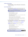
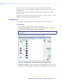
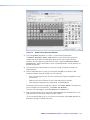
Front Panel Overview
SMX controls and indicators are shown in figure 8. They include I/O plane selection buttons,
input and output selection buttons, control buttons (Enter, Preset, View, and Esc) and power
indicator LEDs for the main board and I/O cards. A 2.5 mm configuration port is also on the
front panel.
All buttons can be relabelled as desired (see Replacing Buttons Labels section on
page 117).
NOTE: Some models have a blank front panel (no buttons) (see SIS Configuration and
Control on page 34, SMX Control Software on page 59, and HTML Configuration
and Control on page 87 to control and configure SMX models with blank front panels).
I/O PLANE SELECT
1
0 1 2 3 4 5 6 7 8 9 10 11 12 13 14 15
2
1 2 3 4 5 6 7 8 9 10 11 12 13 14 15 16
INPUTS
CONTROL
CONFIG
3
1 2 3 4 5 6 7 8 9 10 11 12 13 14 15 16
ENTER
PRESET
P
O
W
E
R
OUTPUTS
VIEW
ESC
MAIN
4
5
I/O CARDS
SMX SERIES SWITCHER
6
Figure 8.
SMX Series Matrix Switcher Front Panel Features
a I/O Plane Selection buttons (0-15)
b Inputs buttons (1-16)
c Outputs buttons (1-16)
d Control buttons (Enter, Preset, View, and Esc)
e Power status LEDs
f Config port
SMX System MultiMatrix Switcher • Operation
13
I/O Plane Selection Buttons
a
Plane selection buttons — The buttons, labeled 0 through 15, allow plane selection
and identify any tied inputs and outputs on the selected plane. These correspond to the
board rotary switch settings.
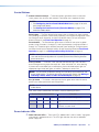
Input and Output Buttons
b
Input selection buttons — Input buttons 1 through 16 select inputs to tie to outputs,
remove or replace ties, and to view ties. Any input can be tied to any output as video,
audio, or both (see the Front Panel Operation on page 16 for more details).
NOTE: Input and output buttons light (or flash) green for video signals, red for audio
signals, and bright amber for both video and audio signals.
Input buttons are also used to:
c
•
Save and recall global presets (1 through 16)
•
Save and recall plane presets (1 though 10)
•
Display the output audio volume level
•
Display RGB delay up to 5 seconds (inputs 1-10), in 0.5 second intervals, (for SMX
VGA and RGBHV boards only)
•
Select inputs to view or adjust the audio level of that input
•
Select inputs to enable muting or unmuting of tied outputs
•
Set button backlight to On or Off (press and hold inputs 1 and 2 simultaneously)
•
Activate audio gain and output volume control (press any button twice, when the
SMX is in view mode with an audio plane selected).
Output selection buttons — The output buttons 1 through 16 select the output to tie
to any selected active input, and identify existing ties (video, audio, or both) active on
that selected output (see Front Panel Operation on page 16 and Viewing Ties on
page 18 for method).
Any output can be tied to any input as video, audio, or both (see Front Panel
Operation on page 16 and Creating Ties on page 17 for more details).
Output buttons are also used to:
•
Save and recall global presets (17 through 32, using outputs 1 though 16)
•
Display the input audio level
•
Show which outputs are tied to any selected input
•
Select outputs for muting or unmuting
•
Select an audio output for volume adjustment
•
Activate audio gain and output volume control (press any button once when an
audio plane is selected and flashing
NOTE: Throughout this guide, the front panel buttons status is
shown as unlit, lit, or flashing.
Unlit
Lit
Flashing
SMX System MultiMatrix Switcher • Operation
14
Control Buttons
d
Control selection buttons — These four buttons give direct access to the enter
(save), preset, view, and Esc (exit) controls. Each button has a separate function.
NOTES:
• See Configuring the Rear Panel RS232/RS422 Port on page 26 for serial
port configuration details.
• See Setting the Front Panel Locks (Executive Modes) on page 25 for
executive modes details.
Enter button — The Enter button flashes green when a change to an input or output
tie is pending, or red when a preset recall is pending. Pressing the flashing button saves
the change or recalls the preset, and the Enter button and any lit input and output
buttons extinguish (see Front Panel Operation on page 16).
Preset button — The Preset button gives access to recall or save up to 32 global
presets (using I/O buttons 1 through 16), and 10 plane presets (using input buttons 1
through 10). The button lights red when pressed. Upon recalling or saving the preset,
the button and all input and output buttons (lit red) are extinguished (see Front Panel
Operation on page 16 and Saving and Recalling I/O Presets on page 22).
NOTE: Global presets save and recall the configuration for all planes. Plane presets
save and recall the configurations for a specific plane without affecting the other
plane connections.
View (<) button — This button, when pressed and released, lights red and allows
quick viewing of existing input and output ties. When the button is lit, after selecting
a plane and an associated input, muted outputs flash and untied outputs light the
appropriate signal color (red, green, or amber). Tied outputs remain unlit.
NOTE: Use this button to decrease settings for RGB delay, input audio level, and
output audio volume. This button also mutes and unmutes outputs (see Muting or
Unmuting a Video, Audio, or Video and Audio Output on page 20).
Esc (>) button — This button, when pressed, flashes green once and all lit control,
plane, input, and output buttons are extinguished.
NOTE: Use this button to increase the RGB delay, input audio level, and output
audio volume.
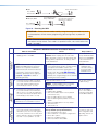
Also, when used in combination, the buttons have the following functions:
Control Button Combination
Enter
Function
Preset
View
Esc
Selects the serial port configuration.
Preset
View
Esc
Toggles between executive modes 2x and 0x.
View
Esc
Toggles between executive modes 2x and 1x
or initiates a system reset.
Power Indicator LEDs
e
Power indicator LEDs — These two LEDs, labeled “Main” and “I/O Cards,” light green
when power is applied to the unit. The LEDs light red when the main or redundant
power supply fails.
SMX System MultiMatrix Switcher • Operation
15
Front Panel Configuration Port
f
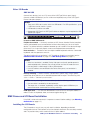
Configuration port — This 2.5 mm port (jack) can be used to configure the SMX
during setup via RS-232, and has an independent protocol from the primary RS-232
port on the rear panel. Use the 2.5 mm configuration cable, part number 70-335-01
(see figure 9) for connection to your PC serial port.
RS-232 protocol (default): 9600 baud, 1 stop bit, no parity, 8 data bits, no flow control.
6 feet
1
6
9
5
Tip
Ring
Sleeve (Gnd)
9-pin D
Connection
TRS Plug
Pin 2
Computer Rx line
Tip
Pin 3
Computer Tx line
Ring
Pin 5
Computer signal ground
Sleeve
Figure 9.
Front Panel 2.5 mm Port Configuration Cable
NOTE: This port does not support RS-422.
Powering Up
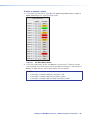
When power is applied to the SMX, it undergoes a start-up self testing sequence:
1. All buttons flash green, red, and then amber, before extinguishing.
NOTE: The order in which the colors are displayed may vary.
2. The two LEDs light green to indicate power is present to the main unit and I/O boards.
NOTE: This sequence also occurs when the unit restarts after firmware uploads.
Front Panel Operation
This section covers basic setup and configuration of the SMX using the front panel.
Ties — General Information
•
During any operation of front panel buttons, any active input, output, and control
buttons stay lit or blink for 30 seconds. If, during that 30 seconds, no button is pressed,
a time-out occurs and all buttons go out. The operation must be restarted.
•
To enable any selected input signal to be viewed on a display device, the input must be
tied to an output on the same plane.
•
An output can be tied to one input only, but an input can have multiple outputs.
•
If an input with no existing tie is selected, only that input button lights when pressed. No
output buttons light.
•
When a plane and an input are selected, the associated output buttons flash the
appropriate color to indicate tentative ties. Buttons for outputs to the selected input light
steadily in the appropriate color.
•
If a tie is made between an input and an output and the selected output was previously
tied to another input, the older tie is broken when the Enter button is pressed.
SMX System MultiMatrix Switcher • Operation
16
•
If any associated (lit) output button (an existing tie) is toggled off by pressing the button
and the Enter button is pressed, the existing tie to that output is lost.
•
Ties can be made using SIS commands via RS-232, RS-422, Ethernet, the SMX
Control Software program, or the internal Web pages (see SIS Configuration and
Control on page 34 for RS-232 and RS-422 control, SMX Control Software on
page 59 for Software, or HTML Configuration and Control on page 87 for HTTP
methods).
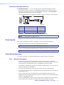
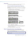
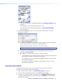
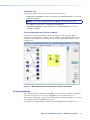
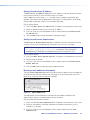
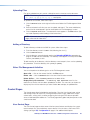
Creating Ties
To make input ties to untied outputs:
An example of creating an input to output tie
The following shows how to create a tie (input 7 on plane 0 to output 4 in this example).
1. Press and release the Esc button to clear any pending input, output, or control button
changes. The Esc button flashes green once.
2. Press and release the I/O Plane Select button for the desired configuration.
NOTE: The I/O Plane button and Input button 1 lights, indicating the signal type:
green for video, red for audio, or amber for both video and audio signals. In the
examples below, the plane carries a video signal only.
Step 2.
Press and release the desired I/O Plane Select button.
I/O PLANE SELECT
0 1 2 3 4 5 6 7 8 9 10 11 12 13 14 15
Step
2. and Input buttons light green if on a video plane, red if on
I/O plane
an audio
plane,
or amber
if on a video
and audio
plane.
Press
and
release
the desired
I/O Plane
Select
button.
I/O PLANE SELECT
Step 3.
Press
2 3 Input
4 5button
6 7(lights).
8 9 10 11 12 13 14 15
0 1desired
I/O plane and Input buttons lightINPUTS
green if on a video plane, red if on
an1audio
amber
and11
audio
2 plane,
9 10
13 14 15 16
3 4 or 5
6 if7on 8a video
12 plane.
Step 3.
1 2 3 4 5 6 7 8 9 10 11 12 13 14 15 16
Press desired Input button (lights).
OUTPUTS
INPUTS
Currently tied outputs light according to the signal type of the output.
1 12extinguishes.
3 4 5 6 7 8 9 10 11 12 13 14 15 16
Input
5.
Figure
Select
an Example
(Steps 2 and 3)
1 2 310.
9 10 11then
4 5
6 7 I/O
8 Plane,
12 13an
14Input
15 16 — Step
Press and release Enter.
OUTPUTS
INPUTS
3. Press
release
the
desired
input
(see
figure 10).CThis
lights according
O N T Rbutton
OL
Currentlyand
tied outputs
light
according
to the
signalbutton
type of the
output.
1the
9 10 (video),
14 (audio),
15 16 or amber (both).
3 4 signal
7 8 green
11 12 13red
5 6 type:
Input
12 extinguishes.
to
plane
1 2 3 4 5 6 7 8 9 10 11 12 13 14 15 16
OUTPUTS
ENTER PRESET
VIEW
ESC
Step 5.
Press and release Enter.
INPUTS
Step 4.
1 2and3 release
9 10 11
4 5 the
14 15 16
6 desired
7 8 output
12 13
Press
button
(flashes).
The Enter button also flashes (green).
1 2 3 4 5 6 7 8 9 10 11 12 13 14 15 16
C Oextinguish.
NTROL
All buttons
ENTER PRESET
VIEW
ESC
OUTPUTS
Step 4.
Press and release the desired output button (flashes).
All buttons extinguish.
The Enter button also flashes (green).
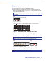
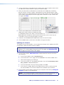
Figure 11. Select the Outputs, then Press Enter — an Example (Steps 4 and 5)
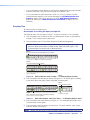
4. Press and release the output buttons (see figure 11). The selected output buttons flash.
The enter button flashes green.
5. Press and release the Enter button to make the tie. The plane selection, input, output,
and Enter buttons all extinguish.
NOTE: Repeat steps 2 through 5 if the Enter button extinguishes before being pressed.
SMX System MultiMatrix Switcher • Operation
17
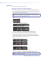
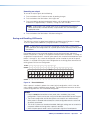
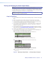
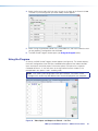
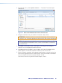
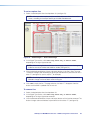
Viewing Ties
Any existing input to output tie can be viewed.
An example of viewing a set of video or audio ties
The following shows how to view existing ties on any allocated plane (here planes 0 and 2).
1. Press and release the View button (lights red). The last plane button used (here 0) lights
green, and untied output buttons light the appropriate color for the plane signal type,
(green for video, red for audio, amber for both).
NOTE: If all output buttons light, no outputs are tied. If no output buttons light, all
outputs are tied. The maximum number of buttons that may light corresponds to
the number of outputs on the plane card (4, 8, or 16).
Step 1.
Press the View button (lights red).
CONTROL
ENTER PRESET
VIEW
ESC
The last plane button used lights green (if a video plane),
red (if an audio plane), or amber (if a video and audio plane).
I/O PLANE SELECT
0 1 2 3 4 5 6 7 8 9 10 11 12 13 14 15
Untied buttons (Outputs 1, 2, 6, 7, and 12 through 16) light
green, red, or amber. No input buttons light.
INPUTS
1 2 3 4 5 6 7 8 9 10 11 12 13 14 15 16
1 2 3 4 5 6 7 8 9 10 11 12 13 14 15 16
OUTPUTS
Figure 12. Viewing Ties — an Example of Untied Outputs (Step 1)
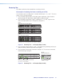
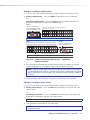
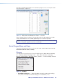
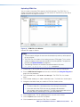
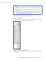
2. Press and release another plane selection button to view ties for that plane.
3. To view the input tied to it, press any of the unlit output buttons (in the example
below, buttons 10 through 12, and 16). The untied output buttons extinguish, and the
previously tied output buttons (10 through 12 and 16) and the associated tied input
button (3) light the appropriate color (see figure 13).
Step 2.
Press plane button 3 (lights red - audio plane).
I/O PLANE SELECT
0 1 2 3 4 5 6 7 8 9 10 11 12 13 14 15
Untied output buttons light, indicating signal type: red (audio).
INPUTS
1 2 3 4 5 6 7 8 9 10 11 12 13 14 15 16
1 2 3 4 5 6 7 8 9 10 11 12 13 14 15 16
OUTPUTS
Step 3.
Press a tied output button (10).
INPUTS
1 2 3 4 5 6 7 8 9 10 11 12 13 14 15 16
1 2 3 4 5 6 7 8 9 10 11 12 13 14 15 16
OUTPUTS
Tied outputs (10 through 12, and 16) and associated input (3) light the same color.
Figure 13. Viewing Ties — an Example of Tied Outputs (Steps 2 and 3)
NOTE: To clear the lights after viewing, press and release the Esc button. This does
not clear or change any existing ties.
SMX System MultiMatrix Switcher • Operation
18
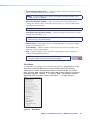
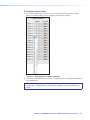
Removing Ties
Any video or audio tie can be removed from an existing set of ties.
An example of removing ties from an existing set of ties
In this example, input 3 on video plane 0 is already tied to outputs 2, 4, 6, and 7. The ties to
outputs 4 and 7 are to be removed.
1. Press and release plane button 0 which lights green. Input button 1 lights the plane
signal type: green for video, red for audio, amber for video and audio.
2. Press and release input button 3 (lights). Tied outputs (2, 4, 6, and 7) light the same
color as the input button. Input 1 extinguishes (see figure 14).
Step 1.
Press plane button 0 (lights green).
I/O PLANE SELECT
0 1 2 3 4 5 6 7 8 9 10 11 12 13 14 15
Input button 1 lights, indicating signal type: green (video) or red (audio).
INPUTS
1 2 3 4 5 6 7 8 9 10 11 12 13 14 15 16
1 2 3 4 5 6 7 8 9 10 11 12 13 14 15 16
OUTPUTS
Step 2.
Press Input 3 button (lights).
INPUTS
1 2 3 4 5 6 7 8 9 10 11 12 13 14 15 16
1 2 3 4 5 6 7 8 9 10 11 12 13 14 15 16
OUTPUTS
Tied outputs (2, 4, 6, and 7) light same color, and Input 1 extinguishes.
Figure 14. Removing Ties — an Example (Steps 1 and 2)
3. Press and release outputs buttons 4 and 7. They begin flashing (indicating that they are
ready for removal), and the Enter button flashes green.
4. Press and release the flashing Enter button (see figure 15). The two ties are removed,
and all button lights extinguish.
INPUTS
1 2 3 4 5 6 7 8 9 10 11 12 13 14 15 16
1 2 3 4 5 6 7 8 9 10 11 12 13 14 15 16
Step 4.
Press and release the
Enter button to remove ties.
CONTROL
ENTER PRESET
VIEW
ESC
OUTPUTS
Step 3.
Press and release Output 4 and 7 (flashes).
Enter button also blinks (green).
All buttons extinguish.
Figure 15. Removing Ties — an Example (Steps 3 and 4)
SMX System MultiMatrix Switcher • Operation
19
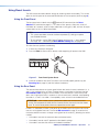
Replacing Ties
An input tied to an output can be replaced with another input, as long as that input is of a
similar type or plane (for example, video for video and audio for audio).
An example of replacing an existing tied input with another input
In the following example, input 2 on video plane 0 is tied to output 1, 4, and 8. The input 2
signal to output 1 is to be replaced by the input 7 signal, also on plane 0, and already tied to
outputs 3 and 6.
1. Press and release plane button 0. It lights green. Input button 1 lights, indicating plane
signal type (green for video, red for audio, amber for both).
2. Press and release input button 7, which lights. Tied output buttons (3 and 6 in this
example) light the same color as the input button. The input 1 button extinguishes.
Input 2 is tied to outputs 1, 4, and 8 (all lit).
INPUTS
1 2 3 4 5 6 7 8 9 10 11 12 13 14 15 16
1 2 3 4 5 6 7 8 9 10 11 12 13 14 15 16
OUTPUTS
Step 1.
Press and release the I/O Plane 0 button. It lights green.
I/O PLANE SELECT
0 1 2 3 4 5 6 7 8 9 10 11 12 13 14 15
Input button 1 lights green (video plane), red (audio plane), or amber (video and audio plane).
Step 2.
Press Input button 7 (lights).
INPUTS
1 2 3 4 5 6 7 8 9 10 11 12 13 14 15 16
1 2 3 4 5 6 7 8 9 10 11 12 13 14 15 16
OUTPUTS
Outputs 3 and 6 light the same color as the input 7 button. Input 1 extinguishes.
INPUTS
1 2 3 4 5 6 7 8 9 10 11 12 13 14 15 16
1 2 3 4 5 6 7 8 9 10 11 12 13 14 15 16
Step 4.
Press and release Enter.
CONTROL
ENTER PRESET
VIEW
ESC
OUTPUTS
Step 3.
Press and release Output 1 button (flashes). Enter blinks (green).
All buttons extinguish.
Figure 16. Replacing Ties — an Example
3. Press and release the output 1 button. This button flashes the same color as the input
button, and the Enter button flashes green. The other tied buttons (3 and 6 in this
example) remain lit (see figure 16).
4. Press and release the Enter button. All button lights extinguish.
Muting or Unmuting a Video, Audio, or Video and Audio Output
Any output signal can be muted or unmuted (see the Note below). Muted signals are
indicated by a flashing output button when in View mode and with the selected plane
buttons lit. The tie for the muted signal still exists.
NOTE: When the front panel is in lock mode 2, the output mute status can be viewed
only and no changes to the mute status (muting or unmuting a signal) can be made
from the front panel.
SMX System MultiMatrix Switcher • Operation
20
Muting an output
To mute an output signal, do the following:
1. Press and release the Esc button to clear all pending changes.
2. Press and release the View button, which lights red. The previously selected plane
button and untied output buttons light (see figure 17), or flash if the outputs are already
muted. Tied outputs remain unlit.
NOTE: For video signals, output buttons light or flash green; for audio only signals,
the buttons light or flash red, and for video and audio signals, the buttons light or
flash amber.
Step 2.
Press and release the View button (lights red).
CONTROL
ENTER PRESET
VIEW
ESC
The last plane button used lights.
Step 3.
Press and release the desired I/O Plane (here plane 2).
The plane button and any untied outputs light. Muted outputs flash. Tied outputs remain unlit.
I/O PLANE SELECT
0 1 2 3 4 5 6 7 8 9 10 11 12 13 14 15
INPUTS
1 2 3 4 5 6 7 8 9 10 11 12 13 14 15 16
1 2 3 4 5 6 7 8 9 10 11 12 13 14 15 16
OUTPUTS
Figure 17. Muting Output Signals — an Example (Steps 2 and 3)
3. Select the applicable plane which lights. The output buttons light if they are untied or
flash if they are tied and muted in the signal type color. Tied outputs remain unlit.
4. Press and hold the desired output button for 2 seconds or until the button flashes, then
release. The signal is now muted (see figure 18).
NOTE: If the button flashes red, the audio signal is muted. If the button flashes
green, the video signal is muted. If it flashes amber, both are muted.
Step 4.
Press and hold the desired output buttons for 2 seconds.
INPUTS
Step 5.
Press and release the
View button.
1 2 3 4 5 6 7 8 9 10 11 12 13 14 15 16
1 2 3 4 5 6 7 8 9 10 11 12 13 14 15 16
CONTROL
ENTER PRESET
VIEW
ESC
OUTPUTS
Each selected button flashes (green, red, or amber).
All buttons extinguish.
Figure 18. Muting Output Signals — an Example (Steps 4 and 5)
5. Press and release the View button. All buttons extinguish.
NOTE: For video, only RGB is muted. Sync is not muted.
SMX System MultiMatrix Switcher • Operation
21
Unmuting an output
To unmute an output signal, do the following:
1. Press and release the Esc button to clear all pending changes.
2. Press and release the View button, which lights red.
3. Press and hold the desired muted output button, until the button light ceases to flash
and remains lit (approximately 2 seconds). The signal is now unmuted.
NOTE: Output buttons with muted signals flash the appropriate color (green for
video, red for audio, or amber for both). Output buttons with unmuted signals
appropriate color.
4. Press and release the View button. All buttons extinguish.
Saving and Recalling I/O Presets
The SMX has a total of 32 global preset addresses available (using I/O buttons 1 through
16) and 10 plane preset addresses (using Input buttons 1 through 10).
NOTE: A global preset saves and recalls configurations for all planes. A plane preset
saves and recalls the configurations for a specific plane without affecting the other plane
connections.
Each global preset can be saved and recalled using the front panel input and output
buttons, with presets 1 through 16 assigned to the input buttons and presets 17 through 32
assigned to the output buttons. Likewise, plane presets are saved to and recalled from input
buttons 1 through 10. Any current tie configuration can be saved to any one of the preset
locations, in any order. Saving the current configuration to an existing preset overwrites the
existing preset with the new configuration.
PLANE
GLOBAL
Preset Preset Preset Preset Preset Preset Preset Preset Preset Preset
1
2
3
4
5
6
7
8
9
10
Preset Preset Preset Preset Preset Preset Preset Preset Preset Preset Preset Preset Preset Preset Preset Preset
1
2
3
4
5
6
7
8
9
10
11
12
13
14
15
16
INPUTS
1
2
3
4
5
6
7
1
2
3
4
5
6
7
8
9 10 11 12 13 14 15 16
8
9 10 11 12 13 14 15 16
OUTPUTS
GLOBAL Preset
17
Preset Preset Preset Preset Preset Preset Preset Preset Preset Preset Preset Preset Preset Preset Preset
18
19
20
21
22
23
24
25
26
27
28
29
30
31
32
Figure 19. Preset Addresses
When a preset is recalled, it replaces the current (active) configuration, which is then lost
unless already saved to a different preset location. The recalled preset overwrites all of the
current configuration ties with the recalled configuration.
NOTES:
• Presets cannot be viewed from a front panel unless recalled as the current
configuration. Presets can be seen using the Windows based SMX Control Program.
• The current configuration and all other presets are stored in non-volatile memory.
When power is removed and restored, the current configuration remains active and
all presets are retained.
• Ties for all I/O planes are stored and recalled. Audio gain settings are not saved with
the preset and do not change when a preset is recalled.
• When the plane preset mode is active, input buttons light for all saved presets.
SMX System MultiMatrix Switcher • Operation
22
Saving or recalling a global preset
1. Press the Esc button to clear all pending changes. The button flashes green once.
2. Saving a global preset — Press and hold the Preset button until it flashes red.
OR
Recalling a global preset — Press and release the Preset button (lights red). All
previously saved presets also light red. Proceed to step 4.
Step 2.
To save a global preset,
press and hold the Preset
button until it flashes red.
Buttons for any previously saved presets light red
(here preset 8, 18, and 32).
INPUTS
1 2 3 4 5 6 7 8 9 10 11 12 13 14 15 16
CONTROL
ENTER PRESET
VIEW
1 2 3 4 5 6 7 8 9 10 11 12 13 14 15 16
ESC
OUTPUTS
NOTE: To recall a global preset, press and release the Preset button (lights red).
Step 3.
Press and release the desired (unlit or lit) input or output
button (here output 5, preset 21). The button flashes red.
Step 4.
Press the Enter button to
save or recall preset.
INPUTS
CONTROL
1 2 3 4 5 6 7 8 9 10 11 12 13 14 15 16
1 2 3 4 5 6 7 8 9 10 11 12 13 14 15 16
ENTER PRESET
VIEW
ESC
OUTPUTS
Enter button also blinks (red).
All buttons extinguish.
NOTE: To recall a global preset, press and release a lit Preset button.
Figure 20. Saving or Recalling a Global Preset — An Example
(Steps 2 through 4)
3. Press and release a desired input or output button to select the address to save the
current configuration to. The Address, Preset, and Enter buttons flash red.
NOTE: A preset can be saved to any lit or unlit button. Only presets with lit buttons
can be recalled. When a preset is saved to a lit (previously saved button, the stored
data is overwritten with the new data. Only one preset can be saved to an address
at a time.
4. Press and release the Enter button. The preset is saved or recalled as specified.
Saving or recalling a plane preset
1. Press the Esc button to clear all pending changes. The button flashes green once.
2. Saving a plane preset — Press and hold the Preset button until it flashes red, then
select a plane.
OR
Recalling a plane preset — Press and release the Preset button , which lights red.
All previously saved presets light red, then select a plane.
NOTE: Lit presets are global presets, not plane presets.
3. Press and release a plane button. The button lights.
NOTE: The lit buttons for global presets extinguish, and the buttons for any saved
plane presets light.
SMX System MultiMatrix Switcher • Operation
23
4. Press and release the desired input button (1-10) to select a plane preset address.
Saving a plane preset — The Address, Preset, and Enter buttons flash crimson.
Recalling a plane preset — The Address and Enter buttons flash crimson.
NOTE: A preset can be saved to any lit or unlit input button (1 through 10). Only
presets with lit buttons can be recalled. When a preset is saved to a lit button
(already containing a preset), the stored data is overwritten with the new data. Only
one plane preset can be saved to an address at a time.
5. Press and release the Enter button. The plane preset is saved or recalled.
Step 3.
Press desired plane button (here plane 0).
I/O PLANE SELECT
0 1 2 3 4 5 6 7 8 9 10 11 12 13 14 15
Plane button lights green.
Buttons for any previously saved plane presets light red (here preset 7).
Step 4.
Press and release the desired (unlit or lit) input button 1-10
(here preset 3). The selected button flashes red.
Step 5.
Press the Enter button to
save or recall the preset.
INPUTS
1 2 3 4 5 6 7 8 9 10 11 12 13 14 15 16
1 2 3 4 5 6 7 8 9 10 11 12 13 14 15 16
CONTROL
ENTER PRESET
VIEW
ESC
OUTPUTS
Enter button also blinks (red).
All buttons extinguish.
NOTE: To recall a plane preset, press and release the Preset button.
Select a plane, then press and release a lit preset button.
Figure 21. Saving or Recalling a Plane Preset — an Example
(Steps 3 through 5)
Setting RGB Delay (VGA and RGBHV Boards Only)
NOTE: This feature is applicable only for VGA and RGBHV boards and can not be set
via the front panel when the SMX is in lock modes 1 or 2.
1. Press the Esc button to clear all pending changes. The button flashes green once.
2. Select a VGA or RGBHV plane.
3. Press and hold View for 3 seconds. The selected plane button flashes green.
4. Select the output to delay. The button lights.
5. Using View and Esc, adjust the time duration for the delay (up to 5 seconds maximum).
Each lit input button corresponds to a half-second delay.
NOTE: No input buttons lit signifies zero delay, 10 buttons lit signifies 5 seconds
delay.
SMX System MultiMatrix Switcher • Operation
24
Step 2.
Press and release a VGA or RGBHV plane button (lights green or amber).
I/O PLANE SELECT
0 1 2 3 4 5 6 7 8 9 10 11 12 13 14 15
Step 3.
Press and hold the View button until the plane button flashes green.
CONTROL
I/O PLANE SELECT
ENTER PRESET
VIEW
0 1 2 3 4 5 6 7 8 9 10 11 12 13 14 15
ESC
Step 4.
Press and release the output button to be delayed (here output 8). Input
buttons light to show the current RGB delay (here 2.5 seconds).
INPUTS
1 2 3 4 5 6 7 8 9 10 11 12 13 14 15 16
1 2 3 4 5 6 7 8 9 10 11 12 13 14 15 16
CONTROL
ENTER PRESET
VIEW
ESC
OUTPUTS
Step 5. Press View to decrease or Esc to increase the delay.
The maximum RGB delay is 5 seconds.
Figure 22. Setting RGB Delay — an Example (Steps 2 through 5)
6. Press and release the Enter button to save the settings and exit the RGB delay mode.
Setting the Front Panel Locks (Executive Modes)
The SMX has three levels of front panel security lock that limit the operation of the switcher
from the front panel. The three levels are:
•
Lock mode 0 — The front panel is completely unlocked, and all front panel controls are
available. Basic and advanced features are available.
•
Lock mode 1 — All changes are locked from the front panel (except for setting Lock
mode 2). Only View mode is available.
•
Lock mode 2 — Basic functions are unlocked. Advanced features are locked and can
be viewed only (default mode).
Basic features consist of:
•
Making ties
•
Saving and recalling presets
•
Setting input audio gain and attenuation
•
Changing lock modes
Advanced features consist of:
•
Setting video and audio output mutes
•
Setting audio output volume
•
Setting RGB delay (VGA, RGBHV boards)
•
Setting the rear panel report port protocol and baud rate
NOTE: The SMX is shipped from the factory in lock mode 2 (see SIS Configuration
and Control on page 34 to set lock modes using SIS commands).
SMX System MultiMatrix Switcher • Operation
25
Selecting lock mode 2 or toggling between mode 2 and mode 0
NOTES:
• If the SMX is in lock mode 0, this procedure selects mode 2. The Preset, View, and
Esc buttons flash green twice.
• If the SMX is in lock mode 2, this procedure selects mode 0 (unlocks the switcher).
The View and Esc flash green twice.
Toggle the lock on or off by pressing and holding the Preset, View, and Esc buttons
simultaneously until the buttons flash (approximately 2 seconds).
CONTROL
ENTER PRESET
VIEW
Press and hold for
2 seconds.
ENTER PRESET
VIEW
CONTROL
CONTROL
CONTROL
ESC
ESC
Lock mode 2
Preset, View, and
Esc flash.
ENTER PRESET
VIEW
ESC
Press and hold for
2 seconds.
ENTER PRESET
VIEW
ESC
Lock mode 0
View and Esc flash.
Figure 23. Setting the Executive Lock Mode 2
Selecting lock mode 1 or toggling between mode 2 and mode 1
NOTES:
• If the SMX is in Lock mode 1, this procedure selects mode 2. The Preset, View, and
Esc buttons flash green twice.
• If the SMX is in Lock mode 2, this selects mode 1. The View, and Esc buttons flash
green twice.
Toggle the lock on and off by pressing and holding the View and the Esc button
simultaneously until the buttons flash (approximately 2 seconds).
CONTROL
ENTER PRESET
VIEW
CONTROL
CONTROL
ESC
Press and hold for
2 seconds.
ENTER PRESET
VIEW
ESC
Lock mode 1
View and Esc flash.
ENTER PRESET
VIEW
CONTROL
ESC
Press and hold for
2 seconds.
ENTER PRESET
VIEW
ESC
Lock mode 2
Preset, View, and
Esc flash.
Figure 24. Setting the Executive Lock Mode 1
Setting Background Illuminations
The background illumination can be toggled on or off (default state) as desired from the front
panel. When the background illumination is on, the buttons are lit 25% amber. To toggle
button background illumination off or on, do the following.
•
Press and hold inputs 1 and 2 simultaneously, for 3 seconds. All buttons extinguish if lit
amber, or light amber if already off.
NOTE: When in lock mode 1, background illumination cannot be changed.
SMX System MultiMatrix Switcher • Operation
26
Configuring Via the Rear Panel RS232/RS422 Port
The SMX rear panel 9-pin D com port can be configured through the front panel using the
Control buttons and I/O plane buttons 0 and 1.
NOTE: RS-232 or RS-422 configuration via the front panel is not possible when the unit
is in lock mode 2.
The port can also be configured using SIS commands via Telnet, RS-232, or RS-422 (see
SIS Configuration and Control on page 34 for using SIS commands).
Using the Front Panel
NOTE: This function is available only when the unit is in Lock mode 0.
1. Press and hold the Enter, Preset, View, and Esc buttons simultaneously until the control
buttons and I/O plane buttons 0 and 1 light.
2. Use the control buttons to select the baud rate:
• Enter = 9600 • Preset = 19200 • View = 38400 • Esc = 115200
The selected baud rate button flashes.
3. Use the I/O plane buttons (0 and 1) to select the connection type. The selected
connection type button flashes.
• I/O plane button 0 = RS-232
• I/O plane button 1 = RS-422
4. Press any input or output button to exit configuration mode.
Viewing and Adjusting the Audio Input Level
The audio level of each input can be displayed and adjusted through a range of -18 dB
through +24 dB. It can be adjusted from the front panel, through RS-232 or RS-422, or
through Ethernet (see SIS Configuration and Control on page 34 to make adjustments
using SIS commands).
Using the Front Panel
1. Press and release the Esc button to clear all pending changes (flashes green once).
2. Select the audio plane to be viewed and adjusted. The button lights red or amber.
3. Press and hold any I/O button until the audio plane button flashes red (approximately
2 seconds), and then release the button. All I/O buttons extinguish.
4. Press and release a desired input button. It lights green. The input audio level
is displayed by the lit and flashing output buttons (see the Audio Input Level
Adjustment Lighting Table on page 28 for button lighting and dB lighting) and the
color indicates the polarity (+ is green; – is red).
5. Press and release the View (<) button for attenuation (–), and Esc (>) button for gain (+)
to increase or decrease the audio level (see figure 25).
See the Audio Input Level Adjustment Lighting Table on page 28 for a table of
audio level settings.
SMX System MultiMatrix Switcher • Operation
27
Here buttons 1-4 lit and 5 flashing red indicates an input level of -9 dB.
(See Figure 25 for button lighting and dB levels.)
NOTE: View button lights red and output buttons are red when current audio
level is negative dB, and Esc button lights red and output buttons are
green when it is positive dB.
Step 5 – Press and hold View to decrease or Esc to increase audio level.
CONTROL
ENTER PRESET
VIEW
ESC
Selected control button lights red (in this example, Esc was pressed).
INPUTS
1 2 3 4 5 6 7 8 9 10 11 12 13 14 15 16
1 2 3 4 5 6 7 8 9 10 11 12 13 14 15 16
OUTPUTS
Selected input button remains lit. Outputs light, flash, or go out as the level changes.
Here the dB is raised to +20 dB. Outputs 1-10 are lit green.
Additional inputs can be adjusted by repeating steps 4 and 5.
Step 6 – Press Enter to leave the input audio level adjustment mode.
All buttons go out.
Figure 25. Adjusting the Input Audio Levels — an Example (Steps 5 and 6)
6. If desired, select additional inputs can be set by pressing their input button.
7. Press and release the Enter button (or wait 30 seconds) to exit the audio display and
adjustment mode. The audio plane button extinguishes.
NOTE: There is only one audio level setting per input on a specific plane. It is shared by
the left and right audio inputs. The audio levels are stored in non-volatile memory. When
power is removed and restored, they are retained.
If the audio is set to “follow-all” upon initial selection in step 2, the I/O plane and
associated input and output buttons light amber. When an input or output button is held
for 2 seconds (step 3), the I/O plane button flashes red.
Audio Input Level Adjustment Lighting
dB
Level
Color
Buttons
Lit or
Flashing
+/-
dB
Level
Buttons Lit
Color or Flashing
24
green
12
>
9
green
23
green
12 flash
>
8
22
green
11
>
21
green
11 flash
20
green
19
18
Buttons Lit
Color or Flashing +/-
+/-
dB
Level
5 flash
>
-6
red
3 flash
<
green
4
>
-7
red
4 flash
<
7
green
4 flash
>
-8
red
4 flash
<
>
6
green
3
>
-9
red
5 flash
<
10
>
5
green
3 flash
>
-10
red
5 flash
<
green
10 flash
>
4
green
2
>
-11
red
6 flash
<
green
9
>
3
green
2 flash
>
-12
red
6 flash
<
>
-13
red
7 flash
<
>
-14
red
7 flash
<
-15
red
8 flash
<
17
green
9 flash
>
2
green
1
16
green
8
>
1
green
1 flash
15
green
8 flash
>
0
14
green
7
>
-1
red
1 flash
<
-16
red
8 flash
<
13
green
7 flash
>
-2
red
1 flash
<
-17
red
9 flash
<
12
green
6
>
-3
red
2 flash
<
-18
red
9
<
11
green
6 flash
>
-4
red
2 flash
<
10
green
5
>
-5
red
3 flash
<
not lit
SMX System MultiMatrix Switcher • Operation
28
Viewing and Adjusting the Audio Output Volume
NOTE: This function is only available when the unit is in lock mode 0.
The audio output volume of each output can be displayed and adjusted through a range of
64 steps (1 dB per step, 0% through 100%). The audio output volume can be adjusted from
the front panel, through RS-232 or RS-422, or through Ethernet.
NOTE: See the SIS tables in SIS Configuration and Control on page 34 for
adjustment methods using SIS commands.
Using the Front Panel
1. Press and release the Esc button to clear all pending changes. The button flashes green
once.
2. Select the audio plane to be viewed or adjusted. The button lights red or amber.
3. Press and hold any I/O button until the audio plane button flashes red (approximately
2 seconds), and then release the button. All I/O buttons extinguish.
4. Press and release a desired output button. The button lights green. The output audio
volume (relative volume) is indicated by the number of lit input buttons. All buttons lit
indicates no (zero) attenuation.
5. Press and release the Esc (>) and View (<) buttons to increase or decrease the output
audio volume (see the Audio Output Volume Lighting Table on page 30 for settings).
6. If desired, select additional outputs by pressing their output buttons.
7. Press and release the Enter button (or wait 30 seconds) to exit the audio display and
adjustment mode. The audio plane button extinguishes.
Step 4 – Press the button for the output needing the audio volume adusted (here 3).
INPUTS
1 2 3 4 5 6 7 8 9 10 11 12 13 14 15 16
1 2 3 4 5 6 7 8 9 10 11 12 13 14 15 16
OUTPUTS
The selected output button lights green.
The current audio volume is indicated by the lit and flashing input buttons.
Here input buttons 1-16 lit green indicate an output volume of 100% (0 dB attentuation).
Step 5 – Press and hold View to decrease or Esc to increase audio level (here View).
CONTROL
ENTER PRESET
VIEW
ESC
INPUTS
1 2 3 4 5 6 7 8 9 10 11 12 13 14 15 16
1 2 3 4 5 6 7 8 9 10 11 12 13 14 15 16
OUTPUTS
The selected output button remains lit. Inputs light, flash, or go out as the volume changes.
Here the volume is decreased to 65.5%. Inputs 1-10 are lit green, and 11 is flashing slowly.
Additional outputs can be adjusted by repeating steps 4 and 5.
Step 6 – Press Enter to leave the output audio volume adjustment mode.
All buttons go out.
Figure 26. Adjusting the Output Volume — an Example (Steps 4 through 6)
SMX System MultiMatrix Switcher • Operation
29
NOTE: There is only one audio volume setting per output on any specific plane.
The audio volume is shared by the left and right audio outputs. The audio volume
is stored in non-volatile memory. When power is removed and restored, the audio
volume settings are retained.
If the audio is set to “follow-all,” upon initial selection (step 2) the I/O plane and
associated input and output buttons light amber. When an input or output button is
held for 2 seconds (step 3), the I/O plane button flashes red.
Audio Output Volume Adjustment Lighting
Volume
%
dB
Attenuation
Buttons
Lit or
Flashing
SIS command
Volume
%
dB
Attenuation
Buttons
Lit or
Flashing
SIS command
100
0
16
plane*out# *64V
52.0
32
8
plane*out# *32V
98.5
1
16
63
50.5
33
8
31
97.0
2
flash slowly
62
49.0
34
flash slowly
30
95.5
3
flash slowly
61
47.5
35
flash slowly
29
94.0
4
15
60
46.0
36
7
28
92.5
5
15
59
44.5
37
7
27
91.0
6
flash slowly
58
43.0
38
flash slowly
26
89.5
7
flash slowly
57
41.5
39
flash slowly
25
88.0
8
14
56
40.0
40
6
24
86.5
9
14
55
38.5
41
6
23
85.0
10
flash slowly
54
37.0
42
flash slowly
22
83.5
11
flash slowly
53
35.5
43
flash slowly
21
82.0
12
13
52
34.0
44
5
20
80.5
13
13
51
32.5
45
5
19
79.0
14
flash slowly
50
31.0
46
flash slowly
18
77.5
15
flash slowly
49
29.5
47
flash slowly
17
76.0
16
12
48
28.0
48
4
16
74.5
17
12
47
26.5
49
4
15
73.0
18
flash slowly
46
25.0
50
flash slowly
14
71.5
19
flash slowly
45
23.5
51
flash slowly
13
70.0
20
11
44
22.0
52
3
12
68.5
21
11
43
20.5
53
3
11
67.0
22
flash slowly
42
19.0
54
flash slowly
10
65.5
23
flash slowly
41
17.5
55
flash slowly
9
64.0
24
10
40
16.0
56
2
8
62.5
25
10
39
14.5
57
2
7
61.0
26
flash slowly
38
13.0
58
flash slowly
6
59.5
27
flash slowly
37
11.5
59
flash slowly
5
58.0
28
9
36
10.0
60
1
4
56.5
29
9
35
8.5
61
1
3
55.0
30
flash slowly
34
7.0
62
flash slowly
2
53.5
31
flash slowly
plane*out# *33V
5.5
63
flash slowly
plane*out# *1V
0
76
not lit
0
SMX System MultiMatrix Switcher • Operation
30
Using Reset Levels
The SMX can be returned to default settings by choosing certain reset modes. This can be
done via the front panel or the recessed Reset button on the rear panel (see c on page 8).
Using the Front Panel
The front panel reset is identical to the E ZXXX} SIS command (see the Reset
Switcher SIS command on page 51). This clears all ties, presets, and mutes; resets all
RGB delay to 0 seconds; resets all input audio levels to unity gain (0 dB); and sets all output
volume levels to 100% (0 dB of attenuation).
NOTES:
• This system reset does not reset the Internet protocol (IP) settings or replace
user-installed firmware.
• To save settings, use the SMX Control Program and the File > Save MATRIX
settings as... command (see Save MATRIX settings as... on page 63).
To initiate the reset, perform the following:
1. If necessary, disconnect the power.
2. Press and hold the View and Esc buttons while reapplying AC power to the SMX.
CONTROL
ENTER PRESET
VIEW
ESC
Power
Figure 27. Front Panel System Reset
3. Continue to hold the View and Esc buttons until the SMX properly powers up (see
Powering Up on page 16) and then release the buttons.
Using the Rear Panel
The recessed reset button on the rear panel initiates four levels of resets (numbered 1, 3, 4,
and 5). Use a pointed stylus or Extron Tweeker to press it and select a reset level (see the
Reset Modes Table on page 32 for the modes). If the reset button is continuously held
down, the I/O light blinks every 3 seconds as the next reset level is reached, corresponding
to modes 3, 4, and 5. Use mode 1 if compatibility issues arise with user-loaded firmware.
ATTENTION: After a mode 1 reset is performed, update the firmware to the latest
version. Do no operate the SMX with the firmware version that results from the mode 1
reset. To use the factory default firmware, upload that version again.
If mode 1 is selected by mistake, cycle power to the SMX to return to the firmware version
that was running before the reset. Use the 0Q SIS command on page 45 to confirm that
the factory default firmware is no longer running (look for the asterisk [*] following the version
number).
•
Use mode 3 to restart the communication and control events.
•
Use mode 4 to reset most IP protocols to their default settings.
•
Use mode 5 to restore the switcher to the default conditions.
SMX System MultiMatrix Switcher • Operation
31
RESET
Apply Power
Reset LED flashes once,
twice, or three times.
RESET
Release, then immediately
press and release again. Reset
LED flashes in confirmation.
RESET
Modes 3, 4, and 5
Press and hold for
3, 6, or 9 seconds.
2
1
RESET
Press and hold
the Reset button.
Release the Reset button.
RESET
Mode 1
Figure 28. Resetting the SMX
ATTENTION: Review the reset modes carefully. Using the wrong reset mode may result
in unintended loss of flash memory programming, port reassignment, or processor
reboot.
NOTE: The reset modes listed in the table below close all open IP and Telnet
connections and all sockets. Each mode is a separate function, not a continuation from
mode 1 to mode 5.
SMX Series MultiMatrix Switcher Reset Mode Summary
Mode and Activation
Result
1. Hold down the recessed Reset button while The SMX reverts to the factory default
Run/Stop
Events
Use Factory
Firmware
applying power to the SMX.
NOTE: After a mode 1 reset is performed,
3 seconds until the Power LED flashes
once, then release and press Reset
momentarily (less than 1 second).
Reset All
IP Settings
4. Hold down the reset button for about
Reset to
Factory Defaults
firmware. Event scripting does not start if the
SMX is powered on in this mode. All user files and
settings (drivers, adjustments, IP settings, and so
on) are maintained.
This mode reverts to the
factory default firmware
version if incompatibility
issues arise with userloaded firmware.
NOTE: If you do not want to update firmware,
NOTE: User-defined
or if you performed a mode 1 reset by mistake,
cycle power to the SMX to return to the
firmware version that was running prior to the
mode 1 reset. Use the 0Q SIS command
on page 45 to confirm that the factory default
firmware is no longer running (look for asterisks
following the version number).
update the SMX firmware to the latest
version. Do not operate the firmware
version that results from this mode reset.
If you want to use the factory default
firmware, upload that version again (see
page 83 or page 96 for details on
uploading firmware).
3. Hold down the Reset button for about
6 seconds until the Power LED flashes
twice (once at 3 seconds and again at 6
seconds). Then release and press Reset
momentarily (for less than 1 second).
NOTE: Nothing happens if the momentary
press does not occur within 1 second.
5. Hold down the Reset button for about
9 seconds until the Power LED flashes
three times (once at 3 seconds, again at
6 seconds, and then at 9 seconds). Then
release and press Reset momentarily (for
less than 1 second) within 1 second.
Purpose/Notes
This mode turns events on or off.
NOTE: Nothing happens if the momentary
web pages may
not work correctly
if using an earlier
firmware version.
This mode is useful for
troubleshooting.
press does not occur within 1 second.
This Mode:
• Enables ARP capability.
• Sets the IP address back to factory default
(192.168.254.254).
This mode enables
you to set IP address
information using ARP
and the MAC address.
• Sets the subnet back to factory default.
• Sets the default gateway address to factory
default.
• Sets port mapping back to factory default.
• Turns DHCP off.
• Turns events off.
This mode performs a complete reset to
factory defaults (except the firmware).
•
•
•
•
•
Does everything mode 4 does.
Removes button or touchpanel configurations.
Resets all IP options.
Removes scheduling settings.
Removes all files from the SMX.
This mode is useful if
you want to start over
with configuration and
uploading, and also to
replace events.
SMX System MultiMatrix Switcher • Operation
32
Troubleshooting
This section gives recommendations for general checks and actions for problems operating
the SMX.
1. Ensure that all devices are plugged in and powered on. The SMX is receiving power if
one of the front panel power supply LEDs is lit green.
2. Check to see if one or more outputs are muted.
3. Ensure that an active input is selected for output on the SMX.
4. Ensure that the proper signal format is supplied.
5. Check the cabling and make corrections as necessary.
6. Call the Extron S3 Sales and Technical Support Hotline if necessary (see the rear cover
for the contact phone numbers in your region of the world).
SMX System MultiMatrix Switcher • Operation
33
SIS Configuration
and Control
The SMX can be configured and operated using the Extron Simple Instruction Set (SIS) of
commands. SIS commands can be run from a PC connected to either of the SMX serial
ports or the Ethernet port. Use the DataViewer utility or a control system to make serial
control the SMX possible.
This section describes the SIS command method of communication and control. Topics that
are covered, includes:
•
RS-232 or RS-422 Link
•
Ethernet (LAN) Port
•
SIS Programming Guide
•
Using the Command and Response Table for SIS Commands
•
Using the Command and Response Table for IP SIS Commands
RS-232 or RS-422 Link
The SMX has two ports that can be used for serial control. The default protocols for both
serial ports: 9600 baud, 1 stop bit, no parity, no flow control, 8-bit (see b on page 7, d on
page 8, or f on page 16 for connection details).
Ethernet (LAN) Port
The Ethernet connection makes SIS control of the SMX possible using a computer
connected to the same LAN or WAN. The SIS commands and behavior of the unit are
identical whether it is communicating via Ethernet, RS-232 or RS-422 (see page 7 for details
of host device connection through the RS-232 or Ethernet ports).
Ethernet Cable
The Ethernet cable can be terminated as a straight-through cable or a crossover cable and
must be properly terminated for your application (see Ethernet Control on page 106).
Default IP Addresses
To access the SMX via the Ethernet port, you need the Extron IP address, and may
need the subnet mask and the gateway address. If the IP address has been changed to
an address comprised of words and characters, the actual numeric IP address can be
determined using the ping (CMP) utility (see Ethernet Control on page 106). The factoryspecified defaults are:
IP address: 192.168.254.254, subnet mask: 255.255.0.0, gateway address: 0.0.0.0
SMX System MultiMatrix Switcher • SIS Configuration and Control
34
Establishing an Ethernet Connection
Establish a network connection to the SMX as follows:
1. Open a TCP socket to port 23 using the SMX IP address.
NOTE: If the local system administrators have not changed the value, the
factory-specificed default, 192.168.254.254, is the correct value for this field.
The SMX responds with a copyright message including the date, the name of the
product, firmware version, part number, and the current date/time (see
Switcher-Initiated Messages on page 36).
NOTES:
• If the SMX is not password-protected, the device is ready to accept SIS
commands immediately after it sends the copyright message.
• If the SMX is password-protected, a Password prompt appears below the
copyright message.
2. If the SMX is password-protected, enter the appropriate administrator or user
password.
3. If the password is accepted, the SMX responds with Login User or Login
Administrator.
4. If the password is not accepted, the Password prompt reappears.
Connection Timeouts
The Ethernet link times out after a designated period of no communication. By default, this
timeout value is set at 5 minutes but the value can be changed (see the Configure global
IP port timeout command on page 58).
NOTE: Extron recommends leaving the default timeout at five minutes and periodically
issuing the Query (Q) command to keep the connection active. If there are long idle
periods, Extron recommends disconnecting the socket and reopening the connection
when another command must be sent.
Number of Connections
An SMX can have up to 200 simultaneous TCP connections, including all http sockets
and Telnet connections. When the connection limit is reached, the SMX accepts no new
connections until some have been closed. No error message or indication is given that
the connection limit has been reached. To maximize performance of an IP Link device, the
number of connections should stay low and unnecessary open sockets should be closed.
Using Verbose Mode
Telnet connections to the SMX can be used to monitor changes that occur on the switcher,
such as front panel operations and SIS commands from other Telnet sockets or a serial
port. For a Telnet session to receive change notices from the SMX, the Telnet session must
be in verbose mode 1 or 3 (see the Set verbose mode command on page 57).
SMX System MultiMatrix Switcher • SIS Configuration and Control
35
SIS Programming Guide
Host-to-SMX and SMX-to-Host Communications
SIS commands consist of one or more characters per field. No special characters are
required to begin or end a command sequence. When the SMX determines that a
command is valid, it executes the command and sends a response to the host device. All
responses from the switcher to the host end with a carriage return and a line feed (CR/
LF = ]), which signals the end of the response character string. A string is one or more
characters.
Switcher-Initiated Messages
When a local event such as a front panel operation occurs, the switcher responds by
sending a message to the host. The switcher-initated messages are listed below.
With an RS-232 or RS-422 connection to a computer (upon power up):
(c) Copyright 2009, Extron Electronics SMX, Vx.xx, 60-XXX-01]
Reconfig]
With an Ethernet connection:
(c) Copyright 2009, Extron Electronics SMX, Vx.xx, 60-XXX-01]
Ddd, DD MMM YYYY HH:MM:SS (day, date time as in Tue, 14 Apr 2009 14:43:17)
The SMX initiates the copyright message when powered on or when connection via Internet
Protocol (IP) is established. Vx.xx is the firmware version number.
]Password:
The SMX initiates the password message immediately after the copyright message when
the controlling system is connected using TCP/IP or Telnet and the SMX is password
protected. The SMX requires an administrator or user level password before performing the
commands entered.
NOTE:The Password prompt is re-displayed if an incorrect password is entered.
]Login Administrator]and]Login User]
The SMX initiates the login message when a correct administrator or user password has
been entered. If the user and administrator passwords are the same, the switcher defaults
to administrator privileges.
Qik]
The SMX initiates the Qik message after front panel switching.
Rprnn]
The SMX initiates the Rpr message when a memory preset has been recalled from the front
panel. “nn” is the preset number.
Sprnn]
The SMX initiates the Spr message when a memory preset has been saved from the front
panel. “nn” is the preset number.
Reconfig]
The SMX sends the Reconfig message whenever power is cycled, the plane address is
changed, or the output board is installed or uninstalled.
NOTE: The response given is seen via an RS-232 or RS-422 connection only.
ppInnn Audxx]
The SMX initiates the Aud message when a front panel input audio level change has
occurred. “pp” is the plane address, “nn” is the output number, and “xx” is the dB level.
SMX System MultiMatrix Switcher • SIS Configuration and Control
36
ppOutnn Volxx]
The SMX initiates the Vol message when a front panel output audio volume change has
occurred. “pp” is the plane address, “nn” is the output number, and “xx” is the volume level.
ppVmtnn*x]
The SMX initiates the Vmt message when a video output mute is toggled on or off from the
front panel. “pp” is the plane address, “nn” is the output number, and “x” is the mute status:
1 = on, 0 = off.
ppAmtnn*x]
The SMX initiates the Amt message when an audio output mute is toggled on or off from the
front panel. “pp” is the plane address, “nn” is the output number, and “x” is the mute status:
1 = on, 0 = off.
Exen]
The SMX initiates the Exe message when executive mode is toggled on or off from the front
panel. “n” is the executive mode status: 1 = on, 0 = off.
Switcher Error Responses
When the SMX receives an SIS command and determines that it is valid, it performs the
command and sends a response to the host device. If the command is invalid or contains
invalid parameters, the SMX returns an error response to the host. The error response
codes are:
E01
E10
E11
E12
E13
E14
E17
E22
E24
E25
E26
E27
E28
— Invalid input channel number (out of range)
— Invalid command
— Invalid preset number
— Invalid output number/port number
— Invalid parameter (out of range)
— Command not available for this configuration
— Timeout (only caused by direct write of global presets)
— Busy
— Privilege violation (Ethernet and Extron software only)
— Device not present
— Maximum number of connections exceeded
— Invalid event number
— Bad filename/File not found
Using the Command and Response Table for SIS Commands
The Command and Response Table begins on page 42. Lowercase letters are
acceptable in the command field except where indicated. Figure 29 shows the hexadecimal
equivalent of ASCII characters used in the command and response tables.
Space
ASCII to Hex Conversion Table
•
Figure 29. ASC II to Hexadecimal Conversion
Symbols are used throughout the table to represent variables in the command and response
fields. Command and response examples are shown throughout the table.
SMX System MultiMatrix Switcher • SIS Configuration and Control
37
Symbol Definitions
] = Carriage return and line feed
¦
or = Carriage return with no line feed
}
• = Space
E = Escape key
or
W
NOTE: Input and output numbers in commands may be entered as either 1, 2, or
3-digit numbers. All input and output numbers are reported as 2-digit numbers in the
response (for example, 03 for input 3).
X! = Input number
X@ = Input number for ties
01 – <maximum number of inputs>
01 – <maximum number of inputs>
00 = untied
X#
X$
X%
X^
= Output number
01 – <maximum number of outputs>
= Numeric dB value
-18 – +24 (45 steps of gain attenuation)
= Audio gain
0 – 24 (measured in dB)
= Audio attenuation
1 – 18 (measured in dB)
X& = Volume adjustment range
0 – 64 (0% – 100% in 1 dB steps
X* = Fiber optic transceiver module
0 = no module installed
1 = disabled front panel
2 = enabled (basic only)
X( = On or Off status
0 = off or disabled
1 = on or enabled
Emulation, muting, power
supply, DHCP authorization, or
input connection status
except from 1 to 0 which is in 0.34 dB
steps)
NOTE: If the source requires HDCP authentication, ensure that HDCP authorization is
set to On (the default).
X1) = Output rate (nnnn.nn)
---- = bypass mode
0000 = no connection (rate mismatch)
nnnn = actual rate
X1!
= Global or plane preset number
0=
1=
2=
3=
no mute
video
audio
video and audio
X1# = Delay
0 – 10 (0 – 5 seconds in 0.5 second
X1$ = Video/Audio mute
0=
1=
2=
3=
X1% = Sync frequency
xxx.xx (in Hz or kHz)
increments)
no mute
video
audio
video and audio
SMX System MultiMatrix Switcher • SIS Configuration and Control
38
X1^ = HDCP compliance
0 = no source connected
1 = source is HDCP compliant
2 = source is not HDCP compliant
X1& = Executive mode
0 = enable (basic and admin)
1 = disabled front panel
2 = enabled (basic only)
X1* = Reclocker rates for SDI/HD-SDI
00 = auto detect (default)
01 = bypass reclocker
X1( = Signal status
0=
1=
2=
3=
X2) = Output connection status
0 = no active connection on A or B
1 = first (A) port connected and second
boards
no signal at the input
signal at the input (H)
signal at the input (V)
signal at the input (HV/receive link
presence for fiber boards)
(B) port not connected
2 = first (A) port not connected and
second (B) port connected
3 = active connection on both A and B
X2! = Version number
x.xx.xxxx (the first 3 numbers is the
version number and the last 4 is the
build number)
X2@ = Plane addresses
00 – 15 = for 16 planes
90 – 99 = for virtual planes (10 planes)
X2$
X2%
X2^
X2(
X3)
= Voltage
Positive or negative voltage magnitude
= Temperature
In Degrees Fahrenheit
= Fan speed
In RPM
= Create virtual plane address
90 – 99 = 10 planes
= Slot number
1 – 4 for 2U units
1 – 6 for 3U units
1 – 8 for 4U units
1 – 10 for 5U units
00 = e-mail F & P
1 – 10 = e-mail I
SMX System MultiMatrix Switcher • SIS Configuration and Control
39
X3! = Slot information
(X)
Board Type
XYZ
X = board type (B – Y)
YZ = board size (00 – 15)
(X)
Board Type
B
Video
N
DVI Pro
C
S-video
O
HDMI
D
S-video
P
FOMX 1616
E
Wideband
Q
FOMX 88
F
S-video DIN
R
Reserved
G
VGA
S
Reserved
H
VGA
T
Reserved
I
Audio analog
U
USB
J
SDI/HDSDI
V
Reserved
K
Sync
W
DVI (2 data blocks)
L
DVI
X
No board installed
M
DVI
Y
DVI (2 data blocks)
(YZ) Reference #
Board Size
Note
15
16x16
09
8x4x2
For S-video BNC
08
8x8x2
For sync and S-video
07
8x8
06
8x4
05
4x8
04
4x4
00
No board installed or slot covered by
multi slot board
Refer to next slot for
size of board.
X3@
= EDID reference file for DDC data
15 = default (1024x768 at 60 Hz) for DVI
32 = default (720p) for DVI Pro and HDMI
boards
1 – 8 = stored from connected monitors as
reference
9 – 36 = fixed factory rates
37 – 40 = user assigned
X3#
= Primary power supply
0 = not installed
1 = OK
2 = failed
X3$
= Secondary (redundant) power
supply
0 = not installed
1 = OK
2 = failed
SMX System MultiMatrix Switcher • SIS Configuration and Control
40
EDID Minder Table — DDC Source Selection
SIS value X3@
Resolution
1
Refresh (Hz)
DVI-Pro and HDMI*
SIS value X3@
Resolution
Refresh (Hz)
Resolution
Refresh (Hz)
Output 1
21
1280x1024
60
2
Output 2
22
1280x1024
75
3
Output 3
23
1365x768
60
4
Output 4
24
1365x768
75
5
Output 5
25
1366x768
60
6
Output 6
26
1366x768
75
7
Output 7
27
1400x1050
60
8
Output 8
28
1600x1200
60
9
640x480
60
29
480p
60
480p
2 channel audio
60
10
640x480
75
30
576p
50
576p
2 channel audio
60
11
800x600
60
31
720p
50
720p
2 channel audio
50
12
800x600
75
32
720p (default)
DVI-Pro/HDMI
60
720p (default)
2 channel audio
60
13
852x480
60
33
1080i
50
1080p
multi channel
audio
60
14
852x480
75
34
1080i
60
1080i
2 channel audio
60
15
1024x768
(default) DVI
60
35
1080p
50
1080p
2 channel audio
50
16
1024x768
75
36
1080p
60
1080p
2 channel audio
60
17
1024x852
60
37
User assigned
18
1024x852
75
38
User assigned
19
1280x768
60
39
User assigned
20
1280x768
75
40
User assigned
NOTES:* For DVI-Pro and HDMI EDID data, DDC source resolutions and refresh rates differ
from DVI Non-pro for SIS X3@ values 29-36.
Multi channel audio consists of:
PCM
2 channel audio (stereo)
DTS
8 channel audio
AC-3
6 channel audio
E-AC-3
8 channel audio
PCM
8 channel audio
DTS-HD
8 channel audio
AC-3
8 channel audio
MLP
8 channel audio
2 channel audio is:
PCM
X6)
2 channel audio (stereo)
= EDID file data block
128 – 256 bytes of binary data for DVI
(256 bytes depending which DVI board
is installed), or 256 bytes for DVI-Pro and
HDMI
NOTE: EDID data block size is dependent on which DVI board is installed.
SMX System MultiMatrix Switcher • SIS Configuration and Control
41
Command and Response Table for SIS Commands
Command
ASCII Command
(Host to Switcher)
Response
(Switcher to Host)
Additional Description
Output Switching by Plane
NOTES:
•
•
•
•
•
The & tie command for RGBHV and the % tie command for video can be used interchangeably.
The ! tie command can be used for switching both video signals and audio signals with the same plane address.
The & tie command for RGB and the % tie command for video can be used interchangeably.
The & read tie command for RGB and the % read tie command for video can be used interchangeably.
Commands can be entered back-to-back in a string with no spaces.
For example: 1*1*1&001*002&001*003*003&001...
The SMX supports 1-, 2-, and 3-digit numeric entries (1*1!, 01*02*02&, or 001*003*003%).
Tie input to an output
(RGBHV)
X2@*X@*X# &
Tie input to an output (Video)
X2@*X@*X# %
X2@ Out X# •In X@ •RGB ] Tie input X@ to output X# on plane
X2@ for RGB signals.
X2@ Out X# •In X@ •Vid ] Tie input X@ to output X# on plane X2@
Tie input to an output (Audio)
X2@*X@*X# $
X2@ Out X# •In X@ •Aud ]
Tie input X@ to output X# on plane X2@
for audio signals.
Tie input to an output (All)
X2@*X@*X#!
X2@ Out X# •In X@ •All ]
Tie input X@ to output X# on plane X2@
for all signals.
Tie input to all outputs
(RGBHV)
X2@*X@*&
X2@ In X@ •RGB ]
Tie input X@ to all outputs on plane
X2@ for RGB signals.
Tie input to all outputs (video)
X2@*X@*%
X2@ In X@ •Vid ]
Tie input X@ to all outputs on plane
X2@ for video signals.
Tie input to all outputs (audio)
X2@*X@*$
X2@ In X@ •Aud ]
Tie input X@ to all outputs on plane
X2@ for audio signals.
Tie input to all outputs
(audio and video)
X2@*X@*!
X2@ In X@ •All ]
Tie input X@ to all outputs on plane
X2@ all signals.
for Video signals.
Quick Multiple Tie
Make multiple ties
Example:
E+Q X2@*X@*X#!
Qik ]
...X2@*X@*X# $}
E+Q01*3*4!01*3... Qik ]
*5%01*3*6$}
Make multiple ties with one command
entry.
Tie plane 01 input 3 audio and video
signals to outputs 4 (audio and video),
5 (video only), and 6 (audio only).
NOTE: This command activates all I/O switches simultaneously.
NOTES:
X@ = Input number
X# = Output number
X2@ = Plane number
01 - <maximum number of inputs>
00 = untied
01 - <maximum number of outputs>
00 - 15 = plane address
90 - 99 = virtual plane
SMX System MultiMatrix Switcher • SIS Configuration and Control
42
Command
ASCII Command
Response
(Host to Switcher)
(Switcher to Host)
Additional Description
View Ties
NOTE: If the view follow-all tie command (!) is used for an output with a break-away tie, the SMX will respond with an
error message (E14).
View RGBHV output tie
View video output tie
View audio output tie
X2@*X# &
X@]
View RGBHV input tied to output X#
on plane X2@.
Verbose mode 2 or 3
X2@*X# %
X2@ Out X# •In X@ •RGB ]
X@]
Verbose mode 2 or 3
X2@*X# $
X2@ Out X# •In X@ •Vid ]
X@]
X2@ Out X# •In X@ •Aud ]
View video input tied to output X# on
plane X2@.
View audio input tied to output X# on
plane X2@.
Verbose mode 2 or 3
RGB/Video Mute by Plane
RGB/video mute
RGB/video unmute
Read RGB/video mute
RGB/video mute entire plane
RGB/video unmute entire
plane
X2@*X#*1B
X2@*X#*0B
X2@*X# B
X2@*1*B
X2@*0*B
X2@ Vmt X#*1]
X2@ Vmt X#*0]
X(]
X2@ Vmt00*1]
X2@ Vmt00*0]
Mute RGB/video output X#.
X2@*X#*1Z
X2@*X#*0Z
X2@*X# Z
X2@*1*Z
X2@*0*Z
X2@ Amt X#*1]
X2@ Amt X#*0]
X(]
X2@ Amt00*1]
X2@ Amt00*0]
Mute audio output X#.
EX2@ VM}
X1$1 X1$ 2...X1$ n]
View output mute for plane X2@.
Unmute RGB/video for X#.
Read RGB/video output X#.
Mute RGB/video plane X2@.
Unmute RGB/video plane X2@.
Audio Mute by Plane
Audio mute
Audio unmute
Read audio mute
Audio mute entire plane
Audio unmute entire plane
Unmute audio for X#.
Read audio output X#.
Mute all audio on plane X2@.
Unmute all audio on plane X2@.
View Mute
View output mutes
(entire plane)
Mut X2@*X1$1 X1$ 2...X1$
n
] Verbose mode 2 or 3
RGB Delay (Triple Action Switching) - for VGA / RGBHV Only
Set RGB Delay (by plane)
Read RGB Delay
EX2@*X#*X1# D} X2@ Out X# • Dly X1#]
EX2@*X# D}
X1#]
Set the RGB Delay of output X#.
NOTES:
X@ = Input number
X# = Output number
X( = Mute status
X1# = RGB delay interval
X1$ = Video/Audio mute status
X2@ = Plane number
01 – <maximum number of inputs>
01 – <maximum number of outputs>
0 = off
1 = on
10 = maximum (in 0.5 second increments)
0 = no mutes
1 = video mute
2 = audio
3 = video and audio mute
00 - 15 (16 planes)
SMX System MultiMatrix Switcher • SIS Configuration and Control
43
Command
ASCII Command
(Host to Switcher)
Response
Additional Description
(Switcher to Host)
Global Presets (All Planes)
Save current ties as a
global preset
X1!,
Spr X1!]
Save the current set of ties
as global preset X1!.
Recall a global preset
X1!.
Rpr X1!]
Make the global preset X1!
the current configuration.
NOTE: Attempting to recall an unsaved preset will result in a E11 error code.
Plane Presets
Save current ties as a
plane preset
X2@*X1!*0,
X2@ Spr X1!]
Save the current set of ties
as plane preset X1!.
Recall a plane preset
X2@*X1!*0.
X2@ Rpr X1!]
Recall plane preset X1! as
the current configuration.
View Presets (Ties)
NOTE: The G and P commands are case sensitive.
View current video
configuration/plane
E G X2@*0*X#*1VC}
X@1•X@2•X@3•X@4... X@16•Vid ] View video configuration.
Vgp X2@*00•Out X# • X@1• X@2• X@3• X@4... X@16• Vid ] Verbose mode 2 or 3
View current audio
configuration/plane
E G X2@*0*X#*2VC}
X@1•X@2•X@3•X@4... X@16•Aud ] View audio configuration.
Vgp X2@*00•Out X# • X@1• X@2• X@3• X@4... X@16•Aud ] Verbose mode 2 or 3
View global presets (video)
E G X2@*X1!*X#*1VC}
X@1•X@2•X@3•X@4... X@16•Vid ] View video configuration.
Vgp X2@*X1! •Out X# • X@1• X@2• X@3• X@4... X@16•Vid ] Verbose mode 2 or 3
View global presets (audio)
E G X2@*X1!*X#*2VC}
View plane presets (video)
View plane presets (audio)
X@1•X@2•X@3•X@4... X@16•Aud ]
Vgp X2@*X1! •Out X# • X@1• X@2• X@3• X@4... X@16•Aud ]
E P X2@*X1!*X#*1VC}
X@1•X@2•X@3•X@4... X@16•Vid ]
Vpp X2@*X1! •OutX# • X@1• X@2• X@3• X@4... X@16•Vid ]
E P X2@*X1!*X#*2VC}
X@1•X@2•X@3•X@4... X@16•Aud ]
Vpp X2@*X1! •Out X# • X@1• X@2• X@3• X@4... X@16•Aud ]
View audio configuration.
Verbose mode 2 or 3
View video configuration.
Verbose mode 2 or 3
View audio configuration.
Verbose mode 2 or 3
NOTES:
• If a preset is unassigned, then name displayed is [unassigned].
• If a global preset is saved but not yet named, then default name is “Preset X1!,” (X1! = preset number).
• Viewing global presets show the ties for the selected plane.
• Viewing plane presets lists only the configuration of that particular plane.
• When viewing outputs, only outputs higher than the one designated display.
Virtual (Multi Plane) Definition
EX2(,X2@1*X2@ 2*X2@ n MP} Mpv X2(,X2@1,X2@ 2...X2@ n]
Read Virtual plane address EX2( MP}
X2@1,X2@ 2...X2@ n]
Write virtual plane address
Write virtual plane address.
Read virtual plane address.
NOTES:
X@ = Input number
X# = Output number
X1! = Preset number
X2@ = Plane number
X2( = Virtual plane number
01 - <maximum number of inputs>
01 - <maximum number of outputs>
01 - 32 = global presets
1 - 10 = plane presets
00 - 15 = 16 planes
90 - 99 = 10 planes
SMX System MultiMatrix Switcher • SIS Configuration and Control
44
Command
ASCII Command
(Host to Switcher)
Response
Additional Description
(Switcher to Host)
Front Panel Lockout (Executive Mode)
Lock front panel
(advanced functions)
2X
Exe2]
Enable lock mode 2.
Lock front panel
1X
Exe1]
Enable lock mode 1.
Unlock front panel
0X
Exe0]
Disable lock mode.
View front panel lock
X
X1&]
Show lock mode status.
NOTE: For full lock mode details, see Setting the Front Panel Locks (Executive Modes) on page 25.
Information Requests
NOTE: Firmware version/part number/information Primary BME only.
Query firmware version
Example:
X2!]
1.14]
Q
Q
The firmware version is
1.14.
Verbose mode 2 or 3
Ver01*X2!]
Query firmware and build
version
*Q
Query kernel firmware and
build version
**Q
Query verbose version
information
0Q
X2!]
Bld X2!]
X2!]
Lib X2!]
Verbose mode 2 or 3
Verbose mode 2 or 3
Sum of responses from 2Q-3Q-4Q]
Ver00* sum of responses from 2Q-3Q-4Q] verbose response
NOTE: The firmware that is currently running is marked by an asterisk (*). A question mark (?.??) indicates that only
factory firmware is loaded. A caret (^) indicates the firmware that should be running, but a Mode 1 reset was executed
and the default factory version is loaded. An exclamation point (!) indicates corrupted firmware.
Example 0Q
Response:
Description
* indicates the version running
|
Upload date and time
|
|
1.23 - 0.14(0.20-SMX Series - Wed, 04 Jan 2006 23:11:29 GMT) - 1.00*(0.24-SMX Series - Thu, 20 Apr 2007 20:02:35 GMT)
Ethernet protocol
firmware
Query firmware version
SMX firmware version
1Q
Updated firmware version
X2!]
Ver01*X2!]
Query bootstrap version
2Q
X2!]
Ver02*X2!]
Query factory firmware
version
3Q
4Q
Verbose mode 2 or 3
X2!] (plus web ver.-desc-upload date/time)
Ver03*X2!] (plus ver.-desc-upload date/time) ]
Query updated firmware
version
Verbose mode 2 or 3
Verbose mode 2 or 3
X2!] (plus web ver.-desc-upload date/time) ]
Ver04*X2!] (plus web ver.-desc-upload date/time) ]
Verbose mode 2 or 3
NOTE: The 3Q and 4Q responses indicate the web version, a brief description (model used on), and the date the last
version was uploaded. For example, a typical 4Q response is; [1.14*(1.77-SMX Series -Wed, 01 Apr 2011
18:35:43 GMT)], indicating loaded firmware version is 1.14, web version is 1.77 for the SMX, uploaded Wednesday,
April 1st 2011 at 6:35 pm GMT).
NOTES:
X1& = Lockout mode status:
X2! = Version number
0 = disabled, 1 = enabled, 2 = enabled (basic only)
x.xx
SMX System MultiMatrix Switcher • SIS Configuration and Control
45
Command
ASCII Command
Response
Query system status
S
Query specific system status
nS
X2$ • X2$ • X2$ • X2% • X2^ • X2^ • X3# • X3$]
X2$ or X2% or X2^ or X3#]
Stsn*X2$ or X2% or X2^ or X3#]
Verbose mode 2 or 3
Sts0* 3.31 4.98 24.22 +100.40 03305 03308 1 0 ]
Example:
(Host to switcher)
S
(Switcher to host)
Additional Description
3.31 and 4.98 are power supply voltages; 24.22 is fan voltage,
100.40 (degrees F) is the temperature, 03305 is fan 1 rpm, 03308
is fan 2 rpm, 1 is primary power supply (OK).
Query switcher information
(general) per plane (16 actual
and 10 virtual) plus board
configuration
I
Example:
V X@ 0 X X# 0 A X@ 0 X X# 0•...V X@ 15 X X# 15 A X@ 15 X X# 15•...
V X@ 25 X X# 25 A X@ 25 X X# 25]
V16x16A16x16•V--X--A--X--•V--X--A--X--•V--X--A-X--•... ...•V--X--A--X--]
NOTE: The I response gives 26 parameters, the first 16 (V_x_A_x_) is plane information (planes 0-15), and the next
are virtual planes 1-10 (90-99).
Query model name
1I
Example:
Query model description
2I
Example:
Query system-memory usage
3I
Switcher description (short) ]
Inf01*Switcher description (short) ]
Inf01*SMX ]
Verbose mode 2 or 3
Switcher description (long) ]
Inf02*Switcher description (long) ]
Inf02*System Multi Matrix ]
Verbose mode 2 or 3
# of Bytes used out of # KBytes ]
Inf03*# of Bytes used out of # KBytes
Verbose mode 2 or 3
Verbose mode 2 or 3
Query user-memory usage
4I
# of Bytes used out of # KBytes ]
Inf04*# of Bytes used out of # KBytes
Query plane address per slot
E STAT}
X2@
(slot 1)
•X2@
Stat X2@(slot
Example:
Stat*
•...X2@
] Verbose mode 2 and 3
•X2@(slot 2)•...X2@(slot 6/8/10)]
(slot 2)
1)
(slot 6/8/10)
5U frame, 10 slots
Slot
1 2 3 4 5 6 7 8 9 10
00 • 01 • -- • 02 • -- • -- • 03 • -- • 03 • 03]
Slot 1 00 the board address installed in slot 1 is plane 00
Slot 2 01 the board address installed in slot 2 is plane 01
Slot 3 - - No board installed
NOTES:
X@ = Input number
X# = Output number
X2@ = Plane number
X2$ = Voltage
X2% = Temperature
X2^ = Fan speed
X3# = Primary power supply
X3$ = Secondary (redundant) power supply
01 - <maximum number of inputs>
00 = untied
01 - <maximum number of outputs>
00 - 15
90 - 99 = virtual plane
+ or – voltage
RPM
0 = not installed
1 = OK
2 = failed
0 = not installed
1 = OK
2 = failed
SMX System MultiMatrix Switcher • SIS Configuration and Control
46
Command
Query part number and slot
information
ASCII Command
Response
Additional Description
(Host to Switcher)
(Switcher to Host)
N
60-xxx-yy
*N
60-xxx-yy.X3! n1 X3! n2 X3! n3... X3! n6/8/10]
Pno 60-xxx-yy.X3! n1 X3! n2 X3! n3... X3! n6/8/10]
Verbose mode 2 or 3
Example:
*N
Pno60-857-01.L04J07G00G00G00G15D00D15C00C15
Where X3!nx = XYZ; X = type of board (B-T & X), YZ = board size
(00-15) and nx is the number of the slot the board is installed in.
NOTE: Left table gives X value. Right table gives YZ value.
n1 = Slot 1 L04 DVI board (L) 4x4 configuration (04) - 1 slot board
n2 = Slot 2 J07 HD-SDI bard (J) 8x8 configuration (07) - 1 slot board
n3 = Slot 3 G00 Slot 3 is covered by VGA board (G) no board (0)
n4 = Slot 4 G00 Slot 4 is covered by VGA board (G) no board (0)
n5 = Slot 5 G00 Slot 5 is covered by VGA board (G) no board (0)
n6 = Slot 6 G15 VGA board (G) 1616 configuration (15) - 4 slots board
n7 = Slot 7 D00 Slot 7 is covered by S-video BNC board top (D) no board (0)
n8 = Slot 8 D15 S-video BNC top board (D) 1616 configuration (15) - 2 slots (top) of 4
n9 = Slot 9 C00 Slot 9 is covered by S-video BNC board bottom (C) no board (0)
n10 = Slot 10 C15 S-video BNC top board (C) 1616 configuration (15) - 2 slots (bottom) of 4
A slot response can show either no board installed (X00), or the slot is covered by a multi slot board as shown in the
example above; slots 3, 4, and 5, (G00) are covered by the 1616 VGA board in slot 6.
(X)
Board Type
(X)
Board Type
B
Composite BNC
N
DVI Pro
C
S-video BNC
O
HDMI
D
S-video BNC 1616
P
FOMX 1616
E
Wideband
Q
FOMX 88
F
S-video DIN
R
Reserved
G
VGA 1616
S
Reserved
H
VGA 88/84
T
Reserved
I
Audio analog
U
USB
J
SDI/HDSDI
V
Reserved
K
Sync
W
DVI (2 data blocks)
L
DVI
X
No board installed
M
DVI
Y
DVI (2 data blocks)
Reference
# (YZ)
Board Size
Note
15
16x16
09
8x4x2
For S-video BNC
08
8x8x2
For sync and S-video
07
8x8
06
8x4
05
4x8
04
4x4
00
No board installed or
slot covered by multi slot
board
Refer to next slot for size
of board
NOTE:
X3! = board type and board size (XYZ)
X = Type of board (B - Y)
YZ = Board size (00 - 15)
SMX System MultiMatrix Switcher • SIS Configuration and Control
47
Command
ASCII Command
Response
(Host to Switcher)
Additional Description
(Switcher to Host)
EDID Commands by Slots
Assign EDID data to input
Assign EDID data to all inputs
Save output 1 EDID data
View EDID data assignment
Export EDID file data
Import EDID file data
E A X3)*X!*X3@ EDID}
E A X3)*X3@*EDID}
E S X3)*X3@ EDID}
E A X3)*X! EDID}
X3) EdidA X!*X3@]
X3) EdidA00*X3@]
X3) EdidS X3@]
X3@]
X3) EdidA X!*X3@]
E E X3)*X3@ EDID}
X6)]
X3) EdidE X3@*X6)]
E I X3)*X3@ EDID}X6) X3) EdidI X3@]
Applies only when X3@ = 37 to 40.
Verbose mode 2 or 3
Verbose mode 2 or 3
X3@ = 37 to 40
EDID Minder Table — DDC Source Selection
SIS Value
X3@
Resolution
Refresh (Hz)
SIS Value X3@
DVI-Pro and HDMI*
Resolution
Refresh (Hz)
1
Output 1
21
1280x1024
60
2
Output 2
22
1280x1024
75
3
Output 3
23
1365x768
60
4
Output 4
24
1365x768
75
5
Output 5
25
1366x768
60
6
Output 6
26
1366x768
75
7
Output 7
27
1400x1050
60
Resolution
Refresh (Hz)
480p
60
8
Output 8
28
1600x1200
60
9
640x480
60
29
480p
60
10
640x480
75
30
576p
50
576p
2 ch audio
60
11
800x600
60
31
720p
50
720p
2 ch audio
50
12
800x600
75
32
720 (default)
DVI-Pro/HDMI
60
720p (default)
2 ch audio
60
13
852x480
60
33
1080i
50
1080i
Multi ch audio
60
14
852x480
75
34
1080i
60
1080i
2 ch audio
60
15
1024x768
(default) DVI
60
35
1080p
50
1080p
2 ch audio
50
16
1024x768
75
36
1080p
60
1080p
2 ch audio
60
17
1024x852
60
37
User assigned
18
1024x852
75
38
User assigned
19
1280x768
60
39
User assigned
20
1280x768
75
40
User assigned
2 ch audio
NOTES: *For DVI-Pro and HDMI EDID data, DDC source resolutions and refresh rates differ from DVI Non-pro for SIS X3@
values 29-36 (see page 41 for DVI-Pro and HDMI channel definitions).
X! = Input number
X3) = Slot address
X3@ = EDID reference file for DDC data
X6) = EDID file data block
01 - <maximum number of inputs>
01 - 10
15 (DVI) or 32 (DVI-Pro) is default
0 = automatic
1 - 8 = stored from connected EDID monitors (reference)
9 - 36 = factory fixed rates
37 - 40 = user definable
128 or 256 bytes of binary data for DVI (depending on which
DVI board is installed or 256 bytes for DVI-Pro and HDMI
SMX System MultiMatrix Switcher • SIS Configuration and Control
48
Command
ASCII Command
(Host to Switcher)
Response
(Switcher to Host)
Additional Description
Commands Specific to SMX SDI/HD-SDI Boards
Output Re-clocking Per Slot
Set output reclocker per slot
Read reclocker
X3)*X#*X1* =
X3)*X# =
Rte X3)*X#*X1*]
X1*]
List DSVP (Digital Sync Validation Processing)
DSVP for VGA and RGBHV
List individual sync (DVSP)
X3)*X! LS
X1% H,X1% V]
X3) FRQ X!1,X1% H,X1% V]
Listed as Horizontal, Vertical.
Verbose mode 2 or 3
NOTE: Unit responds 0000.00, 0000.00 if no connection or an error is found.
List all input sync (DVSP)
X3)*0LS
X1(1 X1( 2... X1( n]
X3) FRQ00*X1(1 X1(2... X1(n] Verbose mode 2 or 3
DSVP (Signal Present) for Composite/S-video/DVI/DVI-Pro/HDMI Boards
List all input sync (DVSP)
X3)*0LS
X1(1 X1( 2... X1( n]
X3) FRQ0*X1(1 X1(2... X1(n]
Verbose mode 2 or 3
NOTE: List individual signal present per slot is not available on this board. Unit responds with error E14.
DSVP (Signal Present and Rate/Reclocker) for SDI/HD-SDI Boards
List individual sync (DVSP)/slot
X3)*X# LS
X1)]
X3) FRQ X#*X1)]
Verbose mode 2 or 3
NOTE: Unit responds 0000 if no connection, no ties, or an error is found.
List all sync (DVSP)/slot
X3)*0LS
X1(1 X1( 2... X1( n]
X3) FRQ0*X1(1 X1( 2... X1( n]
Verbose mode 2 or 3
X1(1 X1( 2... X1( n]
X3) FRQ0*X1(1 X1( 2... X1( n]
Verbose mode 2 or 3
DSVP (Link Present) for Fiber Optic Boards
List all input (DVSP)
X3)*0LS
NOTE: List individual signal present per slot is not available on this board. Unit responds with error E14.
Fiber Optic Board Status
View Fiber transceiver module
installed
0*X3) I
X*1 X* 2... X* n]
n
Inf X3)*X*1 X* 2... X* ]
Verbose mode 2 or 3
NOTES:
X! = Input number
X# = Output Number
X* = Fiber optic transceiver module
X1) = Output rate
X1% = Sync frequency
X1* = Reclocker rates for SDI/HD-SDI board
X1( = Signal status where
X3) = Slot address
01 - <maximum number of inputs>
01 - <maximum number of outputs>
0 = no module installed
1 = multimode module
2 = singlemode module
---- = bypass mode
0000 = no connection (rate mismatch)
nnnn = actual rate
xxx.xx in Hz or kHz
00 = autodetect (default)
01 = bypass the reclocker
0 = no signal at input
1 = signal at input (H sync)
2 = signal at input (V sync)
3 = signal at input (H and V sync) or receive link presence
01 - 10
SMX System MultiMatrix Switcher • SIS Configuration and Control
49
Command
ASCII Command
Response
Additional Description
E I X3)*X! HDCP}
X1^]
X3) HdcpI X!*X1^]
View HDCP of input X!.
View HDCP of output X#.
Verbose mode 2 or 3
(Host to Switcher)
(Switcher to Host)
HDCP Detect
View input HDCP
Verbose mode 2 or 3
View output HDCP
E O X3)*X# HDCP}
X1^]
X3) HdcpO X#*X1^]
View all inputs HDCP
E I X3)*HDCP}
View all outputs HDCP
E O X3)*HDCP}
View HDCP of all inputs in slot X3).
X1^1 X1^2 X1^3... X1^n]
X3) HdcpI00*X1^1 X1^2... X1^n] Verbose mode 2 or 3
View HDCP of all inputs in slot X3).
X1^1 X1^2... X1^n]
X3) HdcpO00*X1^1 X1^2... X1^n] Verbose mode 2 or 3
Setting Input Audio Gain and Attenuation by Plane
NOTE: The G and g commands are case sensitive.
Gain (+dB)
Attenuation
Increment
Decrement
X2@*X!*X% G
X2@*X!*X^ g
X2@*X! +G
X2@*X! –G
X2@ In X! • Aud X$]
X2@ In X! • Aud X$]
X2@ In X! • Aud X$]
X2@ In X! • Aud X$]
Setting Output Audio Volume by Plane
Increment
Decrement
Output level
X2@*X# +V
X2@*X# –V
X2@*X#*X& V
X2@ Out X# • Vol X&]
X2@ Out X# • Vol X&]
X2@ Out X# • Vol X&]
X2@*X! G
X2@*X# V
X$]
X&]
View Audio Levels
Audio gain for input
Audio volume for output
Names
NOTE: Names may have up to 12 characters, but the following characters are invalid or not recommended for
names: - , ' [ ] { } ; | \ ?
Write global preset name
Example:
Read global preset
Example:
Write plane preset
Read plane preset
EX1!,nameNG}
E1,Security1NG}
EX1! NG}
E 2NG}
EX2@*X1!,nameNG}
EX2@*X1! NG}
Nmg X1!,name]
Assign name to preset X1!.
Nmg01,Security1]
Name global preset 1 "Security1."
name]
Security1]
X2@ Nmg X1!,name]
name]
NOTES:
X! = Input number
X# = Output number
X$ = Numeric dB value
X% = Audio gain
X& = Volume adjustment
X1! = Global/plane preset
X1^ = HDCP compliance
X2@ = Plane address
X3) = Slot address
01 - <maximum number of inputs>
01 - <maximum number of outputs>
–18 though +24 dB (43 steps of gain or attenuation)
0 dB through 24 dB)
0 - 64 (default = 64 [0 dB])
0 = current ties for system in view
1 - 32 max global, 1 - 10 max plane
0 = no source/output connected
1 = source/output connected is HDCP compliant
2 = Source/output connected is not HDCP compliant
00 to 15 (16 planes)
1 - 10
SMX System MultiMatrix Switcher • SIS Configuration and Control
50
Command
Write input name (per plane)
Read input name
Write output name (per plane)
Read output name
ASCII Command
Response
Additional Description
EX2@*X!,nameNI}
EX2@*X! NI}
EX2@*X#,nameNO}
EX2@*X# NO}
X2@ Nmi X!,name]
name]
X2@ Nmo X#,name]
name]
Assign a name to input X!.
(Host to Switcher)
(Switcher to Host)
Assign a name to output X#.
NOTES:
• If a preset (global or plane) is unassigned, its name is displayed [unassigned].
• If a global preset is saved but not named, its default name is Preset X1!.
• If a plane preset is saved but not named, its default name is Pln X2@ • Pre X1!.
• If you attempt to name or recall a preset that is not saved, or is unassigned, the unit responds with the error
message E11.
• Putting a space in the name field sets the I/O and presets (global & plane) back to default.
Reset to Factory Defaults (Zap Commands)
Reset global presets and
names
E ZG}
Zpg ]
Clear all global presets and their
names.
Reset individual global presets
EX1! ZG}
EX2@*X1! ZG}
E ZD}
Zpg X1!]
Clear global preset X1!.
X2@ Zpg X1!]
Zpd]
Clear plane preset X1!.
EX2@ ZD}
E ZA}
EX2@ ZA}
X2@ Zpd]
Zpa]
X2@ Zpa]
Reset RGB Delay to zero.
Reset individual plane presets
Reset All RGB Delay to 0
seconds
Reset RGB Delay entire plane
Reset all audio gains to 0 dB
Reset audio gains to 0 dB for
entire plane
Reset RGB Delay to zero.
Reset all audio gains to zero.
Reset all audio gains to zero.
E ZV}
Reset all audio volume to 100% EX2@ ZV}
Zpv]
Reset all volume to 100%.
X2@ Zpv]
Reset all volume to 100%.
Unmute RGB/Audio (all mutes)
Zpz]
Reset all audio volume to 100%
for entire plane
E ZZ}
Unmute RGB/Audio (per plane) EX2@ ZZ}
Reset switcher
E ZXXX}
X2@ Zpz]
Zpx]
Reset flash memory
E ZFFF}
Zpf]
Reset flash memory (reset
user-supplied files).
Absolute system reset
E ZQQQ}
Zpq]
Reset IP address to
192.168.254.254 and subnet mask
to 255.255.0.0.
Reset all device settings and
delete files
E ZY}
Zpy]
Reset device and delete all files.
Clear all ties and presets and reset
the SMX to factory defaults.
NOTE: E ZY reset excludes IP settings (IP address, subnet mask, gateway address, unit name, DHCP settings
and port mapping [Telnet, web, or direct access]) in order to preserve communications with the device. This reset is
recommended after a firmware update.
NOTES:
X! = Input number
X# = Output number
X1! = Global or plane preset
X2@ = Plane address
01 - <maximum number of inputs>
01 - <maximum number of outputs>
1 - 32 = global
1 - 10 = plane
00 - 15 = 16 planes
90 - 99 = virtual planes (10 planes)
SMX System MultiMatrix Switcher • SIS Configuration and Control
51
Command
ASCII Command
(Host to Switcher)
Response
Additional Description
X3) UsbcE0*X(]
Enable or disable port emulation
for all outputs.
(Switcher to Host)
Commands Specific to SMX USB Boards
Port Emulation for Outputs
Set port emulation for all
outputs
E E X3)*X(*USBC}
Set port emulation for output
pairs
E E X3)*X#*X( USBC} X3) UsbcE X#*X(]
View port emulation status for
outputs
E E X3)*X# USBC}
X(]
Verbose mode 2 and 3
View port emulation status for
all outputs
E E X3)*USBC}
X3) UsbcE X#*X(]
X(1 X( 2 X( 3...X( n]
X3) UsbcE*X(1 X( 2... X( n]
Verbose mode 2 and 3
Enable or disable port emulation
for output X#.
Signal Status
View input signal status
E I X3)*X! USBC}
View all input signal status
E I X3)*USBC}
View output signal status
E O X3)*X# USBC}
View all output signal status
E O X3)*USBC}
X(]
X3) UsbcI X!*X(]
Verbose mode 2 and 3
n
1
2
3
X( X( X( ... X( ]
X3) UsbcI*X(1 X(2 X(3... X(n]
Verbose mode 2 and 3
X2)]
X3) UsbcO X#*X2)]
Verbose mode 2 and 3
n
1
2
3
X2) X2) X2) ... X2) ]
X3) UsbcO*X2)1 X2)2 X2)3... X2) n] Verbose mode 2 and 3
Commands Specific to SMX HDMI and DVI Pro Boards
HDCP Status
NOTE: If the source requires HDCP authentication, ensure that HDCP authorization is set to On (the default).
HDCP Authorization On
E E X3)*X!*1HDCP}
X3) HdcpE X!*1]
Turn HDCP authorization on for
input X! (default).
HDCP Authorization Off
E E X3)*X!*0HDCP}
X3) HdcpE X!*0]
Turn HDCP authorization on for
input X!.
Query HDCP encryption
status
E E X3)*X! HDCP}
X(]
View HDCP authorization status for
input X!.
X3) HdcpE X!*X(]
Verbose mode 2 and 3
NOTES:
X! = Input number
X# = Output number
X( = On or off status
X2) = Output connection status
X3) = Slot number
01 - <maximum number of inputs>
01 - 04
0 = Off or disabled
1 = On or enabled
0 = No active connection on A or B
1 = 1st (A) port is connected but the 2nd (B) port is not connected
2 = 1st (A) port is not connected but the 2nd (B) port is connected
3 = Active connection on both A and B
01 - 10
0 = Hard coded, representing all outputs
SMX System MultiMatrix Switcher • SIS Configuration and Control
52
Using the Command/Response Table for IP SIS Commands
The Command and Response Table begins on page 42.
Symbol Definitions
X5! = Specific port number
01 – 99
00 = reserved
The port number is represented as two
ASCII characters (for example, port 05
would be represented as 30 35 in hex).
X5@ = GMT offset
–12.0 - +14.0
X5# = On/Off status
0 = off or disabled
1 = on or enabled
X5$ = Unit name
Text string up to 24 characters (A-Z,
0-9, and "-").
Not case sensitive.
Hours and minutes are removed from
GMT.
NOTE: The following characters are invalid or not recommended in the name: ~ , @ =
' [ ] { } < > ` " ; : | \ ? and space
The first character must be an alpha character, the last must not be a hyphen.
X5% = Time and date (set and read)
MM/DD/YY•HH:MM:SS
MM = month: 01 (January) through 12
(December)
DD = day: 01 through 31
YY = year: 00 through 99
HH = hour: 00 through 23
MM = minutes: 00 through 59
SS = seconds: 00 through 59
X5^ = IP or gateway address
nnn.nnn.nnn.nnn
NOTE: Factory default IP/Gateway address: 192.168.254.254
X5& = E-mail domain name
Standard name conventions apply; for
example, xxx.com.
NOTES:
• The following characters are invalid or not recommended in the name: ~ , @ = '
[ ] { } < > ` " ; : | \ ? and space
• The @ character is acceptable only as lead-in to the domain name (such as
@extron.com)
X5* = Hardware (MAC) address
X5( = Default name
X6) = Subnet mask
xx-xx-xx-xx-xx-xx
SMX-xx-xx-xx
nnn.nnn.nnn.nnn
NOTE: Leading zeros in each of the four fields are optional in setting values and
suppressed in returned values.
SMX System MultiMatrix Switcher • SIS Configuration and Control
53
X6# = Verbose mode
0 = clear/none
(default for Telnet connections)
1 = verbose mode (default for RS-232
and RS-422 connections)
2 = tagged responses for queries
3 = verbose mode and tagged for
queries
X6^ = Baud rate
X6& = Parity
9600 (default), 9200, 38400, 115200
O
E
N
M
S
= odd
= even
= none
= mark
= space
X6* = Data bits
X6( = Stop bits
X7) = Port type
7, 8
X7# = Web page priority flag
0 = internal (default factory reset)
1 = user
X7$ = Password
12 digits, alphanumeric
User or admin
1, 2
0 = RS-232 (default)
1 = RS-422
2 = RS-485
NOTES:
• The following characters are invalid or not recommended in the name: ~ , @ = '
[ ] { } < > ` " ; : | \ ? and space
• User password cannot be assigned if no admin password exists (returns error code
E14). When admin password is cleared, then user and all security level passwords
are deleted.
X7% = Daylight Saving Time
0 = Daylight Saving Time off or ignore
1 = Daylight Saving Time on
(USA - April to October)
2 = Daylight Saving Time on
(Europe - March to October)
3 = Daylight Saving Time on
(Brazil - October to March)
X7^ = Event number
X7&
= Event data size
0 - 99
Event must be running.
b
B
S
L
= bit
= byte (8 bits)
= short (16 bits)
= long (32 bits)
NOTE: The parameter is case sensitive and may be optionally preceded by A (And) or
O (Or) to logically combine with content instead of replacing it.
X7( = Number of bytes to read
X8) = E-mail event number or mailbox
1 - 127
1 - 64
Response is 3 digits with leading zeros.
X8! = E-mail recipient address
SMX System MultiMatrix Switcher • SIS Configuration and Control
54
X8@ = E-mail account
X8# = Notification selection 1
65 - 72
X8$ = Notification selection 2
If X8# = I, then X8$ = 00
(all inputs, or 1 - 16)
I = inputs
F = fans
P = power supply
If X8# = F, then X8$ = 00 (both fans), or
01 (fan 1), or 02 (fan 2)
If X8# = P, then X8$ = 00 (both power
supplies), or 01 (PS 1), or 02 (PS 2)
X8% = Notify what?
0=
1=
2=
3=
4=
5=
X8& = Default name
Combination of the model name and
the last three pairs of the MAC address;
for example, IPL-T-S2-00-02-3D.
X8* = The number of seconds before
1 - 65000 seconds
30 (300 seconds) = default
a timeout on IP connections
no response
failed or missing
fixed or restored
both (1 and 2)
suspend
un-suspend
If no data is received during the
timeout period, the Ethernet connection
is closed. Each step is 10 seconds.
This is applicable to Ethernet only.
When the unit is connected via
RS-232 or RS-422, only the global
timeout commands apply. Response is
returned with leading zeros.
X8( = Number of open connections
X9) = Slot address
0 - 255
00 = F and P
01 - 10 = I
SMX System MultiMatrix Switcher • SIS Configuration and Control
55
Command and Response Table for IP SIS Commands
Command
ASCII Command
Response
EX5$ CN}
E • CN}
Ipn • X5$]
E CN}
EX5% CT}
X5$] or X5(]
Ipt • X5%]
E CT}
EX5@ CZ}
X5%]
Ipz X5@]
(Host to Switcher)
(Switcher to Host)
Additional Description
IP Setup Commands
Set unit name
Reset unit name to factory
default
Read unit name
Set time and date
Read time and date
Set GMT offset
Ipn • X5(]
See X5% Symbol Definitions on
page 53 for more details.
NOTE: In the command, the divider between hours and minutes can be either a colon or a period. In the response,
the divider is a colon.
Example:
Read GMT offset
Set Daylight Saving Time
Read Daylight Saving Time
Set DHCP on
Set DHCP off
E 8.0CZ}
E CZ}
EX7% CX}
E CX}
E 1DH}
E 0DH}
Ipz+08:00 ]
X5@]
Ipx X7%]
X7%]
Idh1]
Idh0]
NOTE: Setting DHCP from on to off will reset the IP address to factory default (192.168.254.254).
View DHCP mode
Set IP address
Read IP address
Read hardware address
(MAC)
Read # of open connections
E DH}
EX5^ CI}
E CI}
E CH}
X5#]
Ipi • X5^]
X5^]
X5*]
Iph • X5*]
E CC}
X8(]
00-05-A6-xx-xx-xx = MAC
address
Verbose mode 2 and 3
0 - 200 = number of open
connections
NOTES:
X5@ = GMT offset
X5# = DHCP mode status
X5$ = Unit name
X5% = Time and date (set and read)
X5^ = IP/Gateway address
X5* = Hardware (MAC address)
X5( = Default Name
X7% = Daylight Saving Time
X8( = Number of open connections
–12.0 through +14.0 hours and minutes removed from GMT
0 = off or disabled
1 = on or enabled
Text string up to 24 characters (A-Z, 0-9, and "-").
Not case sensitive.
MM/DD/YY•HH:MM:SS
nnn.nnn.nnn.nnn, Factory default IP address: 192.168.254.254
nn.nn.nn.nn.nn.nn
Combination of model name and last 3 pairs of MAC address
(SMX-00-02-3D)
0 = Daylight Saving Time off or ignore
1 = Daylight Saving Time on (USA)
2 = Daylight SavingsTime on (Europe)
3 = Daylight Saving Time on (Brazil)
0 - 200
SMX System MultiMatrix Switcher • SIS Configuration and Control
56
Command
ASCII Command
Response
Set subnet mask
EX6) CS}
E CS}
EX5^ CG}
E CG}
EX7$ CA}
E CA}
E • CA}
Ips • X6)]
EX7$ CU}
E CU}
E • CU}
EX6#CV}
Ipu • X7$]
Read subnet mask
Set gateway IP address
Read gateway IP address
Set administrator password
Read administrator password
Reset (clear) administrator
password
Set user password
Read user password
Reset (clear) user password
Set verbose mode
(Host to Switcher)
(Switcher to Host)
X6)]
Ipg • X5^]
X5^]
Ipa • X7$]
X7$]
Ipa • X7$]
X7$]
Ipu • X7$]
Vrb X6#]
Additional Description
12 digits, alphanumeric
Enable or disable verbose
mode and tagged responses,
where additional information
is provided in response to a
query.
NOTE: The SMX can send out unsolicited information (such as a notice of a change in input or some other setting).
This is a verbose (wordy) relationship between the switcher and a connected device. For a direct RS-232 or RS-422
connection, the SMX is set for verbose mode by default. When the SMX is connected via Ethernet, verbose mode is
disabled by default in order to reduce the amount of communication traffic on the network. If you want to use verbose
mode with a switcher connected via Ethernet, you must set this mode to On each time you reconnect to the SMX.
View verbose mode
E CV}
X6#]
Show verbose mode or tagged
response status X6#.
Set mail server IP, unit domain
name
E
X5^,X5&,X7$,X7$ CM}
Ipm • X5^,X5&,X7$,X7$,]
Password (12 digits, user or
admin)
NOTE: Password is option. If no password is being used, type E X5^,X5& CM ]
Read mail server IP, domain
name
E CM}
X5^,X5&,X7$,X7$,]
NOTES:
X5^ = IP/Gateway address
X5& = E-mail domain name
X6) = Subnet mask
X6# = Verbose mode
X7$ = Password
###.###.###.### (server IP address)
For example, extron.com
nnn.nnn.nnn.nnn
255.255.0.0 = default
0 = Clear or none (default for Telnet connection)
1 = Verbose mode (default for RS-232 and RS-422 connections)
2 = Tagged responses for queries,
3 = Verbose mode and tagged for queries
12 digits and alphanumeric, user or admin
SMX System MultiMatrix Switcher • SIS Configuration and Control
57
Command
ASCII Command
Set e-mail recipient
EX8@,X8! CR}
Ipr X8@,X8!,]
Sets e-mail address to account X8@.
EX8@ CR}
X8!,]
Read e-mail address of account X8@.
EX8#X8@,X9),X8$,X8% EM} X9) Ipe X8#,X8@*X8$*X8%... X8%]
E I65,02,00,2EM}
02IpeI65*00*2222222222222222 ]
EX8#X8@,X9),X8$ EM} X8% X8% X8%... X8%]
Read e-mail recipient
Set e-mail events for recipient
Example:
View e-mail events for
recipient
Set serial port parameters
Read serial port parameters
Set mode
(Host to Switcher)
Response
(Switcher to Host)
Additional Description
E*X5!,X6^,X6&,X6*,X6( CP} Cpn X5! Ccp X6^,X6&,X6*,X6(]
EX5! CP}
X6^,X6&,X6*,X6(]
EX5!*X7) CY}
Cpn X5! • Cty X7)]
Sets port X5! for RS-232 or
RS-422 control.
Read mode
E CY}
E 0*X8* TC}
E 0TC}
Pti0*X8*]
Configure global IP port
timeout
E 1*X8* TC}
Pti1*X8*]
Read global IP port timeout
E 1TC}
X8*]
Set current conn port timeout
Read current conn port
timeout
X7)]
X8*]
NOTES:
X5! = Specific port number
X6^ = Baud rate:
X6& = Parity:
X6* = Data bits
X6( = Stop bits
X7) = Port type
X8! = E-mail recipient address
X8@ = E-mail account
X8# = Notification selection 1
X8$ = Notification selection 2
X8% = Notify when ?
X8* = The number of seconds x10
before timeout on IP connections
X9) = Slot address
01 - 02
9600 = default
19200
38400
115200
O = odd
E = even
N = none
M = mark
S = space
7, 8
1, 2
0 = RS-232 (default)
1 = RS-422
65 - 72
I = inputs
F = fans
P = power supply
If X8# = I, then X8$ = 00 (all inputs), or 1 - 16
If X8# = F, then X8$ = 00 (both fans), 01 (fan 1), or 02 (fan 2)
If X8# = P, then X8$ = 00 (both power supplies), 01 (PS 1), or 02 (PS 2)
0 = no response
1 = failed or missing
2 = fixed or restored
3 = both 1 and 2
4 = suspend
5 = un-suspend
1 - 65000 = 10 - 650,000 seconds
30 = default (300 seconds)
00 = fan and power supply
01 - 10 = inputs
SMX System MultiMatrix Switcher • SIS Configuration and Control
58
SMX Control
Software
The Windows-based Extron SMX Control Program, which communicates with the SMX via
the RS232/RS422 port and the Ethernet port, provides an easy way to set up ties and sets
of ties.
The program is compatible with Windows 2000, Windows XP or later. Updates can be
downloaded from the Extron website (www.extron.com).
Topics in this section include:
•
Installing and Starting the SMX Control Program
•
Using Emulation Mode
•
Using the Program
TIPS:
• The HTML language reserves certain characters for specific functions. The SMX
does not accept these characters as part of preset names, the switcher name,
passwords, or locally created file names.
• Unless otherwise specified, the following characters are invalid or not recommended
for SMX inputs: + ~ , @ = ‘ [ ] { } < > “ ; : | \ ? and space
Installing and Starting the SMX Control Program
The SMX can be operated via the Windows-based SMX Control Program. This program is
contained on the Extron Software Products DVD (included with the SMX). Install and run
this program on a Windows-based PC connected to either of the SMX serial ports or the
Ethernet port (see b and d, on pages 7 and 8, for connection information). It cannot be run
from the DVD.
Installing the Program
1. Insert the DVD into the drive. The DVD self starts and the Extron Software window
opens.
NOTES:
• The DVD starts only if you have a DVD drive on your PC.
• If the disc does not start automatically, run LAUNCH.EXE from the disc drive.
SMX System MultiMatrix Switcher • SMX Control Software
59
2. Click the Software tab.
3. Scroll to the SMX Control Program and click Install.
4. Follow the on-screen instructions. The installation program creates a C:\Program
Files\Extron\SMX folder.
Within this folder are created three icons for the SMX Control pgm, SMX Help, Uninstall
SMX Control pgm.
Starting the Program
1. Click Start > Programs > Extron Electronics > SMX Control Program > SMX
Control Pgm (or select the desktop icon, if created during installation).
The Comm Port Selection window appears.
2. Choose the comm (serial) port that is connected to the SMX or select IP [LAN].
NOTE: For a comm port, check the baud rate displayed in the comm port selection
window. To change the baud rate, click the Baud button and select the desired
baud rate from the list.
SMX System MultiMatrix Switcher • SMX Control Software
60
•
If you select a comm port, click OK and proceed to the Using the Program section
on page 62.
•
If you selected IP [LAN], click OK and proceed to step 3.
•
If you selected Emulate, click OK and proceed to the Using Emulation Mode
section on page 61.
3. If you selected IP [LAN] in step 2, the IP Connection window opens. Set up the
connection as follows:
a. The Matrix IP Address field defaults to the last IP address entered. A drop-down
list to the right contains the most recently used IP addresses.
Select the desired IP address from the list or enter it in the field.
NOTE: 192.168.254.254 is the factory-specified default IP address.
b. If the SMX is password-protected, enter the appropriate administrator or user
password in the Password field.
c. Click Connect. The SMX Control Program is ready for operation.
•
If you logged on using an administrator password, the program connects to the
SMX with all of the administrator rights and privileges.
•
If you logged on with a user password, the program connects you to the SMX
with only user capabilities.
•
If an incorrect password is entered, the program beeps and returns to the
password entry dialog box.
Using Emulation Mode
Emulation mode allows you to set up the software without attaching the SMX to the
computer. To use Emulation mode, do the following:
1. Open the SMX Control Program (see Starting the Program on page 60)
2. From the Comm Port Selection window, select Emulate and click OK.
3. Choose an emulation file to open and click OK. The file DEMO_SMX10.MTX provides
a sample of a completed matrix setup. Selecting the file NEW.INI or clicking Cancel
provides a blank setup.
SMX System MultiMatrix Switcher • SMX Control Software
61
4. Select the file name under which you want to save any changes to the file and click OK.
The SMX Physical Configuration [Emulation Mode] window appears.
5. Select the signal type boards, board sizes, plane addresses, and matrix model for which
you are preparing a configuration and click Take.
6. The SMX Control Program window opens (see Using the Program below).
Using the Program
At startup, the SMX Control Program window appears (see figure 30). The window displays
the current configuration of the SMX (the numbered boxes represent the video and audio
inputs and outputs and initially opens at the lowest plane). Each plane has a separate
numbered tab from 0-15, that are shown at the right side of the main window (in the
example below, only planes 0 and 1 are being used).
NOTE: Each SMX system configuration varies per installation. The screens shown
throughout this section may look different from the ones displayed on your computer.
Figure 30. Video Inputs and Outputs on Plane 0 — No Ties
SMX System MultiMatrix Switcher • SMX Control Software
62
Each tab is selectable and highlights when selected (see figure 31 for an example of audio
inputs and outputs on plane 1).
Figure 31. Audio Inputs and Outputs on Plane 1 — No Ties
Across the top of the main window is the menu bar, and at the right edge of the window,
various selectable buttons are available, depending on the current configuration.
NOTE: Depending on the particular SMX configuration, some menus, submenus, and
buttons may appear grayed out and are not selectable.
Control Program Menus and Pages
There are six top level menu items on the menu bar: File, Tools, Audio-input Config,
Preferences, Master Reset, and Help.
File menu
This drop-down list (see figure 32) includes the following items: Save Matrix settings
as..., Restore Matrix settings from..., Save This-Session’s settings,
Restore Last-Session’s Settings, Select printer..., Print Tie Map, and Exit.
Figure 32. File Menu
•
Save Matrix settings as... — Select this option to save the current matrix settings
(ties, presets, virtual plane, and audio settings) to a restorable file (*.mtx).
SMX System MultiMatrix Switcher • SMX Control Software
63
•
Restore Matrix settings from... — Select this option to restore saved matrix settings
files (*.mtx) and overwrite the current settings.
NOTE: All current settings (ties, presets, virtual plane, and audio settings) unless
already saved, are replaced.
•
Save This-Session’s settings — Select this option to save the specific session
settings (ties, presets, rooms, and audio settings) to file (*.ini), which can be used for
restoring those settings later.
NOTE: The last saved settings within the same *.ini file are overwritten.
•
Restore the Last-Session’s settings — Select this option to restore the last session
settings from a saved file (*.ini).
NOTE: The current settings (ties, presets, rooms, and audio settings) are
overwritten by the restored settings.
•
Select Printer — Selecting this opens a second drop-down list listing the available
printers connected to the PC.
•
Print Tie Map — Select this option to print the tie map in the active window to the
default or currently selected printer.
•
Exit — Select this option to close the SMX control program. Current settings are
maintained and loaded upon restart.
NOTE: Alternatively, click on the red X in the top right corner of
the main window to close the SMX Control Program.
Tools Menu
This drop-down list (see figure 33) includes the following items: Assign Device Icons,
Edit Device Palette, RGB Delay settings, Audio-Input Gain settings,
Audio-Output Volume settings, Mute-Output settings, HD-SDI Re-clocker
Rate settings, EDID settings, HDCP Status, USB Settings/Status, View Input
Frequencies, Update Firmware..., IP Options, HTML File Manager, Hardware
Status, Physical Switchers config, Virtualize..., and Name Presets.
Figure 33. Tools Menu
SMX System MultiMatrix Switcher • SMX Control Software
64
•
Assign Device Icons — Select this option to add specific device icons to the main
window input and output boxes. This opens a new window showing input and output
device icons. Drag and drop an icon onto the applicable input or output boxes.
NOTE: Alternatively, clicking on either input or output boxes opens the relevant icon
window. Drag and drop an icon onto the boxes.
•
Edit Device Palette — Selecting this option opens the Editor window (see figure 34).
To edit an icon name, swap, or upload a new icon, select the icon number, click Edit
and follow the on-screen prompts. Any changes made are shown in the Device Palette
when next selected (see Customizing the SMX Window on page 75).
Click Close to exit the Device Palette Editor window.
Figure 34. Device Palette Editing Windows
•
RGB Delay settings (VGA and RGBHV boards only)
— Select this option to change and set RGB Delay for
any selected outputs. The RGB Delay & Mute Adjust
window opens.
NOTE: To select all outputs, check the ALL box.
To change or set RGB delay:
1. Select an output (or All) and adjust the RGB Delay
slider to set the desired delay (in 0.5 second steps).
2. Click Take to accept the change, or click Cancel to ignore the change.
3. Click Close to exit the window.
NOTE: This menu also contains mute output settings (see Mute-Output settings
on page 66 for the procedure).
SMX System MultiMatrix Switcher • SMX Control Software
65
•
Audio-Input Gain settings — Select this to change
the audio gain (0.5 dB steps) for all or single inputs.
To change the gain, pick an input (or All) and use the
adjustment arrows to raise or lower the gain.
NOTE: Click on the applicable Changes radio
buttons to have any changes either immediate
or verifiable.
Verify (default setting) accepts changes after
the Take button is pressed.
Immediate accepts changes instantly. The
Take button is removed.
•
•
Click Take (if visible) to accept the changes.
•
Click Use Defaults to set the selected input to the default setting.
•
Click Cancel Change to return the gain to the previous setting.
Audio-Output Volume settings — Select this option to change the audio volume
(in 1% steps) for all or single outputs.
To change the volume, pick an output (or All) and raise or
lower the volume slider.
NOTE: When an RGB input is connected, this menu
also shows the RGB delay settings (see RGB Delay
settings on page 65).
Click Close to exit the window.
To mute video or audio output, select either check box in the Mute box per selected
output number (or All).
•
Mute-Output settings — Select this option to mute any or
all video or audio outputs.
To mute a video or audio signal, select an output (or All)
and check the video or audio mute box. The output is now
muted, and the output box in the main window indicates the
mute status.
Click Close to exit the window.
NOTE: When an RGB input is connected, this menu also shows the RGB delay
settings (see RGB Delay settings on page 65).
•
HD-SDI Re-clocker Rate settings — Select this
option to reset the reclocking rate for HD-SDI inputs.
The Re-clocker rate sets the outputs in sync with input
signals.
If an audio board is set to the plane address, a slider will
become available for volume adjustment in this dialog
box.
SMX System MultiMatrix Switcher • SMX Control Software
66
•
EDID settings — Select this option to set the EDID settings for selected inputs, and to
save the output to any of four user defined outputs.
Select Advanced Info to view the EDID data for any selected output (see the above
right side image), and to save a record to a user defined ID (User 1-4).
NOTE: The drop-down list has 41 selections, where: 15 is the default for DVI
(1024x768 @ 60 Hz), 32 is the default for DVI-Pro (720p), 0 = automatic, 1 - 8 is
data stored from connected EDID monitors as reference, 9 - 26 are factory fixed
rates, and 37 - 40 are user assignable (37 = User 1, 38 = User 2, 39 = User 3,
40 = User 4). See the EDID table on page 41 for the full list.
•
HDCP Status — Select this option to view whether inputs or outputs are connected
with HDCP compliance. This information can also be viewed by selecting EDID
Settings.
•
USB Settings/Status — Select this option to view the connection status and port
emulation settings for USB boards. Select the numbered check boxes in the Port
Emulation section to enable or disable the port emulation feature of SMX USB boards.
•
View Input Frequencies — Select this to view the horizontal
and vertical frequencies for any input. Click Refresh to manually
update the list.
NOTE: If the Frequency-read options setting under
the Preferences menu is set to None, then View Input
Frequencies is not available.
SMX System MultiMatrix Switcher • SMX Control Software
67
•
Update Firmware... — Select this option to update the SMX with the latest firmware.
Before using this command, download the latest firmware version from the Extron
website (www.extron.com):
1. On the Extron Web page, select the Download tab.
2. Click the Firmware link on the left sidebar menu.
3. Click on “S,” scroll to SMX Multi Matrix switcher, and then click Download.
4. Fill in the required information, then click Download product name_firmware
version.exe.
5. In the File Download - Security Warning window, click Save.
6. In the Save As window, browse to the folder where you want to save the firmware
file, and click Save. The firmware installation file (*.S19) is saved on your hard drive.
To upload the firmware to the SMX:
1. Select Update Firmware and browse to the folder where the downloaded firmware
file (*.S19) was saved.
2. Select the applicable file and click Open. The file is uploaded.
When the SMX unit has restarted, check that all the previous ties and settings have
been restored and restart any control programs (for example, DataViewer, SMX
Control Program, web pages) that were previously open.
•
IP Options — Select this to view and change the IP settings, Date/Time settings, and
Administrator/User access names and passwords for the SMX, E-mail addresses and
notification settings can also be changed.
SMX System MultiMatrix Switcher • SMX Control Software
68
To change the IP settings complete the applicable fields or check the User DHCP box
to automatically obtain an IP address. The Take button appears and the Close button
changes to Cancel. Click Take to accept the changes or Cancel to reset the fields to
the previous settings. Click Close to close the window.
NOTE: Fields that appear grayed out are not changeable.
To change the date and time settings, complete the applicable fields or click the Sync
time to PC button.
To create or change the administrator and user passwords, edit the applicable fields.
NOTE: An administrator password must be created before a user password can be.
The characters + ~ , @ = ‘ [ ] { } < > ` “ “ ; : | \ ? and space are
invalid or not recommended in passwords.
To add or configure e-mail addresses, complete the fields as desired.
•
HTML File Manager — Select this option to add or remove user created web files.
SMX System MultiMatrix Switcher • SMX Control Software
69
To select a file from the server list, click Pick Files to Load to Server, then click
Get Selected Files... or Delete Selected Files... as desired.
Click Update to refresh file list.
•
•
Hardware status — Select this option from the Tools menu to check status of various
hardware components, view serial port configuration, and view firmware details.
•
Click Update to refresh the window with real time information.
•
Click Close to exit the window.
Physical Switchers config — Select this option to view the I/O board types and sizes
per slot.
SMX System MultiMatrix Switcher • SMX Control Software
70
•
Virtualize... — Select this option to view and set up to 10 virtual planes. Select
a Virtual Plane check box then select the desired Physical Planes check
boxes. Select Take. New tabs for the virtual planes (planes 1 and 5 in the example
below) appear on the inputs page. This recreates configurations from current
boards and configurations onto virtual planes.
•
Name Presets — Select this to assign or edit preset names.
Audio-input-Config
NOTE: This menu title is grayed-out until an audio plane is selected.
Upon selection of this menu, the Configure Audio Options window opens.
•
Configure Audio Options — Sets the dB gain per audio input.
Click on the applicable Changes radio buttons to have the changes be either immediate
or verifiable.
•
Immediate removes the Take button from the window and all changes are made
immediately.
•
Verify (default setting) allows accepting the changes via a Take button.
In verify mode, click on the up or down arrow for the an input until you reach the desired
gain value (range is -18 to 24 dB, default 0 dB), then click Take. The dB value is shown
in black for current values, but turns red when changes are pending or green when the
pending change is returned to its original value. Click Take to confirm pending changes.
If you desire default values (0 dB), click Use Defaults.
SMX System MultiMatrix Switcher • SMX Control Software
71
Click Cancel Chgs if you want to cancel pending changes and restore the previous
settings.
To set all audio inputs to the same gain level, use the All arrows to select the required
level.
Preferences
This drop-down list (see figure 35) includes the following selectable items: Immediate
Changes, Hold/Verify Changes, Ties as Lines, Ties as Crosspoints,
Frequency-read options, Icons in I/O boxes, Numbers in I/O Boxes, and Catch
FPC/other’s Changes.
Select or deselect an item from the Preferences menu as required. When an option is
selected, a check mark is visible.
Figure 35. Preferences Menu
•
Immediate Changes — Selecting this option allows input-to-output tie changes to
happen immediately without the need to use the Take button.
•
Hold/Verify Changes — Selecting this option requires a click of the Take button to
accept changes to ties.
SMX System MultiMatrix Switcher • SMX Control Software
72
•
Ties as Lines — Selecting this option displays input to output ties as lines.
•
Ties as Crosspoints — Selecting this option displays input-to-output ties as points.
The crosspoints diagram is shown as a matrix with ties that have been made indicated
by green boxes. Pending ties that will be made after the Take button is clicked appear
as a + while ties that will be broken appear as a - in the Crosspoint box.
•
Frequency-read options — Selecting this option displays a submenu with three
selectable items: Automatically every 10 seconds, On Demand (or by
Refresh), and None. Select the input read and update frequency as desired.
NOTE: When the Frequency-read options setting is set to None, the View
Input Frequencies option on the Tools menu is not available.
•
Icons in I/O Boxes — Select this option to show user-assigned icons, or numbers in
sequence in the I/O boxes (see the Customizing the SMX Window section on
page 75).
•
Numbers in I/O boxes — Select this to have the input or output number displayed in
the boxes.
•
Catch FPC/other’s changes — Select this option to have the SMX report all
configuration and setting changes via the remote RS-232, RS-422, or Ethernet
connection. These reports allow the SMX Control Program to track the changes that
occur in the switcher configuration and settings, whether commanded via the front
panel, the RS-232/RS-422 port, or the Ethernet port.
SMX System MultiMatrix Switcher • SMX Control Software
73
Master-Reset
Select this menu only if a master reset to factory defaults is desired. It opens a warning
window stating the consequences of this action. Click No if the reset is not required. Click
Yes to proceed and complete the reset.
Help
This menu gives access to the SMX Control Program help file, and displays limited SMX
configuration information.
Figure 36. Help Menu
Select Contents to view a help file that can orient you through the various menus and
commands.
The configuration information (not selectable or configurable) section shows:
•
Model type and slot count (here a 3U SMX with 6 slots and front panel control)
•
Board signal configuration (here 8x8 video inputs and outputs)
•
Firmware version (here 1.14)
•
Login mode (here logged in as administrator)
•
Unit connection (here IP/LAN with the default IP address)
Select Firmware Ver. = x.xx to open two windows.
Figure 37. Firmware Version and RS-232 Monitor Window
The first shows the SMX main firmware version and build number (version 1.14, build 0041
in the example above).
The second window is the RS-232 monitor which shows the switcher response.
SMX System MultiMatrix Switcher • SMX Control Software
74
Select About this Program to see the software version number. Click OK to close the
pop-up window.
Customizing the SMX Window
In the SMX window, the inputs and outputs are represented by boxes. Customize the control
program view by assigning device icons that represent the connected devices to each input
and output box.
1. Click on an input or an output box. The Input Devices or Output Devices window opens,
containing icons representing various types of devices that may be connected to the
SMX.
2. Click and drag an icon from the devices screen to an input or output box on the
program window. Repeat for additional devices, as desired.
3. In the Caption field, enter a caption (for example, Laptop) for the device, if desired.
This caption appears in the descriptive window that pops up when you pass the cursor
over an input or output box containing an icon.
SMX System MultiMatrix Switcher • SMX Control Software
75
4. When you are finished assigning icons, click OK to close the device window.
To change an icon in an input or output box, drag the new icon to the box. The previous
icon is replaced.
To remove the icon and leave the box empty, drag an empty square from the Devices
window to the box.
Alternatively, you can display the input and output numbers in the boxes. To do this, select
Numbers in I/O Boxes from the Preferences menu.
Managing Ties
You can create, remove, and view input-to-output ties in the SMX Control program.
To create a tie
•
Click and drag an input box outline over to an output box.
•
If Hold/Verify Changes has been selected in the Preferences menu, a broken line
connecting the two boxes appears, indicating a pending tie.
NOTE: If you want to undo the pending tie, click Cancel. The broken line
disappears.
Click Take to confirm the tie. The broken line becomes solid.
Figure 38. Completed Ties (Solid) and Pending Ties (Broken Lines)
•
If Immediate Changes has been selected from the Preferences menu, the tie is made
immediately, a solid line appears, and the Cancel and Take buttons are not displayed.
SMX System MultiMatrix Switcher • SMX Control Software
76
To remove a tie
Drag the output box outline to its tied input box or to the trashcan.
•
If Hold/Verify Changes has been selected from the Preferences menu, the solid tie
line becomes broken.
NOTE: If you want to reinstate the tie, click Cancel. The line becomes solid.
Click Take to remove the tie. The broken tie line disappears.
•
If Immediate Changes has been selected from the Preferences menu, the tie is
removed immediately.
To view information on an input or output
Position the cursor over that device in the matrix window. A pop-up window opens,
showing the input and output numbers, names (if captions were specified), details on the
connections to that device, and the frequency of the video signal being sent to or from it
(see figure 39).
Figure 39. Matrix Window Section with Output 1 Pop-up Information
IP Settings/Options
The IP Settings/Options window (see figure 40) lets you view and, if the SMX is connected
via the RS-232 or RS-422 link or if you are logged on via the Ethernet port as an
administrator, edit settings unique to the Ethernet interface. None of the fields on this screen
can be edited while you are logged on as a user.
To display the IP Settings/Options window, select IP Options from the Tools menu.
SMX System MultiMatrix Switcher • SMX Control Software
77
Figure 40. IP Setting/Options Window
NOTES:
• Editing the following fields in the IP Settings/Options window while the SMX is
connected via the Ethernet port can immediately disconnect the computer from the
unit:
• Matrix IP Address, Gateway Address, Subnet Mask, Use DHCP,
Administrator Password.
• Extron recommends editing the settings on this screen using the RS-232 or RS-422
link and protecting the Ethernet access to the screen by assigning an administrator
password to qualified and knowledgeable personnel only.
• When the control program is connected to the SMX via the RS-232 or RS-422 link,
the Administrator and User Password fields are not masked. If a password has
been inadvertently changed to an unknown value, you can look it up and, if desired,
change a password in this window without knowing the current password.
Setting the IP address
The Matrix IP Address field contains the IP address of the connected SMX. This value is
encoded in the flash memory on the switcher.
Valid IP addresses consist of four 1-, 2-, or 3-digit numeric subfields separated by dots
(periods). Each field can be numbered from 000 through 255. Leading zeroes, up to 3 digits
total per field, are optional. Values of 256 and above are invalid.
The default address is 192.168.254.254, but if this conflicts with other equipment at your
installation, you can change the IP address to any valid value.
Edit the address field as follows:
1. Click in the Matrix IP Address field. The graphic cursor becomes a text cursor.
2. Make any desired changes to the address.
SMX System MultiMatrix Switcher • SMX Control Software
78
3. Press the <Tab> key on the keyboard or click in another field to exit the Matrix IP
Address field.
4. Click the Take button to make the address change take effect.
NOTE: Editing the IP Address field while the SMX is connected via Ethernet will
immediately disconnect your from the SMX. It is recommended that you connect via
RS-232 or RS-422 to edit this field.
Setting the Extron name or descriptor
The Extron Name/Descriptor field contains the name used as the “from” information
when the SMX e-mails notification of its failed or repaired status. The default name or
descriptor shown in this field is a portion of your product name, followed by the last six
characters of the unit MAC address (for example, SMX-05-A6-2D).
This descriptor can be changed to any valid name, up to 24 alphanumeric characters or
hyphens.
NOTE: The following characters are invalid or not recommended in the Extron Name/
Descriptor field: + ~ , @ = ` [ ] { } < > ‘ “ “ ; : | \ ? and space
Edit the Extron Name/Descriptor field as follows:
1. Click in the Extron Name/Descriptor field. The graphic cursor becomes a text cursor.
2. Edit the name as desired.
3. Press the <Tab> key on the keyboard or click in another field to exit the Extron Name/
Descriptor field.
4. Click the Take button to make the name change take effect.
ATTENTION: Editing the Gateway IP Address field while the SMX is connected
via Ethernet can immediately disconnect the PC from the SMX. It is recommended
that you connect via RS-232 or RS-422 to edit this field.
Setting the subnet mask
The Subnet Mask field is used to determine whether the SMX is on the same subnet as the
controlling PC or the mail server when you are subnetting. The subnet mask has the same
format as the matrix IP and gateway addresses (nnn.nnn.nnn.nnn). For more information,
see Subnetting — A Primer on page 111.
Edit this field as follows:
1. Click in the Subnet Mask field. The graphic cursor becomes a text cursor.
2. Make any desired changes to the mask.
3. Press the Tab key on the keyboard or click in another field to exit the Subnet Mask
field.
4. Click the Take button to make the changes to the mask take effect.
ATTENTION: Editing the Subnet Mask field while the SMX is connected via
Ethernet can immediately disconnect your PC from the SMX. It is recommended
that you connect via RS-232 or RS-422 to edit this field.
Hardware address field
The hardware (MAC) address consists of six pairs of alphanumeric characters in the format
xx-xx-xx-xx-xx-xx. The MAC address is hard coded in the SMX and cannot be changed.
SMX System MultiMatrix Switcher • SMX Control Software
79
Enabling and disabling DHCP
Selecting the Use DHCP check box directs the SMX to ignore any entered IP addresses and
to obtain its IP address from a Dynamic Host Configuration Protocol (DHCP) server (if the
network is DHCP capable). Contact the local system administrator for information about
DHCP on your system.
ATTENTION: Selecting or deselecting this check box while the SMX is connected via
Ethernet can immediately disconnect your PC from the unit. It is recommended that you
connect via RS-232 or RS-422 to edit this field.
Setting the date
The Date field displays the current date in the Greenwich Mean Time (GMT) zone. If
necessary, adjust the date as follows:
1. Click in the Date field. A date editing field appears, displaying the date in the format
(M)M/(D)D/YYYY. Leading zeros are not used. The graphic cursor becomes a text
cursor in the date editing field.
2. Edit the field as desired to set the proper date. Leading zeros are optional.
3. Press the <Tab> key on the keyboard or click in another field to exit the Date field.
4. Click the Take button to make the date change take effect.
Setting the local time
The Time (local) field displays the current time in the local time zone. If necessary, click
the Sync Time to PC button to set the SMX to the internal time of your computer, or adjust
the time manually as follows:
1. Click in the Time (local) field. A time editing field appears with the date in the format
HH:MM:SS (00:00:00 to 23:59:59). The graphic cursor becomes a text cursor in
the time editing field.
2. Edit the field as desired to set the proper time. Remember to use 24-hour time. Leading
zeros are optional.
3. Press the <Tab> key or click in another field to exit the Set Time field.
4. Click the Take button to make the time change take effect.
Sync time to PC button
Clicking the Sync Time to PC button causes the computer you are operating to send its
internal time to the SMX in a set time command.
Setting the offset from GMT
The GMT field displays the amount of time, in hours and minutes, that the local time varies
from the GMT international time reference. If necessary, adjust the offset as follows:
1. Click in the GMT field. An offset editing field appears with the offset in the format +HH:MM
(-12:00 to + 14:00). The graphic cursor becomes a text cursor in the set offset field.
2. Edit the field as desired to set the proper offset. Leading zeros are optional. Some time
zones are on the half-hour (30 minutes).
3. Press the <Tab> key or click in another field to exit the Set Offset field.
4. Click the Take button to make the offset change take effect.
SMX System MultiMatrix Switcher • SMX Control Software
80
Enabling daylight saving time
When daylight savings time is enabled, the switcher updates its internal clock between
daylight saving time and standard time in the spring and fall on the date that the time
change occurs in your location. When daylight saving time is turned off, the SMX does not
adjust its time reference.
Select the Use Daylight Saving check box to enable daylight saving time.
Setting the administrator password
The Administrator Password field displays the password required to log on to the SMX
via the Ethernet port with all administrator rights and privileges.
Passwords are case sensitive and are limited to 12 uppercase and lowercase alphanumeric
characters.
While you are logged on as a user, this field is masked with asterisks (************) as a
security measure.
NOTE:
The following characters are invalid or not recommended for passwords:
+ ~ , @ = ` [ ] { } < > ‘ “ “ ; : | \ ? and space
ATTENTION: Editing the Administrator Password field while connected through
Ethernet can immediately disconnect you from the SMX. It is recommended that you
connect via RS-232or RS-422 to edit this field.
Edit this field as follows:
1. Click in the Administrator Password field. The graphic cursor becomes a text cursor.
2. Make any desired changes to the case-sensitive password.
3. Press the <Tab> key on the keyboard or click in another field to exit the Administrator
Password field.
4. Click the Take button to make the password change take effect.
Setting the user password
The User Password field displays the password required to log onto the SMX via the
Ethernet port as a user, without all administrator rights and privileges. Passwords are case
sensitive and are limited to 12 uppercase or lowercase alphanumeric characters.
While you are logged on as a user, this field is masked with asterisks (************) as a
security measure.
NOTES:
• The following characters are invalid or not recommended for passwords:
+ ~ , @ = ` [ ] { } < > ‘ “ “ ; : | \ ? and space
• An administrator password must be created before a user password.
Edit this field as follows:
1. Click in the User Password field. The graphic cursor becomes a text cursor.
2. Make any desired changes to the case-sensitive user password.
3. Press the <Tab> key on the keyboard or click in another field to exit the User Password
field.
4. Click the Take button to make the password change take effect.
SMX System MultiMatrix Switcher • SMX Control Software
81
Setting the mail server IP address
The Mail Server IP Address field displays the IP address of the mail server that handles
the e-mail for the facility in which the SMX switcher is installed.
Valid IP addresses consist of four 1-, 2-, or 3-digit numeric subfields separated by dots
(periods). Each field can be numbered from 000 through 255. Leading zeros, up to 3 digits
total per field, are optional. Values of 256 and above are invalid.
Edit this field as follows:
1. Click in the Mail Server IP Address field. The graphic cursor becomes a text cursor.
2. Make any desired changes to the mail server IP address.
3. Press the <Tab> key on the keyboard or click in another field to exit the Mail Server
IP Address field
4. Click the Take button to make the address change take effect.
Setting the mail server domain name
The Mail Server Domain Name field displays the domain name that the SMX uses to log
on to the e-mail server. Standard domain conventions (such as @xxx.com) apply.
NOTE: The following characters are invalid or not recommended in a domain name:
+ ~ , @ = ` [ ] { } < > ‘ “ “ ; : | \ ? and space. The @ character is
acceptable only as the lead-in to the domain name (such as @folklore.net).
Edit this field as follows:
1. Click in the Mail Server Domain Name field. The graphic cursor becomes a text cursor.
2. Edit the name as desired.
3. Press the <Tab> key on the keyboard or click in another field to exit the Mail Server
Domain Name field.
4. Click the Take button to make the name change take effect.
Entering e-mail addressee information
The eight E-mail Addressee fields permit the administrator to identify the e-mail addresses
of the personnel to whom the SMX e-mails notification of its failure and repair status (see
figure 41 for a typical e-mail message from the SMX).
Figure 41. Typical SMX E-mail
The radio buttons and check boxes associated with each address field permit the
administrator to specify e-mail requirements for each recipient.
Edit these fields and controls as follows:
1. Click in the desired E-mail Addressee field. The graphic cursor becomes a text cursor.
2. Edit the e-mail address as desired. Standard e-mail address conventions (such as
[email protected]) apply.
3. Press the <Tab> key on the keyboard or click in another field to exit the e-mail
addressee field.
SMX System MultiMatrix Switcher • SMX Control Software
82
4. Use the check boxes associated with each addressee to select the options about which
the addressee will be e-mailed: missing inputs or power supply.
5. When you select either a radio button or a check box for an addressee, the floating
box that contains the input numbers is displayed on the Input Settings/Options screen.
Select the inputs that need monitoring by clicking on their numbers in this box. Selected
input numbers are displayed in white on a gray field. To deselect an input number, click
on it again (see inset).
6. Use the round radio buttons associated with each
addressee to select whether the addressee will be
e-mailed about failures, fixes, both, or not be notified. The
None radio button temporarily removes personnel from the e-mail list when they are
unavailable, in cases of traveling or being on vacation.
7. If desired, click the Send Test E-mail button to test the e-mail function.
8. Click the Take button to make the e-mail address changes take effect.
Updating the firmware
The update firmware utility provides a way to replace the firmware that is coded on the SMX
control board. Update the SMX firmware as follows:
NOTE: The update firmware utility is for replacing the firmware that controls all switcher
operation. This is not the page to insert your own HTML pages (see Uploading HTML
Files on page 85 to insert custom HTML pages).
1. Visit the Extron website, www.extron.com, and download the latest firmware file to
your computer.
a. On the Extron website, select the Downloads tab.
b. On the Download Center page, click the Firmware link on the left sidebar menu.
c. Click S and navigate to your SMX type.
d. On the next screen, fill in the required information, then click the Download product
name_firmware version.exe button.
e. On the File Download - Security Warning window, click Save.
f. On the Save As window, browse to the folder here you want to save the firmware
file, and click Save. The firmware installation file is placed on your hard drive.
2. Start the SMX Control Program and connect your computer to the SMX (see Using the
Program on page 62 for the procedure).
NOTE: The Ethernet connection is faster than the RS-232/RS-422 connection. Use
the Ethernet connection rather than the serial port for firmware uploads.
SMX System MultiMatrix Switcher • SMX Control Software
83
3. From the Tools menu, select Update Firmware.... The Select Files window opens
(see figure 42).
Figure 42. Select Files Window with Firmware File Selected
4. Navigate to the folder where you saved the firmware file. Select the file.
ATTENTION: Valid firmware files must have the file extension .S19. Any other file
extension is not a firmware upgrade and could cause the SMX to cease functioning.
NOTE: The original factory-installed firmware is permanently available on the SMX. If
the attempted firmware upload fails for any reason, the SMX reverts to the factoryinstalled firmware.
5. Click Open. A confirmation prompt window opens, reminding you that loading the
selected .S19 file will reprogram the device firmware.
6. Click OK to continue with upload. A status window, which shows the progress of the
upload, appears. The firmware upload to the SMX may take a few minutes.
7. When the upload is complete, another prompt window appears, informing you that the
new firmware upgrade will cause the SMX to reset, which will terminate the connection
with your computer and close the control software. Click OK.
If you want to continue using the SMX Control Program, restart it.
SMX System MultiMatrix Switcher • SMX Control Software
84
Uploading HTML files
You can create customized HTML pages for the SMX to display. The HTML Files List
window (see figure 43) provides a way to view the contents of the SMX file system and to
upload custom HTML pages to the SMX.
Figure 43. HTML Files List Window
Upload HTML pages as follows:
NOTES:
• The files listed in the figure 43 are shown for example only and may not be present
on your switcher.
• The HTML Files List window is for inserting your own HTML pages. This is not the
window to replace the firmware that controls all switcher operation. To replace the
firmware (see Update firmware on page 83).
• The following characters are invalid or not recommended in file names:
+ ~ , A = ‘ [ ] { } < > ` “ “ ; : | \ ? and space
1. Connect the PC to the SMX via the switcher RS232/RS422 port or Ethernet port.
2. Start the SMX Control Program and connect to the SMX (see Using the Program on
page 62 for the procedure).
3. From the Tools menu, select HTML File Manager. The HTML Files List window
opens.
4. Click the Pick File(s) to Load to Server button. The Select files window opens.
5. Navigate to the folder where you saved the HTML files. Select the files.
NOTES:
• To select multiple files, hold the Ctrl key while clicking the desired files.
• If you want one of the HTML files that you created to be the default
start-up page, name the file “index.html.” The SMX automatically looks for that
file name when first connecting to it using an Internet browser.
6. Click the Open button. The file uploading process may take a few minutes.
7. Click the Update button to confirm the upload.
8. Click the Close button to exit the HTML Files List window.
SMX System MultiMatrix Switcher • SMX Control Software
85
Windows buttons, menus, and trashcan
The buttons, drop-down lists, and trash can on the right side of the program
window perform the following functions:
Power — This button is unavailable for SMX switchers, because the SMX
cannot be powered on and off via software.
Executive Mode — Locks out front panel operations, except for the viewonly mode functions.
Presets menu — Displays a list of up to 32 global presets and up to 10
plane presets. From this list you can select a global or plane preset to display
in the window, then either activate the selected preset by clicking Go or delete
it by clicking Delete.
Go — Activates the selected preset as the current configuration.
Save as — Saves the current set of ties as a global or plane preset. Enter a
preset number for it when prompted to do so.
Delete — Deletes the selected global or plane preset to be deleted.
Take — Saves to file any changes made to the displayed configuration.
Cancel — Returns to the previous screen, undoing any changes you have
made.
Trashcan — Drag and drop from an input or output button to the trashcan to
undo all ties associated with that input or output.
SMX System MultiMatrix Switcher • SMX Control Software
86
HTML Configuration
and Control
The SMX can be configured and controlled through its Ethernet port, connected through a
LAN or WAN and accessed with a Web browser such as Microsoft Internet Explorer. The
browser displays the factory-installed Web pages, which provide an alternative means of
viewing and controlling the SMX. This section includes:
•
Accessing the Web Pages
•
System Status Pages
•
Configuration Pages
•
File Management Page
•
Control Pages
NOTE: If your Ethernet connection to the SMX is unstable, try turning off the proxy
server in your Web browser. To do this in Microsoft Internet Explorer, click Tools >
Internet Options > Connections > LAN Settings, and clear the Use a proxy
server... check box. Click OK.
TIPS:
• The HTML language reserves certain characters for specific functions. The SMX
does not accept these characters as part of preset names, the switcher name,
passwords, or locally created file names.
• Unless otherwise specified, the following characters are not recommended or invalid
for SMX inputs: + ~ , @ = ‘ [ ] { } < > “ ; : | \ ? and space
Accessing the Web Pages
Access the HTML pages as follows:
1. Start the Web browser program.
2. Click in the browser Address field and enter your SMX IP address (see figure 44).
NOTE: If the local system administrators have not changed the value, the
factory-specified default, 192.168.254.254, is the correct value for this field.
Figure 44. Internet Explorer Address Field
3. To view a non-default page instead (such as an uploaded custom page), enter a slash (/)
and the name of the file to open.
NOTES:
• The browser Address field should display the address in the following format:
xxx.xxx.xxx.xxx/optional_file_name.html.
• The following characters are invalid or not recommended in the file names: ~ @
= ‘ [ ] { } < > “ ; : | \ ? and space
SMX System MultiMatrix Switcher • HTML Configuration and Control
87
4. Press the <Enter> key. The SMX checks to see if it is password-protected.
If the SMX is not password-protected, the System Status Web page is displayed.
If the SMX is password-protected, the network password dialog box is displayed
(see figure 45).
5. In the Password field, enter the appropriate administrator or user password. If desired,
select the check box to have the system input the password the next time you enter the
SMX IP address. Click OK.
Figure 45. Example of a Network Password Dialog Box
NOTE:A User Name entry is not required. Some Web pages may not be available
or viewable only when logged in as a user.
The SMX checks several possibilities, in the following order, and responds accordingly:
•
Does the address include a specific file name, such as 192.168.254.254/file_
name.html? If so, the SMX downloads that HTML page.
•
Is there a file in the SMX memory that is named “index.html?” If so, the SMX
downloads “index.html” as the default startup page.
•
If neither of the above conditions is true, the SMX downloads the factory-installed
default startup page, “nortxe_index.html” (System Status page, see figure 46).
Any of the four main pages (System Status, Configuration, File Management, and Control)
can be accessed at any time by clicking on the relevant tab. Each main page has a series of
sub-pages, accessible through the named links in the sidebar menu.
Figure 46. System Status Page Set to the Default Home Page
SMX System MultiMatrix Switcher • HTML Configuration and Control
88
System Status Pages
The System Status pages give access to sub-pages: System Status (the default page),
Physical Configuration, and DVSP and HDCP. To view each individual page, click on the
links in the sidebar menu.
System Status
The System Status (see figure 47) page has the following sections: System Information
(such as unit name and model), Power Status, and Serial Port Settings. This read-only page
updates itself periodically to reflect the latest status of the switcher components. If a variable
changes, the display shows the change in status the next time it updates.
Figure 47. System Status Page
SMX System MultiMatrix Switcher • HTML Configuration and Control
89
Physical Configuration
The Physical Configuration read-only page lists the currently installed boards for the SMX
system, showing the size and the total slots of that frame. For each slot, it shows the
installed board function or type, board size, and the plane address allocated to that board
(see figure 48).
Figure 48. Physical Configuration Page
DSVP
The Digital Sync Validation Processing (DSVP) page displays the current signal status and
source of connected video inputs per board. For VGA/RGBHV boards, the horizontal and
vertical frequencies per slot are also shown (see figure 49).
Figure 49. DSVP Pages for HD-SDI (top) and VGA (with H and V Data)
SMX System MultiMatrix Switcher • HTML Configuration and Control
90
Configuration Pages
The Configuration pages allow system settings (IP address, date/time etc.), passwords
(Admin and User), and E-mail settings (mail addresses) to be configured as desired.
Additionally, the current firmware can be upgraded by selecting the Firmware Upgrade link.
System Settings Page
The SMX displays the System Settings page (see figure 50) after selecting the
Configuration tab. The screen consists of fields in which you can view and edit IP
administration and system settings (see Ethernet Control on page 106 for basic
information about IP addresses and subnetting).
Figure 50. System Configuration Page
On password-protected connections, there are two levels of protection: administrator and
user. Administrators have full access to all switching capabilities and editing functions. Users
can create ties, create and recall presets, and view all settings not password-protected.
•
Ethernet connection to the switcher for entering SIS commands (see
SIS Configuration and Control on page 34) or for using the SMX Control Program
(see SMX Control Software on page 59), is password-protected.
•
Connection via the RS-232/RS-422 port is not password-protected.
SMX System MultiMatrix Switcher • HTML Configuration and Control
91
IP Settings Fields
The IP Settings section provides a location for viewing and editing settings unique to the
Ethernet interface. After editing any of the settings on this page, click the Submit button at
the bottom of the IP Settings section (see figure 51).
a
b
c
d
e
f
g
h
i
Figure 51. IP Settings Fields
a
Unit Name field — The Unit Name field contains the name used as the “from”
information when the SMX E-mails notification of its failed or repaired status. You can
change this name field to any valid name, up to 24 alphanumeric characters.
NOTE: The following characters are invalid or not recommended in the matrix
names: + ~ , @ = ‘ [ ] { } < > “ ; : | \ ?
b
DHCP radio buttons — Contact the local system administrator to determine this
control setting. The DHCP On radio button directs the switcher to ignore any entered
IP addresses and to obtain its IP address from a Dynamic Host Configuration Protocol
(DHCP) server (if the network is DHCP capable).
The DHCP Off radio button turns DHCP off.
c
IP Address field — The IP Address field contains the IP address of the connected
SMX. This value is encoded in the switcher flash memory.
Valid IP addresses consist of four 1-, 2-, or 3-digit numeric subfields separated by dots
(periods). Each field can be numbered from 000 through 255. Leading zeros, up to
3 digits total per field, are optional. Values of 256 and above are invalid.
The factory-installed default address is 192.168.254.254, but if this conflicts with other
equipment at your installation, you can change the IP address to any valid value.
NOTE: IP address changes can cause conflicts with other equipment. Only local
system administrators should change IP addresses.
d
Gateway IP Address field — The Gateway IP Address field identifies the address of
the gateway to the mail server to be used if the switcher and the mail server are not on
the same subnet. The gateway IP address has the same validity rules as the system IP
address.
e
Subnet Mask field — The Subnet Mask field is used to determine whether the
switcher is on the same subnet as the mail server when you are subnetting (see
Subnetting — A Primer on page 111).
f
MAC Address field — The Media Access Control (MAC) address is hard coded in the
switcher and cannot be changed.
g
Firmware field — This field shows the firmware version number. This field changes
only when the firmware is updated.
h
Model field — This field shows the model (SMX) and cannot be changed.
i
Part Number field — This field shows the SMX part number (60-855-01) and cannot
be changed.
SMX System MultiMatrix Switcher • HTML Configuration and Control
92
Date/Time Settings fields
The Date/Time Settings section (see figure 52) provides a location for viewing and setting
the time functions.
Figure 52. Date/Time Settings Fields
Change the date and time settings as follows:
1. Click the drop-down box for the desired variable. The adjustable variables are month,
day, year, hours, minutes, am/pm, and (time) zone (see figure 52).
2. Click the scroll up or down buttons until the desired variable is visible.
3. Click on the desired variable.
NOTES:
• If setting the time, set the local time. The Zone variable allows you to then enter
the offset from Greenwich Mean Time (GMT).
• The Zone field identifies the standard time zone that has been selected and
displays the amount of time, in hours and minutes, that the local time varies from
the GMT international time reference.
4. Repeat steps 1 through 3 for other variables that need to be changed.
5. Select the appropriate Daylight Saving radio button. To turn off daylight savings time,
select Off.
NOTE: When daylight savings time is enabled, the switcher updates its internal
clock between Standard Time and Daylight Savings Time in the spring and fall on
the date that the time change occurs in the United States of America and parts of
Europe and Brazil. When daylight savings time is turned off, the switcher does not
adjust its time reference.
6. Click the Submit button at the bottom of the Date/Time Settings section to implement
the selections.
SMX System MultiMatrix Switcher • HTML Configuration and Control
93
Passwords Page
Access the Passwords page (see figure 53) by clicking the Passwords link on the sidebar
menu on System Settings page.
Figure 53. Passwords Page
The fields on the Passwords page are for entering and verifying administrator and user
passwords. Passwords are case sensitive and are limited to 12 upper- and lowercase
alphanumeric characters. Each password must be entered twice—once in the Password
field and then again in the Re-enter Password field to the right. Characters in these fields
are masked by four bullets (••••). If you do not want to password-protect an access level,
leave the Password and the Re-Enter Password fields blank. After entering the desired
password in both fields, click the Submit button at the bottom of the page.
NOTES:
• An administrator password must be created before a user password.
• Some Web pages may not be available or may be viewable only, when logged in as
an administrator.
To clear an existing password so that no password is required, delete the bullets in the
Password and Re-enter Password fields and enter a space in each field, then click the
Submit button at the bottom of the page.
Email Settings Page
The Email Settings page has fields for setting up the SMX e-mail notification capabilities. For
each row of the e-mail notification settings, click the Edit button at the right of the field to
make the field available for editing. The button changes to Save. After editing the settings
associated with the Edit/Save button, click the Save button.
a
b
c
Figure 54. Email Settings Page (Upper Portion)
SMX System MultiMatrix Switcher • HTML Configuration and Control
94
a
Mail IP Address field — The Mail IP Address field displays the IP address of the
mail server that handles the e-mail for the facility.
Valid IP addresses consist of four 1-, 2-, or 3-digit numeric subfields separated by dots
(periods). Each field can be numbered from 000 through 255. Leading zeroes, up to
3 digits total per field, are optional. Values of 256 and above are invalid.
b
Domain Name field — The Domain Name field displays the domain name that the
SMX uses to log on to the e-mail server. Standard domain name conventions (for
example, @xxx.com) apply.
NOTES:
• The following characters are invalid or not recommended in the domain names:
+ ~ , @ = ‘ [ ] { } < > “ ; : | \ ? and space
• The @ character is acceptable only as the lead-in to the domain name (such as
@folklore.net).
c
SMTP Authorization Required check box — The SMTP Authorization Required
check box sets the SMX to require SMTP authorization before accepting any e-mail. To
set up this authorization requirement, follow these steps:
1. To enable the SMTP Authorization fields, click the Edit button at the right of the
Mail IP Address field. The Edit button changes to Save.
2. Select the SMTP Authorization Required check box, located below the Domain
Name field. This enables the User Name and Password fields below the check box.
3. In the User Name and Password fields, enter a user name and a password that
senders must enter in order for the SMX to accept their e-mail messages.
For the User Name, use any combination of letters, numerals, spaces, and symbols
except the comma (,) and the single and double quotation marks (‘ and “). For
the password, you can use all characters except the comma. The user name and
password can each be from 1 to 30 characters.
NOTE: You must specify both a user name and a password.
4. Click the Save button next to the Mail IP Address field to save your user name
and password.
To remove SMTP authorization, click Edit, deselect the SMTP Authorization
Required check box, then click Save.
Email Address Fields
The eight Email Address fields identify the e-mail addresses of the personnel to whom the
SMX e-mails notification of its failure and repair status. Standard e-mail address conventions
([email protected]) apply.
The check boxes and drop boxes associated with each address field let you specify criteria
under which the SMX will e-mail the recipients.
Click Edit to make changes. Click Save to save the changes (see figure 55).
•
In the Missing Input drop-down list to the left of the address, select the inputs to
monitor for presence or absence of a signal.
•
Check the Power box to monitor the power supplies.
•
In the associated Email Options drop-down list, select whether the recipient is to be
e-mailed of failures, fixes, both, not notified, or removed from the e-mail list.
SMX System MultiMatrix Switcher • HTML Configuration and Control
95
Figure 55. Email Options Menu on the Email Settings Page
The Suspend option is useful for temporarily removing personnel from the e-mail list
when they are unavailable, such as traveling or vacation. Deleting an e-mail addressee
and clicking the Save button removes the recipient from e-mail notification completely.
Firmware Upgrade Page
The Firmware Upgrade page (see figure 56) provides a way to replace the firmware that is
coded on the SMX control board without needing to take the switcher out of service.
Figure 56. Firmware Upgrade Page
NOTE: The Firmware Upgrade page is only for replacing the existing firmware. To insert
custom HTML pages (see File Management Page on page 97).
Update the SMX firmware as follows:
1. Visit the Extron website, www.extron.com, and download the latest firmware file.
a. On the Extron Web page, select the Downloads tab.
b. On the Download Center page, click the Firmware link on the left sidebar menu.
c. Click on the name of your SMX .
d. On the next screen, fill in the required information, then click the Download product
name_firmware version.exe button.
e. On the File Download - Security Warning window, click Save.
f. On the Save As window, browse to the folder where you want to save the firmware
file, and click Save.
2. Access the SMX Web pages.
3. Select the Configuration tab.
4. On the Configuration page, click the Firmware Upgrade link on the left sidebar menu.
5. Click the Browse button. A Choose File window opens.
6. Navigate to the folder where you saved the firmware upgrade file. Select the file.
SMX System MultiMatrix Switcher • HTML Configuration and Control
96
ATTENTION: Valid firmware files must have the file extension “.S19.” Any other file
extension is not a firmware upgrade and could cause the SMX to cease functioning.
NOTE: The original factory-installed firmware is permanently available on the SMX. If the
attempted firmware upload fails for any reason, the SMX reverts to the factory-installed
firmware.
7. Click Open.
8. On the Firmware Upgrade page, click the Upload button. While the firmware is
uploading, the Upload button changes to Uploading.... When the uploading process
is complete, the button changes back to Upload. The process may take a few minutes.
File Management Page
This page allows you to upload or delete user files (such as HTML pages and graphics) from
the SMX (see Uploading HTML files on page 85 for another method of uploading files).
Figure 57. File Management Page
NOTE: The files listed in the figure above are shown for example only and may not be
present on your SMX.
SMX System MultiMatrix Switcher • HTML Configuration and Control
97
Uploading Files
Files to be uploaded may only contain valid alphanumeric characters and underscores.
NOTE: The following characters are invalid or not recommended in the files names:
+ ~ , @ = ‘ [ ] { } < > “ ; : | \ ? and space
To upload files to the SMX, follow these steps:
1. Click the Browse button to the right of the file name field on the File Management Web
Page.
2. Browse to locate the file that you want to upload, and open it. The name and directory
path of the file are displayed in the file name field on the File Management screen.
3. Click the Upload File button. The selected file name appears in the Files column (files
are listed separately under headings of their extensions).
NOTE: If you want one of the pages that you create and upload to be default startup
page, name that file “index.html.”
Adding a Directory
To add a directory or folder to the SMX file system, follow these steps:
1. Enter the directory name in the Dir: field, following the slash (/).
2. Click the Add Dir button.
3. With the directory name displayed, perform the Uploading HTML files procedure on
page 85 to add a file to the directory. The directory name appears at the top of the Files
column, preceded by a slash.
To add more files to the directory, click the directory name to open it, then use the uploading
files procedure. To exit the directory, click (root) or (back).
Other File Management Activities
You can also perform the following tasks on the File Management screen:
Open a file — Click on the name of the file in the Files column.
Delete a file — Click the Delete button in the row of the file to be removed.
Delete All files — Click the Delete All button to delete all files.
Display files by file extension — The Filter by File Extension menu lists the
extensions of the files that have been uploaded to the SMX. This menu lets you choose to
display only files with the extension you select. Select All to display all uploaded files.
Control Pages
The Control pages allow limited device configuration. From the User Control page, setting
and viewing of input-to-output ties, viewing and adjustment of input audio levels, output
volume levels, muting status, and the configuring and saving of EDID data are possible
across all allocated plane addresses. The Preset page allows global and plane presets to be
saved and recalled.
User Control Page
The User Control page emulates some of the front panel features and displays the current
input-to-output ties, input audio level, output volume, A/V mute status, and current EDID
settings (see figure 58). See Operation on page 13 for additional descriptions.
SMX System MultiMatrix Switcher • HTML Configuration and Control
98
To set or replace ties
1. Select the desired plane from the drop-down list (see figure 58).
NOTE: When you select a plane, only the available adjustment fields show on the
screen, according to the output board type installed and addressed.
1
2
3
Figure 58. Control Pages — User Control Page
2. In the Signal Type section, click Video only, Audio only, or Video & Audio,
depending on the signal type to be tied.
NOTE: When viewing the ties on the User Control page, video ties are shown green,
audio ties are red, and video and audio ties amber (see figure 58).
3. Click the desired combination of input and output buttons in the Set & View Ties map.
The button changes color according to signal type and indicates a provisional tie with a
letter “P” (see figure 58, input 6, output 7, for example).
NOTE: An existing tie to an input is replaced by the new input tie. Click Cancel to
abandon changes and revert back to the existing ties.
4. Click Take to make the ties. The page refreshes, the letter “P” disappears from the
button and the SMX is updated with the new tie.
To remove ties
1. Select the desired plane from the drop-down list.
2. In the Signal Type section, click Video only, Audio only, or Video & Audio,
depending on the signal type to be removed.
3. Click the desired combination of input and output buttons of the tie to be removed. The
button changes color and indicates a provisional tie with a letter “P” (see figure 58).
SMX System MultiMatrix Switcher • HTML Configuration and Control
99
NOTES:
• If a video tie is removed from a video and audio tie, the button turns red (from
amber).
• If an audio tie is removed from a video and audio tie, the button turns green
(from amber).
• If a single signal tie (video or audio) is removed, or there is a combined signal
(the Video & Audio signal type button is highlighted), the Video Only or Audio
Only button turns gray (see figure 58, input 6, output 7).
4. Click Take to make the tie. The screen refreshes, the letter “P” disappears from the
button, and the SMX is updated, removing the selected tie.
To set input audio levels
1. In the Input Adjustments section, click in the desired input audio level field. A drop-down
list of dB values (+24 to -18 dB) appears (see figure 59, input 4).
Figure 59. Drop-down List of dB Values
2. Scroll down to the desired level and click. The page refreshes and the device updates to
the selected level.
SMX System MultiMatrix Switcher • HTML Configuration and Control
100
To set output volume levels
1. In the Output Adjustments section, click in the desired output volume field. A dropdown list of volume settings (0 to 64) appears (see figure 60, output 6).
Figure 60. Drop-down List of Volume Settings
2. Scroll down to the desired level and click. The page refreshes and the device updates to
the selected level.
NOTE: Alternatively, use the + and – buttons to increase or decrease the level one
step at a time. The page refreshes and the device updates every time the buttons are
clicked.
SMX System MultiMatrix Switcher • HTML Configuration and Control
101
To mute or unmute a signal
1. In the Signal Type field (see b, figure 58), click Video only, Audio only, or Video &
Audio, depending on the signal type to be muted.
Figure 61. A/V Mute Button Status
2. In the Output Adjustment section, click Mute to mute the output. The button changes
color according to the muted signal (see the Note below and figure 61), and changes to
Muted. The page refreshes and the SMX updates with the selection.
NOTES:
• If the output is muted for audio only, the button is red.
• If the output is muted for video only, the button is green.
• If the output is muted for video and audio, the button is amber.
SMX System MultiMatrix Switcher • HTML Configuration and Control
102
EDID configuration
1. In the Plane section, select the plane that has an EDID-supporting output board
installed.
2. In the EDID Configuration section, click the applicable input number and scroll down to
the resolution and refresh rate desired (see figure 62, input 7).
NOTE: The drop-down list has 41 selections (see the EDID table on page 41).
Figure 62. EDID Configuration Settings
3. If using User Assigned 1 - 4, click one of the Save Output 1 User buttons (1-4) as
desired. The DDC data is saved under the User Assigned number for recall.
4. To save an EDID setting to a user assignable number (User Assigned 1 through 4),
connect the display (that you want the EDID data for) to Output 1 only and turn on the
monitor.
5. Press a User button to save the data. The saved data can be recalled later.
SMX System MultiMatrix Switcher • HTML Configuration and Control
103
Presets Page
The Presets page allows global and plane presets to be saved to one of 32 locations for
global presets, or to one of the 10 locations for plane presets.
NOTE: Global presets save and recall configurations for all planes, and plane presets
save and recall configurations for a specific plane, not affecting other planes.
Saving the current configuration as a global preset
1. In the Global Presets section, click Save Preset. The button changes to Select
Preset..., and grays out.
NOTE: All unassigned buttons become active. The plane preset field grays out.
2. Select the desired preset by clicking one of the preset buttons.
•
To create a new preset, click one of the [unassigned] buttons.
•
To overwrite an existing preset, click its button.
3. Enter a name for the preset in the text field.
NOTES:
• Preset names are limited to 12 characters. Valid characters are
0 - 9, a - z, A - Z, _ : = / and space
• The following characters are invalid or not recommended in the preset names: +
~ , @ = ‘ [ ] { } < > “ ; : | \ ?
4. Click the Accept button.
If you do not rename an unassigned button, the SMX names the preset as Preset nn (where
nn corresponds to the next global preset number).
The SMX retains the same preset name if it is not renamed when it is overwritten.
SMX System MultiMatrix Switcher • HTML Configuration and Control
104
Recalling a global preset
To recall a global preset as the current configuration, click the button for the desired preset
in the Global Presets section.
Saving the current configuration as a plane preset
1. In the Plane Preset section, click the plane drop-down list, and select the relevant plane.
2. Click Save Preset. The button changes to Select Preset..., and grays out.
NOTE: All unassigned buttons become active. The global preset field grays out.
3. Select the desired preset by clicking one of the preset buttons.
•
To create a new preset, click one of the [unassigned] buttons.
•
To overwrite an existing preset, click its button.
4. Enter a name for the preset in the text field.
NOTES:
• Preset names are limited to 12 characters. Valid characters are
0 - 9, a - z, A - Z, _ : = / and space
• The following characters are invalid or not recommended in the preset names: +
~ , @ = ‘ [ ] { } < > “ ; : | \ ?
5. Click Accept.
If you do not rename an unassigned button, the SMX names the preset as Preset nn
(where nn corresponds to the next plane number).
The SMX retains the same preset name if it is not renamed when it is overwritten.
Recalling a plane preset
To recall a plane preset as the current configuration, on the Plane Presets page, select the
relevant plane, then click the button for the desired preset.
SMX System MultiMatrix Switcher • HTML Configuration and Control
105
Ethernet Control
This section describes Ethernet connection and Telnet communication to the SMX and
includes:
•
Ethernet Link
•
Subnetting — A Primer
ACT
LAN
The rear panel Ethernet connector on the SMX can be connected to an Ethernet
LAN or WAN. This connection makes SIS control of the SMX possible using a
computer connected to the same network.
LINK
Ethernet Link
Ethernet Connection
The Ethernet cable can be terminated as a straight-through cable or a crossover cable and
must be properly terminated for your application (see figure 63).
•
Crossover cable — Direct connection between the computer and the SMX.
•
Patch (straight) cable — Connection of the SMX switcher to an Ethernet LAN.
Pins:
12345678
Straight-through
Cable Cable
Straight-through
Pin
Pin
End 1
Wire Color
Wire Color
2
orange1
white-orange
End 2
Pin
Wire Color
white-orange
1
white-green
2
orange
2
green
3
white-green
3
white-orange
4
blue
4
blue
5
5
white-blue
5
white-blue
6
green
green
6
green
6
orange
7
white-brown
7
white-brown
Crossover
Cable
7
white-brown
7
white-brown
8
brown
8
brown
8
brown
3
4
RJ-45 Connector
Wire Color
Wire Color
Pin Wire1Colorwhite-orangePin
1
white-orange
1
2
Insert
Twisted
Pair Wires
Pin
(for direct connection to a PC)
2
orange
white-orange
3
white-green
3
white-green
orange 4
orange
blue 2
4
blue
5
white-blue
5
white-blue
white-green
3
white-green
6
green
6
green
blue 7
4
blue 7
white-brown
white-brown
8
brown 5
8
brown
white-blue
white-blue
1
Side View
Crossover Cable
(forto
connection
a switch,
hub, or router)
(for connection
a switch,tohub,
or router)
End
1
End 1
End 2 End 2
6
(for direct connection to a PC)
8
End 1
brown
End 2
Pin Wire Color
Pin Wire Color
1
white-orange
white-green
Figure 63. RJ-45 Connector
Pinout 12Tables
2
orange
green
3
white-green
3
white-orange
4
blue
4
blue
5
white-blue
5
white-blue
6
green
6
orange
To access the SMX via7the white-brown
Ethernet port,
need the SMX IP address. If the address has
7 you
white-brown
8
brown
brown and characters, the actual numeric IP
been changed to an address
comprised8 of words
Default Address
address can be determined using the ping utility. If the address has not been changed, the
factory-specified default is 192.168.254.254.
Ping can also be used to test the Ethernet link to the SMX.
SMX System MultiMatrix Switcher • Ethernet Control
106
Ping to determine Extron IP address
The ping utility is available at the command prompt. Ping tests the Ethernet interface
between the computer and the SMX. Ping can also be used to determine the actual numeric
IP address from an alias and to determine the web address.
Ping the SMX as follows:
1. From the Windows Start menu, select All Programs > Accessories >
Command Prompt. The Command Prompt window opens.
NOTES:The command prompt can also be accessed from the Run... field.
• For Windows 7, click the Windows Start menu, and enter cmd in the Search
Programs and Files field. Select Cmd from the list.
• For older Windows operating systems, click the Windows Start menu and
select Run.... In the Run window, enter command in the Open field and click OK.
2. At the prompt, enter ping <IP address>. The computer returns a display similar to
figure 64.
3. The Pinging... line reports the actual numeric IP address, regardless of whether you
entered the actual numeric IP address or an alias name.
C:\>ping 192.168.254.254
Pinging 192.168.254.254 with 32 bytes of data:
Reply from 192.168.254.254: bytes=32 time<10ms TTL=128
Reply from 192.168.254.254: bytes=32 time<10ms TTL=128
Reply from 192.168.254.254: bytes=32 time<10ms TTL=128
Reply from 192.168.254.254: bytes=32 time<10ms TTL=128
Ping statistics for 192.168.254.254:
Packets: Sent = 4, Received = 4, Lost = 0 (0% loss),
Approximate round trip times in milli-seconds:
Minimum = 0ms, Maximum = 0ms, Average = 0ms
Figure 64. Ping Response
Ping to determine Web IP address
The ping utility has a modifier, -a, that directs the command to return the web address
rather than the numeric IP address.
At the command prompt, enter ping -a IP address. The computer returns a response
similar to the ping response shown in figure 64, except that when you specify the -a
modifier, the Pinging mail... line reports the web IP address instead of the numeric IP
address, regardless of whether you entered the actual numeric IP address or an alias name.
Configuring the SMX for Network Communication
To function together, both the PC and the SMX must be configured correctly. The PC must
be network-capable with the proper protocols, and the SMX must be set up so it can be
connected to a LAN or other network.
When powering the SMX on for the first time, set up the IP address one of these ways:
•
Use the SMX Control Program software via the LAN connector.
•
Use the ARP (address resolution protocol) command via the LAN connector.
•
Use a Web browser via the LAN connector.
•
Use SIS commands via Telnet and the LAN connector.
SMX System MultiMatrix Switcher • Ethernet Control
107
If you use a web browser or Telnet the first time you connect a PC to an SMX via IP, you
may need to temporarily change the IP settings of the PC in order to communicate with the
switcher. Then you must change the switcher default settings (IP address, subnet mask, and
[optional] administrator name and password) in order to use the unit on an intranet (LAN) or
on the Internet. After you have set up the SMX for network communication, you can reset
the PC to its original network configuration.
SMX LAN port defaults:
•
SMX IP address: 192.168.254.254
•
Gateway IP address: 0.0.0.0
•
Subnet mask: 255.255.0.0
•
DHCP: off
•
Link speed and duplex level: autodetected
NOTE: Both the computer and the SMX must be connected to the same subnet on a
LAN (using a straight-through cable). Alternatively, you can use a crossover Ethernet
cable to connect the controller directly to the Ethernet card.
The following instructions assume that you have already connected the PC to the SMX LAN
port and powered on the controller and the PC.
Configuring the SMX for Network Use Via the ARP Command
The ARP (address resolution protocol) command tells your computer to associate the SMX
MAC (media access control) address with the assigned IP address. You must then use the
ping utility to access the SMX, at which point the SMX IP address is reconfigured.
Use ARP to configure the IP address as follows:
1. Obtain a valid IP address for the SMX from your network administrator.
2. Obtain the SMX MAC address (UID number) from the label on its rear panel. The MAC
address should have this format: 00-05-A6-xx-xx-xx.
3. If the SMX has never been configured and is still set for factory defaults, go to step 4.
If not, perform a Mode 4 system reset. For detailed information on reset modes (see
Using Reset Levels on page 32).
4. At the PC, access the command prompt, then enter the arp -s command. Type in the
desired new IP address for the unit and the unit MAC address. For example:
arp -s 10.13.197.7 00-05-A6-03-69-B0
Figure 65. ARP Command
NOTE: The MAC address is listed on the rear panel.
After the arp -s command is issued, the SMX changes to the new address and starts
responding to the ping requests, as described in the next step.
SMX System MultiMatrix Switcher • Ethernet Control
108
5. Execute a ping command by entering ping followed by a space and the new IP
address at the command prompt. For example:
ping 10.13.197.7
You must ping the SMX in order for the IP address change to take place. The response
should show the new IP address, as shown in the following picture.
Figure 66. Ping Command
To verify that the update was successful, reconnect using either Telnet or a Web
browser.
6. After verifying that the IP address change was successful, enter the arp -d command
at the DOS prompt. For example:
arp -d 10.13.197.7 removes 10.13.197.7 from the ARP table or
arp -d* removes all static IP addresses from the ARP table.
Connect as a Telnet Client
The Telnet utility is available from the command window. Telnet allows you to input SIS
commands to the SMX from the PC via the Ethernet link and the LAN.
Access the Command window and start Telnet as follows:
1. From the Windows Start menu, navigate to and select All Programs > Accessories
> Command Prompt. A command window opens.
NOTES:The command prompt can also be accessed from the Run... field.
• For Windows 7, click the Windows Start menu, and enter cmd in the Search
Programs and Files field. Select Cmd from the list.
• For older Windows operating systems, click the Windows Start menu and
select Run.... In the Run window, enter command in the Open field and click OK.
2. At the prompt, enter telnet. A window similar to figure 67 opens.
Figure 67. Telnet Window
SMX System MultiMatrix Switcher • Ethernet Control
109
Telnet tips
It is not the intention of this guide to detail all of the operations and functionality of Telnet;
however, some basic level of understanding is necessary for operating the SMX through
Telnet.
Connecting to the SMX (Open command)
Connect to the SMX using the Open command. Once your computer is connected to the
SMX, you can enter the SIS commands the same as you would if you were using the
RS-232 link.
Connect to the SMX as follows:
1. At the Telnet prompt, enter open <IP address>.
If the SMX is not password-protected, no further prompts are displayed until you
disconnect the PC from the SMX .
If the SMX is password-protected, Telnet displays the password prompt.
2. If necessary, enter the password at the password prompt.
Ethernet connection to the switcher can be password-protected. There are two levels of
password-protection: administrator and user.
A person logged on as an administrator has full access to all SMX switching capabilities
and editing functions.
A person logged on as a user can select test patterns, mute or unmute the output,
select a blue screen, and view all settings with the exception of passwords. By default,
the switcher is delivered with both passwords set to carriage return.
Once logged in, the SMX returns either Login Administrator or Login User. No
further prompts are displayed until the computer is disconnected from the SMX .
Escape character and Esc key
When Telnet is first started, the utility advises that the escape character is Ctrl+]. Many
SIS commands include the keyboard <Esc> key. Consequently, some confusion may exist
between the escape character and the <Esc> key.
The Telnet escape character is a key combination: The <Ctrl> key and the <]> key pressed
simultaneously. Pressing these keys displays the Telnet prompt while leaving the connection
to the SMX intact.
The escape key, used for SIS commands, is the <Esc> key on the keyboard.
Local echo
Once the computer is connected to the SMX, by default, Telnet does not display keystrokes
on the screen. SIS commands are entered blindly, and only the SIS responses are displayed
on the screen. To command Telnet to show all keystrokes, enter set local_echo at the
Telnet prompt before you open the connection to the switcher.
With local echo turned on, keystrokes and the SMX responses are displayed on the same
line. Example: 1*1*1!01Out01 In01 All where 1*1*1! is the SIS command and 01Out01
In01 All is the response.
Note that all keystrokes are displayed, even those that should be masked, such as the
password entry. For example, when entering a password with local echo turned on,
a*d*m*i*n* is displayed, where admin is the keyed-in password and ***** is the masked
response.
Local echo can be turned off by entering unset local_echo at the Telnet prompt. If the
computer is connected to the SMX, and you need to access the Telnet prompt to turn local
echo off, enter the escape sequence (<Ctrl> + <]>).
SMX System MultiMatrix Switcher • Ethernet Control
110
Setting carriage return line feed
Unless commanded otherwise, Telnet transmits a line feed character only (no carriage
return) to the connected switcher when the <Enter> key is pressed. This is the correct
setting for SIS communication with the SMX. The Telnet set crlf command forces Telnet
to transmit carriage return and line feed characters when <Enter> is pressed; however, if
crlf is set, the SIS link with the switcher does not function properly.
Closing the link to the switcher
To close the link to the SMX, access the Telnet prompt by entering the escape sequence
(<Ctrl> + <]>). At the Telnet prompt, enter close.
Help
For Telnet command definitions, enter ? at the Telnet prompt.
Exiting Telnet (Quit command)
Exit the Telnet utility by entering quit at the Telnet prompt. If you are connected to the SMX
switcher, access the Telnet prompt by entering the escape sequence (<Ctrl> + <]>).
Subnetting — A Primer
A subnet is a subset of a network — a set of IP devices that have portions of their IP
addresses in common. It is not the purpose of this manual to describe TCP/IP protocol
in detail. However, some understanding of TCP/IP subnetting is necessary in order
to understand the interaction of the SMX and the mail server gateway. To understand
subnetting at the level required to install and operate the SMX, you must understand the
concepts of a gateway, local and remote devices, IP addresses and octets, and subnet
masks and octets.
Gateways
The SMX can communicate with the e-mail server that it uses for e-mail notification directly
(if they are on the same subnet), or the communication can be routed through a gateway
(a computer that provides a link between different subnets).
Local and Remote Devices
The local and remote devices are defined from the point of view of the function being
described. In this guide, subnetting is an issue when you are using the controlling PC to set
TCP/IP and e-mail values in the SMX (see IP Settings/Options on page 77, SMX Control
Software on page 59, Email Settings Page on page 94, and HTML Configuration
and Control on page 87). When setting up the variables for e-mail notification, which may
include subnetting, the SMX is the local device and the e-mail server is the remote device.
IP Addresses and Octets
Valid IP addresses consist of four 1-, 2-, or 3-digit numeric subfields, properly called octets,
which are separated by dots (periods) (see figure 68). Each octet can be numbered from
000 through 255. Leading zeros, up to 3 digits total per octet, are optional. Values of 256
and above are invalid.
Typical IP Address: 192.168.254.254
Octets
Figure 68. IP Address and Octets
SMX System MultiMatrix Switcher • Ethernet Control
111
Subnet Masks and Octets
The subnet mask (see figure 69) is used to determine whether the local and remote devices
are on the same or different subnet. The subnet mask consists of four numeric octets
separated by dots. Each octet can be numbered from 000 through 255, up to 3 digits total
per octet. Leading zeros are optional. The octets determine whether or not the same octets
of two IP addresses will be compared when determining if two devices are on the same
subnet.
0 indicates that this octet will not be
compared between two IP addresses.
255 indicates that this octet will be
compared between two IP addresses.
Typical Subnet Mask: 255.255.0.0
Octets
Figure 69. Subnet Mask and Octets
Determining Whether Devices Are on the Same Subnet
To determine the subnet, the local device IP address is compared to the remote device IP
address (see figure 70). The octets of each address are compared or not, depending on the
value in the related subnet mask octet.
•
If a subnet mask octet contains the value 255, the related octects of the local device
address and the remote device IP address are unmasked.
Unmasked octets are compared (indicated by ? in figure 70).
•
If the subnet mask octet contains the value 0, the related octets of the local device and
remote device IP addresses are masked.
Masked octets are not compared (indicated by X in figure 70).
If the unmasked octets of the two IP addresses match (indicated by = in figure 70,
example 1), the two addresses are on the same subnet.
If the two unmasked fields do not match (indicated by ≠ in figure 70, example 2 and
example 3), the addresses are not on the same subnet.
Local IP Address:
Subnet Mask:
Remote IP Address:
Match?:
Example 1
192.168.254.254
255.255.0.0 (?.?.X.X)
192.168.2.25
=.=.X.X — Match
(Same subnet)
Example 2
192.168.254.254
255.255.0.0 (?.?.X.X)
190.190.2.25
≠.≠.X.X — No match
(Different subnet)
Example 3
192.168.254.254
255.255.0.0 (?.?.X.X)
192.190.2.25
=.≠.X.X — No match
(Different subnet)
Figure 70. Comparing the IP Addresses
SMX System MultiMatrix Switcher • Ethernet Control
112
Reference
Information
This section identifies part numbers for related products, describes mounting procedures,
and button label customizing. This section includes:
•
Mounting the Switcher
•
Button Labels
•
Button Label Blanks
Mounting the Switcher
NOTE: The SMX comes in 2U, 3U, 4U, or 5U sizes. Before attempting installation,
ensure the rack is able to accommodate your particular device size.
Install the Four uninstalled rubber feet only if the unit is to be mounted on top of a table (see
Tabletop Placement).
Tabletop Placement
For tabletop placement, install the (provided) self-adhesive rubber feet onto the four corners
of the bottom of the device.
UL Guidelines for Rack Mounted Devices
The following Underwriters Laboratories (UL) guidelines pertain to the safe installation of the
SMX device in a rack.
1. Elevated operating ambient temperature — If installed in a closed or multi-unit
rack assembly, the operating ambient temperature of the rack environment may be
greater than room ambient temperature. Therefore, install the SMX in an environment
compatible with the maximum ambient temperature (Tma = + 122 ˚F, + 50 ˚C) specified
by Extron.
2. Reduced air flow — Install the equipment in a rack so that the amount of air flow
required for safe operation of the equipment is not compromised.
3. Mechanical loading — Mount the equipment in the rack so that a hazardous
condition is not achieved due to uneven mechanical loading.
4. Circuit overloading — Connect the equipment to the supply circuit and consider the
effect that circuit overloading might have an overcurrent protection and supply wiring.
Appropriate consideration of equipment nameplate ratings should be used when
addressing this concern.
5. Reliable earthing (grounding) — Maintain reliable grounding of rack-mounted
equipment. Pay particular attention to supply connections other than direct connections
to the branch circuit (e.g. use of power strips).
SMX System MultiMatrix Switcher • Reference Information
113
Rack Mounting
To rack mount the SMX, use two screws on each end of the switcher to attach it to the rack
(see figure 71).
Figure 71. Mounting the SMX
Button Labels
Page 119 provides strips of blank button labels. If desired, photocopy them or cut them out
of the guide, write button information in each button area as desired, and put them in the
SMX input or output buttons windows. Labels can be created using the Extron
Button-Label Generator software.
Using the Button Label Generator
The Button Label Generator software creates labels that you can place inside the
translucent covers of the input and output push buttons (see Replacing Button Labels on
page 117 for procedures for removing the replacing the translucent covers). You can create
labels with names, alphanumeric characters, icons, and even colored bitmaps for easy and
intuitive input and output selection.
The program is contained on the same DVD as the SMX Control Program and is installed
automatically when you install the control software.
By default, the software files are placed in the C:\Program Files\Extron\
ButtonLabelGenerator directory. The Button Label Generator icon is placed in the
“Extron Electronics” group or folder.
1. To run the Button Label Generator program, double-click on the Button Label
Generator icon (shown at right) in the Extron Electronics group or folder. The Button
Label Generator window appears (see figure 72).
SMX System MultiMatrix Switcher • Reference Information
114
Figure 72. Button Label Generator Window
2. From the Systems drop-down list, select a system button configuration.
The Matrix Switchers 3232 or 1616 selections most closely match the button
configuration of the SMX (the SMX option gives you four rows of blank buttons).
However, you can select any option from this menu. Selecting Customize Button
Layouts opens a blank worksheet on which customized buttons can be placed in any
desired configuration.
3. Click on the button representation that you want to edit. A red box surrounds the
selected button.
4. Edit the selected button by using any of the tools provided on the Button Label
Generator window. Some of the edits you can make are:
•
Enter text and select the font, text size, and text color from the drop-down lists on
the menu bar.
•
Select an icon from the Button Picture Palate and drag it to a button.
•
Place a bitmap image from your computer on a selected button.
To remove all the text or the image from a button, click Clear Button. To remove the
text and images from all the buttons, click Clear All Buttons.
To access the Help program, select Use Help from the Help menu.
5. After creating the labels, print them out by selecting Print from the File menu in the
upper-left corner of the Button Label Generator window.
To save the button label set as an .xml file on your computer, select Save As from the
File menu and give the label a file name.
SMX System MultiMatrix Switcher • Reference Information
115
Replacing Button Labels
The button caps are pre-labeled for your convenience. However, you can change them with
the included button labels.
The button assembly consists of a clear lens cap, the button label,
and a white diffuser (see figure 73). Remove the button assembly
from the SMX as follows:
1. Make new labels using either the blanks on page 119 or the
Button Label Generator software. Cut the labels out.
2. Remove the button assembly by inserting a small, flat head
screwdriver, between the button base and the diffuser to
gently pry the button assembly off the button plunger, as
shown in the drawing at right.
Pry the button
from the base.
3. Locate the small corner notch on the lens cap, and slide the
screwdriver between the lens cap and the diffuser (see 1 in
figure 73).
4. Rotate the screwdriver and carefully pry the two pieces apart
(see 2 in the figure 73).
3. Remove and replace
label as desired.
2. Pry apart the two pieces
(lens and diffuser)
at the corner.
1. Separate the
two-piece button
cap from the base.
Base (inside front panel)
TE
XT
Diffuser
Button Label
Clear Lens
Figure 73. Replacing a Button Label
5. Lift out the transparent square label that you want to replace. You may need to use the
small screwdriver to gently pry the label out.
6. Insert one of the new labels you created in step 1 into the clear button cap, align the
white backing plate with the cap, and firmly snap it into place.
7. Gently, but firmly, press the reassembled button into place on the SMX front panel.
8. Repeat steps 1 through 7 as needed to relabel other buttons.
SMX System MultiMatrix Switcher • Reference Information
116
Button Label Blanks
SMX System MultiMatrix Switcher • Reference Information
117
Extron Warranty
Extron Electronics warrants this product against defects in materials and workmanship for a period of three years
from the date of purchase. In the event of malfunction during the warranty period attributable directly to faulty
workmanship and/or materials, Extron Electronics will, at its option, repair or replace said products or components,
to whatever extent it shall deem necessary to restore said product to proper operating condition, provided that it is
returned within the warranty period, with proof of purchase and description of malfunction to:
USA, Canada, South America,
and Central America:
Extron Electronics
1230 South Lewis Street
Anaheim, CA 92805
U.S.A.
Japan:
Extron Electronics, Japan
Kyodo Building, 16 Ichibancho
Chiyoda-ku, Tokyo 102-0082
Japan
Europe and Africa:
Extron Europe
Hanzeboulevard 10
3825 PH Amersfoort
The Netherlands
China:
Extron China
686 Ronghua Road
Songjiang District
Shanghai 201611
China
Asia:
Extron Asia
135 Joo Seng Road, #04-01
PM Industrial Bldg.
Singapore 368363
Singapore
Middle East:
Extron Middle East
Dubai Airport Free Zone
F12, PO Box 293666
United Arab Emirates, Dubai
This Limited Warranty does not apply if the fault has been caused by misuse, improper handling care, electrical
or mechanical abuse, abnormal operating conditions, or if modifications were made to the product that were not
authorized by Extron.
NOTE: If a product is defective, please call Extron and ask for an Application Engineer to receive an RA (Return
Authorization) number. This will begin the repair process.
USA: 714.491.1500 or 800.633.9876
Asia:65.6383.4400
Europe:31.33.453.4040
Japan:81.3.3511.7655
Units must be returned insured, with shipping charges prepaid. If not insured, you assume the risk of loss or damage
during shipment. Returned units must include the serial number and a description of the problem, as well as the
name of the person to contact in case there are any questions.
Extron Electronics makes no further warranties either expressed or implied with respect to the product and its quality,
performance, merchantability, or fitness for any particular use. In no event will Extron Electronics be liable for direct,
indirect, or consequential damages resulting from any defect in this product even if Extron Electronics has been
advised of such damage.
Please note that laws vary from state to state and country to country, and that some provisions of this warranty may
not apply to you.
Extron Headquarters
Extron Europe
Extron Asia
Extron Japan
+1.800.633.9876 (Inside USA/Canada Only)
Extron USA - West
Extron USA - East
+1.714.491.1500+1.919.850.1000
+1.714.491.1517 FAX
+1.919.850.1001 FAX
+800.3987.6673
(Inside Europe Only)
+31.33.453.4040
+31.33.453.4050 FAX
+800.7339.8766
(Inside Asia Only)
+65.6383.4400
+65.6383.4664 FAX
+81.3.3511.7655
+81.3.3511.7656 FAX
Extron China
+4000.398766
Inside China Only
+86.21.3760.1568
+86.21.3760.1566 FAX
Extron Middle East
Extron Korea
Extron India
+971.4.299.1800
+971.4.299.1880 FAX
+82.2.3444.1571
+82.2.3444.1575 FAX
1800.3070.3777
Inside India Only
+91.80.3055.3777
+91.80.3055.3737 FAX
© 2013 Extron Electronics All rights reserved. www.extron.com