1
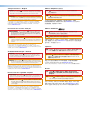
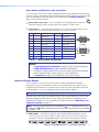
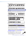
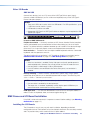
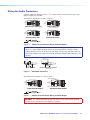
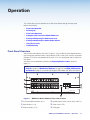
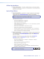
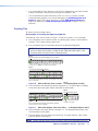
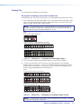
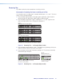
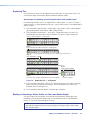
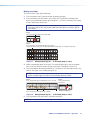
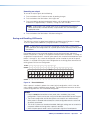
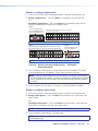
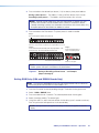
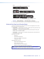
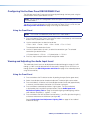
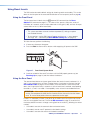
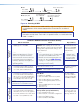
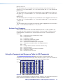
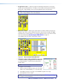
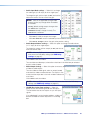
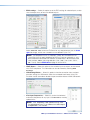
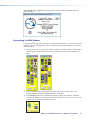
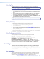
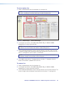
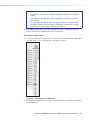
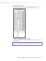
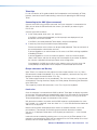
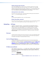
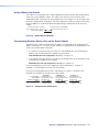
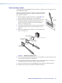
Wiring the Audio Connectors
Connect audio input devices to the 3.5 mm, 5-pole captive screw connectors (up to two
groups of eight sets possible).
Wire the input connectors as shown in figure 5.
L
L
Tip
Ring
Sleeves
Tip
Ring
Tip
Ring
Sleeve
R
R
Balanced Audio Output Input
Balanced Mono Input
(high impedance)
L
L
Tip
Sleeve
Tip
Sleeve
Tip
Sleeve
R
R
Unbalanced Stereo Input
Unbalanced Mono Input
Do not tin the wires!
Figure 5.
Captive Screw Connector Wiring for Audio Signals
NOTE: When making connections for the SMX from existing audio cables (see
figure 7). A mono audio connector consists of the tip and sleeve, whereas a stereo
audio connector consists of the tip, ring, and sleeve. The tip, ring, and sleeve wires are
also shown above on the captive screw audio connector diagram (balanced inputs, see
figure 6).
Tip (+)
Ring (-)
Tip (+)
Sleeve ( )
Sleeve ( )
RCA Connector
Figure 6.
3.5 mm Stereo Plug Connector
(balanced)
RCA Audio Connectors
Wire the output connectors as show in figure 7.
No Ground Here
R
R
Tip
Sleeves
Tip
L
L
Tip
Ring
Sleeves
Tip
Ring
No Ground Here
Balanced Audio Output
Unbalanced Audio Output
Do not tin the wires!
Figure 7.
Captive Screw Connector Wiring for Audio Output
CAUTION: For unbalanced audio, connect the sleeves to the center contact ground.
Do not connect the sleeves to the negative (-) contacts.
SMX System MultiMatrix Switcher • Installation and Cabling
12