1
INSTALLATION / OPERATION
EDR-920
9-channel Digital Video Recorder
EDR-1640
16-channel Digital Video Recorder
Rev 1.00
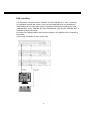
Safety warnings
Safety warnings
To avoid any damage, please consider the following safety warnings:
Never place the recorder near to heaters, furnaces, other heat sources or under
direct solar irradiation.
Operate the device only in locations providing the tolerable operating temperature
range 0°C~40°C.
Make sure that the device‘s ventilation slots are not covered or sheeted.
For cleaning, make sure the device is plugged off and only use a damp cloth without
acid detergent.
Install the device only in dry and dustproof surroundings. Protect the device against
any liquid‘s penetration.
Avoid the penetration of any artefacts, e.g. through ventilation slots.
Do not open the recorder yourself. In case of malfunction, contact your local installer
or dealer. Unauthorized opening of the device will annul the warranty claim!
Avoid any affection of the device through vibrations or mechanical shock at the
recorder‘s installation location.
Never remove harddisks during playback or recording operation.
Your EverFocus product is designed and
manufactured with high quality materials and
components which can be recycled and reused.
This symbol means that electrical and electronic
equipment, at their end-of-life, should be
disposed of separately from your household
waste.
Please, dispose of this equipment at your local
community waste collection/recycling centre.
In the European Union there are separate
collection systems for used electrical and
electronic product.
Please, help us to conserve the environment we
live in!
Ihr EverFocus Produkt wurde entwickelt und
hergestellt mit qualitativ hochwertigen Materialien
und Komponenten, die recycelt und wieder
verwendet werden können.
Dieses Symbol bedeutet, dass elektrische und
elektronische Geräte am Ende ihrer Nutzungsdauer
vom Hausmüll getrennt entsorgt werden sollen.
Bitte entsorgen Sie dieses Gerät bei Ihrer örtlichen
kommunalen Sammelstelle oder im Recycling
Centre.
Helfen Sie uns bitte, die Umwelt zu erhalten, in
der wir leben!
ATTENTION! This is a class A product which may cause radio
interference in a domestic environment; in this case, the user may be
urged to take adequate measures.
The information in this manual was current upon publication. The manufacturer reserves the
right to revise and improve his products. Therefore, all specifications are subject to change
without prior notice. Misprints reserved.
Please read this manual carefully before installing and using this unit. Be sure to keep it handy
for later reference.
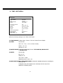
TABLE OF CONTENTS
1. Introduction
1.1 Features
1.2 Delivery scope
1.3 Technical data
1.4 Front panel operating elements
1.5 Connections
1.6 Screen displays
2. Installation
2.1 Delivery scope
2.2 Video connection installation, DVR cascading
2.3 Audio connection installation
2.4 RS-485 keyboard installation
2.4.1 General RS-485 bus installation
2.4.2 RS-485 connection assignment
2.4.3 EKB-500 connection through network patch cable
2.4.4 EKB-500 connection to several DVRs
2.5 Speed dome installation
2.6 Installation alarm inputs / outputs
2.7 PS2 mouse installation
2.8 Installation EDA800s harddisk expansion unit
2.9 Network connection
2.9.1 Direct PC connection through crossover cable
2.9.2 Network connection through patch cable
2.9.3 Network system requirements
2.10 Harddisks
2.11 Power connection
2.12 Start-up
3. Setup menu
3.1 Time / date
3.2 Camera
3.3 Recording
3.4 Alarm
3.5 Motion detection
3.6 Video loss
3.7 Network
3.8 Timer
3.9 HDD (harddisk)
3.10 RS232/RS485
3.11 Warning
3.12 System
4
4
4
5
7
10
12
15
15
15
17
18
18
20
20
21
22
23
24
24
25
25
25
25
26
26
26
27
28
31
34
36
38
41
42
46
47
48
49
53
TABLE OF CONTENTS
4. Recording
4.1 Normal recording
4.2 Timer – scheduled recording
4.3 Event recording
5. Playback
5.1 Playback without search function
5.2 Recording search
6. Video export
7. Call- / matrix monitor setup
8. Display settings
9. Screen display
10. EDA 966 infrared remote control (optional)
11. Network access
Appendix A: EDR viewer software
Appendix B: Interface specification
Appendix C: Serial remote control protocol
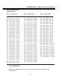
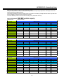
Appendix D: Recording times
56
56
56
57
58
58
60
62
64
65
66
67
68
73
75
76
81
1. INTRODUCTION
The latest EverFocus digital video recorder generation is based on MPEG-4 compression technology,
resulting in enhanced recording capacity and improved network image transmission speed with high
image quality.
Comprehensive features and extended event recording settings enable the almost universal
application of this DVR series.
1.1 FEATURES
• Duplex operation: simultaneous recording and playback
•
•
•
•
•
•
•
•
•
•
•
•
•
•
MPEG4 compression method with configurable quality
variable recording rate up to 400/200 images / second (EDR1640/920)
4-channel audio recording
motion detection
2 x 3,5“ HDD, expandable to max. 50 HDD with EDA800S (optional)
network interface for image transmission
RS232 and RS485 interfaces for remote control
Jog/shuttle for convenient recording evaluation
5 additional monitors
cascading function for keyboard administration of several EDR on one main monitor
easy-to-use front panel operation
multilingual on-screen display
real-time live display
facile video export function via USB stick or CF card
1.2 DELIVERY SCOPE
1. Ordered type of EDR 920/1640 digital video recorder
2. 2 x harddisk tray with harddisk according to order
3. 2 x installation frames for 19“ installation
4. 2 x harddisk tray keys
5. Adaptor board for alarm and control contacts
6. Mains supply
7. 120 Ohm termination with RJ-45 plug for RS-485 bus termination
8. Manual and quick reference guide
4
1.3 TECHNICAL DATA
Video format
PAL/CCIR
EDR920: 9 x 1 Vpp FBAS, BNC, 75 Ohm
Video input
EDR1640: 16 x 1 Vpp FBAS, BNC, 75 Ohm
Main monitor:
Video output
1 Vpp FBAS, BNC at 75 Ohm
CALL/MATRIX monitor: 5 x 1 Vpp FBAS, BNC at 75 Ohm
9/16 x loop-through outputs 1 Vpp FBAS, BNC at 75 Ohm
Video compression
MPEG4
Recording resolution
720x288, 720x576 or 360x288
Main monitor: full screen, PiP, 4,7,9,10*,13*,16* , 2 x zoom, sequence
Display modes
Call/matrix monitor: full screen, sequence
(*only EDR1640)
Alarm inputs
EDR920: 9 x NO/NC, EDR1640: 16 x NO/NC
Alarm outputs
4 x relay contacts 100 VDC max, 0, 3 ADC max, 5 W max.
Harddisk
3,5" IDE harddisk
EDR920
EDR1640
360x288: 200 images / second
400 images / second
720x288: 100 images / second
200 images / second
720x576:
100 images / second
Recording rate
50 images / second
Recording modes
Continuous recording, schedule or event recording
Playback rate
Real-time playback in full screen, PiP and 4x screen
Playback search functions
Via time / date or event (alarm / motion)
Adjustable per channel with 10 sensitivity steps and 20x24 sensor
Motion detection
fields each
Video loss detection
Adjustable per camera
Event log
10240 entries per harddisk
Setup
On-screen display
Operation
Via front panel or optional IR or RS-485 operation
Real-time clock
Internal with network synchronisation option (NTP server)
Watchdog function
For processing, ventilation, harddisk, harddisk temperature
5
Title generator
Max. 12 characters per camera
Network
RJ45 socket
Image export
USB 2.0 interface
RS-232
9-pin Sub-D socket
RS-485
2 x RJ45
4 x input 500 mV max /10KOhm,
Audio
1 x output 500 mV max at 10KOhm
Power source
100 ~ 240 VAC
Power consumption
185 W max.
Dimensions
430 (W) x 88 (H) x 300 (D) mm
Weight
6,24 KG
Ambient temperature
0 C ~ +40 C
Remote control
optional: IR remote control, RS-485 keyboard
o
o
6
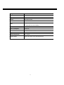
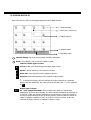
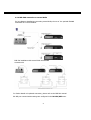
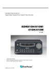
1.4 FRONT PANEL OPERATING ELEMENTS
9
21
19
20
11
13
8
10
12
14
1
3
5
7
17
15
18
23
2
4
6
16
Keys
1
REC: recording key
2
STOP: recording / playback stop
3
PLAY: playback
4
PAUSE: image freeze, stops playback for freeze mode
5
SEARCH: opens on-screen display for playback search
6
COPY: opens image export menu. In playback mode, the current playback position is
stored as image export start position.
7
ENTER: Enter key for input confirmation
8
DISPLAY: main monitor status display switching:
7
22
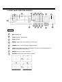
9
SELECT: In multiscreen mode: selection of the camera to be displayed in a partial screen.
ENTER switches to the following partial screen.
In full screen mode: brightness, contrast and colour adjustment for this video channel.
10
MODE: Multiscreen display switching, repeated actuation switches between the individual
displays.
11
ZOOM: In full screen mode: 2x electronical zoom. Zoom screen can be moved through JOG .
ENTER key changes the direction. Further zoom key actuation switches the electronical zoom
off.
In multiscreen mode: Image orientation adjustment. Use the JOG to adjust the image to the
respective monitor type. ENTER switches between horizontal and vertical adjustment .
Further ZOOM key actuation switches the adjustment off.
12
SEQ: Sequence operation, automatic image switching
13
CALL: On-screen display start for call and matrix monitor setup
14
MENU: Setup menu start
15
Jog / Shuttle
Shuttle (outward): In playback mode, use the SHUTTLE for fast
forward / reverse playback.
In PAUSE mode, turn the shuttle to the right for slow forward playback
(1/2 up to 1/8).
In SEARCH MENU, use the shuttle to page down the event log list.
JOG: In PAUSE mode, use the jog to switch freeze images forwards /
backwards.
Within menu functions, use the jog to adjust the values / parameters.
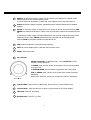
16
System LEDs: Status LEDs for LAN activity, alarm, internal / external HDD access
17
Channel keys: Video channel key to select a single camera for full screen display
18
HDD lock: HDD lock and switch
19
Harddisk tray: Trays for 3,5" HDD
8
20
HDD LEDs: LEDs for HDD power (green) and HDD activity (red)
21
LCD display: Status, time/date display
22
IR receiver: Receiver for infrared remote control
23
USB socket: USB-2.0 port for image export via USB stick resp. external DVD-R EPR200
9
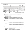
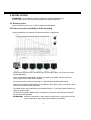
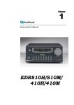
1.5 CONNECTIONS
5
10
8
4
3
15
14
2
7
6
9
12
1
11
EDR1640 back panel (EDR920 identical, 9 video inputs)
13
1
Main switch: Power switch, below IEC socket for 100~240 VAC power source
2
Audio inputs: Audio inputs 1 ~ 4
Audio output: Audio output
3
MAIN monitor: Main monitor for live and playback display and on-screen display
4
CALL monitor: CALL monitor output. Spotmonitor for full screen live display, sequence
mode and alarm camera switching
5
Video inputs:
EDR920:
VIDEO IN(1~9): BNC video inputs for 1 Vpp Composite video signals, automatic 75 Ohm
termination (high impedance switching upon loop-through output load)
EDR1640:
VIDEO IN (1~16): BNC video inputs for 1 Vpp Composite video signals, automatic 75 Ohm
termination (high impedance switching upon loop-through output load)
6
Alarm and control inputs / outputs (for connection assignment, refer to appendix C)
ALM-INPUT:
9 (EDR920) resp. 16 (EDR1640) alarm inputs for dry contacts,
programmable NO or NC in the menu.
ALM-OUTPUT: 4 x NO/NC alarm output relay
REC-IN:
Input contact for recording start, NO, for dry contacts
10
7
LAN: RJ45 network socket
8
RS232 socket: 9-pin Sub-D control input for RS-232 remote control
9
RS485 socket: 2 x RJ45 socket (equal) for remote control via RS-485
keyboards and telemetry control (network-controlled)
10
Fan: Fan air outlet, please do not cover
11
Matrix monitors 1~4: Matrix monitor outputs 1~4
12
SCSI-socket: EDA800s HDD expansion unit connection
13
Mouse: PS-2 mouse connection (optional)
14
S-Video: Main monitor Y/C output
15
Cascade IN / OUT: Monitor input / output for EDR cascading. This function allows one
monitor to be used for MAIN monitor display of several DVRs. Function is only available
upon DVR control through RS-485 keyboards.
11
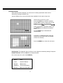
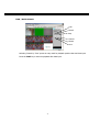
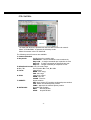
1.6 SCREEN DISPLAYS
Here’s an overview of the screen displays appearing on the MAIN monitor:
1. Channel display
2. Event (here: video loss)
3. Display selection
4. Playback status
5. Recording status
1
Channel display: shows the selected video channel’s description
2
Event: Event display, may be channel-related or global
Channel-related types of event:
A
Alarm: Display of an alarm triggered by alarm input contact
M
Motion: Motion detection of the respective camera
V
Video loss: Video signal loss of the respective camera
S
Sequence: Sequential operation of the respective video channel
* - In multiscreen display, this icon indicates the channel selected for sequential
display. Selection via SELECT key. Upon sequence activation, the “*” icon is replaced
by S
Global types of event:
OT
OT - Over Temperature HDD: Alarm message upon HDD over temperature,
displayed in red on all video channels. The device should immediately be switched off.
In case the „FAN“ (fan damage) message occured previously, contact the technical
service for trouble shooting. If the fan works properly, check the device‘s position as
regard to ambient temperature (max. 40°C, fan must not be covered, ensure the
sufficient ventilation if device is installed in cabinet or rack).
12
3
SELECT: Within a multiscreen view, the SELECT key activates the camera selection mode. The
active camera field shows “S”.
Use the JOG to switch between the camera fields. Use the channel keys 1~9 or 1~16 to switch
the channel..
4
PLAYBACK STATUS: The playback-relevant information are displayed in this status bar.
Playback date
Playback status
Playback position
1. Playback date : Current playback date
2. Playback status: Playback operation mode
“PAUSE”:
Freeze image mode
“>”:
normal playback speed
“<“
reverse playback, normal speed
“>> x N” : forward playback, Nx speed
“<< x N”:
reverse playback, Nx speed
"XX%":
playback position in XX percent of total HDD capacity
3. Playback position:
5
current playback position, display format depends on
time/date menu settings
RECORDING STATUS: The recording-relevant information are displayed in this status bar.
Current date
Recording status
Event
HDD/FAN Alarm
13
Current time
1. Current date: as set in time/date menu
2. Recording status: In case of activated recording, "R" + current HDD no. is displayed
“R01”: R - RECORD, figure shows the currently recording HDD no., here: No. 1
3. Event: current event display
4. Current time: as set in time/date menu
5. HDD fan message:
“No Disk”: no HDD available or detected
“No Fan”: fan malfunction
"HDD OT": HDD over temperature
14
2. INSTALLATION
ATTENTION: The installation should be effected by qualified personnel only.
Connect power source only after having finished the further installation.
2.1 Delivery scope
Check the delivery scope (see 4.) before starting the installation.
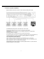
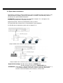
2.2 Video connection installation, DVR cascading
Sample installation with maximum camera and monitor configuration:
Cameras and monitors have to be cabled with 75 Ohm video cable, e.g. RG-59, RG-12 and
suitable BNC plugs.
Due to inappropriate absorbability, 50 Ohm coax cable (e.g. RG58), antenna cable and
further types of coax cable are not suitable.
All connected video sources must provide a 1 Vpp PAL/CCIR standard video signal.
When interconnecting transmission lines (twisted pair, fibre optics, radio) to the video inputs,
ensure the accurate receiver calibration.
The MAIN monitor may optionally be connected through a Y-C (S-Video) cable to achieve an
improved image quality.
For local DVR operation, MAIN monitor connection is compulsory. Call and matrix monitors
can be connected optionally.
ATTENTION: Make sure that there‘s a video signal on video input 1 upon start-up, as this
input is required for video system auto detection (PAL/NTSC)!
15
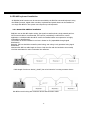
DVR cascading
The digital video recorders provide "CASCADE IN" and "CASCADE OUT" video connections.
In combination with RS-485 remote control, up to 8 EDR920/1640 can be cascaded and
administrated via one single main monitor. Cascading is effected by connecting the DVRs
„CASCADE OUT“ to the „CASCADE IN“ of the following DVR, while the last „CASCADE OUT“ is
connected to the monitor input.
By means of the RS-485 address sent from the keyboard, the respective DVR is switched on
the monitor.
This function is available for main monitor only.
Installation with 3 cascaded EDR and EKB-500
16
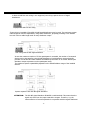
2.3 Audio connection installation
Sample installation with audio connection to video cameras providing audio output:
The EDR920/1640 DVRs provide 4 audio inputs and 1 audio output.
The inputs are designed for max. 500 mV to 10 KOhm line audio signals.
ATTENTION: The direct connection of a non-amplified microphone is not supported (a
microphone amplifier is required).
The installation has to be effected with audio coax cable and RCA plugs.
The output provides a max. 500 mV to 10 KOhm line audio signal and may be connected to e.g.
a monitor‘s audio input. The direct connection of (passive) speakers is not supported.
AUDIO RECORDING FUNCTIONALITY:
Audio recording is activated / deactivated in the RECORDING menu for all channels.
Audio of all channels is always recorded together with (each) video and is independent of the
image recording rate. There is no specific camera allocation.
During playback, use the JOG to select the requested playback channel 1~4 (active channel is
indicated in playback on-screen display).
17
2.4 RS-485 keyboard installation
All EDR920/1640 functions can be remote-controlled by the EKB 500 universal keyboard. Using
the EEPbus protocol, digital video recorders, keyboards and speed domes can be installed on
one single RS-485 bus. One system can comprise up to 8 keyboards.
2.4.1 General RS-485 bus installation
EKB-500 uses an RS-485 simplex wiring; the signal is transferred via a single twisted pair line.
CAT5 network cable is recommended, UPT version (unshielded) is sufficient for normal
application. A shielded cable should be used if the installed cables are expected to be highly
susceptible to interferences.
The number of devices installed in one bus is limited to 32 (expandable through signal
distributors).
Basically, the bus should be created by serial wiring, star wiring is only permitted using signal
distributors.
Maximum RS-485 bus cable length is 1200 m. Both the first and the last device are normally
120 Ohm terminated in order to minimize line reflexions.
RS-485 bus serial wiring
Cable length from box to device („Stubs“) has to be limited to 2m using connector boxes.
RS-485 bus serial wiring with connector boxes and connection cable
18
A direct RS-485 bus star wiring is not supported; star wiring requires the use of signal
distributors.
Improper RS-485 bus star wiring
If star wiring is inevitable, EDA 997A RS-485 signal distributors may be used. The maximum system
cable length can also be expanded by using these distributors, physically providing a new RS-485
bus with 1200 m cable length each at every distributor output.
Star wiring with RS-485 signal distributor
In case the maximum number of 32 bus participants is exceeded, the number of connected
devices can be increased by using RS-485 distributors. Each distributor output physically
provides one RS-485 bus which enables the additional connection of 31 further devices (the
distributor output represents one bus participant itself).
The maximum system expandability depends on the RS-485 address range of the installed
devices.
System expansion with RS-485 signal distributor
ATTENTION: The RS-485 signal distributor EDA997A is unidirectional! This means that the
signal only flows from the input towards the outputs. Therefore, e.g. the
interconnection of several keyboards is not possible with this signal distributor!
19
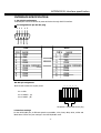
2.4.2 RS-485 plug connection assignment
The two RS-485 input RJ-45 plugs are looped through and pin-compatible. The following
RJ-45 plug assignment has to be considered for connection:
Pin 3: RS-485 +
Pin 6: RS-485 -
The following illustration shows the connector box assignment of the optional EDA998
connection kit (connector box, patch cable):
2.4.3 EKB-500 connection with network patch cable
For a simple, short distance installation, recorder and keyboard can directly be connected using a
standard network cable (patch cable, uncrossed!).
20
2.4.4 EKB-500 connection to several DVRs
For long distance installations connecting several DVRs, the use of the optional EDA998
connection kit is recommended:
EKB 500 installation with several DVRs and EDA998
connection kit
For further details on keyboard connection, please refer to the EKB 500 manual.
RS-485 port communication settings are configured in the RS-232/485 menu.
21
2.5 Speed dome installation
Speed dome or telemetry receiver pan/tilt/zoom control is available through web browser or the
optional PowerCon software if the DVR is connected to a network. Local telemetry control is
provided by the optional EKB 500 keyboard.
ATTENTION: The basic RS-485 wiring rules described in chapter 2.3.1. also apply to the
connection of speed domes or telemetry receivers.
Supported protocols: EverFocus, ED2200/2250, Pelco-D, Pelco-P
The optional RS-485 connection kit is recommended for easy installation.
For RS-485 port pin assignment, please refer to chapter 2.3.2.
Sample installation with 3 EPTZ1000 speed domes and EDA998
Sample installation with 3 EPTZ1000 speed dome, EDA998 and local EKB 500 operation
Required DVR settings: RS-485 receiver address in CAMERA menu
RS-485 parameters and protocol in RS232/485 menu
ATTENTION: Some Pelco-D / -P protocol domes and receivers require an address offset of -1,
i.e. the address assigned to the dome / receiver in the DVR camera menu
must be 1 below the address set in the dome / receiver itself!
22
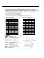
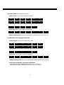
2.6 Alarm input / output installation
The EDR920/1640 alarm inputs can be used for recording start or recording rate adjustment.
Furthermore, alarm reactions such as camera switching to monitors, buzzer, e-mail and network alarm
are available. An alarm output relay can be switched if required.
EDR920 provides 9 alarm inputs, EDR1640 provides 16. All inputs are programmable NO/NC.
Inputs have to be switched through dry contacts.
The 4 output relays provide a dry NO/NC contact.
All settings are programmed in the ALARM menu.
Use either the 37-pin Sub-D plug or the included adaptor board for connection.
Pin assignment Sub-D plug
PIN #
1
2
3
4
5
6
7
8
9
10
11
12
13
14
15
16
17
18
NAME
GND
ALM 1
ALM 2
ALM 3
ALM 4
ALM 5
ALM 6
ALM 7
ALM 8
ALM 9
ALM 10
ALM 11
ALM 12
ALM 13
ALM 14
ALM 15
ALM 16
GND
DVR
PIN #
19
20
21
22
23
24
25
26
27
28
29
30
31
32
33
34
35
36
Pin assignment adaptor board
HOST
NAME
GND
ALM-NC0
ALM-NO0
ALM-COM0
ALM-NC1
ALM-NO1
ALM-COM1
ALM-NC2
ALM-NO2
ALM-COM2
ALM-NC3
ALM-NO3
ALM-COM3
ALMRSTO
REC
GIN1O
DISKFULL
GO1
Descriptions:
ALMINxx:
Alarm input xx (1~16)
GND:
common ground for alarm inputs
PIN #
NAME
PIN #
1
GND
21
NAME
GND
2
ALMIN 1
22
ALM_NC1
3
ALMIN 2
23
ALM_NO1
4
ALMIN 3
24
ALM_COM1
5
ALMIN 4
25
ALM_NC2
6
ALMIN 5
26
ALM_NO2
7
GND
27
ALM_COM2
8
ALMIN 6
28
GND
9
ALMIN 7
29
ALM_NC3
10
ALMIN 8
30
ALM_NO3
11
ALMIN 9
31
ALM_COM3
12
ALMIN 10
32
ALM_NC4
13
GND
33
ALM_NO4
ALM_COM4
14
ALMIN 11
34
15
ALMIN 12
35
GND
16
ALMIN 13
36
ALMRST
17
ALMIN 14
37
REC_IN
18
ALMIN 15
38
SPARE_IN
19
ALMIN 16
39
DISK_FULL
20
GND
40
SPARE_OUT
NO contact alarm input connection:
ALM_COMx: output relay x , contact root
ALM_NOx:
output relay x , NO contact
ALM_NCx:
output relay x , NC contact
ALMRST:
NC contact alarm input connection:
Alarm reset, control input for alarm
reset, for dry NO contact
towards GND
DISKFULL: OC output contact for signal
„HDD full“, switches to GND
REC_IN:
Output relay in idle state:
Control contact for recording start
SPARE_IN / OUT: reserved
23
2.7 PS/2 mouse installation
EDR920/1640 may optionally be controlled through PS/2 wheelmouse which must
be connected before system start-up.
2.8 Installation EDA800s harddisk expansion unit
The EDR920/1640 image storage capacity can be expanded using EDA800s harddisk expansion
units. Max. 6 EDA800s with 8 harddisks each can be connected via SCSI bus.
For installation details of the EDA-800S harddisk expansion unit, please refer to the EDA800s
manual.
24
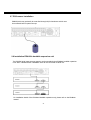
2.9 Network connection
EDR920/1640 DVRs provide fast MPEG-4 format image transmission and network remote
configuration.
This chapter doesn‘t go into basic network technique details. For further information, especially
about router installation and internet connection, please refer to the publication "EverFocus
network technique".
Physically, two basic types of connection are possible:
2.9.1. Direct PC connection through crossover network cable
The point-to-point connection of DVR and PC requires a crossover (crossed) network cable.
This type of connection does not allow the connection of several PCs or DVRs.
Make sure that the PC is equipped with a 100 MBit compatible network connection.
2.9.2. Network connection through patch cable
The connection to an existing network requires a normal patch cable (wired 1:1). The
illustration shows the connection to a network switch.
2.9.3. Network system requirements
Connection type: 100Base-T
Max. required network bandwidth: 10 MBit
Protocol types: TCP, UDP, SMTP, HTTP, NTP
Required ports: for port configuration, please refer to NETWORK menu
25
2.10 Harddisks
Insert the pre-assembled harddisks incl. frames into the HDD tray. Both harddisks must be
jumpered as „CS – Cable Select“.
Make sure that both harddisks have reached the stop position and use the key switch to lock the
harddisk tray.
ATTENTION: Use only harddisks approved for the use with EDR920/1640 DVRs.
ATTENTION: Harddisk shutdown and removal during recording and playback operation
and upon DVR system start is inadmissible!
ATTENTION: Upon harddisk shutdown through key switch, the harddisk is signed off from the
system. Do not remove the harddisk until the green power source LED at the
harddisk tray is extinguished.
2.11 Power connection
Connect the DVR to the power source (100~240 VAC 50/50 Hz) using the included IEC cable.
To ensure the secure DVR operation, the use of an uninterruptible power supply (UPS) in online
version with sufficient operating time is recommended.
2.12 Start-up
After having finished the installation work, switch on the power using the main power switch.
Depending on harddisk type and fill level, the start-up sequence might take up to 2 minutes.
The next step is the system menu setup.
26
3. SETUP MENU
All EDR DVR settings are carried out in the on-screen display.
MENU
The MENU key starts the main menu.
Press the MENU key again to leave the menu or to change from
sub menu to a higher menu level.
Use the JOG to select a menu item.
Use the ENTER key to confirm a selection and to proceed to the
next entry in sub menus.
Use the DISPLAY key to return to the previous entry in sub
menus.
MAIN MENU
TIME/DATE
CAMERA
RECORD
ALARM
MOTION
VLOSS
NETWORK
SCHEDULE
DISK
CONTROL
WARNING
SYSTEM
27
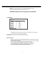
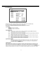
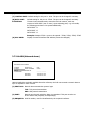
3.1 TIME / DATE MENU
TIME/DATE
TIME FORMAT
TIME
DATE FORMAT
DATE
24 HOUR
12:22:34
DD-MM-YYYY
12-11-2005
DAYLIGHT SAVING
START ON
FROM
END ON
FROM
ON
MAR LAST SU
02:00 TO 03:00
OCT LAST SU
03:00 TO 02:00
TIME SYNCHRONIZE
TIME SERVER
TIME ZONE
TIME UPDATE BY
ON
64.109.43.141
GMT+1
DAY
Define the following settings in the TIME / DATE menu:
(1) TIME FORMAT: Select either 12-hour or 24-hour format for time display
(2) TIME:
Current time
Hour: 00 ~ 23 (1 ~ 12 for 12-hour format)
Minute : 00 ~ 59
Second: 00 ~ 59
(3) DATE FORMAT: Select the date display format: YYYY-MM-DD, MM-DD-YYYY
or DD-MM-YYYY
(4) DATE:
Current date
Day: 01~31
Month:01~12
Year: 2000 ~ 2099
Weekday (autom.): MO ~ SU
(5) DAYLIGHT SAVING TIME ADJUSTMENT: Activate the daylight saving time switching by
selecting “ON".
If daylight saving time adjustment is activated, the next step is the
definition of switching terms.
28
(6) START DATE: Start daylight saving time
Select month: Use the JOG to adjust the month:
JAN
FEB
MAR
APR
MAY
JUN
JUL
AUG
SEP
OCT
NOV
DEC
Select week: Use the JOG to adjust the week of the selected month:
1.
2.
3.
4.
LAST
Select day: Use the JOG to adjust the weekday:
SU
MO
TU
WE
TH
FR
SA
Adjust switching time: Select the switching time (FROM) and the new time (TO).
(7) END DATE: End of daylight saving time
Select month: Use the JOG to adjust the month:
JAN
FEB
MAR
APR
MAY
JUN
JUL
AUG
SEP
OCT
NOV
DEC
Select week: Use the JOG to adjust the week of the selected month:
1.
2.
3.
4.
LAST
Select day: Use the JOG to adjust the weekday:
SU
MO
TU
WE
TH
FR
SA
Adjust switching time: Select the switching time (FROM) and the new time (TO).
Central Europe daylight saving time adjustment:
- Last Sunday of March: Adjustment from 02:00 a.m. to 03:00 a.m.
- Last Sunday of October: Adjustment from 03:00 a.m. to 02:00 a.m.
29
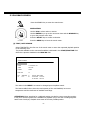
(8) TIME SYNCHRONISATION:
The DVR offers time synchronisation via NTP server.
ATTENTION: The synchronisation should be activated by selecting “ON” only after defining
the daylight saving time, time zone and NTP server IP address.
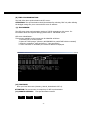
(9) TIME SERVER:
The NTP server time synchronisation requires a TCP/IP connection to this server. For
information about the required settings, please refer to “NETWORK” menu.
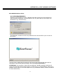
NTP server identification:
Time servers available on the internet can be identified as follows:
1. Connect your PC to the internet.
2. Open the “DOS prompt” (directory ACCESSORIES or path START>RUN>command)
3. Enter the command:" ping pool.ntp.org " (see screenshot)
4. If the connection is successful, the server IP address is displayed.
(10) TIME ZONE:
Enter your local time zone (Germany, Austria, Switzerland: GMT+1).
ATTENTION: The correct entry is compulsory for NTP synchronisation.
(11) UPDATE INTERVAL: Time synchronisation interval
DAY
WEEK
MONTH
30
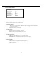
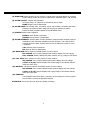
3.2 CAMERA MENU
CAMERA
CAMERA1
CAMERA2
CAMERA3
CAMERA4
CAMERA5
CAMERA6
CAMERA7
CAMERA8
CAMERA9
SUMMARY
TITLE
PTZ ID
INSTALL/COVERT
SEQ (MAIN/CALL)
REC QUALITY
CH1
01
ON/OFF
03/03 SECS
HIGH
REC SPEED ON TIME ZONE
TP NORMAL EVENT
SET
1
5 IPS
25 IPS
OFF
2
5 IPS
25 IPS
OFF
3
5 IPS
25 IPS
OFF
4
5 IPS
25 IPS
OFF
5
5 IPS
25 IPS
OFF
6
5 IPS
25 IPS
OFF
7
5 IPS
25 IPS
OFF
8
5 IPS
25 IPS
OFF
N 5 IPS
25 IPS
OFF
Menu display for EDR-920, EDR1640 identical, but with 16 cameras.
The most important recording operation settings are defined in the CAMERA menu.
Before changing the settings in this menu, recording has to be stopped.
Each camera is set individually:
(1) NAME:
Enter the video channel description with max. 12 characters each.
Available characters are (select with JOG):
0,1,2,3,4,5,6,7,8,9,
A,B,C,D,E,F,G,H,I,J,K,L,M,N,O,P,Q,R,S,T,U,V,W,X,Y,Z,
( ) . , + - / and space
(2) PTZ ID:
Enter the RS-485 receiver address of a speed dome or telemetry receiver camera
connected to this video channel.
(3) INSTALL / COVERT:
INSTALL (first position) All connected cameras have to be set to ON,
all not connected cameras are set to OFF.
ATTENTION: The manual setting is compulsory, autodetection for connected cameras is not
available!
COVERT (second position): A camera programmed COVERT “ON” will not be displayed, but
recorded at defined parameters.
(4) SEQ(MAIN/CALL): Camera dwell time in sequence operation (automatic switching) for
main (first position) and call (second position) monitor
ATTENTION: Some Pelco-D / -P protocol domes and receivers require an address offset of -1,
i.e. the address assigned to the dome / receiver in the DVR camera menu
must be 1 below the address set in the dome / receiver itself!
31
(5) REC QUALITY: Individual recording quality setting for this camera (within the resolution
defined in RECORDING menu):
SUPERIOR
HIGH
STANDARD
BASIC
LOW
LOWER
Using the VBR (Variable Bit Rate) method, the storage requirement per image
depends on the image’s colour and contrast content and captured motion.
For recording time sample tables, please refer to Appendix D.
(6) REC SPEED ON TIME ZONE:
The EDR DVR offers 8 different timers for scheduled recording. The settings of the last
row “N” (normal) apply to those periods not captured by a timer schedule (setup in
TIMER menu)
For recording rate, the following steps are available: 1;2;3;4;5;6;8;10;12,5;25 images/s.
In case no timer is activated, the DVR only operates according to the settings of row “N”.
TP: Timer program 1~8, schedule setup and activation are defined in the TIMER menu.
N: (Normal) all periods not captured by a timer schedule.
In case no timer is activated, the DVR only operates according to these settings.
NORMAL: IPS recording rate for manual or scheduled recording and recording controlled through
“REC IN” input contact. The maximum image rate is limited to:
Max. image rate per camera = max. DVR recording rate / number of installed cameras.
Max. DVR recording rate depends on recording resolution:
EDR920: 360x288: 200 image / second
720x288: 100 images / second
720x576: 50 images / second
EDR1640: 360x288: 400 images / second
720x288: 200 images / second
720x576: 100 images / second
Example: EDR1640 with 12 installed cameras, resolution 720x288:
200 IPS : 12 = 16,6 IPS > maximum adjustable recording rate per camera: 12,5 IPS
32
EVENT: IPS recording rate for event recordings (alarm contacts, motion
detection), maximum adjustable recording rate is 25 IPS.
ACT (active): Indication of whether the individual timer is activated. Settings
are carried out in TIMER menu. ON: timer activated; OFF: timer deactivated
(7) SUMMARY:
CAMERA
CAMERA1
CAMERA2
CAMERA3
CAMERA4
CAMERA5
CAMERA6
CAMERA7
CAMERA8
CAMERA9
SUMMARY
ITEM
1
2
3
4
5
6
7
8
9
TITLE
CH1______
CH2______
CH3______
CH4______
CH4______
CH4______
CH4______
CH4______
CH4______
Menu display for EDR-920, EDR1640 identical, but with 16 cameras
The SUMMARY menu item gives a summary on the settings for control purpose.
Use the JOG to browse the individual settings.
ATTENTION: This menu does not allow any editing of settings.
(8) COPY function
Besides camera title, PTZ ID and INSTALLED/COVERT, the settings can be copied
from one camera to another.
Select the camera to be copied from the camera list on the left and press the COPY
key. The message “COPIED” appears at the top screen margin.
Select the camera which shall apply the settings from the camera list.
Press the SEARCH key to assign the copied settings to the camera.
The message “PASTED” appears at the top screen margin.
33
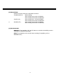
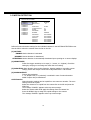
3.3 RECORDING MENU
RECORDING
RECORD AUDIO
YES
TIME STAMP
TIME STAMP POS.
WATERMARK
WATERMARK POS.
RESOLUTION
RECORD MODE
OFF
BOTTOM
OFF
TOP
720X288
REWRITE
Define the following settings in the recording menu:
(1) RECORD AUDIO:
YES: Audio is recorded together with video. Audio recording is effected independent
of image recording rate.
NO: Audio recording is deactivated.
(2) TIME STAMP:
ON: Recording is overlaid by time and date.
OFF: Recording doesn’t provide time/date stamp.
(3) TIME STAMP POS.:
TOP: Time / date is displayed at the top screen margin.
BOTTOM: Time / date is displayed at the bottom screen margin.
(4) WATERMARK :
ON: Recording is overlaid by a visible watermark ("W").
OFF: No watermark.
34
(5) RESOLUTION:
DVR PAL recording resolution is adjustable as follows:
720x288 (Half D1),
Default setting,
total recording rate 100 IPS for EDR920
total recording rate 200 IPS for EDR1640
720x576 (D1) ,
total recording rate 50 IPS for EDR920
total recording rate 100 IPS for EDR1640
or
360x288 (CIF) ,
total recording rate 200 IPS for EDR920
total recording rate 400 IPS for EDR1640
(6) RECORD MODE:
REWRITE: If the harddisk is full, the DVR starts to overwrite the harddisk, previous
recordings are deleted automatically.
STOP: If the harddisk is full, the DVR stops recording (for signalling, refer to
WARNING menu).
35
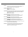
3.4 ALARM MENU
ALARM
ALARM 1
ALARM 2
ALARM 3
ALARM 4
ALARM 5
ALARM 6
ALARM 7
ALARM 8
ALARM 9
SUMMARY
ALARM
ALARM TYPE
ENABLE
N.O.
ACTIVE CAMERA
DURATION
ALARM OUTPUT
ALARM EMAIL
BUZZER
ALARM NETWORK
01
05 SEC
NONE
NO
OFF
NO
MAIN MON
CALL MON
MATRIX 1
MATRIX 2
MATRIX 3
MATRIX 4
NO CHANGE
NO CHANGE
NO CHANGE
NO CHANGE
NO CHANGE
NO CHANGE
Menu display for EDR-920, EDR1640 identical, but with 16 alarm inputs.
Define the dry alarm contacts’ attributes and the alarm reactions in the ALARM menu.
For alarm contact pin assignment, please refer to appendix D.
Each contact is adjusted individually and selected from the list on the left:
(1) ALARM:
ENABLE: Contact is activated.
DISABLE: Contact is deactivated.
(2) ALARM TYPE:
N.O. : Normally open, contact reacts on being connected to ground (GND). Define the
alarm duration within menu item DURATION.
N.C.: Normally closed, contact reacts on being disconnected from ground (GND). Define the
alarm duration within menu item DURATION.
N.O. + Trans.: Transparent mode, similar to normally open but: alarm is active as long as
input contact (but minimal as defined in DURATION)
N.C. + Trans.: Transparent mode, similar to normally closed but: alarm is active as long as
input contact (but minimal as defined in DURATION)
(3) ACTIVE CAMERA:
Alarm camera being recorded and displayed in full screen on the main monitor (see
(10) MAIN MONITOR). Recording is carried out according to the settings defined
for EVENT within the CAMERA menu.
COPY function
Alarm settings can be copied from one contact to another. Select the contact to be copied from the
contact list on the left and press the COPY key. The message “COPIED” appears at the top screen
margin. Select the contact which shall apply the settings from the contact list. Press the SEARCH key to
assign the copied settings to the contact. The message “PASTED” appears at the top screen margin
36
(4) DURATION: Alarm duration for N.O. and N.C. contact types. Duration applies to recording,
screen change, buzzer and output contact and is adjustable from 1~99 seconds.
(5) ALARM OUTPUT: Output relay activation.
1: Output relay 1~4 (selection) is switched in case of alarm
NONE: Output relay is deactivated.
(6) ALARM EMAIL: By selecting “ON”, an email is sent in case of alarm, containing the alarm
message, the camera’s alarm image and the DVR IP address as sender.
Define the email recipiant’s details in the NETWORK menu.
(7) BUZZER: Alarm buzzer activation
ENABLE: Alarm buzzer is activated.
DISABLE: Alarm buzzer is deactivated.
(8) ALARM NETWORK: Network alarm function activation. Network alarm reception requires
installation of the optionally available PowerCon software. The network alarm
transmits both the alarm message and the DVR IP address as sender to up to
3 recipiants.
YES: Network alarm is activated.
NO: Network alarm is deactivated.
(10) MAIN MON: Alarm reaction on MAIN monitor in case of alarm.
NO CHANGE: The currently selected main monitor display does not change.
FULL SCREEN: Monitor displays the alarm camera (see (3)) image in full screen.
(11) CALL MON: Alarm reaction on CALL monitor in case of alarm.
NO CHANGE: The currently selected call monitor display does not change.
Camera 1~9 (16): Monitor displays full screen image of the camera defined
within the menu item.
(12) MATRIX 1 ~ 4: Alarm reaction on MATRIX monitor in case of alarm.
NO CHANGE: The currently selected matrix monitor display does not change.
Camera 1~9 (16): Monitor displays full screen image of the camera defined
within the menu item.
(13) SUMMARY
The SUMMARY menu item gives a summary on the settings for control purpose.
Use the JOG to browse the individual settings.
ATTENTION: This menu does not allow any editing of settings.
37
3.5 MOTION DETECTION
MOTION SETUP MENU
CAMERA 1
CAMERA 2
CAMERA 3
CAMERA 4
CAMERA 5
CAMERA 6
CAMERA 7
CAMERA 8
CAMERA 9
SUMMARY
MOTION
SENSITIVITY
ENABLE
07
DURATION
ALARM OUTPUT
E-MAIL
NETWORK
BUZZER
05 SEC
01
NO
NO
DISABLE
MAIN MON
CALL MON
MATRIX 1
MATRIX 2
MATRIX 3
MATRIX 4
NO CHANGE
NO CHANGE
NO CHANGE
NO CHANGE
NO CHANGE
NO CHANGE
Menu display for EDR-920, EDR1640 identical, but with 16 cameras.
Define all motion detection settings for the individual cameras in the MOTION DETECTION menu.
Use the JOG to select the cameras from the list on the left.
(1) MOTION:
ENABLE: Motion detection is activated.
DISABLE: Motion detection is deactivated.
ATTENTION: Motion detection is automatically deactivated upon opening an on-screen display!
(2) SENSITIVITY:
Define the trigger sensitivity in 10 steps (1 – lowest, 10 – highest). Check the
setting by carrying out a moving test within the zone setting.
(3) DURATION: Alarm duration upon motion detection. Duration applies to recording, screen
change, buzzer and output contact and is adjustable from 1~99 seconds.
(4) ALARM OUTPUT:
Output relay activation.
1 ~ 4: Output relay 1~4 (selection) is switched in case of motion detection.
NONE: Output relay is deactivated.
COPY function
Motion detection settings can be copied from one camera to another. The zone
settings cannot be copied.
Select the camera to be copied from the camera list on the left and press the
COPY key.
The message “COPIED” appears at the top screen margin.
Select the camera which shall apply the settings from the camera list.
Press the SEARCH key to assign the copied settings to the camera.
The message “PASTED” appears at the top screen margin.
38
(5) EMAIL:
By selecting “ON”, an email is sent in case of motion alarm, containing the alarm
message, the camera’s alarm image and the DVR IP address as sender.
Define the email recipiant’s details in the NETWORK menu.
(6) BUZZER: Alarm buzzer activation
ENABLE: Alarm buzzer is activated.
DISABLE: Alarm buzzer is deactivated.
(7) NETWORK: Network alarm function activation. Network alarm reception requires installation
of the optionally available PowerCon software. The network alarm transmits both
the alarm message and the DVR IP address as sender to up to 3 recipiants.
YES: Network alarm is activated.
NO: Network alarm is deactivated.
(8) MAIN MON: Alarm reaction on MAIN monitor in case of motion alarm.
NO CHANGE: The currently selected main monitor display does not change.
FULL SCREEN: Monitor displays the alarm camera image in full screen.
(9) CALL MON: Alarm reaction on CALL monitor in case of motion alarm.
NO CHANGE: The currently selected call monitor display does not change.
FULL SCREEN: Monitor displays the alarm camera image in full screen.
(10) MATRIX 1 ~4: Alarm reaction on MATRIX monitor in case of motion alarm.
NO CHANGE: The currently selected matrix monitor display does not change.
FULL SCREEN: Monitor displays the alarm camera image in full screen.
(11) SUMMARY: The SUMMARY menu item gives a summary on the settings for control purpose.
Use the JOG to browse the individual settings.
This menu does not allow any editing of settings.
ATTENTION: The DVR’s motion detection has been developed for recording control, not for
use as central alarm station, especially with connection to security services.
The manufacturer is not liable for loss or charges resulting from such
application, e.g. through false alarm triggering.
39
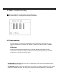
(10) AREA SETUP
With activated motion detection, the sub menu for setting up detection areas can be
entered by pressing the SELECT key.
Use the DISPLAY key to show all function keys available for this menu at any time.
Active areas are shown in green.
Press the COPY key to start the selection.
Use the JOG to raise a window and use the
ENTER key to switch the jog direction
between vertical
and horizontal
.
Having selected the requested window, use
the SEARCH key to activate the selected
areas.
DISPLAY KEY FOR HELP
Use the PAUSE key to deactivate the
selected areas.
If several or combined detection areas are
required, this procedure kann be repeated
as often as necessary.
Press the MENU key to leave this sub menu.
DISPLAY KEY FOR HELP
Moving test: The triggered areas are shown in red. Adjust the sensitivity settings if required.
Delete all areas: Press the PLAY key to delete all areas.
On-screen help menu (start with DISPLAY):
MENU
- EXIT
COPY
- SELECT AREAS
ENTER
- DIRECTION
SEARCH
- ACTIVATE AREAS
PAUSE
- DEACTIVATE AREAS
40
3.6 VIDEO LOSS MENU
VLOSS SETUP MENU
CAMERA 1
CAMERA 2
CAMERA 3
CAMERA 4
CAMERA 5
CAMERA 6
CAMERA 7
CAMERA 8
CAMERA 9
SUMMARY
VLOSS
ENABLE
DURATION
ALARM OUTPUT
ALARM EMAIL
BUZZER
ALARM NETWORK
05 SEC
01
NO
DISABLE
NO
Menu display for EDR-920, EDR1640 identical, but with 16 cameras.
Define the reaction upon video signal loss for each camera in this menu:
(1) VLOSS:
ENABLE: Video loss detection is activated.
DISABLE: Video loss detection is deactivated.
(2) DURATION: Alarm duration. Duration applies to buzzer and output contact and is adjustable
from 1~99 seconds.
(3) ALARM OUTPUT: Output relay activation.
1: Output relay 1 ~ 4 (selection) is switched in case of alarm
NONE: Output relay is deactivated.
(4) ALARM EMAIL: By selecting “ON”, an email is sent in case of alarm, containing the alarm
message and the DVR IP address as sender.
Define the email recipiant’s details in the NETWORK menu.
(5) BUZZER:
Alarm buzzer activation
ENABLE: Alarm buzzer is activated.
DISABLE: Alarm buzzer is deactivated.
(6) ALARM NETWORK: Network alarm function activation. Network alarm reception requires
installation of the optionally available PowerCon software. The network alarm
transmits both the alarm message and the DVR IP address as sender to up to
3 recipiants.
YES: Network alarm is activated.
NO: Network alarm is deactivated.
(10) SUMMARY: The SUMMARY menu item gives a summary on the settings for control purpose.
Use the JOG to browse the individual settings.
ATTENTION: This menu does not allow any editing of settings.
41
3.7 NETWORK MENU
Define all network-related settings in this menu.
These settings should only be carried out by skilled personnel qualified for network installation; if
the DVR is implemented in existing networks, the network administrator should be consulted.
This chapter doesn‘t go into basic network technique details. For further information, especially
about router installation and internet connection, please refer to the publication "EverFocus
network technique".
3.7.1 NETWORK
NETWORK SETUP MENU
CONFIG
ALARM
EMAIL
PASSWORD
DHCP
IP ADDRESS
SUBNET MASK
GATEWAY
DNS SERVER
NO
192.168.001.200
255.255.255.0
192.168.001.100
192.168.001.110
HTTP PORT
CONTROL PORT
DATA PORT
00080
01600
37260
MAC ADDR 00:11:14:01:83:2A
Define the basic DVR TCP/IP settings in the NETWORK menu:
(1) DHCP:
DHCP ( Dynamic Host Communication Protocol), automatic IP number
assignment (if supported by the network).
YES: DHCP activated
NO: DHCP deactivated.
(2) IP ADDRESS: Enter the DVR’s IP address.
If DHCP is activated, IP address is assigned automatically.
(3) SUBNET MASK: Local network subnet mask:
If DHCP is activated, subnet mask is assigned automatically.
(4) GATEWAY: Network gateway IP address for external access.
If DHCP is activated, gateway address is assigned automatically.
(5) DNS SERVER: Local network DNS server IP address.
If DHCP is activated, DNS server address is assigned automatically.
42
(6) HTTP PORT:
Default setting for this port is: 80. The port can be changed if necessary.
(7) CONTROL PORT: Default setting for this port is: 1600. The port can be changed if necessary.
(8) DATA PORT:
Default setting for this port is: 37260. The port can be changed if necessary.
ATTENTION:
If several users simultaneously access the DVR via network, each user
requires a DATA PORT (max. 4 users). Upon activating ports, e.g. in firewalls,
the following ports have to be opened additionally:
DATA PORT +1
DATA PORT +2
DATA PORT +3
Example: Dataport 37260 > ports to be opened : 37260, 37261, 37262, 37263
(9) MAC ADDR:
Display of network interface MAC address (cannot be changed).
3.7.2 ALARM (Network alarm)
NETWORK SETUP MENU
CONFIG
ALARM
EMAIL
PASSWORD
PROTOCOL
PORT NUMBER
UNIQUE ID
UDP
01600
_________
SERVER1
SERVER2
SERVER3
192.168.001.122
192.168.001.123
192.168.001.124
Having installed the optionally available PowerCon software, the DVR can transmit a network alarm to
up to 3 recipiants in case of event.
(1) PROTOCOL: Network alarm transmission protocol type
TCP: TCP protocol transmission
UDP: UDP protocol transmission
(2) PORT :
Network port through which the alarm is transmitted. This port must be set
at the client’s side (recipiant) correspondingly.
(3) UNIQUE ID: DVR ID number, used for identification by the recipiant’s software.
43
(4) SERVER 1 : Alarm server 1 IP address (recipiant)
(5) SERVER 2 : Alarm server 2 IP address (recipiant)
(6) SERVER 3 : Alarm server 3 IP address (recipiant)
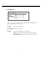
3.7.3 EMAIL (Email alarm)
NETWORK SETUP MENU
CONFIG
ALARM
EMAIL
PASSWORD
SMTP
SERVER
_____________
_____________
_____________
PORT NUMBER
00025
AUTHENTICATION NO
USER
_____________
_____________
PASSW.
_____________
_____________
_____________
_____________
_____________
EMAIL
ADR
Define the recipiant’s email account settings for email alarm in the EMAIL menu item. Email
alarms can be sent upon motion, alarm contact and technical alarms (WARNING menu).
An *.arv file format alarm image is transmitted upon motion and alarm contact alarms. The
visibility of these images requires installation of the EDR viewer software on the recipiant’s PC.
The software may either be copied to USB stick in the COPY menu or be downloaded from the
EDR browser through network connection (mouse click on EverFocus logo).
(1) SMTP SERVER:
(2) PORT:
Email recipiant’s SMTP server
SMTP server port number
(3) AUTHENTICATION: “YES“ if SMTP server requires login with user name / password.
“NO” if SMTP server doesn’t require login.
(4) USER:
SMTP server user name
(5) PASSW:
SMTP server password
(6) EMAIL ADDR: Alarm recipiant’s email address
44
3.7.4 PASSWORD
NETWORK SETUP MENU
CONFIG
ALARM
EMAIL
PASSWORD
NAME
PASSWORD
1 ADMIN___ *********
2 USER2___ *********
3 USER3___ *********
4 USER4___ *********
5 USER5___ *********
6 USER6___ *********
LEVEL
PLAY
LIVE
LIVE
LIVE
LIVE
LIVE
Define user names, passwords and user rights for network access in the PASSWORD menu
item. Up to 6 different users can be defined:
(1) NAME:
User name for network login
(2) PASSWORD: Password for network login
(3) LEVEL:
Define the administrative rights for network access.
LIVE: only live view is possible, no playback, no event list retrieval.
PLAY: live and playback view is possible, playback search via event list
or time/date search
45
3.8 TIMER MENU
SCHEDULE SETUP MENU
TP
1
2
DAY
DLY
DLY
START
00:00
00:00
END
00:00
00:00
SET
OFF
OFF
3
DLY
00:00
00:00
OFF
4
DLY
00:00
00:00
OFF
5
DLY
00:00
00:00
OFF
6
DLY
00:00
00:00
OFF
7
DLY
00:00
00:00
OFF
8
DLY
00:00
DLY = DAILY
WDAY = MONDAY TO FRIDAY
WEND = SATURDAY + SUNDAY
00:00
OFF
Define the time frames for scheduled recording in the TIMER menu:
(1) DAY:
MO (Monday), TU (Tuesday), WE (Wednesday), TH (Thursday), FR (Friday),
SA (Saturday), SU (Sunday).
WDAY: Monday to Friday.
WEND: Weekend, Saturday and Sunday.
DLY: Daily.
(2) START: Recording start time
(3) END: Recording end time
ATTENTION: The start time must be before the end time. I.e. if a
recording schedule comprises two consecutive days, both days require
a separate schedule!
Example: Task: Daily recording from 8 pm to 6.30 am the next morning.
WRONG !:
TP
DAY
START
END
SET
1
DLY
20:00
06:30
ON
CORRECT:
TP
DAY
START
END
SET
1
DLY
20:00
00:00
ON
2
DLY
00:00
06:30
ON
(4) SET (activation) :
ON: Schedule is activated.
OFF: Schedule is deactivated.
46
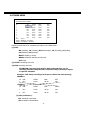
3.9 HDD (harddisk) MENU
DISK SETUP MENU
DISK INFORMATION
DISK VIDEO DELETE
THERMOMETRIC SCALE
NO.
01
SIZE(GB) °C
152
42
02
152
03
04
NO EXIST
NO EXIST
43
1-4
01
CELSIUS
START/END TIME
13.11.2005 14:55:45
15.11.2005 16:59:40
15.11.2005 16:59:40
16.11.2005 09:23:11
PRESS SELECT/MIDDLE TO START DELETE
Check harddisk status and delete harddisk indexes in the HDD menu.
(1) DISK INFORMATION: Harddisk number in blocks of 4 HDD (more than 2 HDD only in
combination with harddisk expansion EDA800), use the JOG for selection
(2) DISK VIDEO DELETE: After confirmation with SELECT and a further security request, the
harddisk’s index is deleted.
ATTENTION: Deleting the index does not comprise the secure erasure of video
data in terms of data protection. The secure erasure is not possible in the DVR,
but on a PC, requiring a specific tool provided by the HDD manufacturer!
(3) THERMOMETRIC SCALE: Select the temperature unit °CELSIUS or °FAHRENHEIT for
display of the current HDD temperature.
(4) TABLE:
SIZE(GB): Total HDD capacity in Gigabyte
°C (or °F): current HDD temperature, readout through the HDD S.M.A.R.T. interface
The temperature is readout cyclically. After restarting the recording, allow some
minutes for initial temperature display.
START/END TIME: Time and date of the first and last recording available on the
HDD.
47
3.10 RS232/RS485 MENU
CONTROL SETUP MENU
RS232
BAUD RATE
STOP BIT
PARITY
DATA BIT
9600 BPS
1
NONE
8
RS485
BAUD RATE
STOP BIT
PARITY
DATA BIT
9600 BPS
1
NONE
8
RS232/RS485 ID
1
PTZ PROTOCOL
EVERFOCUS
Define the settings for DVR remote control through serial interface in the RS232/RS485
menu. Pin assignment and remote control protocol are described in appendix B and C.
(1) RS232 BAUD RATE: RS-232 interface transmission speed. 1200, 2400, 4800, 9600, 19200
and 3840 baud can be selected.
Default setting: 9600 baud
(2) RS232 STOP BIT:
Number of stop bits: 1 or 2
(3) RS232 PARITY:
Parity mode: NONE / EVEN / ODD
(4) RS232 DATA BIT:
Number of data bits: 8 or 7
(5) RS485 BAUD RATE: RS-485 interface transmission speed. 1200, 2400, 4800, 9600, 19200
and 3840 baud can be selected.
Default setting: 9600 baud
(6) RS485 STOP BIT:
Number of stop bits: 1 or 2
(7) RS485 PARITY:
Parity mode: NONE / EVEN / ODD
(8) RS485 DATA BIT:
Number of data bits: 8 or 7
(9) RS232/RS485 ID:
RS232/RS485 address. Addressable range: 1~255.
This address complies with the device number for remote control
through keyboards EKB 500, KS KBK and KS KBJ (DEVICE No.).
(10) PTZ-PROTOCOL:
Protocol type setting for network telemetry control, available protocols:
EVERFOCUS1 (EPTZ1800 Dome),
EVERFOCUS2 (EPTZ1000/3000 Dome),
ED2200/2250 (complies with Samsung protocol SCC-641/643),
Pelco-D, Pelco-P
NOTE: Standard setting for EKB500 keyboard connection:
RS-485 Baud Rate: 9600, 1 stop bit, Parity NONE, RS232/RS485 ID = Device/DVR
Nr. at keyboard
48
3.11 WARNING MENU
The EDR provides warning functions allowing signalling upon operation failure. Define the
alarm reactions in the WARNING menu.
3.11.1 FAN FAILURE
WARNING SETUP MENU
FAN FAULT
HDD TEMP.
NO HDD
HDD FULL
BUZZER
ALARM OUTPUT
ALARM DURATION
NETWORK ALARM
EMAIL
ENABLE
1
PERMANENT
NO
NO
Both fans provide failure detection. Define the alarm reactions upon fan failure in this menu
item:
(1)BUZZER: By selection “ENABLE”, the buzzer is activated upon fan failure.
(2)ALARM OUTPUT: Output relay activation.
1 – Output relay 1 (for EDR410/810, only one output relay is available)
NONE – no relay reaction upon alarm.
(3) ALARM DURATION: PERMANENT - This value cannot be changed, alarm is
automatically switched off after problem has been solved
(fan replacement).
(4) NETWORK ALARM:
YES: Network alarm activated (for settings refer to NETWORK menu)
Network alarm reception requires optional PowerCon software.
NO: No network alarm transmission
(5) EMAIL:
YES: Alarm email transmission (for settings refer to NETWORK menu).
NO: No email alarm transmission.
49
3.11.2 HDD TEMP.
WARNING SETUP MENU
FAN FAULT
HDD TEMP.
NO HDD
HDD FULL
BUZZER
ALARM OUTPUT
ALARM DURATION
NETWORK ALARM
EMAIL
STOP RECORD
ENABLE
1
PERMANENT
NO
NO
YES
The enduring HDD temperature surveillance guarantees an alarm reaction in case the
threshold value is exceeded.
There may be several reasons for HDD temperature excess:
- Exceedance of the max. tolerable ambient temperature (40°C), e.g. upon installation in
an electrical cabinet with inadequate ventilation
- After-effect upon fan failure
- HDD defect
(1) BUZZER:
By selecting “ENABLE”, the buzzer is activated upon HDD temperature excess.
(2) ALARM OUTPUT: Output relay activation.
1 – Output relay 1 ~ 4 (selection) switches upon alarm.
NONE – no output relay reaction upon alarm.
(3) ALARM DURATION: PERMANENT - This value cannot be changed, alarm is
automatically switched off after problem has been solved.
(4) NETWORK ALARM:
YES: Network alarm activated (for settings refer to NETWORK menu)
Network alarm reception requires optional PowerCon software.
NO: No network alarm transmission
(5) EMAIL:
YES: Alarm email transmission (for settings refer to NETWORK menu).
NO: No email alarm transmission.
(6) STOP RECORD
YES: Recording process is stopped to avoid further temperature rise
and HDD damage.
NO: Recording process continues.
50
3.11.3 NO HDD
WARNING SETUP MENU
FAN FAULT
HDD TEMP.
NO HDD
HDD FULL
BUZZER
ALARM OUTPUT
ALARM DURATION
NETWORK ALARM
EMAIL
ENABLE
1
PERMANENT
NO
NO
The DVR detects when both harddisks are removed, switched off or not detected. Define the
alarm reactions in this menu item:
(1) BUZZER:
By selecting “ENABLE”, the buzzer is activated.
(2) ALARM OUTPUT: Output relay activation.
1 – Output relay 1 ~ 4 (selection) switches upon alarm.
NONE – no output relay reaction upon alarm.
(3) ALARM DURATION: Alarm duration adjustment from 1~99 seconds or permanent.
(4) NETWORK ALARM:
YES: Network alarm activated (for settings refer to NETWORK menu)
Network alarm reception requires optional PowerCon software.
NO: No network alarm transmission
(5)
EMAIL:
YES: Alarm email transmission (for settings refer to NETWORK menu).
NO: No email alarm transmission.
51
3.11.4 HDD FULL
WARNING SETUP MENU
FAN FAULT
HDD TEMP.
NO HDD
HDD FULL
BUZZER
ALARM OUTPUT
ALARM DURATION
NETWORK ALARM
EMAIL
ENABLE
1
PERMANENT
NO
NO
In operation mode HDD FULL: STOP (setting in RECORDING menu), the recording
process is stopped if the harddisk is full. Define the alarm reactions in this menu item:
(1)BUZZER:
By selecting “ENABLE”, the buzzer is activated.
(2)ALARM OUTPUT: Output relay activation.
1 – Output relay 1 ~ 4 (selection) switches upon alarm.
NONE – no output relay reaction upon alarm.
(3) ALARM DURATION: Alarm duration adjustment from 1~99 seconds or permanent
(4) NETWORK ALARM:
YES: Network alarm activated (for settings refer to NETWORK
menu)
Network alarm reception requires optional PowerCon software.
NO: No network alarm transmission
(5)
menu).
EMAIL:
YES: Alarm email transmission (for settings refer to NETWORK
NO: No email alarm transmission.
52
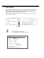
3.12 SYSTEM MENU
SYSTEM SETUP MENU
SYSTEM VERSION
SYSTEM VIDEO FORMAT
V1.22
PAL
LOAD/SAVE CONFIGURATION
NO
UPDATE SYSTEM SOFTWARE
NO
LANGUAGE
ENGLISH
QUICK PLAY
ON 10 MINUTES AGO
SYSTEM PASSWORD ENABLE
LEVEL-3
LEVEL-2
LEVEL-1
PASSWORD
*************
*************
*************
NO
RIGHTS
ADMINISTRATOR
OPERATOR
GENERAL
Define the following settings in the SYSTEM menu:
(1) SYSTEM VERSION: Display of the installed firmware version.
(2) SYSTEM VIDEO FORMAT: Display of the detected video system PAL or NTSC. The EDR
automatically detects the video system upon system startup.
ATTENTION: Auto detection checks video input 1 upon system startup.
Therefore, it is compulsory to start the DVR with video signal connected to
channel 1. Otherwise, default setting NTSC is loaded!
(3) SAVE/LOAD CONFIGURATION:
Selecting YES opens a sub menu showing the following items (use the JOG
for selection):
CANCEL: Return to system menu
DEFAULT: Load default setting after security request YES/NO
ATTENTION: The network settings remain stored despite loading default setting!
SAVE: Save the current configuration to CF card / USB stick.
LOAD: Load a configuration from CF card / USB stick.
(4) UPDATE SYSTEM SOFTWARE: DVR update with latest firmware version through USB-stick
or CF card. At first, place the CF card or the USB stick into the respective
interface.
YES: After confirmation with SELECT, the firmware update is run. Update is
carried out in 3 phases (display at bottom screen margin) and can take up to
5 minutes.
ATTENTION:
1. Before starting the update, stop the recording process.
2. Do not switch the DVR off while update is run.
3. Do not remove CF card or USB stick while update is run.
NO: Cancel, return to SYSTEM menu
53
ATTENTION: After updating the system, restart, loading of default settings and further restart are
required. Furthermore, HDD should be deleted.
(5) LANGUAGE: System language selection.
(6) QUICK PLAY: The "QuickPlay" function is a convenient playback function allowing the immediate
playback of video recorded 5~60 minutes ago by pressing the PLAY key.
ON: QuickPlay function activated.
OFF: QuickPlay function deactivated. Pressing the PLAY key starts the playback at
the last playback position.
xx MINUTES AGO: Enter the time in minutes, adjustable from 5~60 minutes.
ATTENTION: If the DVR operates with low recording rates, the playback may overlap into the
active (not yet closed) recording segment in case the QuickPlay time is not long enough,
resulting in black images and the message “????” in the status bar.
If this happens, choose a longer QuickPlay time.
(7) SYSTEM PASSWORD:
By selecting “ENABLE”, different EDR operations require password input for local use.
3 different levels of user rights are available. Passwords can be modified in the list.
Default settings are:
Level 1: 111111
Level 2: 222222
Level 3: 333333
ATTENTION: If a password applies to different levels, login is carried out in the higher level.
54
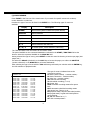
User rights, version 1.22
LEVEL
RIGHT
DISPLAY
MODE
ZOOM
FULL
SELECT
SEQ
CALL
MENU
COPY
SEARCH
PLAY
STOP
REV.PLAY
REC
PAUSE
LEVEL-3
ADMINISTRATOR
OK
OK
OK
OK
OK
OK
OK
OK
OK
OK
OK
OK
OK
OK
OK
LEVEL-2
OPERATOR
OK
OK
OK
OK
OK
OK
OK
NO
NO
NO
NO
NO
NO
NO
NO
55
LEVEL-1
GENERAL
OK
OK
OK
OK
OK
OK
NO
NO
NO
NO
NO
NO
NO
NO
NO
WITHOUT
---OK
OK
OK
OK
NO
NO
NO
NO
NO
NO
NO
NO
NO
NO
NO
4. RECORDING
4.1 RECORDING
ATTENTION: The following instructions as regard to the EDR DVR recording and recording
standby have to be followed thoroughfully. Some of the DVR’s functions
significantly differ from previous models.
REC
Actuate the REC key to switch the DVR to recording resp. recording standby mode.
The red LED within the REC key is illuminated.
Alternatively, the DVR can be switched to recording / recording standby mode
through the REC IN input contact.
ATTENTION: The DVR must be switched to recording standby mode (LED in REC
key ON!), even if only motion- or alarm-triggered recording is selected (no
continuous recording), otherwise no recording will be processed!
This doesn’t apply to scheduled recordings (TIMER) which switch to recording
mode even if recording standby mode is switched off.
Press the STOP key to stop the recording resp. recording standby.
• To stop scheduled recordings, the timer must be deactivated in the
TIMER menu.
STOP
• First STOP key actuation in playback mode stops the playback,
second actuation stops the recording resp. recording standby.
ATTENTION: HDD shutdown and removal is not admissable during recording and playback mode
and upon DVR system startup!
ATTENTION: Switching off the harddisk with the key switch will logoff the harddisk from the system.
Remove the harddisk only after the green power source LED at the harddisk tray is extinguished.
56
4.2 TIMER – scheduled recording
Define the scheduled recording settings in the TIMER menu.
With activated timer, recording starts and stops automatically.
4.3 Event recording
If event-triggered recordings are programmed in the ALARM and/or MOTION menu, the
respective cameras are recorded at the “EVENT” recording rate (programming in CAMERA
menu).
ATTENTION:
For this recording mode, the DVR must be in recording standby mode (REC-LED ON).
The DVR can be switched to standby mode either manually (through REC key), via TIMER
configuration or through the REC-IN contact.
ATTENTION: HDD shutdown and removal is not admissable during recording and playback mode
and upon DVR system startup!
ATTENTION: Switching off the harddisk with the key switch will logoff the harddisk from the system.
Remove the harddisk only after the green power source LED at the harddisk tray is extinguished.
57
5. PLAYBACK
5.1 PLAYBACK WITHOUT SEARCH FUNCTION
(1) Playback
Press the PLAY key to switch the DVR to playback mode. Depending on
the “QuickPlay” function settings (see SYSTEM menu), playback starts at
one of the following positions:
QuickPlay OFF: playback starts at the last playback position
PLAY
QuickPlay ON: playback starts 5 ~ 60 min (definition in SYSTEM menu)
before current recording position
(2) STOP
Press the STOP key to stop the playback mode.
STOP
(3) Fast forward / reverse
Use the JOG/SHUTTLE to control the playback speed in playback mode.
PLAY
Turn the SHUTTLE clockwise for fast forward playback. Depending on the
shuttle speed, the playback speed increases to 2, 4, 6, 8, 16 or 32x.
Turn the SHUTTLE counter-clockwise for normal or fast reverse playback.
Depending on the shuttle speed, the playback speed increases to 2, 4, 6, 8,
16 or 32x.
Use the ENTER key to lock the fast playback search and the SHUTTLE or
PLAY key to unlock the fast playback search.
ATTENTION: HDD shutdown and removal is not admissable during recording and playback mode
and upon DVR system startup!
ATTENTION: Switching off the harddisk with the key switch will logoff the harddisk from the system.
Remove the harddisk only after the green power source LED at the harddisk tray is extinguished.
58
(4) Slow forward playback
PAUSE
Press the PAUSE key during playback to freeze the image at the current
playback position.
Turn the SHUTTLE clockwise for slow forward playback. Depending on the
shuttle speed, the playback speed is reduced to 1/2, 1/4, 1/8, 1/10, 1/16, 1/32 of
the normal speed.
This playback mode is not available for reverse playback.
(4) Single image playback
Press the PAUSE key during playback.
Turn the JOG for single image playback. Increasing the rotational speed will
increase the playback speed.
ATTENTION: Upon simultaneous playback and recording, first actuation of the STOP
key will stop the playback, second actuation will stop the recording.
ATTENTION: HDD shutdown and removal is not admissable during recording and playback mode
and upon DVR system startup!
ATTENTION: Switching off the harddisk with the key switch will logoff the harddisk from the system.
Remove the harddisk only after the green power source LED at the harddisk tray is extinguished.
59
5.2 PLAYBACK SEARCH
Press the SEARCH key to enter the search menu.
SEARCH
NAVIGATION:
Use the JOG to select values or entries.
Use the ENTER key to go to the next menu item and the DISPLAY key
to go to the previous menu item.
Press the SELECT key to confirm a selection.
Press the MENU key to leave the search menu.
(1) TIME / DATE SEARCH
Select TIME/DATE in the first row of the search menu to enter the requested playback position
in the following rows.
The period available on the connected harddisks is indicated in the START/END TIME field.
Select the respective harddisk in the DISK NO field.
SEARCH MENU
METHOD
TIME / DATE
DATE
TIME
11-09-2005 FR
00:33:23
EVENT
A/M/V
DISK NO
01
NO
01
SIZE(GB) °C
152
42
START / END TIME
10-09-2005 07:33:23
14-09-2005 06:53:11
The values in the EVENT row cannot be changed upon time/date search.
The bottom table further shows the total capacity of the used harddisk, its current
temperature and the timeframe of available recordings.
ATTENTION: When searching for a playback position just before current recording position,
it may occur that this position isn’t available for playback yet (in case the recording segment
hasn’t been closed yet). Playback then starts at the next possible position.
60
(2) EVENT SEARCH
Enter EVENT in the first row of the search menu if you search for specific events such as alarm,
motion detection or video loss.
Preselect the type of event to be listed in the EVENT row. The following types of event are
available:
Display
Description
ALARM
Alarm events (alarm contacts and system alarms)
MOTION
Motion detection
VLOSS
Video loss
A/B
Alarm and motion detection
A/V
Alarm and video loss
B/V
Motion detection and video loss
A/B/V
All events (alarm, motion detection, video loss)
The TIME and DATE rows are inactive for this search mode.
The period available on the connected harddisks is indicated in the START / END TIME field at the
bottom. Select the requested harddisk in the DISK NO field.
Having selected the type of event, press SELECT to start the event list showing 16 entries per page (640
pages max.).
Use either the Shuttle (clockwise) or the COPY key to browse the pages; use either the SHUTTLE
(counter-clockwise) or the DISPLAY key to browse backwards.
After selecting the type of event with the JOG and having confirmed your selection with the ENTER key,
the DVR switches to playback mode.
The type of event is indicated next to the
consecutive number:
A: Alarm (Alarm contact) + contact number;
M: Motion detection + camera number;
V: Video loss + camera number;
TN: Start normal recording;
Tn: Scheduled recording, n=1~8;
PL: Power loss;
RTN: Automatic recording restart after power
loss;
RTn: Automatic scheduled recording restart
after power loss, Timer n=1~8.
PH (Physical Head): Physical HDD initial position;
LH (Logical Head): Logical HDD initial position
upon rewriting.
F1, F2: Fan failure fan 1 / 2
OT: HDD overtemperature
SEARCH LIST
00001
00002
00003
00004
00005
00006
00007
00008
00009
00010
00011
00012
00013
00014
00015
00016
M08
M01
M08
M04
M08
M03
V01
TN
M01
M03
M03
M04
M08
M01
M01
M08
10-09-2005
10-09-2005
10-09-2005
10-09-2005
10-09-2005
10-09-2005
10-09-2005
10-09-2005
10-09-2005
10-09-2005
10-09-2005
10-09-2005
10-09-2005
10-09-2005
10-09-2005
10-09-2005
10:11:33
12:13:34
12:13:39
10:14:55
10:15:33
10:23:34
10:22:12
10:50:45
10:54:35
11:13:35
11:15:24
11:18:37
12:11:34
13:33:25
14:09:11
15:11:27
61
6. VIDEO EXPORT
Video data can be exported as *.arv format movie file to both a USB stick or the external USB
DVD drive EPR200. PC playback requires the dedicated viewer software which may be copied to
USB stick through the COPY menu described below or which can be downloaded via the
browser web applet in case a network connection is provided.
Single *.jpg format images can be created with the EDR viewer software. A direct single image
export from EDR is not supported.
USB socket
Insert the CF card resp. the USB stick.
Press the COPY key to open the video export menu.
COPY
COPY MENU
COPY
DISK NO
VIDEO
01
START DATE
TIME
10-09-2005 FR
12:22:34
END DATE
TIME
10-09-2005 FR
12:27:34
NO
01
SIZE(GB) °C
152
42
CAMERA NO 04
START/END TIME
10-09-2005 07:33:23
14-09-2005 06:53:11
PRESS MENU TO EXIT
PRESS SELECT/MIDDLE TO START COPY
62
Define the following settings in the COPY menu:
COPY:
Select “VIDEO” to export video data.
Select “VIEWER” to copy the EDR viewer playback software.
DISK NO:
Harddisk number; the respective harddisk’s recording timeframes
are indicated in the bottom list.
CAMERA NO:
Number of the camera channel from which the video is to be exported.
START DATE / TIME: Video export start position.
END DATE / TIME: Video export final position.
ATTENTION: The video export start position can also be selected by
pressing the COPY key during playback.
The buffered time is automatically transferred as start time in the COPY
menu, the end time is automatically defined as START TIME + 5 minutes.
Both values can be changed manually.
Having selected the camera number and start / end time, start the export by pressing the
SELECT key.
63
7. CALL / MATRIX MONITOR SETUP
Enter the call and matrix monitor setup menu by pressing the CALL key:
CALL MENU
MONITOR
CALL MON
MATRIX MON 1
MATRIX MON 2
MATRIX MON 3
MATRIX MON 4
SEQ
OFF
OFF
OFF
OFF
OFF
OSD
ON
ON
ON
ON
ON
CAMERA
01
01
01
01
01
PRESS SEQ/MIDDLE TO ON/OFF SEQ
PRESS DISPLAY TO ON/OFF OSD
PRESS CHANNEL NO/WHEEL TO SET CAMERA
Define the following settings in the CALL menu:
Press ENTER to select the respective monitor and the selection options:
(1) SEQ:
“ON" activates the monitor’s sequence mode (automatic sequential switch).
(2) OSD:
“ON" activates the monitor’s status display including camera number,
monitor number and active alarms for this monitor.
(3) CAMERA:
Select the camera to be displayed with the channel keys 1~9 (EDR920) resp.
1~16 (EDR1640).
64
8. DISPLAY SETTINGS
8.1. BRIGHTNESS, CONTRAST, COLOUR
Press SELECT to adjust brightness, contrast and colour for each video channel in full screen
mode of the respective camera (channel keys 1 ~ 9 resp. 1 ~ 16):
Press ENTER to switch between the settings and use the JOG to adjust the values on the
slidebars.
(1) BRIGHTNESS:
Adjust the image brightness from 0 ~ 100%.
(2) CONTRAST:
Adjust the image contrast from 0 ~ 100%.
(3) COLOUR:
Adjust the colour saturation from 0 ~ 100%.
The current value is indicated both on the slidebar and as percentage.
Press MENU or SELECT to leave the menu.
8.2 IMAGE POSITION ADJUSTMENT ON MONITOR
If the monitor display is not centre positioned, the horizontal and vertical image position can be
adjusted.
Press the ZOOM key in any multiscreen display (not full screen mode).
Use the JOG to horizontally centre the image position and press ENTER to switch to vertical
direction.
Further ZOOM key actuation switches the adjustment off.
65
9. SCREEN DISPLAY
Press the MODE key to switch between 4x, 7x, 9x, 10x, 13x, 16x and PiP (Picture-in-Picture)
main monitor display. 10x, 13x and 16x display are available for EDR1640 only.
66
10. EDA 966 INFRARED REMOTE CONTROL (optional)
The optional EDA966 IR remote control allows the EDR remote control covering a maximum
distance of 10m.
Basically, the keys comply with the EDR DVR front panel keys.
Key assignment differing to EDR front panel:
JOG
: JOG clockwise.
JOG
: JOG counter-clockwise.
SHUTTLE
1: 2x fast search or 1/2x slow search (in PAUSE)
2: 4x fast search or 1/4x slow search (in PAUSE)
3: 8x fast search or 1/8x slow search (in PAUSE)
4: 16x fast search or 1/10x slow search (in PAUSE)
5: 32x fast search or 1/16x slow search (in PAUSE) .
SHUTTLE
1: 2x reverse search
2: 4x reverse search
3: 8x reverse search
4: 16x reverse search
5: 32x reverse search
NOTE: Keys 10~16 are active for EDR1640 only.
67
11. NETWORK ACCESS
PC SYSTEM REQUIREMENTS:
Operating system Windows XP SP2 / Windows 2000 SP6, DirectX 9.0c, Internet Explorer min. 6.x.
ActiveX applications must be permitted in the Internet Explorer settings.
The loading and installation of ActiveX components during initial installation require local PC
administration rights.
The following elaborations assume the proper DVR network connection installation.
ACCESS VIA INTERNET EXPLORER
Enter the DVR IP address in the Internet Explorer address line:
Enter user name and password in the LOGIN screen.
68
SCREEN ELEMENTS
17
7
8
9
16
10
11
12
14
13
15
1
2
3 4 5 6
The illustration shows the screen user interface with the following icons and operating elements:
1.
REVERSE PLAYBACK
2.
STOP: Stop playback mode and switch to live mode.
3.
PLAYBACK
4.
SINGLE IMAGE FORWARD: Switch to next image in PAUSE mode.
5.
PAUSE: Stop playback, freeze image.
6.
SINGLE IMAGE REVERSE: Switch to previous image in PAUSE mode.
7.
8.
9.
10.
11.
12.
13.
14.
15.
16.
Playback search, PTZ control
Types of event
Event list
Play start event playback
Update start / refresh event list
Connection status (PLAY or LIVE), in playback mode: playback position indication
Full screen display
4x screen display (quad)
9x screen display
Click right into a camera screen to open the context menu showing a list of all
cameras available
Download EDR viewer software for export file playback (click in logo)
17.
69
PLAYBACK SEARCH
Select search mode either by time/date or by event list.
Event list search mode
Select the types of event to be displayed: ALARM, MOTION (motion detection), VLOSS
(video loss).
Press UPDATE to start / refresh the event list.
The load time depends on both the event list size and the network speed.
Events are displayed with type of event, time and date indication.
The number of pages available (max. 640) is indicated below the list. Use the following keys
to browse the pages:
>> next page,
<< previous page,
>>| last page,
|<< first page.
Alternatively, the page number can also be entered directly, press GO to switch to the
selected page.
Press PLAY to start the playback after selecting an entry.
70
TIME / DATE SEARCH
Year
Month
Day
Second
Minute
Hour
Selecting "Search by Time" opens an entry mask for playback position date and time input.
Press the PLAY key to start the playback after data input.
71
PTZ CONTROL
The EDR DVR allows the speed dome and PTZ device control via network.
Select “PTZ CONTROL” to activate the telemetry mode.
Select the camera in the PTZ CAM field.
The following control functions are available:
1. Camera selection
2. Key mode:
Pan/tilt/zoom key reaction type
Continuous – control command is sent continuously
Step x 10 – 10 single commands per keystroke are sent
Step x 5 - 5 single commands per keystroke are sent
Step x 1 – 1 single command per keystroke is sent
3. Directional arrows: Pan / tilt control keys
4. Z+ / Z-:
Zoom function Z+: Tele, Z-: Wide
5. Focus:
manual focus
NEAR: near range,
FAR: tele range
6. IRIS:
manual iris control
OPEN: open iris
CLOSE: close iris
7. PRESET:
Preset selection
SET: Save current PTZ position as selected preset number
CLR: Delete the selected preset position
JUMP: Approach the selected preset position
8. AUTO PAN:
Automatic pan function
RUN:
start AUTO PAN
STOP:
stop AUTO PAN
72
APPENDIX A: EDR VIEWER SOFTWARE
APPENDIX A: EDR VIEWER SOFTWARE
EDR video data exported with the COPY function are saved as *.arv files, an MPEG-4 file
format which cannot be run with common software, but requires a special viewer
software.
This „EDR viewer“ software (freeware, no licensing required) is available in the DVR
memory and may be copied anytime by one of the following methods:
1. Export to USB stick: Select „VIEWER“ in the first row of the COPY menu. Press the
SELECT key to copy the software to the inserted USB stick.
2. Download via network: If the DVR is connected to a PC via network, the EDR viewer
software can also bei downloaded via Internet Explorer. Click the EverFocus logo to
start the download.
73
APPENDIX A: EDR VIEWER SOFTWARE
EDR VIEWER INSTALLATION
PC SYSTEM REQUIREMENTS:
Operating system Windows XP SP2 / Windows 2000 SP6, DirectX 9.0c (free download on
www.microsoft.com/directx), Internet Explorer min. 6.x, DivX codec (for AVI export, free
download on e.g. www.divx.com).
The EDR viewer consists of one file only: EDRViewer.exe. Save this file to your PC and run
the exe file.
The EDR viewer enables ARV file playback, JPG format single image storage and video file
conversion to AVI format (with DivX codec, see PC SYSTEM REQUIREMENTS).
ATTENTION: The conversion of video files recorded with 720x288 recording resolution will
result in AVI files with half the image height. For these files, it is recommended to make use of
playback software able to correct the aspect ratio (e.g. MediaPlayer Classic, freeware, download
on www.everfocus.de).
74
APPENDIX B: Interface specification
INTERFACE SPECIFICATION
1. RS-232 Pin assignment
EDR1640/920 can be controlled by external devices through RS-232 interface.
Pin assignment 9-pin RS-232 plug
1 2 3 4 5
6 7 8 9
HOST
DVR
PIN
1
2
3
4
5
6
7
8
9
NAME
FREE
TXD
RXD
FREE
SIGNAL GROUND
FREE
FREE
FREE
FREE
PIN #
NAME
1
FREE
2
RXD
3
TXD
4
FREE
5
SIGNAL GROUND
6
FREE
7
FREE
8
FREE
9
FREE
RS-485 pin assignment
Both RS-485 sockets are equally wired.
1 2 3 4 5 6 7 8
Pin 1: GND
Pin 3: RS485 + (A)
Pin 6: RS485 - (B)
Illustration: contact side RJ-45 plug
2. Interface settings
For the RS232/485 port, 6 different speeds are available: 1200, 2400, 4800, 9600, 19200 and
38400 baud. Define the port settings in the RS232/RS485 menu.
75
APPENDIX C: Remote control protocol
3. Remote control protocol
The following remote control protocol applies to RS232 and RS485 remote control. The
EEPBus protocol is a universal control protocol for EDSR and EDR (MPEG4) series’ digital video
recorders. Therefore, it may occur that some of the following commands are not available for
all DVR types.
1-1. Sample control code packets
Example 1 : A packet that sends "REC" key to DVR (ID=5)
0x85
(length)
0x00
(Receiver ID high byte)
0x05
(Receiver ID low byte)
0x4B
(OPcode = key )
0x08
(DATA1 = "Rec" keycode )
0x5D
(checksum)
Example 2 : A packet that sends "PAUSE" key to DVR (ID=4999)
0x85
(length)
0x27
(Receiver ID high byte)
0x07
(Receiver ID low byte)
0x4B
(OPcode = key )
0x0C
(DATA1 = "Pause" keycode )
0x0A
(checksum)
Example3 : A packet that sends "PLAY" key to all DVR (broadcast)
0x85
(length)
0x7f
(Receiver ID high byte)
0x7f
(Receiver ID low byte)
0x4B
(OPcode = key )
0x0B
(DATA1 = "Play" keycode )
0x59
(checksum)
76
APPENDIX C: Remote control protocol
2-1. The format of message packet is as follows:
Length Byte (Prefix: 0x86, 0x87, or 0x88 ..... )
Receiver ID high byte
Receiver ID low byte
Opcode Byte
Data Byte1
Data Byte2
Data Byte3
Checksum Byte
2-2. Length Byte
This Length Byte is also a prefix. Bit7 must be 1.
EX:
0x87 ==> this packet has 7 bytes length. (not included length byte itself )
77
APPENDIX C: Remote control protocol
2-3. Receiver ID
1.) Individual receiver ID
Decimal
14bit binary value
Hbyte
Lbyte
Receiver ID (EDSR)
0
0000000 0000000
00
00
ID = 0
1
0000000 0000001
00
01
ID = 1
2
0000000 0000010
00
02
ID = 2
126
0000000 1111110
00
7e
ID = 126
127
0000000 1111111
00
7f
ID = 127
128
0000001 0000000
01
00
ID = 128
129
0000001 0000001
01
01
ID = 129
255
0000001 1111111
01
7f
ID = 255
256
0000010 0000000
02
00
ID = 256
0000011 1111111
03
7f
ID = 511
1111111 1111110
7f
7e
ID = 16382
....
....
511
....
16382
2.) Broadcast ID
Decimal
14bit binary value
Hbyte
Lbyte
Receiver ID
16383
1111111 1111111
7f
7f
all DVR
connect to RS485/RS232
78
APPENDIX C: Remote control protocol
2-4. Opcode Byte & Data bytes
2-4-1. OPcode
OPcode
Data1
Function
0x4B
Keycode
A remote key pressed
0x4D
command
Matrix command
2-4-2. Remote keys (OPcode=0x4B)
---------------------------------------------------------------------------------------------------Data1 Key
Data1 Key
0x1e JOG<
0x00
CH1
0x01
CH2
0x1f
JOG>
0x02
CH3
0x20
CH5
0x03
CH4
0x21
CH6
0x04
MODE
0x22
CH7
0x05
ZOOM
0x23
CH8
0x06
SEQ
0x24
CH9
0x07
MENU
0x25
CH10
0x08
REC
0x26
CH11
0x09
REV.PLAY
0x27
CH12
0x0A
STOP
0x28
CH13
0x0B
PLAY
0x29
CH14
0x0C
PAUSE
0x2a
CH15
0x0D
SEARCH
0x2b
CH16
0x0E
COPY
0x2c
SELECT
0x0F
DISPALY
0x2d
CALL
0x10
SHUTTLE<<x1
0x2e
ENTER
0x11
SHUTTLE<<x2
0x2f
(reserve)
0x12
SHUTTLE<<x4
0x30
(reserve)
0x13
SHUTTLE<<x8
0x31
(reserve)
0x14
SHUTTLE<<x16
0x32
(reserve)
0x15
SHUTTLE<<x32
0x33
(reserve)
0x16
SHUTTLE<<x600
0x34
(reserve)
0x17
SHUTTLE>>x1
0x18
SHUTTLE>>x2
0x19
SHUTTLE>>x4
0x1a
SHUTTLE>>x8
0x1b
SHUTTLE>>x16
0x1c
SHUTTLE>>x32
0x1d
SHUTTLE>>x600
79
APPENDIX C: Remote control protocol
2-4-3. Matrix command
(OPcode=0x4D)
Data1
Matrix function
Data1
Matrix function
Data1
Matrix function
0x00
Matrix monitor0 - ch01 spot
0x21
Matrix monitor2 - ch02 spot
0x42
Matrix monitor4 - ch03 spot
0x01
Matrix monitor0 - ch02 spot
0x22
Matrix monitor2 - ch03 spot
0x43
Matrix monitor4 - ch04 spot
0x02
Matrix monitor0 - ch03 spot
0x23
Matrix monitor2 - ch04 spot
0x44
Matrix monitor4 - ch05 spot
Matrix monitor4 - ch06 spot
0x03
Matrix monitor0 - ch04 spot
0x24
Matrix monitor2 - ch05 spot
0x45
0x04
Matrix monitor0 - ch05 spot
0x25
Matrix monitor2 - ch06 spot
0x46
Matrix monitor4 - ch07 spot
0x05
Matrix monitor0 - ch06 spot
0x26
Matrix monitor2 - ch07 spot
0x47
Matrix monitor4 - ch08 spot
0x06
Matrix monitor0 - ch07 spot
0x27
Matrix monitor2 - ch08 spot
0x48
Matrix monitor4 - ch09 spot
0x07
Matrix monitor0 - ch08 spot
0x28
Matrix monitor2 - ch09 spot
0x49
Matrix monitor4 - ch10 spot
Matrix monitor4 - ch11 spot
Matrix monitor0 - ch09 spot
0x29
Matrix monitor2 - ch10 spot
0x4a
0x09
Matrix monitor0 - ch10 spot
0x2a
Matrix monitor2 - ch11 spot
0x4b
Matrix monitor4 - ch12 spot
0x0a
Matrix monitor0 - ch11 spot
0x2b
Matrix monitor2 - ch12 spot
0x4c
Matrix monitor4 - ch13 spot
Matrix monitor4 - ch14 spot
0x08
0x0b
Matrix monitor0 - ch12 spot
0x2c
Matrix monitor2 - ch13 spot
0x4d
0x0c
Matrix monitor0 - ch13 spot
0x2d
Matrix monitor2 - ch14 spot
0x4e
Matrix monitor4 - ch15 spot
0x0d
Matrix monitor0 - ch14 spot
0x2e
Matrix monitor2 - ch15 spot
0x4f
Matrix monitor4 - ch16 spot
0x0e
Matrix monitor0 - ch15 spot
0x2f
Matrix monitor2 - ch16 spot
0x50
Matrix monitor0 - sequence
0x0f
Matrix monitor0 - ch16 spot
0x30
Matrix monitor3 - ch01 spot
0x51
Matrix monitor1 - sequence
Matrix monitor2 - sequence
Matrix monitor3 - sequence
0x10
Matrix monitor1 - ch01 spot
0x31
Matrix monitor3 - ch02 spot
0x52
0x11
Matrix monitor1 - ch02 spot
0x32
Matrix monitor3 - ch03 spot
0x53
0x12
Matrix monitor1 - ch03 spot
0x33
Matrix monitor3 - ch04 spot
0x54
Matrix monitor4 - sequence
Matrix monitor0 - turn OSD on
Matrix monitor1 - ch04 spot
0x34
Matrix monitor3 - ch05 spot
0x60
0x14
Matrix monitor1 - ch05 spot
0x35
Matrix monitor3 - ch06 spot
0x61
Matrix monitor1 - turn OSD on
0x15
Matrix monitor1 - ch06 spot
0x36
Matrix monitor3 - ch07 spot
0x62
Matrix monitor2 - turn OSD on
0x16
Matrix monitor1 - ch07 spot
0x37
Matrix monitor3 - ch08 spot
0x63
Matrix monitor3 - turn OSD on
0x17
Matrix monitor1 - ch08 spot
0x38
Matrix monitor3 - ch09 spot
0x64
Matrix monitor4 - turn OSD on
Matrix monitor0 - turn OSD off
0x13
0x18
Matrix monitor1 - ch09 spot
0x39
Matrix monitor3 - ch10 spot
0x70
0x19
Matrix monitor1 - ch10 spot
0x3a
Matrix monitor3 - ch11 spot
0x71
Matrix monitor1 - turn OSD off
0x1a
Matrix monitor1 - ch11 spot
0x3b
Matrix monitor3 - ch12 spot
0x72
Matrix monitor2 - turn OSD off
Matrix monitor3 - turn OSD off
Matrix monitor4 – turn OSD off
0x1b
Matrix monitor1 - ch12 spot
0x3c
Matrix monitor3 - ch13 spot
0x73
0x1c
Matrix monitor1 - ch13 spot
0x3d
Matrix monitor3 - ch14 spot
0x74
0x1d
Matrix monitor1 - ch14 spot
0x3e
Matrix monitor3 - ch15 spot
0x1e
Matrix monitor1 - ch15 spot
0x3f
Matrix monitor3 - ch16 spot
0x1f
Matrix monitor1 - ch16 spoz
0x40
Matrix monitor4 - ch01 spot
0x20
Matrix monitor2 - ch01 spot
0x41
Matrix monitor4 - ch02 spot
2-5. Checksum Byte
Checksum is computed as the sum of all previous bytes (including the length byte), then
mask with 0x7f.
80
APPENDIX D: Recording times
Average recording times, based on 100GB harddisk capacity.
Using the VBR (Variable Bit Rate) method, the storage requirement per image depends on the image’s colour and
contrast content and captured motion.
The following calculations represent sample values for continuous recording. Actually achieved values may differ and
can be calculated by means of test recordings if required.
The value IMAGES/S refers to the total DVR recording rate (all installed cameras).
CALCULATION BASE:
RESOLUTION:
100 GB harddisk capacity
720x288 (Half-D1)
RECORDING
RATE
Images / s
IMAGE SIZE (KB)
LOWER
LOW
BASIC
STANDARD
HIGH
SUPERIOR
3,5
3,9
4,2
4,9
5,6
6,4
RECORDING TIME (HOURS)
200
39
35
33
28
24
21
100
79
71
66
56
49
43
50
159
142
132
113
99
87
25
317
285
265
227
198
174
8
992
890
827
709
620
543
4
1984
1781
1653
1417
1240
1085
1
7937
7123
6614
5669
4960
4340
RESOLUTION:
720x576 (D1)
RECORDING
RATE
Images / s
IMAGE SIZE (KB)
LOWER
LOW
BASIC
STANDARD
HIGH
SUPERIOR
7
8
8,5
10
11,2
12,5
RECORDING TIME (HOURS)
100
39
34
33
27
24
22
50
79
69
66
55
49
44
25
159
139
131
111
99
89
8
496
434
408
347
310
278
4
992
868
817
694
620
556
1
3968
3472
3268
2778
2480
2222
RESOLUTION:
360x288 (CIF)
RECORDING
RATE
Images / s
IMAGE SIZE (KB)
LOWER
LOW
BASIC
STANDARD
HIGH
SUPERIOR
2
2,3
3
3,8
4,3
4,6
RECORDING TIME (HOURS)
400
35
30
23
18
17
15
200
69
60
46
36
33
30
100
139
121
93
73
65
60
50
278
242
185
146
129
121
25
556
483
370
292
258
242
8
1736
1510
1157
914
807
755
81
EverFocus Electronics Corp.
Head Office:
12F, No.79 Sec. 1 Shin-Tai Wu Road,
Hsi-Chih, Taipei, Taiwan
www.everfocus.com.tw
China Office:
Room 609, Technology Trade Building,
Shandgdi Information Industry Base,
Haidian District, Beijing,China
www.everfocus.com.cn
USA Office:
1801 Highland Ave. Unit A
Duarte, CA 91010, U.S.A.
www.everfocus.com
European Office:
Albert-Einstein-Straße 1
D-46446 Emmerich, Germany
www.everfocus.de
Japan Office:
1809 WBG MARIBU East 18F,
2-6 Nakase.Mihama-ku.
Chiba city 261-7118, Japan
www.everfocus.com
®
EverFocus
EDR920_1640_de_rev1.01