1
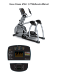
S7x-01 Stepper
S ER V I C E M A N U A l
Table of contents
CHAPTER 1: Serial number location . .................................................................. 1
CHAPTER 2: Important Safety instructions
2.1
2.2
Before Getting Started ............................................................................................... 3
Read and Save These Instructions . .......................................................................... 4
CHAPTER 3: Preventative Maintenance
3.1
3.2
3.3
Recommended Cleaning Tips . .................................................................................. 5
Check for Damaged Parts ......................................................................................... 5
Care and Maintenance Instructions ........................................................................... 6
CHAPTER 4: CONSOLE OVERLAY AND WORKOUT DESCRIPTION
4.1
4.2
4.3
4.4
4.5
4.6
Console Description ...................................................................................................
Workout Setup Steps - Manual...................................................................................
Workout Setup Steps - Level Based...........................................................................
Workout Setup Steps - Fitness Test............................................................................
Workout Setup Steps - Target Heart Rate..................................................................
Workout Setup Steps - Constant Watts......................................................................
7
8
8
9
10
10
CHAPTER 5: Manager MODE
5.1
5.2
5.3
5.4
5.5
5.6
Manager
Manager
Manager
Manager
Manager
Manager
Mode
Mode
Mode
Mode
Mode
Mode
...........................................................................................................
- About Tab.........................................................................................
- Time Tab..........................................................................................
- Defaults Tab.....................................................................................
- Language Tab..................................................................................
- TV Tab.............................................................................................
CHAPTER 6: ENGINEERING MODE
6.1
6.2
6.3
6.4
6.5
6.6
Engineering
Engineering
Engineering
Engineering
Engineering
Engineering
CHAPTER 7: SERVICE MODE
7.1
7.2
7.3
7.4
7.5
Service
Service
Service
Service
Service
Mode
Mode
Mode
Mode
Mode
Mode
Mode
Mode
Mode
Mode
Mode
Overview.......................................................................................
- Errors Tab...................................................................................
- Statistics Tab..............................................................................
- Self Power Tab...........................................................................
- Clubs Tab....................................................................................
- Club ID Tab.................................................................................
Overview..............................................................................................
- Setup Tab...........................................................................................
- Test Tab.............................................................................................
- Date & Time Tab................................................................................
- Log Tab..............................................................................................
11
12
13
14
15
16
17
18
19
20
21
22
23
24
25
26
27
i
Table of contents
CHAPTER 8: Troubleshooting
8.1
8.2
8.3
8.4
8.5
8.6
8.7
8.7
8.8
Electrical Diagram ......................................................................................................
Error Codes on the Console ......................................................................................
LCB LED Indicators....................................................................................................
Troubleshooting - Display Issues................................................................................
Troubleshooting - Error 0x04A0..................................................................................
Troubleshooting - Keypad Issues................................................................................
Troubleshooting - Entertainment Keypad Issues........................................................
Troubleshooting - Heart Rate Issues..........................................................................
Troubleshooting - TV Issues.......................................................................................
28
29
30
31
32
33
34
35
36
Chapter 9: PART REPLACEMENT GUIDE
9.1
9.2
9.3
9.4
9.5
9.6
9.7
9.8
9.9
9.10
9.11
9.12
9.13
9.14
9.15
9.16
9.17
9.18
9.19
9.20
9.21
9.22
Console Replacement................................................................................................. 37
Heart Rate Handlebar Replacement . ........................................................................ 38
Heart Rate Grip Replacement ................................................................................... 39
Cup Holder Replacement............................................................................................ 40
Console Keypad / Overlay Replacement.................................................................... 41
Console Mast Removal............................................................................................... 43
Upper Stationary Handlebar Replacement................................................................. 44
Lower Stationary Handlebar Replacement................................................................. 45
Rear Stabilizer Cover Replacement............................................................................ 46
Rear Stabilizer Replacement ..................................................................................... 47
Shrouds Replacement................................................................................................. 48
Lower Control Board Replacement............................................................................. 49
ECB (Electromagnetic Brake) Belt Replacement....................................................... 50
ECB (Electromagnetic Brake) Replacement............................................................... 52
Center Axle Set Replacement..................................................................................... 53
Drive Belt Replacement ............................................................................................. 55
Drive Axle Set Replacement....................................................................................... 57
Pedal Replacement..................................................................................................... 59
Pedal Belt Replacement.................................................................................................. 60
Pedal Arm Replacement.................................................................................................. 61
Battery Replacement....................................................................................................... 62
Testing the Stepper.......................................................................................................... 63
CHAPTER 10: stepper specifications and assembly guide
ii
iv
10.1
10.2
10.3
10.4
10.5
S7x Stepper Specifications.........................................................................................
Fasteners and Assembly Tools...................................................................................
Assembly Instructions ................................................................................................
Leveling the Stepper...................................................................................................
TV Programming Instructions.....................................................................................
64
65
66
70
71
CHAPTER 11: SOFTWARE UPGRADE GUIDE
11.1 Software Upgrade Instructions..................................................................................... 73
Chapter 1: serial number location
1.1 Serial Number Location
A serial number plate is located below the bottom of the console mast beneath a rubber boot. There is also a serial number tag on the middle
of the main frame pointed towards the floor.
1
Chapter 1: serial number location
1.1 SERIAL NUMBER LOCATION - CONTINUED
universal console serial number location
2
Chapter 2: Important Safety Instructions
2.1 Before Getting Started
The Matrix S7x-01 Stepper is intended for commercial use. To
ensure your safety and protect the equipment, read all instructions
before operating the stepper.
CHOOSING A SITE
The site should be well lit and well ventilated. Locate the Matrix
S7x-01 Stepper on a structurally solid and flat surface. The Stepper
should have a clearance of 20" on the back side from the wall or
other equipment. This zone is to allow easy access to the Stepper
and gives the user an easy exit path from the machine. If the site
has a heavy plush carpet, to protect the carpeting and machinery,
you should place a rigid plastic base under the unit.
Please do not place the Matrix S7x-01 Stepper in an area of high
humidity, such as the vicinity of a steam room, indoor pool, or sauna.
Exposure to intensive water vapor or chlorine could adversely affect
the electronics, as well as other parts of the machine.
ELECTRICAL REQUIREMENTS
The Matrix S7x-01 Stepper can be operated without power;
however, the machine must boot the software with each new user.
This can mean a delay of up to 35 seconds while the machine's
operating system prepares for a workout. It's similar to turning your
cell phone on for the first time of the day. These units can also be
AC powered. This will power the console at all times and requires
no minimum RPM for operation. A powered product lowers the
starting resistance and is easier to use for beginners. These units
can be daisy chained together, up to 4 units per dedicated 15 amp
circuit, using a Matrix daisy chain cord adapter (sold separately).
If the battery must be recharged, use the optional power adapter
charging unit. The charger should be connected to the Stepper
for a minimum of eight hours to ensure a thorough charge. After a
completion of charge, the battery light turns from red into green (see
illustration). If LOW BATTERY still appears on the display with a
fully charged battery, the battery could be extinct. Please check with
an authorized service technician for replacing the battery.
CAUTION
The battery stored inside the unit contains materials hazardous to the
environment. Proper disposal of the battery is required by law.
GROUNDING INSTRUCTIONS:
The Matrix Stepper must be grounded. If it should malfunction or
break down, grounding provides a path of least resistance for electric
current to reduce the risk of electric shock. The Stepper is equipped
with a cord having an equipment grounding conductor and a
grounding plug. The plug must be plugged into an appropriate outlet
that is properly installed and grounded in accordance with all local
codes and ordinances. If the user does not follow these grounding
instructions, the user could void the Matrix limited warranty.
DANGER: Improper connection of the equipment grounding
conductor can result in the risk of electric shock. Check with a
qualified electrician if the user is in doubt as to whether the product
is properly grounded. Do not modify the plug provided with the
product if it will not fit the outlet, have a proper outlet installed by an
electrician.
For your safety and the performance of your Matrix product, the
ground on your circuits must be non-looped. Please refer to NEC
article 210-21 and 210-23. Any alterations to the standard Matrix
power cords will void all warranties.
The S7x-01 Stepper saves its battery charge by moving into a
shutdown mode whenever STEP FASTER appears on the display.
If the user does not maintain a step rate above 35 steps per
minute, then a 30 second shutdown process begins. When the
battery voltage is low, LOW BATTERY appears on the display if the
unit is moving into the shutdown mode. The following situation is
the time to recharge the battery:
* If no one has used the unit for an extended period of time, the
battery may need recharging.
* The unit continues to function with a low battery, however, user
and program information is lost once the user stops.
3
Chapter 2: Important Safety Instructions
2.2 Read and Save these instructions
To ensure your safety and protect the equipment, read all
instructions before operating the Matrix S7x-01 Stepper.
To ensure proper use of the Stepper, make sure that all users
read this manual. Remind the users that before undertaking any
fitness program, they should obtain complete physical examinations
from their physicians. If, at any time while exercising, the user
experiences dizziness, pain, or shortness of breath, nausea or feels
faint, he or she must stop immediately.
* This stepper is only to be used for its intended purpose described
in this manual. Do not use attachments that have not been recommended by Matrix.
* Never drop or insert objects into any opening. Keep hands away
from moving parts. If the item cannot be reached, contact a Matrix
authorized dealer for assistance.
* Never operate the unit if it is damaged, not working properly, when
it has been dropped, or has been dropped in water.
* Keep hands and feet clear at all times from moving parts to avoid
injury.
* Do not use this product outdoors, near swimming pools or in areas
of high humidity.
* Do not operate where aerosol (spray) products are being used or
when oxygen is being administered.
* Do not use this product in bare feet. Do not wear shoes with heels,
leather soles, cleats, or spikes while exercising.
* Do not remove the side covers. Service should only be done by an
authorized service technician.
* Close supervision is necessary when used near children, invalids,
or disabled people.
* When the stepper is in use, young children and pets should be kept
at least 3 meters / 10 feet away.
* Assemble and operate the stepper on a solid, level surface.
* Never face backward while using the stepper.
* Use the stationary handlebars when mounting or dismounting the
stepper.
* Do not wear clothing that might catch on any moving parts of this
stepper.
4
CAUTION! If you experience chest pains, nausea, dizziness,
or shortness of breath, stop exercising immediately and consult your physician before continuing.
CAUTION! Any changes or modifications to this equipment
could void the product warranty.
Chapter 3: preventative maintenance
3.1 recommended cleaning tips
Preventative maintenance and daily cleaning will prolong the life and
look of your Matrix S7x-01 Stepper.
Please read and follow these tips.
*Position the equipment away from direct sunlight. The intense UV
light can cause discoloration on plastics.
*Locate your equipment in an area with cool temperatures and low
humidity.
* Clean with a soft 100% cotton cloth.
*Clean with soap and water or other non-ammonia based all purpose cleaners.
*Wipe the pedals, console, heart rate grips, and the handlebar
clean after each use.
3.2 Check for damaged parts
DO NOT use any equipment that is damaged or has worn or
broken parts. Use only replacement parts supplied by Matrix
Fitness Systems.
MAINTAIN LABELS AND NAMEPLATES. Do not remove labels
for any reason. They contain important information. If unreadable
or missing, contact Matrix Fitness Systems for a replacement at
866-693-4863 or www.matrixfitness.com.
MAINTAIN ALL EQUIPMENT. Preventative maintenance is the
key to smoothly operating equipment. Equipment needs to be
inspected at regular intervals. Defective components must be
kept out of use until they are repaired. Ensure that any person(s)
making adjustments or performing maintenance or repair of any
kind is qualified to do so. Matrix Fitness Systems will provide
service and maintenance training at our corporate facility upon
request or in the field if proper arrangements are made.
*Do not pour liquids directly onto your equipment. This can cause
damage to the equipment and in some cases electrocution.
** Adjust leveling feet when equipment wobbles or rocks.
* Maintain a clean area around the equipment, free from dust and
dirt.
5
Chapter 3: preventative maintenance
3.3 Care and maintenance instructions
In order to maximize life span, and minimize down time, all Matrix
equipment requires regular cleaning, and maintenance items
performed on a scheduled basis. This section contains detailed
instructions on how to perform these items and the frequency of
which they should be done. Some basic tools and supplies will be
necessary to perform these tasks which include (but may not be
limited to):
* Metric Allen wrenches
* #2 Phillips head screwdriver
* Adjustable wrench
* Torque wrench (capability to read foot lbs and inch lbs)
* Lint free cleaning cloths
* Teflon based spray lubricant such as "Super Lube" or other Matrix
approved products.
* Mild water soluable detergent such as "Simple Green" or other
Matrix approved products
* Vacuum cleaner with an extendable hose and crevasse tool
attachment.
You may periodically see addendums to this document, as the
Matrix Technical Support Team identifies items that require specific
attention, the latest version will always be available on the Matrix
web site at www.matrixfitness.com.
DAILY MAINTENANCE ITEMS
1) Look and listen for loose fasteners, unusual noises, and any
other indications that the equipment may be in need of service.
2) Clean the stepper before and after each use, including:
a. Use a damp, soft cloth with water or mild liquid detergent
to clean all exposed surfaces. DO NOT use ammonia, chlorine, or
any acid based cleaners.
b. Keep the console display free of fingerprints and salt build
up caused by sweat.
WEEKLY MAINTENANCE ITEMS
1) Frequently vacuum the floor beneath the unit to prevent the
accumulation of dust and dirt which can affect the smooth operation
of the unit.
2) Check the pedals and belts for damage.
3) Check the unit for a low battery charge, recharge if needed.
MONTHLY MAINTENANCE ITEMS
1) Inspect the console, pedals, handlebars, and shrouds for
damage.
2) Adjust the leveling feet if equipment rocks or wobbles.
QuARTERLY MAINTENANCE ITEMS
1) Remove the front shrouds and check the belts for damage,
alignment, and proper tension.
6
Chapter 4: console overlay and workout description
4.1 Console Description
MULTI-PURPOSE KEYS: Keys have different functions depending on
each screen.
S7x ENTERTAINMENT ZONE
GO: One touch Start.
iPOD®: Will take the user directly to the iPod screen to allow for iPod
control and playlist selecton.
ENTER: To confirm each program setting.
UP / DOWN LEVEL: Easy information and level selection.
UP / DOWN TIME: Easy information and time adjustment.
STOP: Ends workout and shows workout summary data.
NUMBER KEYPAD: Workout data input for workout setup. Level
adjustment during workout.
COOL DOWN: Puts the stepper into Cool Down mode.
VOLUME UP / DOWN: Adjusts the volume output through the headphone
jack of the integrated console TV or iPod output.
NUMBER KEYPAD: Allows for easy TV channel selection.
CHANNEL UP / DOWN: Allows for channel selection.
DISPLAY MODE: Allows user to cycle through console display options,
iPod, TV, or profile display.
LAST CHANNEL: Allows the user to cycle between the current channel
and the previous channel viewed.
FAN: Allows for fan speed selection (fan has 3 operating speeds).
TOGGLE DISPLAY: Allows the user to select what information is
displayed on the console.
7
Chapter 4: console overlay and workout description
4.2 workout setup steps - manual
4.3 workout setup steps - level based
GO - Press to immediately begin a workout. Workout, resistance
RANDOM - A level based workout that randomly adjusts the
1) Start stepping and press the GO key to begin your workout. 2)
The display will read 3, 2, 1, and then the program will begin.
1)
2)
3)
4)
5)
level, and time will automatically go to default settings. Pressing
GO will not prompt user for age, weight, or level settings.
resistance of the machine.
Start stepping and press the key next to RANDOM.
Select the key next to LEVEL and follow the prompts to set.
Select the key next to TIME and follow the prompts to set.
Select the key next to WEIGHT and follow the prompts to set.
The display will read 3, 2, 1, and then the program will begin.
MANUAL - Manual allows the user to input more information
while defining their own workout. Calorie expenditure will be more
accurate when inputting information in Manual than by pressing GO.
1)
2)
3)
4)
5)
Start stepping and press the key next to MANUAL.
Select the key next to LEVEL and follow the prompts to set.
Select the key next to TIME and follow the prompts to set.
Select the key next to WEIGHT and follow the prompts to set.
The display will read 3, 2, 1, and then the program will begin.
ROLLING HILLS - The Rolling Hills program is a level based
program that automatically adjusts the resistance level to simulate
real terrain.
1)
2)
3)
4)
5)
Start stepping and press the key next to ROLLING HILLS.
Select the key next to LEVEL and follow the prompts to set.
Select the key next to TIME and follow the prompts to set.
Select the key next to WEIGHT and follow the prompts to set.
The display will read 3, 2, 1, and then the program will begin.
INTERVALS - The Intervals program is a level based program
that automatically adjusts the resistance of the machine from low to
high intensity settings at regular intervals.
1)
2)
3)
4)
5)
Start stepping and press the key next to INTERVALS.
Select the key next to LEVEL and follow the prompts to set.
Select the key next to TIME and follow the prompts to set.
Select the key next to WEIGHT and follow the prompts to set.
The display will read 3, 2, 1, and then the program will begin.
FAT BURN - Fat burn is a level based program that is designed
to help users burn fat through various resistance level changes.
1)
2)
3)
4)
5)
8
Start stepping and press the key next to FAT BURN.
Select the key next to LEVEL and follow the prompts to set.
Select the key next to TIME and follow the prompts to set.
Select the key next to WEIGHT and follow the prompts to set.
The display will read 3, 2, 1, and then the program will begin.
Chapter 2: Important Safety Instructions
4.4 WORKOUT SETUP STEPS - Fitness test
FITNESS TEST -The Fitness Test program is to monitor the
development of your cardiovascular system and measure your
fitness level based on your average heart rate during specific test
stages. When the 5 minute test is completed, the display provides
a fitness score.
1) Start stepping and press the key next to FITNESS TEST.
2) Select the key next to AGE and follow the prompts to set.
3) Select the key next to GENDER and follow the prompts to set.
4) Select the key next to WEIGHT and follow the prompts to set.
5) The display will read 3, 2, 1, and then the program will begin.
6) Once the workout is complete, the display will read the results
of the Fitness Test.
MEN'S OUTPUT TABLE FOR FITNESS TEST
age
excellent
GOOD
above
average
average
below
average
poor
VERY
POOR
18-25
<79
79-89
90-99
100-105
106-116
117-128
>128
26-35
<81
81-89
90-99
100-107
108-117
118-128
>128
36-45
<83
83-96
97-103
104-112
113-119
120-130
>130
46-55
<87
87-97
98-105
106-116
117-122
123-132
>132
56-65
<86
86-97
98-103
104-112
113-120
121-129
>129
65+
<88
88-96
97-103
104-113
114-120
121-130
>130
WOMEN'S OUTPUT TABLE FOR FITNESS TEST
age
excellent
GOOD
above
average
average
below
average
poor
VERY
GOOD
18-25
<88
85-98
99-108
109-117
118-126
127-140
>140
26-35
<88
88-99
100-111
112-119
120-126
127-138
>138
36-45
<90
90-102
103-110
111-118
119-128
129-140
>140
46-55
<94
94-104
105-115
116-120
121-129
130-135
>135
56-65
<95
95-104
105-112
113-118
119-128
129-139
>139
65+
<90
90-102
103-115
116-122
123-128
129-134
>134
9
Chapter 4: console overlay and workout description
4.5 Workout Setup steps - target heart rate
TARGET HEART RATE - The Matrix stepper comes with
standard digital contact heart rate sensors and are POLAR telemetry
compatible. The heart rate conrol workout mode allows the user
to program their desired heart rate zone, and the stepper will
automatically adjust the level based upon the user's heart rate. The
heart rate zone is calculated using the following equation: (220Age)8%=target heart rate zone. The user must wear a POLAR
telemetric strap or continually hold onto the contact heart rate grips
for this workout.
Locate the metal sensors on the handlebars of the stepper. Notice
that there are two separate pieces of metal on each grip. You must
be making contact with both pieces of each grip to get an accurate
heart rate reading. You can grab these sensors in any program to
view your current heart rate.
1) Start stepping and press the key next to TARGET HEART RATE.
2) Select the key next to AGE and follow the prompts to set.
3) Select the key next to PERCENTAGE OF HR and follow the
prompts to set.
4) Select the key next to TIME and follow the prompts to set.
5) Select the key next to WEIGHT and follow the prompts to set.
6) The display will read 3, 2, 1, and then the program will begin.
10
4.6 workout setup steps - constant watts
CONSTANT WATTS - Constant Watts is a unique program
that allows you to vary your cadence or RPM and the stepper's
resistance level will adjust accordingly to your selected goal. The
quicker you step, the less resistance for the goal selected.
1)
2)
3)
4)
5)
Start stepping and press the CONSTANT WATTS key.
Select the key next to WATT and follow the prompts to set.
Select the key next to TIME and follow the prompts to set.
Select the key next to WEIGHT and follow the prompts to set.
The display will read 3, 2, 1, and then the program will begin.
Chapter 5: manager mode
5.1 Manager Mode overview
The Manager's Custom Mode allows the club owner to customize the stepper for the club.
1) To enter Manager Mode, press ENTER, 1, 0, 0, 1, ENTER on the upper display. Manager Mode will appear on the display (Figure A).
2) Select the key next to the setting that needs to be changed, and follow the prompts to change.
3) Press the ENTER key once the desired setting is correct to save.
4) Press HOME or press and hold the STOP key for 3-5 seconds to return to normal operation.
figure a
11
Chapter 5: manager mode
5.2 manager mode - about tab
manager mode
About
12
Function & defaults
descriptions
modified
Versions
Software version.
Cannot be modified.
Key Sound
Default: On
Controls whether there is a key sound when
a key is pressed and whether it is a beep or
through the speakers.
On / Off
Out of Order
Default: Off
This option allows the club to put the console
into an "out of order" status.
On / Off
Chapter 5: manager mode
5.3 manager mode - time tab
Manager mode
Time
function & defaults
descriptions
modified
Maximum Time
Default: 60 Minutes
This option allows the club to set the
maximum workout duration limits during
peak and non peak hours.
Maximum: 99 Minutes
Minimum: 5 Minutes
Pause Time
Default: 5 Minutes
This option controls the default pause time.
Maximum: 10 Minutes
Minimum: 1 Minute
13
Chapter 5: manager mode
5.4 manager mode - defaults tab
manager mode
Defaults
14
function & defaults
description
modified
Level
Default: 1
This option controls the dafault
program level.
Maximum: 1
Minimum: 20
Age
Default: 30
This option controls the default user's
age used in the target HR calculations.
Maximum: 100
Minimum: 10
Weight
Default: 150 lbs / 68 kg
This option controls the default weight
used in the calorie calculations.
Displayed in pounds or kilograms.
Maximum: 400 lbs / 180 kg
Minimum: 80 lbs / 36 kg
Gender
Default: Male
Setting the user as Male or Female.
Male or Female
Time
This option controls the default
program time.
Maximum: Max Time Setting
Minimum: 5 Minutes.
Chapter 5: manager mode
5.5 manager mode - language tab
manager mode
Language
language
English
function & defaults
Select default language.
flag
unit
Mile
language
Spanish
modified
flag
unit
km
language
Chinese
km
Mile
German
descriptions
This option allows the user to select a flag for a
specific language.
KM
Dutch
km
KM
Italian
km
KM
Japanese
km
N/A
flag
unit
km
km
Portuguese
km
km
French
km
15
Chapter 5: manager mode
5.6 manager mode - tv tab
manager mode
TV
16
function & defaults
descriptions
modified
Channel
Default: 1
This option controls the default TV channel
on start up.
Channels 1-999
Volume
Default: 1
This option controls the default TV volume
on start up.
Maximum: 17
Minimum: 1
Channel Scan
This option scans the local TV system for
channels.
N/A
External TV
Default: Off
This option controls the external TV power.
On / Off
Chapter 6: engineering mode
6.1 engineering mode overview
The Engineering Mode allows the club owner to keep track of the technical settings and error history for the stepper.
1) To enter Engineering Mode, press ENTER, 2, 0, 0, 1, ENTER on the upper display. Engineering Mode will appear on the display (Figure A).
2) Select the key next to the setting that needs to be changed, and follow the prompts to change.
3) Press the ENTER key once the desired setting is correct to save.
4) Press HOME or press and hold the STOP key for 3-5 seconds to return to normal operation.
figure a
17
Chapter 6: engineering mode
6.2 engineering mode - errors tab
engineering mode
Errors
18
function & defaults
descriptions
This option displays the error code
history.
modified
N/A
Chapter 6: engineering mode
6.3 engineering mode - statistics tab
engineering mode
Statistics
function & defaults
descriptions
This option displays the workout
information for the unit.
modified
N/A
19
Chapter 6: engineering mode
6.4 engineering mode - self power tab
engineering mode
Self Power
20
function & defaults
descriptions
modified
Threshold
Default: 25 RPM
This option controls the minimum RPM limits for
operation.
25 - 60 RPM
Disconnect
This option controls the minimum RPM limit to
operate other functions when no power is present.
20 - 60 RPM
Keep Time
This option controls how long the console keeps
information after the minimum RPM threshold is not
met.
Home: 60 Seconds
Run: 30 Seconds
Summary: 30 Seconds
Chapter 6: engineering mode
6.5 engineering mode - clubs tab
engineering mode
function & defaults
Clubs
Default: MATRIX
descriptions
This option allows the club to select a screen
header from a list.
modified
N/A
21
Chapter 6: engineering mode
6.6 ENGINEERING MODE - club id tab
engineering mode
function & defaults
Club ID
22
descriptions
This option records the Club ID of
the fitness facility.
modified
N/A
Chapter 7: service mode
7.1 SERVICE MODE OVERVIEW
The Service Mode allows an authorized service provider to test and store information on the stepper.
1) To enter Service Mode, press ENTER, 3, 0, 0, 1, ENTER on the upper display. Service Mode will appear on the display (Figure A).
2) Select the key next to the setting that needs to be changed, and follow the prompts to change.
3) Press the ENTER key once the desired setting is correct to save.
4) Press HOME or press and hold the STOP key for 3-5 seconds to return to normal operation.
figure a
23
Chapter 7: service mode
7.2 service mode - setup tab
service mode
Setup
24
function & defaults
descriptionS
Machine Type
Default: Stepper
This option selects the current model.
Serial Number
This option displays the serial number of the console and frame.
Accumulated Distance
This option displays the accumulated workout distance since production.
Accumulated Time
This option displays the accumulated workout time since production.
Show Boot
Factory Setting Only.
Chapter 7: service mode
7.3 service mode - test tab
service mode
Test
function & defaults
Keypad
descriptions
This option is for a keypad test.
25
Chapter 7: service mode
7.4 service mode - date & time tab
service mode
Time
26
function & defaults
Date & Time
descriptions
This option sets the current date and time on
the machine.
Chapter 7: service mode
7.5 service mode - log tab
service mode
Log
function & defaults
descriptions
Delete
This option deletes key components replacement
history.
Create
This option creates key components replacement
history.
27
Chapter 8: troubleshooting
8.1 electrical diagrams
28
Chapter 8: troubleshooting
8.2 error codes on the console
code
class
description
solution
0x0441
b
When the UCB implements
a command, the LCB is not
receiving this command.
Check the machine type in
Engineering Mode. Check the
console cable connections at the
UCB and LCB.
0x02AB
c
Machine type error.
Set the correct machine type in
Engineering Mode.
0x02B3
c
Resistance type error.
Set the correct machine type in
Engineering Mode.
0x04A0
c
Digital Communication Failure.
LCB has no return message for
the UCB for 3 seconds.
Check the console cable
connections at the UCB and
LCB. Replace the UCB or LCB
as needed.
0x0201
a
Low voltage on the battery
(voltage under 11.2V).
Charge the battery by running or
by plugging in the AC adapter.
0x0247
b
LCB failed (memory write error /
feedback ADC error).
Replace the LCB.
0x0248
b
Battery failure or disconnection
(Voltage under 8V or over 15V).
Check the wire connections at
the battery. Replace the battery.
CLASS C errors will display on the console.
Class A or B errors will only display in Service Mode 5.
29
Chapter 8: troubleshooting
8.3 lcb led indicators
led indicator
description
LED 1
RPM (AC Plug In).
LED 2
+5V
LED 3
+15V
LED 4
Bus Voltage
LED 5
RPM (Generator).
LED 6
Status 1 (Program operation).
LED 7
Status 2 (Resistance value in middle 1/2 VCC).
LED 8
Status 3 (Digital Communication).
LED 9
+12V (Console Power).
WITHOUT AC PLUG - Normal
LED 2 - LED 9 - On.
LED 1 - Off (No AC plug detected).
LED 5 - On (Generator power detected),
WITH AC PLUG - NORMAL
LED 2 - LED 9 - On.
LED 1 - On (AC plug detected).
LED 5 - Off (No Generator power detected).
led 1
led 5
30
Chapter 8: troubleshooting
8.4 Troubleshooting - display issues
no display on the console or the display is dim when running
led 9
led 1
led 8
led 5
symptom: The console will not power up or the display is dim.
check point
possible issue
solution
LEDs 2, 3, 4, 6, and 7 should be ON.
If they are OFF, the LCB is damaged.
Replace the LCB.
If LED 1 is OFF.
No AC power cord plugged in.
Normal for an unpowered unit.
If LED 5 is OFF.
Generator has no RPM output.
Normal for a powered unit. If unpowered and
issue is still present, replace the generator.
If LED 8 is OFF.
Bad communication between UCB and LCB.
Reconnect the console cable at the LCB and
UCB and check for kinks.
If LED 9 is OFF.
LCB is not providing 12V power to the UCB.
Replace the LCB.
solution if LEDs are normal:
1) If the LEDs are lit normally, replace the UCB and console cable.
2) if the issue is still present after the UCB and console cable are replaced, replace the LCB.
31
Chapter 8: troubleshooting
8.5 Troubleshooting - error 0x04A0
error 0x04A0 (Digital communication failure)
led 1
led 8
symptom: Error code 0x04A0 is displayed on the console.
check point
possible issue
solution
LEDs 2, 3, 4, 6, and 7 should be ON.
If they are OFF, the LCB is damaged.
Replace the LCB.
If LED1 is OFF.
No AC power cord plugged in.
Normal for an unpowered unit.
If LED 8 is OFF.
Bad communication between UCB and LCB.
Reconnect the console cable at the LCB and
UCB and check for kinks.
Solution if leds are normal:
1) If the LEDs are lit normally, replace the UCB and console cable.
2) if the issue is still present after the UCB and console cable are replaced, replace the LCB.
32
Chapter 8: troubleshooting
8.6 troubleshooting - keypad issues
all or some of the function keys do not respond
possible causes:
1) The keypad connection ribbon cable has not been plugged in correctly.
2) The keypad is damaged.
3) The UCB is damaged.
SOLUTION:
1) Perform a keypad test in Service Mode:
a. Press ENTER, 3, 0, 0, 1, ENTER on the upper display and Service Mode will appear on the display.
b. Press the key next to TEST on the display.
c. Press the key next to KEYPAD on the display.
c. Test the affected keypad. If the keypad works in the keypad test it may not be a functioning key in the program used for testing it.
2) Check the connections of the keypad at the UCB.
a. Remove the console from the console mast.
b. Remove the 6 screws holding the back of the console to the front (Figure A).
c. Inspect the keypad ribbon cable connection at the UCB (Figure B).
d. Even if the keypad ribbon cable appears to be connected correctly, unplug and reseat the cable, then retest.
3) Replace the affected keypad.
4) Replace the UCB.
figure a
figure b
33
Chapter 8: troubleshooting
8.7 troubleshooting - Entertainment keypad issues
PROBLEM:
The entertainment keypad is not recognizing the correct keys.
SOLUTION:
1) Perform a keypad test. To do so:
a. Press ENTER, 3, 0, 0, 1, ENTER on the upper keypad to enter Service Mode.
b. Press the key next to TEST on the display.
c. Press the key next to KEYPAD on the display.
d. The entertainment keypad can now be tested. Press various keys to see if the console is recognizing the correct keys (Figure A). If
not, proceed to Step 2.
2) There are 2 different entertainment keypads available for the S7x Stepper. To change which key sequence is utilized:
a. Press ENTER, 3, 0, 6, 0, ENTER on the upper keypad.
b. The console should chime twice.
c. Re-test the entertainment keypad, it should now recognize the correct keys.
34
Chapter 8: troubleshooting
8.8 TROUBLESHOOTING - HEART RATE ISSUES
heart rate function does not work or is reading incorrectly
possible causes:
1)
2)
3)
4)
5)
6)
The
The
The
The
The
The
chest strap being used is not making good contact with the user's chest.
chest strap is at a low battery status.
chest strap is damaged.
HR grips are damaged.
HR board is damaged.
UCB is damaged.
SOLUTION:
1) Recenter the chest strap below the user's pectoral muscle (Figure A) and check again.
2) Replace the battery in the chest strap.
3) Replace the chest strap.
4) If there is no HR present, replace the HR grips.
5) If there is a HR present but it is much higher than normal, replace the HR board.
6) If replacing the HR grips and board does not resolve the issues, replace the console.
FIgure A
35
Chapter 8: troubleshooting
8.9 troubleshooting - tv issues
1) This section will help with diagnosing problems with the integrated screen TV for the Matrix S7x-01 Stepper.
2) The TV should have power whenever the unit is powered up. If the TV will not power up when the power button is pressed:
a) Press ENTER, 3, 0, 0, 1, ENTER on the upper number keypad. Press the key next to TEST. Check to make sure that it says
INCLUDE POWER next to the TV Keypad option. If it is excluded, change to include power and retry the TV power.
b) If the TV Keypad option is correct and the TV still will not power up, replace the console.
3) For a fuzzy or unclear picture, see the TV programming instructions in Section 10.5. If the TV is still fuzzy or unclear after programming:
a) Check the coax connection at the entertainment port (Figure A).
b) Remove the 4 screws holding the console to the console mast and check the coax connection at the console (Figure B).
c) Move the coax cable to directly plug into the back of the console bypassing the entertainment port. If this resolves the issue, replace
the internal coax cable.
d) If plugging the coax cable into the back of the console does not resolve the issue, check the coax cable with a known working
television. If the coax cable is good, replace the console.
figure a
36
figure b
Chapter 9: part replacement guide
9.1 CONSOLE REPLACEMENT
1) Remove the 4 screws holding the console to the frame (Figure A).
2) Disconnect the console cable and HR connections from the defective console and remove the console (Figure B).
3) Reinstall the wire connections to the new console.
4) Carefully push the wires into the console mast until they are clear of the console / mast connection and attach the console to the mast using
the 4 screws removed in Step 1.
5) Test the stepper for function as outlined in Section 9.22.
Figure A
Figure B
37
Chapter 9: part replacement guide
9.2 HEART RATE HANDLEBAR REPLACEMENT
1)
2)
3)
4)
5)
Remove the console as outlined in Section 9.1.
Remove the 3 screws holding on the heart rate handlebar to the console mast being careful to support the handlebar (Figure A).
Carefully pull the wires from the console mast until the connectors are free and remove the defective handlebar (Figure B).
Reverse Steps 1-3 to install a new handlebar.
Test the stepper for function as outlined in Section 9.22.
Figure A
Figure B
38
Chapter 9: part replacement guide
9.3 HEART RATE GRIPS REPLACEMENT
1) Using a flat screwdriver, pry the silver metal heart rate plate on the back side of the HR grip away from the plastic of the HR grip (Figure A).
2) Remove the 3 screws holding the HR grip together (Figure B). NOTE: You may need to remove the console to give access to the HR grip
screws.
3) Disconnect the HR grip wire and remove the metal plate (Figure C).
4) Disconnect the level button and remove the two halves of the HR grip (Figure D).
5) Reverse Steps 1-4 to install new HR grips.
6) Test the stepper for function as outlined in Section 9.22.
Figure A
Figure C
Figure B
Figure D
39
Chapter 9: part replacement guide
9.4 CUP HOLDER REPLACEMENT
1) Remove the 2 screws holding the cup holder to the console mast (Figure A).
2) Remove the cup holder (Figure B).
3) Reverse Steps 1-2 to install a new cup holder.
Figure A
Figure B
40
Chapter 9: part replacement guide
9.5 CONSOLE KEYPAD / OVERLAY REPLACEMENT
1) Remove the console as outlined in Section 9.1.
2) Remove the back cover of the console (Figure A).
4) Unplug and remove the faulty overlay (Figure B).
5) Clean the console area with alcohol to remove any left over adhesive (Figure C).
6) Remove the protective film over the display window of the overlay (Figure D).
7) Peel part of the protective film from the back of the overlay (Figure E).
8) Push the overlay ribbon cable through the hole in the console and plug it in (Figure F).
9) Match the overlay to the cutout on the console (Figure G).
10) Press down on the corners of the overlay to keep it in place, then remove the protective film (Figure H & I).
11) Once the overlay is in the correct position, press down on the overlay with a cloth to adhere it to the console plastic (Figure J).
12) Use the same procedure to replace any additional faulty overlays. NOTE: Overlays can not be reused.
13) Test the stepper for function as outlined in Section 9.22.
Figure A
Figure C
Figure B
Figure D
41
Chapter 9: part replacement guide
9.5 CONSOLE KEYPAD / OVERLAY REPLACEMENT - CONTINUED
Figure E
Figure F
Figure G
Figure H
figure i
42
figure j
Chapter 9: part replacement guide
9.6 console mast removal
1) Remove the console as outlined in Section 9.1.
2) Remove the HR handlebars as outlined in Section 9.2.
3) Remove the 2 screws holding the stationary handlebar junction to the console mast and pull the handlebars away from the console mast
(Figure A).
4) Lift up the rubber boot at the bottom of the console mast (Figure B), and remove the 4 screws holding the console mast to the frame (Figure C).
5) Pull the wires out the bottom of the console mast and remove the mast.
6) Reverse Steps 1-5 to install a new console mast. NOTE: When installing a new console mast, be sure to pull the console wires up through the
new mast prior to installing the 4 screws into the frame.
7) Test the stepper for function as outlined in Section 9.22.
Figure A
Figure B
figure c
43
Chapter 9: part replacement guide
9.7 UPPER STATIONARY HANDLEBAR REPLACEMENT
1) Remove the 2 screws holding the upper stationary handlebar junction to the console mast and lean it away from the console mast (Figure A).
2) Pull the defective upper stationary handlebar out of the upper stationary handlebar junction (Figure B).
3) Remove the 2 screws holding the bottom of the defective upper stationary handlebar to the lower stationary handlebar (Figure C).
4) This will allow you to remove the upper stationary handlebar (Figure D).
5) Reverse Steps 1-4 to install a new upper stationary handlebar. NOTE: Be sure to tighten the upper handlebar junction screws so that the
handlebars are even.
Figure A
figure c
44
Figure B
figure d
Chapter 9: part replacement guide
9.8 LOWER STATIONARY HANDLEBAR REPLACEMENT
1)
2)
3)
4)
Remove the upper stationary handlebar on the side with a defective lower stationary handlebar as outlined in Section 9.7.
Remove the 2 screws holding the lower stationary handlebar to the rear stabilizer (Figure A).
This will allow you to remove the lower stationary handlebar from the unit (Figure B).
Reverse Steps 1-3 to install a new lower stationary handlebar.
Figure A
Figure B
45
Chapter 9: part replacement guide
9.9 REAR STABILIZER COVER Replacement
1) Remove the 4 screws holding the rear stabilizer cover to the frame (Figure A).
2) Pull the rear stabilizer cover upward and off the unit (Figure B).
3) Reverse Steps 1-2 to install a new rear stabilizer cover.
Figure A
Figure B
46
Chapter 9: part replacement guide
9.10 Rear Stabilizer replacement
1) Remove the upper stationary handlebars as outlined in Section 9.7.
2) Remove the lower stationary handlebars as outlined in Section 9.8.
3) Remove the rear stabilizer cover as outlined in Section 9.9.
4) Remove the 4 screws holding the rear stabilizer to the frame and remove the stabilizer (Figure A).
5) Reverse Steps 1-4 to install a new rear stabilizer. NOTE: When installing a new stabilizer, the leveling feet may need to be transferred from
the old stabilizer to the new one (Figure B).
Figure A
Figure B
47
Chapter 9: part replacement guide
9.11 Shrouds removal
1) Remove the 10 screws holding the right side shroud to the frame (Figure A).
2) Remove the 10 screws holding the left side shroud to the frame (Figure B).
3) Figure C shows the stepper with both shrouds removed.
figure a
figure b
figure c
48
Chapter 9: part replacement guide
9.12 LOWER CONTROL BOARD REPLACEMENT
1)
2)
3)
4)
5)
Remove the right side shroud as outlined in Section 9.11.
Remove the wire connections to the lower board (Figure A).
Remove the 2 screws holding the lower board to the frame (Figure B), and remove the lower board.
Reverse Steps 1-3 to install a new lower board.
Test the stepper for function as outlined in Section 9.22.
figure a
figure b
49
Chapter 9: part replacement guide
9.13 ECB BELT REPLACEMENT
1) Remove both shrouds as outlined in Section 9.11.
2) Loosen the 6 screws holding the ECB to the frame (Figure A).
3) Loosen the eye bolt nut that applies tension to the ECB belt (Figure B) and slide the ECB towards the back of the unit to release the ECB
belt tension.
4) Walk the belt off of the ECB pulley (Figure C).
5) Loosen the 2 eye bolts holding the center axle to the frame (Figure D).
6) Lift up on the center axle and walk the belt off of the drive pulley (Figure E).
7) This will allow you to drop the center axle out of the frame and to remove the ECB belt (Figure F).
8) Reverse Steps 1-7 to install a new ECB belt. NOTE: Tighten the replacement ECB belt to 85 ft / lbs.
9) Test the stepper for function as outlined in Section 9.22.
fIGURE a
fIGURE b
50
Chapter 9: part replacement guide
9.13 ECb belt replacement - continued
fIGURE c
figure d
figure e
figure f
51
Chapter 9: part replacement guide
9.14 ECB (ELECTRONIC BRAKE) REPLACEMENT
1)
2)
3)
4)
5)
6)
7)
Remove the shrouds as outlined in Section 9.11.
Remove the 6 screws holding the ECB to the frame (Figure A).
Remove the nut from the tension eye bolt (Figure B).
Once the nut from the tension eye bolt has been removed, the ECB belt can be walked off the ECB pulley (Figure C).
Disconnect the ECB wire harness (Figure D), and remove the ECB.
Reverse Steps 1-5 to install a new ECB. NOTE: Be sure to retension the ECB belt to 85 ft / lbs. .
Test the stepper for function as outlined in Section 9.22.
fiGURE a
figure c
52
fIgure b
figure d
Chapter 9: part replacement guide
9.15 CENTER AXLE replacement
1)
2)
3)
4)
5)
6)
7)
8)
Remove the shrouds as outlined in Section 9.11.
Loosen the 6 screws holding the ECB to the frame (Figure A).
Loosen the nut from the tension eye bolt (Figure B).
Once the nut from the tension eye bolt has been removed, the ECB belt can be walked off the ECB pulley (Figure C).
Loosen the 2 eye bolts holding the center axle to the frame (Figure D).
Lift up on the center axle and walk the belt off of the drive pulley (Figure E).
This will allow you to drop the center axle out of the frame and to remove the ECB belt and center axle (Figures F).
Test the stepper for function as outlined in Section 9.22.
figure a
figure b
53
Chapter 9: part replacement guide
9.15 center axle replacement - continued
figure c
figure e
54
figure d
figure f
Chapter 9: part replacement guide
9.16 DRIVE BELT REPLACEMENT
1) Remove the shrouds as outlined in Section 9.11.
2) Loosen the 6 screws holding the ECB to the frame (Figure A).
3) Loosen the nut from the tension eye bolt (Figure B).
4) Once the nut from the tension eye bolt has been loosened, the ECB belt can be walked off the ECB pulley (Figure C).
5) Loosen the 2 eye bolts holding the center axle to the frame (Figure D).
6) Lift up on the center axle and walk the belt off of the drive pulley (Figure E).
7) This will allow you to drop the center axle out of the frame and to remove the drive belt from around it (Figures F).
8) Disconnect the 2 pedal belt springs from the around the drive axle set (Figure G).
9) Remove the 2 screws on each side holding the drive axle set to the frame (Figure H).
10) This will allow you to remove the drive axle set and drive belt.
11) Reverse Steps 1-10 to install a new drive belt. NOTE: Tighten the new drive belt to 145 ft / lbs.
12) Test the stepper for function as outlined in Section 9.22.
figure a
figure c
figure b
fIGURE D
55
Chapter 9: part replacement guide
9.16 drive belt Replacement - continued
Figure E
FIgure G
56
Figure F
figure h
Chapter 9: part replacement guide
9.17 Drive axle set replacement
1) Remove the shrouds as outlined in Section 9.11.
2) Loosen the 6 screws holding the ECB to the frame (Figure A).
3) Loosen the nut from the tension eye bolt (Figure B).
4) Once the nut from the tension eye bolt has been loosened, the ECB belt can be walked off the ECB pulley (Figure C).
5) Loosen the 2 eye bolts holding the center axle to the frame (Figure D).
6) Lift up on the center axle and walk the belt off of the drive pulley (Figure E).
7) This will allow you to drop the center axle out of the frame and to remove the drive belt from around it (Figure F).
8) Disconnect the 2 pedal belt springs from the around the drive axle set (Figure G).
9) Remove the 2 screws on each side holding the drive axle set to the frame (Figure H).
10) This will allow you to remove the drive axle set and drive belt.
11) Reverse Steps 1-10 to install a new drive axle set. NOTE: Tighten the new drive belt to 145 ft / lbs.
12) Test the stepper for function as outlined in Section 9.22.
Figure A
Figure B
figure c
figure d
57
Chapter 9: part replacement guide
9.17 drive axle set replacement - continued
58
figure e
figure f
figure g
figure h
Chapter 9: part replacement guide
9.18 pedal replacement
1)
2)
3)
4)
Remove the shrouds as outlined in Section 9.11.
Remove the 4 screws under the pedal frame going up into the plastic (Figures A & B).
This will allow you to remove the pedal (Figure C).
Reverse Steps 1-3 to install a new pedal.
figure a
figure b
figure c
59
Chapter 9: part replacement guide
9.19 Pedal Belt replacement
1) Remove the shrouds as outlined in Section 9.11.
2) Disconnect the pedal belt beneath the pedal frame by removing the 2 screws on the pedal retension bracket (Figure A).
3) This will allow you to remove the belt from the pedal frame (Figure B).
4) Disconnect the pedal belt spring from the drive axle set, and remove the pedal belt (Figure C).
5) Reverse Steps 1-4 to install a new pedal belt. NOTE: When reinstalling a new pedal belt, it is easier to attach the belt beneath the pedal
frame, then attach the pedal belt spring to the drive axle set.
6) Test the stepper for function as outlined in Section 9.22.
Figure B
Figure A
figure c
60
Chapter 9: part replacement guide
9.20 pedal arm replacement
1)
2)
3)
4)
5)
6)
7)
8)
Remove the shrouds as outlined in Section 9.11.
Remove the pedal as outlined in Section 9.18.
Disconnect the pedal belt beneath the pedal frame by removing the 2 screws on the pedal retension bracket (Figure A).
This will allow you to remove the belt from the pedal frame (Figure B).
Remove the snap ring holding the pedal arm to the frame (Figure C).
Remove the pedal arm (Figure D).
Reverse Steps 1-6 to install a new pedal arm.
Test the stepper for function as outlined in Section 9.22.
figure a
figure c
figure b
figure d
61
Chapter 9: part replacement guide
9.21 battery replacement
1)
2)
3)
4)
5)
Remove the shrouds as outlined in Section 9.11.
Disconnect the 2 wires going to the battery (Figure A).
Remove the 2 wing nuts holding the battery to the frame (Figure B) and remove the battery.
Reverse Steps 1-3 to install a new battery.
Test the stepper for function as outlined in Section 9.22.
figure a
figure b
62
Chapter 9: part replacement guide
9.22 Testing the stepper
Once the unit or replacement part is fully installed and assembled and
properly placed on the floor, use the following instructions to test
the machine:
1) Without hitting start or entering any program modes, step on the pedals and hold the handlebars while stepping to simulate exercising.
While moving, listen for any odd noises or squeaks.
2) After stopping movement, press the GO button and begin stepping.
3) Grasp the hand grips to check for proper heart rate response.
4) Press the level up and down buttons on the console and hand grips to make sure resistance is fully functional.
5) If everything functions properly, stop stepping (or press STOP) and the unit will reset to normal operation within 30 seconds.
63
Chapter 10: stepper specification and assembly guide
10.1 STEPPER SPECIFICATIONS
CONSOLE
Display Type
7" LCD
Display Feedback
Time, Distance, Calories, Calories per hour, Speed, Incline, Pace, Heart Rate,
METs, Watts, Profile
Programs
Manual, Rolling, Intervals, Fat Burn, Random, Target Heart Rate, Constant
Watts, Fitness Test
Wireless Data Transmitter
Yes
iPod Compatible
Yes
Nike + iPod Compatible
Yes
Personal Fan
Yes
Language Options
English, Italian, German, Spanish, French, Dutch, Portuguese, Japanese
Technical Data
Resistance Technology
JID™ Brushless Generator
Resistance Levels
25
Minimum Watts
18
Power Requirements
Self powered, power optional
Dimensions (L x W x H)
45" x 31" x 70.5" / 114 x 79 x 179 cm
Product Weight
209 lbs / 95 kg
Shipping Weight
237 lbs / 108 kg
Max User Weight
400 lbs / 181 kg
Special Features
64
Step Range
12.2"
Contact & Telemetric Heart Rate
Yes
Ultra Non-stip Pedals
Yes
Q Factor
3.3"
Handlebar Design
Ergonomically designed handrails and horn
Thumb Switch Controls
Yes
Chapter 10: stepper specification and assembly guide
10.2 Fasteners and Assembly Tools
quantity part #
sketch
description
1
Z52
5mm allen wrench
package
color
purple
1
Z53
6 mm allen wrench
purple
1
Z50
#2 phillips
screwdriver
purple
8
z01
Yellow
17
z02
Socket head screw
(M8 x 16l)
Lock Washer
2
z03
screw set
7
z05
green
8
Z06
button head screw
(m8 x 16L)
arc washer
4
Z07
black
4
Z09
2
Z10
button head screw
(m8 x 40l)
button head screw
(m5 x 15l)
button head screw
(m8 x 45L)
2
Z11
socket head screw
(M8 x 25L)
yellow
Yellow,
green,
black
green
green
red
green
65
Chapter 10: stepper specification and assembly guide
10.3 ASSEMBLY INSTRUCTIONS
step 1
66
step 2
Chapter 10: stepper specification and assembly guide
10.3 Assembly Instructions - Continued
step 3
67
Chapter 10: stepper specification and assembly guide
10.3 ASSEMBLY INSTRUCTIONS - CONTINUED
step 4
68
Chapter 10: stepper specification and assembly guide
10.3 assembly instructions - continued
final assembly
69
Chapter 10: stepper specification and assembly guide
10.4 LEVELING THE stepper
STABILIZING the MATRIX Stepper
After positioning the stepper in its intended location, check its stability by attempting to shake it side to side. Shaking or wobbling indicates
that your stepper needs to be leveled. Determine which leveler is not resting completely on the floor. Loosen the nut with one hand to allow
the leveler to rotate. Rotate the left or right leveler, and repeat the adjustment as necessary until the stepper is stable. Lock the adjustment by
tightening the nut against the rear foot support.
70
Chapter 10: stepper specification and assembly guide
10.5 tv programming instructions
1) Press ENTER, 1, 0, 0, 1, ENTER on the number keypad on the upper display and Manager Mode will appear on the display.
2) Press the key next to TV (Figure A), and then press the key next to CHANNEL SCAN (Figure B).
3) Press the - key on the number keypad and a Menu will appear on the TV (Figure C).
4) Use the volume keys to move horizontally in the Menu and the channel keys to move up or down. NOTE: You must press buttons quickly in the
Menu or it will minimize within 5 seconds.
5) Move the cursor over to Channel on the top right of the Menu (Figure D), and go down to CHANNEL SCAN, use the volume button to select it
(Figure E).
6) Move the cursor down to START TO SCAN and use the volume button to select it (Figure F).
7) If the channels are now coming in clearly, press the BACK key to return to normal operation (Figure G).
8) If the channels still are not coming in, or are showing in black and white, return to CHANNEL SCAN, and then change the CABLE SYSTEM to
match your incoming cable frequency (Figure H). Re select START TO SCAN once this has been changed.
9) If the channels are still not coming in clearly, refer to the TV Troubleshooting in Section 8.8.
figure a
figure c
figure b
figure d
71
Chapter 10: stepper specification and assembly guide
10.5 tv programming instructions - continued
figure e
figure g
72
figure f
figure h
Chapter 11: software upgrade guide
11.1 software upgrade instructions
1)
2)
3)
4)
5)
6)
Copy three software files (7x deploy.cab, io.txt, and update.config) onto a USB drive.
Turn on the power to the stepper, wait until the standby picture has been cleared (Figure A).
Insert the USB drive into the Reprogram Port in the back of the console back cover (Figure B).
The upgrade procedure will run automatically (Figure C).
When the update is complete, the display will prompt to remove the USB drive (Figure D).
Power should cycle automatically once the USB drive is removed. Once the unit powers back up, test for function as outlined in Section 9.22.
figure a
figure b
figure c
figure d
73
NOTES
74
M AT ri x Fit n e ss s y s t e ms c o r p.
1610 Landmark Drive C ottage G rove wi 5 3 5 2 7 U S A
TO LL FREE 866. 693. 4863
w w w. m a t r i x f i t n e s s . c o m
FA X 6 0 8 . 8 3 9 . 1 7 1 7
KO
REV. 1
75