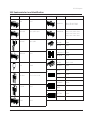
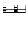
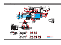
1
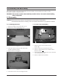
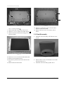
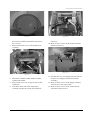
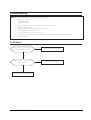
COLOR MONITOR
SyncMaster 320TFT/520TFT
SERVICE
Manual
COLOR MONITOR
CONTENTS
1. Precautions
2. Reference Information
3. Product Specifications
4. Operating Instructions
5. Disassembly & Reassembly
6. Troubleshooting
7. Exploded View & Parts List
8. Block Diagram
**
9. Electrical Parts List
10. PCB Diagrams
11. Wiring Diagram
12. Schematic Diagrams
1 Precautions
Follow these safety, servicing and ESD precautions to prevent damage and to protect against potential hazards such as
electrical shock.
1-1 Safety Precautions
1-1-1 Warnings
1.
For continued safety, do not attempt to modify the
circuit board.
2.
Disconnect the AC power and DC Power Jack
before servicing.
3.
(READING SHOULD
NOT BE ABOVE 0.5mA)
When the chassis is operating, semiconductor
heatsinks are potential shock hazards.
TEST ALL
EXPOSED METAL
SURFACES
1-1-2 Servicing the LCD Monitor
1.
2.
1-1-3 Fire and Shock Hazard
Before returning the monitor to the user, perform the
following safety checks:
1.
Inspect each lead dress to make certain that the
leads are not pinched or that hardware is not
lodged between the chassis and other metal parts in
the monitor.
2.
Inspect all protective devices such as nonmetallic
control knobs, insulating materials, cabinet backs,
adjustment and compartment covers or shields,
isolation resistor-capacitor networks, mechanical
insulators, etc.
3.
2-WIRE CORD
When servicing the LCD Monitor, remove the static
charge by connecting a 10k ohm resistor in series
with an insulated wire (such as a test probe)
between the chassis and the anode lead.
(Disconnect the AC line cord from the AC outlet.)
It is essential that service technicians have an
accurate voltage meter available at all times. Check
the calibration of this meter periodically.
Leakage Current Hot Check (Figure 1-1): WARNING:
Do not use an isolation transformer during this test.
Use a leakage current tester or a metering system
that complies with American National Standards
Institute (ANSI C101.1, Leakage Current for
Appliances), and Underwriters Laboratories (UL
Publication UL1410, 59.7).
SyncMaster 320TFT/520TFT
LEAKAGE
CURRENT
TESTER
DEVICE
UNDER
TEST
ALSO TEST WITH
PLUG REVERSED
(USING AC ADAPTER
PLUG AS REQUIRED)
EARTH
GROUND
Figure 1-1. Leakage Current Test Circuit
4.
With the unit completely reassembled, plug the AC
line cord directly into a 120V AC outlet. With the
unitÕs AC switch first in the ON position and then
OFF, measure the current between a known earth
ground (metal water pipe, conduit, etc.) and all
exposed metal parts, including: metal cabinets,
screwheads and control shafts. The current
measured should not exceed 0.5 milliamp. Reverse
the power-plug prongs in the AC outlet and repeat
the test.
1-1-4 Product Safety Notices
Some electrical and mechanical parts have special
safety-related characteristics which are often not
evident from visual inspection. The protection they give
may not be obtained by replacing them with
components rated for higher voltage, wattage, etc. Parts
that have special safety characteristics are identified by
! on schematics and parts lists. A substitute
replacement that does not have the same safety
characteristics as the recommended replacement part
might create shock, fire and / or other hazards. Product
safety is under review continuously and new
instructions are issued whenever appropriate.
1-1
1 Precautions
1-2 Servicing Precautions
WARNING:
An electrolytic capacitor installed with the wrong polarity might explode.
Caution:
Before servicing units covered by this service manual, read and follow the Safety Precautions
section of this manual.
Note:
If unforeseen circumstances create conflict between the following servicing precautions and any of the
safety precautions, always follow the safety precautions.
1-2-1 General Servicing Precautions
1.
2.
3.
Always unplug the unitÕs AC power cord from the
AC power source and disconnect the DC Power
Jack before attempting to:
(a) remove or reinstall any component or assembly,
(b) disconnect PCB plugs or connectors, (c) connect
a test component in parallel with an electrolytic
capacitor.
Some components are raised above the printed
circuit board for safety. An insulation tube or tape
is sometimes used. The internal wiring is
sometimes clamped to prevent contact with
thermally hot components. Reinstall all such
elements to their original position.
4.
Check the insulation between the blades of the AC
plug and accessible conductive parts (examples:
metal panels, input terminals and earphone jacks).
5.
Insulation Checking Procedure: Disconnect the
power cord from the AC source and turn the power
switch ON. Connect an insulation resistance meter
(500 V) to the blades of the AC plug.
The insulation resistance between each blade of the
AC plug and accessible conductive parts (see
above) should be greater than 1 megohm.
6.
After servicing, always check that the screws,
components and wiring have been correctly
reinstalled. Make sure that the area around the
serviced part has not been damaged.
Always connect a test instrumentÕs ground lead to
the instrument chassis ground before connecting the
positive lead; always remove the instrumentÕs
ground lead last.
1-3 Electrostatically Sensitive Devices (ESD) Precautions
Some semiconductor (solid state) devices can be easily damaged by static electricity. Such components are commonly
called Electrostatically Sensitive Devices (ESD). Examples of typical ESD devices are integrated circuits and some fieldeffect transistors. The following techniques will reduce the incidence of component damage caused by static electricity.
1.
Immediately before handling any semiconductor
components or assemblies, drain the electrostatic
charge from your body by touching a known earth
ground. Alternatively, wear a discharging wriststrap device. To avoid a shock hazard, be sure to
remove the wrist strap before applying power to
the monitor.
6.
Do not remove a replacement ESD from its
protective package until you are ready to install it.
Most replacement ESDs are packaged with leads
that are electrically shorted together by conductive
foam, aluminum foil or other conductive materials.
7.
2.
After removing an ESD-equipped assembly, place it
on a conductive surface such as aluminum foil to
prevent accumulation of an electrostatic charge.
Immediately before removing the protective
material from the leads of a replacement ESD,
touch the protective material to the chassis or
circuit assembly into which the device will be
installed.
3.
Do not use freon-propelled chemicals. These can
generate electrical charges sufficient to damage
ESDs.
Caution: Be sure no power is applied to the
chassis or circuit and observe all
other safety precautions.
4.
Use only a grounded-tip soldering iron to solder or
desolder ESDs.
5.
Use only an anti-static solder removal device. Some
solder removal devices not classified as Òanti-staticÓ
can generate electrical charges sufficient to damage
ESDs.
1-2
8.
Minimize body motions when handling
unpackaged replacement ESDs. Motions such as
brushing clothes together, or lifting your foot from
a carpeted floor can generate enough static
electricity to damage an ESD.
SyncMaster 320TFT/520TFT
2 Reference Information
2-1 List of Abbreviations, Symbols and Acronyms
2-1-1 Abbreviations
Abbreviation
AUTO_MENB
AUTO_SOG
BL_EN
BRIGHT
DAB(7:0)
DAG(7:0)
DAR(7:0)
DBB(7:0)
DBG(7:0)
DBR(7:0)
DDC_SCL
DDC_SDA
DEN
DFSYNCB
DHCLK
DHS
DREFCLK1
DV_BLU
DV_FBK
DV_GRN
DV_RED
DVACTIV1B
DVCLK
DVS
DVSYNCB
FSD(47:0)
HSYNC_PLL
INVERT
KEY1
KEY2
LED
LEFT
LVDS_DATA
LVDS_EN
M_HSYNC
M_HSYNC1
M_VSYNC
M_VSYNC1
OSCOUT
Definition
AUTO ENABLE (NEG.)
SINK ON GREEN ENABLE
LCD PANEL BACK LIGHT ENABLE
BRIGHTNESS CONTROL
BLUE COLOR DATA (ODD) FROM IC305
GREEN COLOR DATA (ODD) FROM IC305
RED COLOR DATA (ODD) FROM IC305
BLUE COLOR DATA (EVEN) FROM IC305
GREEN COLOR DATA (EVEN) FROM IC305
RED COLOR DATA (EVEN) FROM IC305
DDC I2C CLOCK FROM PC
DDC I2C DATA FROM PC
LVDS DATA ENABLE
CONTROL SIGNAL FROM IC301 TO IC305
DOT CLOCK FOR PANEL DRIVING
LVDS HSYNC
67MHz OSC CLK FOR IC305
OSD BLUE DATA
OSD ENABLE
OSD GREEN DATA
OSD RED DATA
HSYNC FOR OSD (NEG.)
DOT CLOCK FOR OSD
LVDS VSYNC
VSYNC FOR OSD (NEG.)
VIDEO DATA BETWEEN IC301 AND
IC302,IC303,IC304
HSYNC FOR PLL
INTERLACE CONTROL SIGNAL
FUNCTION KEY SIGNAL1 TO MICOM
FUNCTION KEY SIGNAL2 TO MICOM
LED ON
LEFT CHANNEL AUDIO INPUT SIGNAL
DATA OUTPUT FROM IC310, IC311
LVDS ENABLE
BUFFERED MICOM OUTPUT HSYNC
MICOM OUTPUT HSYNC
BUFFERED MICOM OUTPUT VSYNC
MICOM OUTPUT VSYNC
BUFFERED 24MHz CLOCK
SyncMaster 320TFT/520TFT
Abbreviation
OSCOUT1
PANEL_EN
PC_BLUE_IN
PC_GREEN_IN
PC_HSYNC_IN
PC_RED_IN
PC_VSYNC_IN
PCBLUE(7:0)
PCCLAMP
PCCLAMP1
PCCLK
PCCLK2
PCCLK3
PCGREEN(7:0)
PCRED(7:0)
PCVSYNC2
RESETB
RGB_HSYNC
RGB_VSYNC
RIGHT
SCL
SCSB
SDA
SOG_CSYNC
SOURCE_PC
SPI_MISO
SPI_MOSI
SPI_SCK
SW_REG_ENB
VAIL_CSB
VCBLNKB
VCC
VCLREQB
VDD
VGABLUE(7:0)
VGAGREEN(7:0)
VGARED(7:0)
VGBBLUE(7:0)
VGBGREEN(7:0)
VGBRED(7:0)
Definition
24MHz CLOCK
+12V_PANEL/+5V_PANEL ENABLE
BLUE COLOR SIGNAL FROM PC
GREEN COLOR SIGNAL FROM PC
HSYNC FROM PC
RED COLOR SIGNAL FROM PC
VSYNC FROM PC
BLUE COLOR DATA FROM IC101
BUFFERED VIDEO CLAMP SIGNAL
VIDEO CLAMP SIGNAL
PLL CLOCK OUT FOR IC301
PLL CLOCK OUT FOR IC405
PLL CLOCK OUT FOR IC110
GREEN COLOR DATA FROM ADC(IC101)
RED COLOR DATA FROM IC101
BUFFERED VSYNC
RESET (NEG.)
HSYNC FOR MICOM(IC401)
VSYNC FOR MICOM(IC401)
RIGHT CHANNEL AUDIO INPUT SIGNAL
I2C CLOCK
IC305 ENABLE
I2C DATA
COMPOSITE SYNC FROM SOG
SELF RASTER CHECK SIGNAL
SERIAL INPUT DATA CONTROL
SERIAL OUTPUT DATA CONTROL
SERIAL CLOCK
POWER ON/OFF CONTROL
IC301 ENABLE
CONTROL SIGNAL FROM IC305 TO IC301
DC 5V FOR MICOM(IC401)
CONTROL SIGNAL FROM IC305 TO IC301
AUDIO DC 5V POWER
NC
NC
NC
BLUE COLOR DATA FROM IC301
GREEN COLOR DATA FROM IC301
RED COLOR DATA FROM IC301
2-1
2 Reference Information
2-1-2 Symbols
Hot Ground
Cold Ground
!
Provides special safety considerations
2-1-2 Acronyms
Acronym
Definition
Acronym
Definition
ABL
Automatic Brightness Limits
H/V
Horizontal/Vertical
AC
Alternating Current
HV
High Voltage
ACL
Automatic Contrast Limit
I/O
Input/Output
AFC
Automatic Frequency Control
IC
Integrated Circuit
ANSI
American National Standards Institute
LED
Light Emitting Diode
CMOS
Complementary Metal Oxide
Semiconductor
MAC
Macintosh
MOFA
Mask Outside Frame Assembly
CRT
Cathode Ray Tube
OCP
Over Current Protection
DC
Direct Current
OP AMP
Operational Amplifier
DDC
Data Display Channel
OSD
On Screen Display
DF
Dynamic Focus
P-P
Peak to Peak
DMM
Digital Multimeter
PCB
Printed Circuit Board
DPMS
Display Power Management Signaling
PLL
Phase Locked Loop
DVM
Digital Voltmeter
PWM
Pulse Width Modulation
DY
Deflection Yoke
SMPS
Switch Mode Power Supply
EEPROM
Electrically Erasable and
Programmable Read only Memory
SVGA
Super Video Graphics Array
TP
Test Point
ESD
Electrostatically Sensitive Device
UL
Underwriters Laboratories
ESF
Electronic Static Field
USB
Universal Serial Bus
FBT
Flyback Transformer
VESA
FET
Field Effect Transistor
Video Electronics Standard
Association
FH
Horizontal Frequency
VGA
Video Graphics Array
FS
Fail Safe
VR
Variable Registor
FV
Vertical Frequency
W/B
White Balance
GD
Geometric Distortion
2-2
SyncMaster 320TFT/520TFT
3 Product Specifications
3-1 Specifications
Item
Description
LCD Panel
TFT-LCD panel, RGB vertical stripe, normaly white, 15-Inch viewable,
0.297 (H) x 0.297 (V) pixel pitch, 13.3-Inch viewable, 0.264 (H) x 0.264 (V) pixel pitch
Scanning Frequency
Horizontal : 30 kHz to 61 kHz (Automatic)
Vertical : 50 Hz to 75 Hz (Automatic)
Display Colors
16.7 Million colors
Maximum Resolution
Horizontal : 1024 Pixels
Vertical : 768 Pixels
Input Video Signal
Analog, 0.714 Vp-p ± 5% positive at 75 Ω, internally terminated
Input Sync Signal
Type:
Level:
Seperate H/V sync, Composite H/V, Sync-on-Green, automatic synchronization
without external switch of sync type
TTL level
Maximum Pixel Clock rate
80 MHz
Active Display
Horizontal/Vertical
13.3”: 270.3 mm / 207.8 mm
15”: 304.1 mm / 228.1 mm
AC power voltage & Frequency AC 90 to 264 Volts, 60/ 50 Hz ± 3 Hz
Power Consumption
13.3”: 40 W (max.), 15”: 45 W (max.)
Dimensions
Unit (W x D x H)
Carton (W x D x H)
13.3”
15”
13.9x7.7x15.6 Inches (354.3 x 195.6 x 395 mm) 15.9x7.7x16.5 Inches (404 x 196.6 x 418.7 mm)
17.9 x 11.1 x 19.2 Inches (455 x 282 x 488 mm) 18.7 x 11.1 x 20.1 Inches (475 x 282 x 510 mm)
Weight
(Net/Gross)
13.3”: 6.4 kg / 8.0 kg, 15”: 7.5 kg / 9.5 kg
Environmental Considerations
Operating Temperature : 50°F to 104°F (10°C to 40°C)
Humidity : 10 % to 80 %
Storage Temperature
: -13°F to 113°F (-25°C to 45°C)
Humidity : 5 % to 95 %
Audio Characteristics
• Audio Characteristics
• Built-in Microphone: High-sensitivity condenser microphone (mono)
• Audio input: Left/Right Stereo phone jack, 0.7 Vrms
• Sound output: 1 W (left) + 1 W (right)/THD 1% at 8ohm
• Frequency response: 80 Hz~20 kHz (at –3dB)
• Headphone: Max 50mW output (3.5-pi jack)
• Speaker: Internal semi Dome (8ohm x 2)
• SyncMaster 320TFT/520TFT complies with SWEDAC (MPR II) recommendations for reduced electromagnetic fields.
• Designs and specifications are subject to change without prior notice.
SyncMaster 320TFT/520TFT
3-1
3 Product Specifications
3-2 Pin Assignments
Sync
Type
15-Pin Signal Cable Connector
Separate
Pin No.
1
2
3
4
5
6
7
8
9
10
11
12
13
14
15
Red
Green
Blue
GND
GND (DDC Return)
GND-R
GND-G
GND-B
No Connection
GND-Sync/Self Test
GND
DDC Data
H-Sync
V-Sync
DDC Clock
Sync
Type
Pin No.
1
2
3
4
5
6
7
8
9
10
11
12
13
14
15
16 ~26
3-2
Composite
Red
Green
Blue
GND
GND (DDC Return)
GND-R
GND-G
GND-B
No Connection
GND-Sync/Self Test
GND
DDC Data
H/V-Sync
Not Used
DDC Clock
Sync-on-green
Red
Green + H/V Sync
Blue
GND
GND (DDC Return)
GND-R
GND-G
GND-B
Not Used
GND-Sync/Self Test
GND
DDC Data
Not Used
Not Used
DDC Clock
26-Pin Signal Cable Connector
Separate
Red
Green
Blue
GND
GND (DDC Return)
GND-R
GND-G
GND-B
No Connection
GND-Sync/Self Test
GND
DDC Data
H-Sync
V-Sync
DDC Clock
GND
Composite
Red
Green
Blue
GND
GND (DDC Return)
GND-R
GND-G
GND-B
No Connection
GND-Sync/Self Test
GND
DDC Data
H/V-Sync
Not Used
DDC Clock
GND
Sync-on-green
Red
Green + H/V Sync
Blue
GND
GND (DDC Return)
GND-R
GND-G
GND-B
Not Used
GND-Sync/Self Test
GND
DDC Data
Not Used
Not Used
DDC Clock
GND
SyncMaster 320TFT/520TFT
3 Product Specifications
3-3 Timing Chart
This section of the service manual describes the timing that the computer industry recognizes as standard
for computer-generated video signals.
Table 3-1. Timing Chart
Mode
IBM
VESA
VGA1/70 Hz
640 x 350
VGA2/70 Hz
720 x 400
VGA3/60 Hz
640 x 480
640/72 Hz
640 x 480
640/75 Hz
640 x 480
800/56 Hz
800 x 600
800/60 Hz
800 x 600
fH (kHz)
31.469
31.469
31.469
37.861
37.500
35.156
37.879
A µsec
31.778
31.777
31.778
26.413
26.667
28.444
26.400
B µsec
3.813
3.813
3.813
1.270
2.032
2.000
3.200
C µsec
1.589
1.589
1.589
3.810
3.810
3.556
2.200
D µsec
26.058
26.058
26.058
20.825
20.317
22.222
20.000
E µsec
0.318
0.318
0.318
0.508
0.508
0.667
1.000
fV (Hz)
70.086
70.087
59.940
72.809
75.000
56.250
60.317
O msec
14.268
14.268
16.683
13.735
13.333
17.778
16.579
P msec
0.064
0.064
0.064
0.079
0.080
0.057
0.106
Q msec
1.716
0.858
0.794
0.528
0.427
0.626
0.607
R msec
11.504
13.155
15.761
13.100
12.800
17.067
15.840
S msec
0.985
0.191
0.064
0.026
0.027
0.028
0.026
25.175
28.322
25.175
31.500
31.500
36.000
40.000
Polarity
H.Sync
Positive
Negative
Negative
Negative
Negative
Positive
Positive
V.Sync
Negative
Positive
Negative
Negative
Negative
Negative
Positive
Remark
Separate
Separate
Separate
Separate
Separate
Separate
Separate
Timing
Clock
Frequency
(MHz)
Separate Sync
Horizontal
Vertical
Video
Video
Video
Video
CC
DD
E E
Q
RR
Q
S S
Sync
Sync
Sync
Sync
BB
PP
AA
O O
A : Line time total
B : Horizontal sync width
O : Frame time total
P : Vertical sync width
C : Back porch
D : Active time
Q : Back porch
R : Active time
E : Front porch
SyncMaster 320TFT/520TFT
S : Front porch
3-3
3 Product Specifications
Table 3-1. Timing Chart Continued
Mode
MAC.
VESA
800/72 Hz
800 x 600
800/75 Hz
800 x 600
1024/60 Hz
1024 x 768
1024/70 Hz
1024 x 768
1024/75 Hz
1024 x 768
640/67 Hz
60 x 480
832/75 Hz
832 x 624
fH (kHz)
48.077
46.875
48.363
56.476
60.023
35.000
49.726
A µsec
20.800
21.333
20.677
17.707
16.660
28.571
20.110
B µsec
2.400
1.616
2.092
1.813
1.219
2.116
1.117
C µsec
1.280
3.232
2.462
1.920
2.235
3.175
3.910
D µsec
16.000
16.162
15.754
13.653
13.003
21.164
14.524
E µsec
1.120
0.323
0.369
0.320
0.203
2.116
0.559
fV (Hz)
72.188
75.000
60.004
70.069
75.029
66.667
74.551
O msec
13.853
13.333
16.666
14.272
13.328
15.000
13.414
P msec
0.125
0.064
0.124
0.106
0.050
0.086
0.060
Q msec
0.478
0.448
0.600
0.513
0.466
1.114
0.784
R msec
12.480
12.800
15.880
13.599
12.795
13.714
12.549
S msec
0.770
0.021
0.062
0.053
0.017
0.086
0.020
50.000
49.500
65.000
75.000
78.750
30.240
57.284
Polarity
H.Sync
Positive
Positive
Negative
Negative
Positive
Negative
Negative
V.Sync
Positive
Positive
Negative
Negative
Positive
Negative
Negative
Remark
Separate
Separate
Separate
Separate
Separate
Separate
Separate
Timing
Clock
Frequency
(MHz)
Separate Sync
Horizontal
Vertical
Video
Video
Video
Video
CC
DD
E E
Q
RR
Q
S S
Sync
Sync
Sync
Sync
BB
PP
AA
O O
A : Line time total
B : Horizontal sync width
O : Frame time total
P : Vertical sync width
C : Back porch
D : Active time
Q : Back porch
R : Active time
E : Front porch
3-4
S : Front porch
SyncMaster 320TFT/520TFT
4 Opearating Instructions
4-1 Control and Connectors
Audio in port
MIC
AUDIO
OUT
IN
Headphone jack
External microphone jack
Microphone out port
Power port
1
Figure 4-2. Rear View
EXIT
MENU
3
Table 4-1. Front Panel Controls
2
Location
ON/OFF
VOLUME
TREBLE
BASS
4
MIN
5
MAX MIN
MAX
6
MIN
MAX
7
1
MIC
ON
Symbol
OFF
8
9
Description
Power Button
2
MENU
Menu Button
3
EXIT
Exit Button
4
Up / Down / + / – Buttons
10
ON/OFF
VOLUME
5
Figure 4-1. Front View and Control
Audio On / Off & Volume Buttons
MIN
MAX
BASS
6
Bass Button
MIN
MAX
TREBLE
7
Treble Button
MIN
MAX
MIC
8
Microphone On / Off Button
ON
SyncMaster 320TFT/520TFT
OFF
9
Microphone
10
Amplified Stereo Speakers
4-1
4 Operating Instructions
4-2 Microprocessor Controls and Functions
This monitor has no Òservice onlyÓ micom
controls. Should there be a problem with the
microprocessor, replace the entire circuit board.
There are, however, user accessible adjustment
features that are described below.
This monitor has factory preset display settings
for each of the signals listed in the standard
display modes Timing Chart (see pages 3-3 and
3-4). As a result, when the monitor senses one of
the standard signal timings, it automatically
adjusts to an optimum size and position.
However, the user may wish to adjust the monitor
to their own preferred settings rather than use
those preset at the factory. The monitor saves up
to 16 user defined settings.
4-2-1 OSD Window
The adjustable features described below all use
the on-screen menu system.
1. Push the ↵ button to open the display the onscreen menu.
2. Use the
or
button to change an
adjustment icon, use the ↵ button to highlight
an adjustment icon, then use the + or Ð
buttons to make the adjustments.
3. To select another adjustment on the same
screen, use the
or
button to move to the
next selection.
4. When you are done making adjustments on an
adjustment icon, push the EXIT button.
5. When you are done making all adjustments,
push the EXIT button.
Table 4-2 shows the adjustment types and their
icons.
Table 4-2. Available adjustments
Icon
Description
Adjustment Range
IBM
Image Lock
Fine
Coarse
4-2
VGA1/70 Hz
0-100
740-860
VGA2/70 Hz
0-100
840-960
VGA3/60 Hz
0-100
740-860
VESA SVGA/56 Hz
0-100
964-1084
SVGA/60 Hz
0-100
996-1116
XGA/60 Hz
0-100
1284-1404
Icon
Description
Position
Horizontal
Vertical
Auto Reset
Auto Adjustment
Geometry
Color
Image Size
Zoom
Display Size
Brightness
0 ~ 100
Contrast
0 ~ 100
Misc.
Language
Menu Position
Menu Display Time
Display Mode
Color Control
Red
Green
Blue
0 ~ 100
0 ~ 100
0 ~ 100
Color Temperature
Mode1
Mode2
Mode3
Adjustment Range
0 ~ 100
0 ~ 100
No/Yes
No/Yes
No/Yes
x1, x2, x4, x8
Normal/Expand
0 ~ 100
0 ~ 100
SyncMaster 320TFT/520TFT
4 Operating Instructions
4-3 Audio Controls
Your LCD monitor provides four audio control buttons located on the front of the stand.
4-3-1 Audio Adjustments
To access the on/off, volume, bass and treble functions push the appropriate blue control button until it
pops out then turn it to the right or left to adjust the function.
Function
Name
Audio On/Off
and Volume
Bass
Treble
Effect of Control Movement
Left
Right
Off
On
Decrease volume
Increase volume
Decrease Low sounds
Increase low sounds
Decrease high sounds
Increase High sounds
Your LCD monitor includes an internal microphone which you can turn On or Off using the rightmost
control of the Audio controls.
Function
Name
Audio On/Off
and Volume
SyncMaster 320TFT/520TFT
Effect of Control Movement
In
Out
Off
On
4-3
4 Operating Instructions
4-4 Power Management System
This monitor has a built-in power management
system called PowerSaver. This system saves
energy by switching your monitor into an off
mode when it has not been used for an certain
amount of time.
Note 1: This monitor automatically returns to
normal operation when horizontal and
vertical sync return. This occurs when you
move the computer's mouse or press a key
on the keyboard.
This system operates with a VESA DPMS
compliant video card installed in your computer.
You use a software utility installed on your
computer to set up this feature. See the table
below for details.
Note 2: This monitor is EPA ENERGY STAR¨
compliant and NUTEK compliant when
used with a computer equipped with
VESA DPMS functionality. If your
computer system cannot support a display
power management function, you can
purchase an optional DPMS software
program to enable the power saving
function. Please contact Samsung or your
dealer for more information.
Table 4-3. Display Power Management Signaling (DPMS); 13.3”
State
Items
Normal
Operation
Power saving function EPA/NUTEK
Stand-By
Mode
Suspend Mode Power Off Mode
Position A
Position B
Horizontal Sync
Active
Inactive
Active
Inactive
Vertical Sync
Active
Active
Inactive
Inactive
Video
Active
Blanked
Power
Indicator
Green
Amber
Blanked
Amber
Blinking
(0.5 sec)
Blanked
Amber
Blinking
(1 sec)
Less than
5W
Less than
5W
40 W (max.)
Power
30 W
Consumption/hr
(nominal)
Less than
5W
Note 3: For energy conservation, turn your
monitor OFF when it is not needed, or
when leaving it unattended for long
periods.
Note 4: Audio Part is operated separately by
control button.
Table 4-4. Display Power Management Signaling (DPMS); 15”
State
Items
Normal
Operation
Power saving function EPA/NUTEK
Stand-By
Mode
Suspend Mode Power Off Mode
Position A
Position B
Horizontal Sync
Active
Inactive
Active
Inactive
Vertical Sync
Active
Active
Inactive
Inactive
Video
Active
Blanked
Power
Indicator
Green
Amber
Blanked
Amber
Blinking
(0.5 sec)
Blanked
Amber
Blinking
(1 sec)
Less than
5W
Less than
5W
45 W (max.)
Power
35 W
Consumption/hr
(nominal)
4-4
Less than
5W
SyncMaster 320TFT/520TFT
5 Disassembly and Reassembly
This section of the service manual describes the disassembly and reassembly procedures for the
SyncMaster 320TFT/520TFT monitors.
WARNING: This monitor contains electrostatically sensitive devices. Use caution when handling
these components.
5-1 Disassembly
Cautions:1. Disconnect the monitor from the power source before disassembly.
2. Follow these directions carefully; never use metal instruments to pry apart the cabinet.
5-1-1 Removing the Stand
5-1-2 Front Cover Disassembly
1. Remove 2 hinge caps on the Rear Cover.
2. Remove 4 screws in the hinge area.
Figure 5-3
Figure 5-1
3. Push the Stand to the left and remove the
Stand from Body (Front).
4. Remove the Cover Signal.
1. Remove the 4 screws on Rear Cover.
(Point ; )
2. Remove Rear Cover from Front Cover.
3. Remove 6 Main PCB screws on Rear Panel
Bracket. (Point ; )
4. Disconnect Main PCB, Inverter wire, Function
wire and Interface wire.
5. Remove Main PCB Assembly.
Figure 5-2
5. Disconnect Power Cord and Signal Cable.
SyncMaster 320TFT/520TFT
5-1
5 Disassembly and Reassembly
Figure 5-6
Figure 5-4
6. Remove 4 screws on the Rear Panel Bracket.
(15Ó : 6 screws)- Point;
14. Remove 2 connecting screws between Rear
Bracket and Inverter PCB.
7. Remove Bracket Panel from Front Cover.
8. Remove 1 screw on the Power PCB. (Point;
9. Remove Function PCB from locking area of
Function Knob.
)
15. Remove Interface wire on the Rear side of
Panel.
5-1-3 Stand Disassembly
1. Stand the stand assembly with the base close
to you.
Figure 5-5
10. Remove 4 screws on the Front Bracket Panel.
Figure 5-7
11. Remove Front Bracket Panel.
12. Disconnect jack between Panel and Inverter
PCB.
2. Remove the 4 screws on the back cover of the
stand and remove it.
13. Remove Rear Bracket Panel.
3. Stand the stand assembly upside down.
5-2
SyncMaster 320TFT/520TFT
5 Disassembly and Reassembly
Figure 5-8
4. Rotate the stand base smoothly so that 2 screw
holes match with the stand base and remove
the 2 screws.
5. Remove the Back Cover of the Stand Front
assembly.
Figure 5-10
9. Remove the 4 screws on the SMPS PCB and
remove it.
10. Remove the 2 screws on the Audio Function
PCB and remove it.
Figure 5-11
Figure 5-9
6. Disconnect CN804, CN806, CN814, CN815,
CN816 and CN805.
11. Pull the tabs of Cover Hinge outward and lift
off the Cover Hinge from the Stand Front
assembly.
7. Remove the one screw of signal cable on the
stand base.
12. Remove the 4 screws on the Hinge assembly
and remove it and signal cable.
8. Lift off the back side of the stand front
assembly and pull it toward the stand base.
13. Remove the 2 screws on the Audio PCB of
stand base and remove it.
SyncMaster 320TFT/520TFT
5-3
5 Disassembly and Reassembly
5-2 Replacement Order of Lamp Assemblies (13.3”)
1. Disconnect lamp leadconnector from the inverter.
* Replacement of lamp assemblies
should be done at the power off
state and recommended clean
bench condition.
2. Remove a screw which is
used to hold a lamp
assembly on.
3. Replace lamp assemblies.
4. Assemble new lamp
assembly according to the
counter order.
5-4
SyncMaster 320TFT/520TFT
5 Disassembly and Reassembly
5-3 Replacement Order of Lamp Assemblies (15”)
1. Disconnect lamp leadconnectors from the inverter.
(2EA)
* Replacement of lamp assemblies
should be done at the power off
state and recommended clean
bench condition.
2. Remove 2 screws which are
used to hold the lamp
assemblies on.
3. Replace 2 lamp assemblies.
4. Assemble new lamp
assemblies according to the
counter order.
SyncMaster 320TFT/520TFT
5-5
5 Disassembly and Reassembly
5-4 Reassembly
Reassembly procedures are in the reverse order of Disassembly procedures.
5-6
SyncMaster 320TFT/520TFT
6 Troubleshooting
Notes: 1. Before troubleshooting, setup the PC’s display as below.
• Resolution: 1024 x 768
• H-frequency: 48 kHz
• V-frequency: 60 Hz
2. If no picture appears, make sure the power cord is correctly connected.
3. Check the following circuits.
• No raster appears: Audio PCB, SMPS PCB, Main PCB
• 12V develop but no screen: Main PCB
• 12V does not develop: Audio PCB, SMPS PCB
4. If you push and hold the “EXIT” button for more than 5 seconds, the monitor automatically turns back
to the factory preset.
6-1 No Power
Does proper DC 12 V appear at
DC jack connected to CN102?
No
Check SMPS PCB and CN816.
Yes
Does proper DC 5 V appear at
Pin 3 of IC109?
No
Check F101 and IC109.
Yes
Check IC401, RL101, D110 and Q101.
SyncMaster 320TFT/520TFT
6-1
6 Troubleshooting
6-2 No Video
Power indicator is green
Does the clock pulse
appear at output of
FT110, FT111, FT112?
No
7
Does the H-sync pulse appear
at Pin 94 of IC101?
No
8
9
Does the pulse appear at Pin 10
of IC105 or Pin 1 of IC104?
No
Yes
Yes
Replace IC106.
Yes
Replace IC105 (seperate sync)
or IC104 (SOG).
Replace IC101.
18 19
Does the sync pulses appear at
Pins 13 and 14 of IC110?
No
20
1
Does the sync pulses appear at
Pins 2 and 3 of IC110?
No
Check IC401 and IC101.
Yes
Yes
2
3
4
Replace IC110 or check its
related circuit.
5
Do the sync pulses appear at
Pins 22, 23, 25 and 26 of IC310?
No
10
11
12
13
14
Do the sync pulses appear at Pins
2, 3, 54, 55 and 56 of IC301?
No
Replace IC301 or check its
related circuit.
Yes
Yes
6
Do the waveforms appear at
Pins 5 and 20 of CN301?
Replace IC305 or check its
related circuit.
No
Replace IC310 and IC311 or
check its related circuits.
Yes
Replace LCD Panel
6-2
SyncMaster 320TFT/520TFT
6 Troubleshooting
WAVEFORMS
1 IC110 #3
CH1 RMS = 3.6 V
5 IC310 #26
CH1 RMS = 2.12 V
2 IC310 #22
CH1 RMS = 3.1 V
6 CN301 #5~20
CH1 RMS = 2.3 V
7 IC101 #94
4 IC310 #25
CH1 RMS = 2.8 V
8 IC105 #10
CH1 RMS = 3.5 V
CH1 RMS = 3.1 V
10 IC301 #2
11 IC301 #3
12 IC301 #54
CH1 RMS = 4.56 V
CH1 RMS = 2.3 V
CH1 RMS = 3.25 V
CH1 RMS = 2.35 V
13 IC301, #55
14 IC301 #56
18 IC110 #13
19 IC110 #14
CH1 RMS = 200 mV
CH1 RMS = 50 mV
CH1 RMS = 1.24 V
CH1 RMS = 400 mV
9 IC104, #1
CH1 RMS = 1.18 V
3 IC310 #23
20 IC110 #2
CH1 RMS = 4.4 V
SyncMaster 320TFT/520TFT
6-3
6 Troubleshooting
6-3 No Video of Alternate Vertical Line
One or more even or odd vertical lines do not display.
6
Does the waveform appear
at Pin 20 of CN301?
No
WAVEFORMS
Replace IC311 or check its
related circuit.
6 CN301 #5~20
Yes
Replace LCD panel.
CH1 RMS = 1.18 V
6-4 No OSD
WAVEFORMS
There is video but no OSD.
15
While pushing a front control
button does any pulse appear
at Pin 12 of IC307?
15 IC307 #12
No
16
Do sync signals appear at Pins 5
and 10 of IC307?
17
No
CH1 RMS = 2.2 V
Yes
Yes
16 IC307 #5
Replace IC307 or check its
related circuit.
Replace IC308.
Check IC306 and related circuits.
CH1 RMS = 1.7 V
17 IC307 #10
CH1 RMS = 4.3 V
6-5 User Controls Don’t Work
Does the DC level change at
Pins 11 and 12 of IC401 when you
push the front panel button?
No
Check the buttons.
(SW861 ~ SW866)
Yes
Go to 6-4 No OSD Display.
6-4
SyncMaster 320TFT/520TFT
6 Troubleshooting
6-6 No Sound
Does the DC 5 V appear at Pin
5 of CN806, Pin 4 of IC803?
No
Check IC804, IC803, VR841 and
related circuit.
No
Check Pins 1 and 2 of CN806 and
related circuits.
Yes
Does the sound input signal
appear at Pins 6 and 11 of IC803?
Yes
Do the sound signals appear at
Pins 3 and 14 of IC803?
No
Check IC803 and related circuits.
Yes
Does the DC 2.5 V bias appear at
Pin 16 of IC503?
No
Check CN813, ZD803, R821, R822,
C815 on the Audio PCB.
Yes
Check CN814, CN815 outputs.
SyncMaster 320TFT/520TFT
6-5
6 Troubleshooting
6-7 Microphones Don’t Work
Does the PC’s sound
program operate well?
No
Check the PC’s sound program
and compatibility.
No
Connect the cable between the PC
and monitor.
No
Check the connection between
CN805 on the Audio PCB and the
Internal Microphone.
Yes
Is the connection between the PC
and monitor secure?
Yes
Is the Internal Microphone
connector attached?
Yes
Does the Internal Microphone
work?
No
Check Q802 and related circuits.
Yes
Does the External Microphone
work?
No
Check the CN182 jack.
Yes
OK
6-8 Headphones Don’t Work
Can you hear any sound from
the Headphones?
No
Check CN813 on the Audio PCB
and related circuit R817, R820,
ZD801, ZD802.
No
Check the Headphone Plug in the
Headphone Jack and R821, R822,
C815 on the Audio PCB.
Yes
Do you hear sound from the
Internal Speaker?
Yes
OK
6-6
SyncMaster 320TFT/520TFT
9 Electrical Parts List
9 Electrical Parts List
9-1 Main PCB Parts
Loc. No.
BD101
BD102
BD103
BD104
BD105
C100
C101
C102
C103
C104
C105
C106
C107
C108
C109
C110
C111
C112
C113
C114
C115
C116
C117
C118
C119
C120
C121
C122
C123
C124
C125
C126
C127
C128
C129
C130
C131
C132
C133
C134
C135
C136
C137
C138
C139
Code No.
2703-001334
2703-001334
2703-001334
2703-001334
2703-001334
2203-000260
2402-000168
2203-000260
2402-000168
2203-000260
2402-000168
2402-000168
2203-000239
2203-000239
2203-000260
2203-000203
2203-000203
2203-000203
2203-000203
2203-000203
2404-000123
2203-000260
2203-000203
2203-000260
2203-000203
2203-000260
2203-000203
2203-000260
2203-000609
2203-000260
2203-000609
2203-000260
2203-000609
2203-000137
2203-000260
2203-000260
2203-000260
2203-000260
2203-000260
2203-000260
2203-000260
2203-000260
2203-000203
2203-000260
2203-000203
SyncMaster 320TFT/520TFT
Description
INDUCTOR-SMD
INDUCTOR-SMD
INDUCTOR-SMD
INDUCTOR-SMD
INDUCTOR-SMD
C-CERAMIC,CHIP
C-AL,SMD
C-CERAMIC,CHIP
C-AL,SMD
C-CERAMIC,CHIP
C-AL,SMD
C-AL,SMD
C-CERAMIC,CHIP
C-CERAMIC,CHIP
C-CERAMIC,CHIP
C-CERAMIC,CHIP
C-CERAMIC,CHIP
C-CERAMIC,CHIP
C-CERAMIC,CHIP
C-CERAMIC,CHIP
C-TA,CHIP
C-CERAMIC,CHIP
C-CERAMIC,CHIP
C-CERAMIC,CHIP
C-CERAMIC,CHIP
C-CERAMIC,CHIP
C-CERAMIC,CHIP
C-CERAMIC,CHIP
C-CERAMIC,CHIP
C-CERAMIC,CHIP
C-CERAMIC,CHIP
C-CERAMIC,CHIP
C-CERAMIC,CHIP
C-CERAMIC,CHIP
C-CERAMIC,CHIP
C-CERAMIC,CHIP
C-CERAMIC,CHIP
C-CERAMIC,CHIP
C-CERAMIC,CHIP
C-CERAMIC,CHIP
C-CERAMIC,CHIP
C-CERAMIC,CHIP
C-CERAMIC,CHIP
C-CERAMIC,CHIP
C-CERAMIC,CHIP
Specification
Remarks
1.5uH,10%,2x1.25x0.85mm
1.5uH,10%,2x1.25x0.85mm
1.5uH,10%,2x1.25x0.85mm
1.5uH,10%,2x1.25x0.85mm
1.5uH,10%,2x1.25x0.85mm
10nF,10%,50V,X7R,TP,2012
100uF,20%,16V,TP,8x6.3
10nF,10%,50V,X7R,TP,2012
100uF,20%,16V,TP,8x6.3
10nF,10%,50V,X7R,TP,2012
100uF,20%,16V,TP,8x6.3
100uF,20%,16V,TP,8x6.3
100pF,5%,50V,NPO,TP,2012
100pF,5%,50V,NPO,TP,2012
10nF,10%,50V,X7R,TP,2012
100nF,10%,16V,X7R,TP,2012
100nF,10%,16V,X7R,TP,2012
100nF,10%,16V,X7R,TP,2012
100nF,10%,16V,X7R,TP,2012
100nF,10%,16V,X7R,TP,2012
10uF,20%,16V,TP,6032,2.9mm
10nF,10%,50V,X7R,TP,2012
100nF,10%,16V,X7R,TP,2012
10nF,10%,50V,X7R,TP,2012
100nF,10%,16V,X7R,TP,2012
10nF,10%,50V,X7R,TP,2012
100nF,10%,16V,X7R,TP,2012
10nF,10%,50V,X7R,TP,2012
22nF,10%,50V,X7R,TP,2012
10nF,10%,50V,X7R,TP,2012
22nF,10%,50V,X7R,TP,2012
10nF,10%,50V,X7R,TP,2012
22nF,10%,50V,X7R,TP,2012
1.5nF,10%,50V,NPO,TP,2012
10nF,10%,50V,X7R,TP,2012
10nF,10%,50V,X7R,TP,2012
10nF,10%,50V,X7R,TP,2012
10nF,10%,50V,X7R,TP,2012
10nF,10%,50V,X7R,TP,2012
10nF,10%,50V,X7R,TP,2012
10nF,10%,50V,X7R,TP,2012
10nF,10%,50V,X7R,TP,2012
100nF,10%,16V,X7R,TP,2012
10nF,10%,50V,X7R,TP,2012
100nF,10%,16V,X7R,TP,2012
9-1
9 Electrical Parts List
Loc. No.
C140
C141
C142
C143
C144
C145
C146
C147
C148
C149
C150
C151
C152
C153
C154
C155
C156
C157
C158
C159
C160
C161
C163
C165
C166
C167
C168
C169
C170
C172
C173
C174
C175
C176
C177
C180
C181
C182
C183
C184
C185
C186
C187
C188
C189
C190
C195
9-2
Code No.
2203-000260
2203-000203
2203-000844
2203-000953
2203-000203
2203-000260
2203-000260
2203-000203
2203-000260
2203-000203
2203-000260
2203-000203
2203-000595
2203-000595
2203-000595
2203-000595
2203-001002
2203-000203
2203-000203
2402-000168
2203-000203
2203-000203
2203-000260
2404-000256
2409-001004
2402-000168
2203-000260
2402-000168
2203-000260
2402-000168
2409-001004
2404-000123
2404-000123
2402-000168
2409-001004
2404-000123
2404-000123
2203-000260
2203-000203
2203-000260
2203-000203
2404-000123
2404-000123
2203-000203
2203-000260
2203-000203
2203-000260
Description
C-CERAMIC,CHIP
C-CERAMIC,CHIP
C-CERAMIC,CHIP
C-CERAMIC,CHIP
C-CERAMIC,CHIP
C-CERAMIC,CHIP
C-CERAMIC,CHIP
C-CERAMIC,CHIP
C-CERAMIC,CHIP
C-CERAMIC,CHIP
C-CERAMIC,CHIP
C-CERAMIC,CHIP
C-CERAMIC,CHIP
C-CERAMIC,CHIP
C-CERAMIC,CHIP
C-CERAMIC,CHIP
C-CERAMIC,CHIP
C-CERAMIC,CHIP
C-CERAMIC,CHIP
C-AL,SMD
C-CERAMIC,CHIP
C-CERAMIC,CHIP
C-CERAMIC,CHIP
C-TA,CHIP
C-ORGANIC
C-AL,SMD
C-CERAMIC,CHIP
C-AL,SMD
C-CERAMIC,CHIP
C-AL,SMD
C-ORGANIC
C-TA,CHIP
C-TA,CHIP
C-AL,SMD
C-ORGANIC
C-TA,CHIP
C-TA,CHIP
C-CERAMIC,CHIP
C-CERAMIC,CHIP
C-CERAMIC,CHIP
C-CERAMIC,CHIP
C-TA,CHIP
C-TA,CHIP
C-CERAMIC,CHIP
C-CERAMIC,CHIP
C-CERAMIC,CHIP
C-CERAMIC,CHIP
Specification
Remarks
10nF,10%,50V,X7R,TP,2012
100nF,10%,16V,X7R,TP,2012
39nF,10%,50V,X7R,TP,2012
470pF,5%,50V,NPO,TP,2012
100nF,10%,16V,X7R,TP,2012
10nF,10%,50V,X7R,TP,2012
10nF,10%,50V,X7R,TP,2012
100nF,10%,16V,X7R,TP,2012
10nF,10%,50V,X7R,TP,2012
100nF,10%,16V,X7R,TP,2012
10nF,10%,50V,X7R,TP,2012
100nF,10%,16V,X7R,TP,2012
220pF,5%,50V,NPO,TP,2012
220pF,5%,50V,NPO,TP,2012
220pF,5%,50V,NPO,TP,2012
220pF,5%,50V,NPO,TP,2012
47pF,5%,50V,NPO,TP,2012
100nF,10%,16V,X7R,TP,2012
100nF,10%,16V,X7R,TP,2012
100uF,20%,16V,TP,8x6.3
100nF,10%,16V,X7R,TP,2012
100nF,10%,16V,X7R,TP,2012
10nF,10%,50V,X7R,TP,2012
47uF,20%,16V,TP,7343,7.3mm
100uF,20%,16V,LL,BK,8x10.5mm,3
100uF,20%,16V,TP,8x6.3
10nF,10%,50V,X7R,TP,2012
100uF,20%,16V,TP,8x6.3
10nF,10%,50V,X7R,TP,2012
100uF,20%,16V,TP,8x6.3
100uF,20%,16V,LL,BK,8x10.5mm,3
10uF,20%,16V,TP,6032,2.9mm
10uF,20%,16V,TP,6032,2.9mm
100uF,20%,16V,TP,8x6.3
100uF,20%,16V,LL,BK,8x10.5mm,3
10uF,20%,16V,TP,6032,2.9mm
10uF,20%,16V,TP,6032,2.9mm
10nF,10%,50V,X7R,TP,2012
100nF,10%,16V,X7R,TP,2012
10nF,10%,50V,X7R,TP,2012
100nF,10%,16V,X7R,TP,2012
10uF,20%,16V,TP,6032,2.9mm
10uF,20%,16V,TP,6032,2.9mm
100nF,10%,16V,X7R,TP,2012
10nF,10%,50V,X7R,TP,2012
100nF,10%,16V,X7R,TP,2012
10nF,10%,50V,X7R,TP,2012
SyncMaster 320TFT/520TFT
9 Electrical Parts List
Loc. No.
C196
C201
C202
C203
C204
C301
C302
C303
C304
C305
C306
C307
C308
C309
C310
C311
C312
C313
C314
C315
C316
C317
C318
C319
C320
C321
C322
C323
C324
C325
C326
C327
C328
C329
C330
C331
C332
C333
C334
C335
C336
C337
C338
C339
C340
C341
C342
Code No.
2203-000260
2203-000455
2203-000203
2203-000455
2203-000203
2203-000203
2203-000203
2203-000203
2203-000203
2203-000203
2203-000203
2203-000203
2203-000203
2203-000203
2203-000203
2203-000203
2203-000203
2203-000203
2203-000203
2203-000203
2203-000203
2203-000203
2203-000203
2203-000203
2203-000203
2203-000203
2203-000203
2203-001723
2203-000203
2203-000203
2203-000203
2203-000203
2203-000203
2203-000203
2203-000203
2203-000203
2203-000203
2203-000203
2203-000203
2203-000203
2203-000203
2203-000203
2203-000203
2203-000203
2203-000203
2203-000203
2203-000203
SyncMaster 320TFT/520TFT
Description
C-CERAMIC,CHIP
C-CERAMIC,CHIP
C-CERAMIC,CHIP
C-CERAMIC,CHIP
C-CERAMIC,CHIP
C-CERAMIC,CHIP
C-CERAMIC,CHIP
C-CERAMIC,CHIP
C-CERAMIC,CHIP
C-CERAMIC,CHIP
C-CERAMIC,CHIP
C-CERAMIC,CHIP
C-CERAMIC,CHIP
C-CERAMIC,CHIP
C-CERAMIC,CHIP
C-CERAMIC,CHIP
C-CERAMIC,CHIP
C-CERAMIC,CHIP
C-CERAMIC,CHIP
C-CERAMIC,CHIP
C-CERAMIC,CHIP
C-CERAMIC,CHIP
C-CERAMIC,CHIP
C-CERAMIC,CHIP
C-CERAMIC,CHIP
C-CERAMIC,CHIP
C-CERAMIC,CHIP
C-CERAMIC,CHIP
C-CERAMIC,CHIP
C-CERAMIC,CHIP
C-CERAMIC,CHIP
C-CERAMIC,CHIP
C-CERAMIC,CHIP
C-CERAMIC,CHIP
C-CERAMIC,CHIP
C-CERAMIC,CHIP
C-CERAMIC,CHIP
C-CERAMIC,CHIP
C-CERAMIC,CHIP
C-CERAMIC,CHIP
C-CERAMIC,CHIP
C-CERAMIC,CHIP
C-CERAMIC,CHIP
C-CERAMIC,CHIP
C-CERAMIC,CHIP
C-CERAMIC,CHIP
C-CERAMIC,CHIP
Specification
Remarks
10nF,10%,50V,X7R,TP,2012
1nF,5%,50V,NPO,TP,2012
100nF,10%,16V,X7R,TP,2012
1nF,5%,50V,NPO,TP,2012
100nF,10%,16V,X7R,TP,2012
100nF,10%,16V,X7R,TP,2012
100nF,10%,16V,X7R,TP,2012
100nF,10%,16V,X7R,TP,2012
100nF,10%,16V,X7R,TP,2012
100nF,10%,16V,X7R,TP,2012
100nF,10%,16V,X7R,TP,2012
100nF,10%,16V,X7R,TP,2012
100nF,10%,16V,X7R,TP,2012
100nF,10%,16V,X7R,TP,2012
100nF,10%,16V,X7R,TP,2012
100nF,10%,16V,X7R,TP,2012
100nF,10%,16V,X7R,TP,2012
100nF,10%,16V,X7R,TP,2012
100nF,10%,16V,X7R,TP,2012
100nF,10%,16V,X7R,TP,2012
100nF,10%,16V,X7R,TP,2012
100nF,10%,16V,X7R,TP,2012
100nF,10%,16V,X7R,TP,2012
100nF,10%,16V,X7R,TP,2012
100nF,10%,16V,X7R,TP,2012
100nF,10%,16V,X7R,TP,2012
100nF,10%,16V,X7R,TP,2012
4.7pF,5%,50V,NPO,TP,2012
100nF,10%,16V,X7R,TP,2012
100nF,10%,16V,X7R,TP,2012
100nF,10%,16V,X7R,TP,2012
100nF,10%,16V,X7R,TP,2012
100nF,10%,16V,X7R,TP,2012
100nF,10%,16V,X7R,TP,2012
100nF,10%,16V,X7R,TP,2012
100nF,10%,16V,X7R,TP,2012
100nF,10%,16V,X7R,TP,2012
100nF,10%,16V,X7R,TP,2012
100nF,10%,16V,X7R,TP,2012
100nF,10%,16V,X7R,TP,2012
100nF,10%,16V,X7R,TP,2012
100nF,10%,16V,X7R,TP,2012
100nF,10%,16V,X7R,TP,2012
100nF,10%,16V,X7R,TP,2012
100nF,10%,16V,X7R,TP,2012
100nF,10%,16V,X7R,TP,2012
100nF,10%,16V,X7R,TP,2012
9-3
9 Electrical Parts List
Loc. No.
C343
C344
C345
C346
C347
C348
C349
C350
C351
C352
C353
C354
C355
C356
C357
C358
C359
C360
C361
C362
C363
C364
C365
C366
C367
C368
C369
C370
C371
C372
C373
C374
C377
C378
C379
C380
C381
C382
C383
C384
C385
C386
C387
C388
C389
C390
C391
9-4
Code No.
2203-000203
2203-000203
2203-000203
2203-000203
2203-000203
2203-000203
2203-000203
2203-000203
2203-000203
2203-000203
2203-000203
2203-000203
2203-000203
2203-000203
2203-000203
2203-000203
2203-000203
2203-000203
2203-000203
2203-000203
2203-000203
2404-000123
2203-000203
2203-000203
2203-000818
2203-000818
2404-000151
2404-000151
2404-000123
2203-000260
2404-000123
2203-000203
2404-000123
2203-000260
2404-000123
2203-000260
2404-000123
2203-000260
2404-000123
2203-000260
2404-000123
2203-000260
2404-000123
2203-000260
2203-000203
2203-000203
2203-000455
Description
C-CERAMIC,CHIP
C-CERAMIC,CHIP
C-CERAMIC,CHIP
C-CERAMIC,CHIP
C-CERAMIC,CHIP
C-CERAMIC,CHIP
C-CERAMIC,CHIP
C-CERAMIC,CHIP
C-CERAMIC,CHIP
C-CERAMIC,CHIP
C-CERAMIC,CHIP
C-CERAMIC,CHIP
C-CERAMIC,CHIP
C-CERAMIC,CHIP
C-CERAMIC,CHIP
C-CERAMIC,CHIP
C-CERAMIC,CHIP
C-CERAMIC,CHIP
C-CERAMIC,CHIP
C-CERAMIC,CHIP
C-CERAMIC,CHIP
C-TA,CHIP
C-CERAMIC,CHIP
C-CERAMIC,CHIP
C-CERAMIC,CHIP
C-CERAMIC,CHIP
C-TA,CHIP
C-TA,CHIP
C-TA,CHIP
C-CERAMIC,CHIP
C-TA,CHIP
C-CERAMIC,CHIP
C-TA,CHIP
C-CERAMIC,CHIP
C-TA,CHIP
C-CERAMIC,CHIP
C-TA,CHIP
C-CERAMIC,CHIP
C-TA,CHIP
C-CERAMIC,CHIP
C-TA,CHIP
C-CERAMIC,CHIP
C-TA,CHIP
C-CERAMIC,CHIP
C-CERAMIC,CHIP
C-CERAMIC,CHIP
C-CERAMIC,CHIP
Specification
Remarks
100nF,10%,16V,X7R,TP,2012
100nF,10%,16V,X7R,TP,2012
100nF,10%,16V,X7R,TP,2012
100nF,10%,16V,X7R,TP,2012
100nF,10%,16V,X7R,TP,2012
100nF,10%,16V,X7R,TP,2012
100nF,10%,16V,X7R,TP,2012
100nF,10%,16V,X7R,TP,2012
100nF,10%,16V,X7R,TP,2012
100nF,10%,16V,X7R,TP,2012
100nF,10%,16V,X7R,TP,2012
100nF,10%,16V,X7R,TP,2012
100nF,10%,16V,X7R,TP,2012
100nF,10%,16V,X7R,TP,2012
100nF,10%,16V,X7R,TP,2012
100nF,10%,16V,X7R,TP,2012
100nF,10%,16V,X7R,TP,2012
100nF,10%,16V,X7R,TP,2012
100nF,10%,16V,X7R,TP,2012
100nF,10%,16V,X7R,TP,2012
100nF,10%,16V,X7R,TP,2012
10uF,20%,16V,TP,6032,2.9mm
100nF,10%,16V,X7R,TP,2012
100nF,10%,16V,X7R,TP,2012
33pF,5%,50V,NPO,TP,2012
33pF,5%,50V,NPO,TP,2012
1uF,20%,16V,TP,3216
1uF,20%,16V,TP,3216
10uF,20%,16V,TP,6032,2.9mm
10nF,10%,50V,X7R,TP,2012
10uF,20%,16V,TP,6032,2.9mm
100nF,10%,16V,X7R,TP,2012
10uF,20%,16V,TP,6032,2.9mm
10nF,10%,50V,X7R,TP,2012
10uF,20%,16V,TP,6032,2.9mm
10nF,10%,50V,X7R,TP,2012
10uF,20%,16V,TP,6032,2.9mm
10nF,10%,50V,X7R,TP,2012
10uF,20%,16V,TP,6032,2.9mm
10nF,10%,50V,X7R,TP,2012
10uF,20%,16V,TP,6032,2.9mm
10nF,10%,50V,X7R,TP,2012
10uF,20%,16V,TP,6032,2.9mm
10nF,10%,50V,X7R,TP,2012
100nF,10%,16V,X7R,TP,2012
100nF,10%,16V,X7R,TP,2012
1nF,5%,50V,NPO,TP,2012
SyncMaster 320TFT/520TFT
9 Electrical Parts List
Loc. No.
C392
C393
C394
C395
C396
C397
C398
C401
C402
C403
C404
C405
C406
C407
C408
C409
C410
C411
C412
C413
C414
C415
C416
C417
C418
C419
CFT302
CFT317
CFT318
CFT319
CIS
CL101
CL102
CN101
CN102
CN103
CN103_PANEL
CN301
CN301_PANEL
CN401
CN401_CN861
D101
D102
D103
D104
Code No.
2203-000203
2203-000455
2203-000203
2203-000455
2203-000203
2203-000455
2203-000203
2203-000260
2404-000123
2203-000260
2404-000123
2203-000455
2404-000123
2203-000203
2402-000168
2404-000123
2203-000260
2203-000203
2404-000123
2203-000555
2203-000555
2404-000123
2203-000260
2203-000239
2203-000260
2404-000123
2901-001115
2901-001112
2901-001115
2901-001112
BN13-10001D
BN27-20001C
BN27-20001A
3701-001117
3722-000117
3711-000556
BN39-40001B
BN39-40001G
3711-003161
BN39-40001K
BN39-40001J
3711-001031
BN39-40001E
0401-000191
0401-000191
0401-000191
0401-000191
SyncMaster 320TFT/520TFT
Description
C-CERAMIC,CHIP
C-CERAMIC,CHIP
C-CERAMIC,CHIP
C-CERAMIC,CHIP
C-CERAMIC,CHIP
C-CERAMIC,CHIP
C-CERAMIC,CHIP
C-CERAMIC,CHIP
C-TA,CHIP
C-CERAMIC,CHIP
C-TA,CHIP
C-CERAMIC,CHIP
C-TA,CHIP
C-CERAMIC,CHIP
C-AL,SMD
C-TA,CHIP
C-CERAMIC,CHIP
C-CERAMIC,CHIP
C-TA,CHIP
C-CERAMIC,CHIP
C-CERAMIC,CHIP
C-TA,CHIP
C-CERAMIC,CHIP
C-CERAMIC,CHIP
C-CERAMIC,CHIP
C-TA,CHIP
FILTER-EMI SMD
FILTER-EMI SMD
FILTER-EMI SMD
FILTER-EMI SMD
IC-HYBRID/INVERTER
COIL-SMD
COIL-CHOKE
CONNECTOR-DSUB
JACK-DC POWER
CONNECTOR-HEADER
CBF-HARNESS
CBF-HARNESS
CONNECTOR-HEADER
CBF-HARNESS
CBF-HARNESS
CONNECTOR-HEADER
CBF-HARNESS
DIODE-SWITCHING
DIODE-SWITCHING
DIODE-SWITCHING
DIODE-SWITCHING
Specification
100nF,10%,16V,X7R,TP,2012
1nF,5%,50V,NPO,TP,2012
100nF,10%,16V,X7R,TP,2012
1nF,5%,50V,NPO,TP,2012
100nF,10%,16V,X7R,TP,2012
1nF,5%,50V,NPO,TP,2012
100nF,10%,16V,X7R,TP,2012
10nF,10%,50V,X7R,TP,2012
10uF,20%,16V,TP,6032,2.9mm
10nF,10%,50V,X7R,TP,2012
10uF,20%,16V,TP,6032,2.9mm
1nF,5%,50V,NPO,TP,2012
10uF,20%,16V,TP,6032,2.9mm
100nF,10%,16V,X7R,TP,2012
100uF,20%,16V,TP,8x6.3
10uF,20%,16V,TP,6032,2.9mm
10nF,10%,50V,X7R,TP,2012
100nF,10%,16V,X7R,TP,2012
10uF,20%,16V,TP,6032,2.9mm
20pF,5%,50V,NPO,TP,2012
20pF,5%,50V,NPO,TP,2012
10uF,20%,16V,TP,6032,2.9mm
10nF,10%,50V,X7R,TP,2012
100pF,5%,50V,NPO,TP,2012
10nF,10%,50V,X7R,TP,2012
10uF,20%,16V,TP,6032,2.9mm
50VDC,500mADC,20pF,3.1x
50VDC,1.0ADC,85pF+-20%
50VDC,500mADC,20pF,3.1x
50VDC,1.0ADC,85pF+-20%
LXB310T,SIC180,IN
105UH,20%,SMD,TAPING
53.0UH,20%,DR10*5,TRAY
26P,2R,FEMALE,ANGLE,AU
3P,3.5mm,AG,BLK,NO
BOX,12P,1R,1.25mm,SMD-A
12P/6P,100MM,BLU/WHT/BLK,UL1
12P,200MM,BLU/WHT/RED.UL1571
BOX,20P,1R,1.25mm,ANGLE
20P,200MM,BLK,UL2835,AWG28(2
20P,170MM,BLK,UL2835,AWG28-20C
BOX,6P,1R,2.50mm,ANGLE
6P,280MM,BLK,UL2464,AWG24-6C
MMBD4148,50V,DL-35,TP
MMBD4148,50V,DL-35,TP
MMBD4148,50V,DL-35,TP
MMBD4148,50V,DL-35,TP
Remarks
13.3”
15”
13.3”
15”
9-5
9 Electrical Parts List
Loc. No.
D105
D106
D109
D110
D113
D114
D401
D402
D403
D404
F101
FT101
FT102
FT103
FT120
FT122
FT301
FT306
FT307
FT308
FT309
FT310
FT311
FT312
FT313
FT314
FT315
FT316
FT320
FT321
FT322
FT323
FT324
FT325
FT326
FT327
FT328
FT329
FT330
FT331
FT332
FT333
FT334
FT335
FT390
FT404
IC101
9-6
Code No.
Description
0401-000191
0401-000191
0401-000191
0401-000191
0402-000016
0402-000016
0401-000191
0401-000191
0401-000191
0401-000191
3601-001061
2901-001114
2901-001114
2901-001114
2901-001114
2901-000172
2901-001114
2901-001114
2901-001114
2901-001114
2901-001114
2901-001114
2901-001114
2901-001114
2901-001114
2901-001114
2901-001114
2901-001114
2901-001113
2901-001113
2901-001113
2901-001113
2901-001113
2901-001113
2901-001113
2901-001113
2901-001113
2901-001113
2901-001113
2901-001113
2901-001113
2901-001113
2901-001113
2901-001113
2901-001114
2901-001114
1002-001099
DIODE-SWITCHING
DIODE-SWITCHING
DIODE-SWITCHING
DIODE-SWITCHING
DIODE-RECTIFIER
DIODE-RECTIFIER
DIODE-SWITCHING
DIODE-SWITCHING
DIODE-SWITCHING
DIODE-SWITCHING
FUSE-SMD
FILTER-EMI SMD
FILTER-EMI SMD
FILTER-EMI SMD
FILTER-EMI SMD
FILTER-EMI ON BOARD
FILTER-EMI SMD
FILTER-EMI SMD
FILTER-EMI SMD
FILTER-EMI SMD
FILTER-EMI SMD
FILTER-EMI SMD
FILTER-EMI SMD
FILTER-EMI SMD
FILTER-EMI SMD
FILTER-EMI SMD
FILTER-EMI SMD
FILTER-EMI SMD
FILTER-EMI SMD
FILTER-EMI SMD
FILTER-EMI SMD
FILTER-EMI SMD
FILTER-EMI SMD
FILTER-EMI SMD
FILTER-EMI SMD
FILTER-EMI SMD
FILTER-EMI SMD
FILTER-EMI SMD
FILTER-EMI SMD
FILTER-EMI SMD
FILTER-EMI SMD
FILTER-EMI SMD
FILTER-EMI SMD
FILTER-EMI SMD
FILTER-EMI SMD
FILTER-EMI SMD
IC-A/D CONVERTER
Specification
Remarks
MMBD4148,50V,DL-35,TP
MMBD4148,50V,DL-35,TP
MMBD4148,50V,DL-35,TP
MMBD4148,50V,DL-35,TP
UF5404,400V,3A,DO-201AD
UF5404,400V,3A,DO-201AD
MMBD4148,50V,DL-35,TP
MMBD4148,50V,DL-35,TP
MMBD4148,50V,DL-35,TP
MMBD4148,50V,DL-35,TP
125V,10A,FAST ACTING,CERAMIC,6
25VDC,2.0ADC,100nF,3.2x
25VDC,2.0ADC,100nF,3.2x
25VDC,2.0ADC,100nF,3.2x
25VDC,2.0ADC,100nF,3.2x
50V,10A,-,12x11x13
25VDC,2.0ADC,100nF,3.2x
25VDC,2.0ADC,100nF,3.2x
25VDC,2.0ADC,100nF,3.2x
25VDC,2.0ADC,100nF,3.2x
25VDC,2.0ADC,100nF,3.2x
25VDC,2.0ADC,100nF,3.2x
25VDC,2.0ADC,100nF,3.2x
25VDC,2.0ADC,100nF,3.2x
25VDC,2.0ADC,100nF,3.2x
25VDC,2.0ADC,100nF,3.2x
25VDC,2.0ADC,100nF,3.2x
25VDC,2.0ADC,100nF,3.2x
25VDC,0.2A,35pF+-20%,2x
25VDC,0.2A,35pF+-20%,2x
25VDC,0.2A,35pF+-20%,2x
25VDC,0.2A,35pF+-20%,2x
25VDC,0.2A,35pF+-20%,2x
25VDC,0.2A,35pF+-20%,2x
25VDC,0.2A,35pF+-20%,2x
25VDC,0.2A,35pF+-20%,2x
25VDC,0.2A,35pF+-20%,2x
25VDC,0.2A,35pF+-20%,2x
25VDC,0.2A,35pF+-20%,2x
25VDC,0.2A,35pF+-20%,2x
25VDC,0.2A,35pF+-20%,2x
25VDC,0.2A,35pF+-20%,2x
25VDC,0.2A,35pF+-20%,2x
25VDC,0.2A,35pF+-20%,2x
25VDC,2.0ADC,100nF,3.2x
25VDC,2.0ADC,100nF,3.2x
TDA8752,8BIT,QFP,100P
SyncMaster 320TFT/520TFT
9 Electrical Parts List
Loc. No.
IC102
IC103
IC104
IC105
IC106
IC107
IC108
IC109
IC110
IC115
IC301
IC302
IC303
IC304
IC305
IC306
IC307
IC308
IC309
IC310
IC311
IC401
IC401_SOCK
IC402
IC403
IC404
IC405
IC406
IC803
IC804
L102
L151
L152
L153
L160
L170
L171
L172
L301
L302
L303
L403
L406
L407
Q101
Q301
Q302
Code No.
1203-000001
1203-000001
1204-000292
0803-000117
0803-000122
1203-001448
1203-001447
1203-000001
BN13-10001B
1203-001538
1205-001407
1105-001165
1105-001165
1105-001165
0904-001222
0801-000757
1204-001251
0802-001038
0505-001170
1003-001023
1003-001023
0903-001063
3704-001071
1203-001109
1103-001009
1103-001086
BN13-10001A
0803-000122
1201-001269
1203-001161
2703-001070
2703-001070
2703-001070
2703-001070
2703-001070
2703-001070
2703-001070
2703-001070
2703-001070
2703-001070
2703-001070
2703-001070
2703-001070
2703-001070
0504-000152
0501-000342
0501-000342
SyncMaster 320TFT/520TFT
Description
IC-POSI.FIXED REG.
IC-POSI.FIXED REG.
IC-VIDEO SYSTEM
IC-TTL
IC-TTL
IC-POSI.FIXED REG.
IC-POSI.FIXED REG.
IC-POSI.FIXED REG.
IC-ASIC
IC-POSI.ADJUST REG.
IC-BUFFER
IC-DRAM
IC-DRAM
IC-DRAM
IC-GRAPHIC CONT.
IC-CMOS LOGIC
IC-OSD PROCESSOR
IC-BICMOS LOGIC
FET-SILICON
IC-VFD
IC-VFD
IC-MICROCONTROLLER
SOCKET-IC
IC-VOL. DETECTOR
IC-EEPROM
IC-EEPROM
IC-ASIC
IC-TTL
IC-AUDIO AMP
IC-POSI.FIXED REG.
INDUCTOR-SMD
INDUCTOR-SMD
INDUCTOR-SMD
INDUCTOR-SMD
INDUCTOR-SMD
INDUCTOR-SMD
INDUCTOR-SMD
INDUCTOR-SMD
INDUCTOR-SMD
INDUCTOR-SMD
INDUCTOR-SMD
INDUCTOR-SMD
INDUCTOR-SMD
INDUCTOR-SMD
TR-DIGITAL
TR-SMALL SIGNAL
TR-SMALL SIGNAL
Specification
Remarks
7805,TO-220,3P,PLAS
7805,TO-220,3P,PLAS
LM1881M,SOP,8P,150MIL,PL
74F14,INVERTER,SOP,14P,150MIL
74F125,BUFFER,SOP,14P,150MIL,Q
2596,TO-263,5P,PLAS
2596,TO-263,5P,PLAS
7805,TO-220,3P,PLAS
LXB530T,DLY-D1,SOP,16P,H/V POS
431,SOT-89,3P,PLAS
GMFC1,QFP,208P,PLASTIC,3.6V
416S1020B,2x512Kx16BIT,SOP,50P
416S1020B,2x512Kx16BIT,SOP,50P
416S1020B,2x512Kx16BIT,SOP,50P
GMZ1,QFP,208P,65MHz
74FCT244,BUFFER,SOP,20P,30
MC141544DWR2,SOP,24P,15
74FCT573T,TRANSPARENT LA
SI9933ADY-T1,P,-20V,3.4A,0.0
DS90CF561,DIP,48P,600MIL,SINGL
DS90CF561,DIP,48P,600MIL,SINGL
72E75,8BIT,DIP,42P,60
42P,DIP,SN,1.778mm
7045,SOT-89,3P,PLASTI
24LC211,128X8BIT,DIP,8P,300MIL
24LC08B,256x8BIT,DIP,8P,300MIL
LXB320T,A40MX04-PL44C,PLCC,44P
74F125,BUFFER,SOP,14P,150MIL,Q
4863,DIP,16P,300MIL,DUAL
2576,TO-220,5P,PLAS
100uH,10%,4.5x3.2x3.2mm
100uH,10%,4.5x3.2x3.2mm
100uH,10%,4.5x3.2x3.2mm
100uH,10%,4.5x3.2x3.2mm
100uH,10%,4.5x3.2x3.2mm
100uH,10%,4.5x3.2x3.2mm
100uH,10%,4.5x3.2x3.2mm
100uH,10%,4.5x3.2x3.2mm
100uH,10%,4.5x3.2x3.2mm
100uH,10%,4.5x3.2x3.2mm
100uH,10%,4.5x3.2x3.2mm
100uH,10%,4.5x3.2x3.2mm
100uH,10%,4.5x3.2x3.2mm
100uH,10%,4.5x3.2x3.2mm
KSR2101,PNP,200MW,4.7K-4.7K,S
KSC1623-Y,NPN,200mW,SOTKSC1623-Y,NPN,200mW,SOT-
9-7
9 Electrical Parts List
Loc. No.
Q401
R101
R102
R103
R104
R105
R106
R107
R110
R115
R116
R117
R118
R124
R125
R127
R128
R129
R130
R131
R132
R134
R135
R137
R138
R140
R190
R191
R192
R193
R194
R301
R302
R303
R305
R306
R307
R308
R309
R310
R311
R312
R316
R317
R401
R402
R403
9-8
Code No.
0501-000342
2007-001166
2007-001166
2007-001166
2007-000781
2007-000781
2007-000781
2007-000493
2007-000290
2007-000593
2007-000593
2007-001118
2007-000593
2007-000593
2007-000593
2007-000300
2007-000290
2007-000822
2007-000290
2007-000290
2007-000029
2007-000300
2007-000029
2007-000872
2007-000872
2007-000029
2007-000029
2007-000029
2007-001113
2007-000029
2007-000872
2007-000468
2007-000468
2007-000290
2007-000300
2007-000290
2007-000290
2007-000282
2007-000282
2007-000300
2007-000282
2007-000300
2007-000766
2007-000572
2007-000941
2007-000941
2007-000941
Description
TR-SMALL SIGNAL
R-CHIP
R-CHIP
R-CHIP
R-CHIP
R-CHIP
R-CHIP
R-CHIP
R-CHIP
R-CHIP
R-CHIP
R-CHIP
R-CHIP
R-CHIP
R-CHIP
R-CHIP
R-CHIP
R-CHIP
R-CHIP
R-CHIP
R-CHIP
R-CHIP
R-CHIP
R-CHIP
R-CHIP
R-CHIP
R-CHIP
R-CHIP
R-CHIP
R-CHIP
R-CHIP
R-CHIP
R-CHIP
R-CHIP
R-CHIP
R-CHIP
R-CHIP
R-CHIP
R-CHIP
R-CHIP
R-CHIP
R-CHIP
R-CHIP
R-CHIP
R-CHIP
R-CHIP
R-CHIP
Specification
Remarks
KSC1623-Y,NPN,200mW,SOT75ohm,5%,1/10W,DA,TP,2012
75ohm,5%,1/10W,DA,TP,2012
75ohm,5%,1/10W,DA,TP,2012
33ohm,5%,1/10W,DA,TP,2012
33ohm,5%,1/10W,DA,TP,2012
33ohm,5%,1/10W,DA,TP,2012
2.2Kohm,5%,1/10W,DA,TP,2012
100ohm,5%,1/10W,DA,TP,2012
22ohm,5%,1/10W,DA,TP,2012
22ohm,5%,1/10W,DA,TP,2012
680ohm,5%,1/10W,DA,TP,2012
22ohm,5%,1/10W,DA,TP,2012
22ohm,5%,1/10W,DA,TP,2012
22ohm,5%,1/10W,DA,TP,2012
10Kohm,5%,1/10W,DA,TP,2012
100ohm,5%,1/10W,DA,TP,2012
390ohm,5%,1/10W,DA,TP,2012
100ohm,5%,1/10W,DA,TP,2012
100ohm,5%,1/10W,DA,TP,2012
0ohm,5%,1/10W,DA,TP,2012
10Kohm,5%,1/10W,DA,TP,2012
0ohm,5%,1/10W,DA,TP,2012
4.7Kohm,5%,1/10W,DA,TP,2012
4.7Kohm,5%,1/10W,DA,TP,2012
0ohm,5%,1/10W,DA,TP,2012
0ohm,5%,1/10W,DA,TP,2012
0ohm,5%,1/10W,DA,TP,2012
680Kohm,5%,1/10W,DA,TP,2012
0ohm,5%,1/10W,DA,TP,2012
4.7Kohm,5%,1/10W,DA,TP,2012
1Kohm,5%,1/10W,DA,TP,2012
1Kohm,5%,1/10W,DA,TP,2012
100ohm,5%,1/10W,DA,TP,2012
10Kohm,5%,1/10W,DA,TP,2012
100ohm,5%,1/10W,DA,TP,2012
100ohm,5%,1/10W,DA,TP,2012
100Kohm,5%,1/10W,DA,TP,2012
100Kohm,5%,1/10W,DA,TP,2012
10Kohm,5%,1/10W,DA,TP,2012
100Kohm,5%,1/10W,DA,TP,2012
10Kohm,5%,1/10W,DA,TP,2012
330ohm,5%,1/10W,DA,TP,2012
220ohm,5%,1/10W,DA,TP,2012
47Kohm,5%,1/10W,DA,TP,2012
47Kohm,5%,1/10W,DA,TP,2012
47Kohm,5%,1/10W,DA,TP,2012
SyncMaster 320TFT/520TFT
9 Electrical Parts List
Loc. No.
R404
R405
R406
R407
R408
R409
R410
R411
R412
R413
R415
R416
R417
R418
R419
R420
R421
R422
R423
R424
R425
R426
R427
R429
R431
R432
R433
R436
R437
R438
R439
R440
R441
R442
R443
R444
R445
R447
R448
R449
R450
R451
R452
R455
R456
R457
R458
Code No.
2007-000941
2007-000941
2007-000941
2007-000941
2007-000941
2007-000941
2007-000872
2007-000872
2007-000941
2007-000941
2007-000941
2007-000941
2007-000290
2007-000290
2007-000290
2007-000290
2007-000290
2007-000290
2007-000290
2007-000290
2007-000290
2007-000290
2007-000300
2007-000290
2007-000401
2007-000290
2007-000290
2007-000290
2007-000290
2007-000290
2007-000290
2007-000290
2007-000290
2007-000290
2007-000290
2007-000290
2007-000290
2007-000290
2007-000290
2007-000468
2007-000686
2007-000686
2007-000468
2007-000477
2007-000572
2007-000290
2007-000290
SyncMaster 320TFT/520TFT
Description
R-CHIP
R-CHIP
R-CHIP
R-CHIP
R-CHIP
R-CHIP
R-CHIP
R-CHIP
R-CHIP
R-CHIP
R-CHIP
R-CHIP
R-CHIP
R-CHIP
R-CHIP
R-CHIP
R-CHIP
R-CHIP
R-CHIP
R-CHIP
R-CHIP
R-CHIP
R-CHIP
R-CHIP
R-CHIP
R-CHIP
R-CHIP
R-CHIP
R-CHIP
R-CHIP
R-CHIP
R-CHIP
R-CHIP
R-CHIP
R-CHIP
R-CHIP
R-CHIP
R-CHIP
R-CHIP
R-CHIP
R-CHIP
R-CHIP
R-CHIP
R-CHIP
R-CHIP
R-CHIP
R-CHIP
Specification
Remarks
47Kohm,5%,1/10W,DA,TP,2012
47Kohm,5%,1/10W,DA,TP,2012
47Kohm,5%,1/10W,DA,TP,2012
47Kohm,5%,1/10W,DA,TP,2012
47Kohm,5%,1/10W,DA,TP,2012
47Kohm,5%,1/10W,DA,TP,2012
4.7Kohm,5%,1/10W,DA,TP,2012
4.7Kohm,5%,1/10W,DA,TP,2012
47Kohm,5%,1/10W,DA,TP,2012
47Kohm,5%,1/10W,DA,TP,2012
47Kohm,5%,1/10W,DA,TP,2012
47Kohm,5%,1/10W,DA,TP,2012
100ohm,5%,1/10W,DA,TP,2012
100ohm,5%,1/10W,DA,TP,2012
100ohm,5%,1/10W,DA,TP,2012
100ohm,5%,1/10W,DA,TP,2012
100ohm,5%,1/10W,DA,TP,2012
100ohm,5%,1/10W,DA,TP,2012
100ohm,5%,1/10W,DA,TP,2012
100ohm,5%,1/10W,DA,TP,2012
100ohm,5%,1/10W,DA,TP,2012
100ohm,5%,1/10W,DA,TP,2012
10Kohm,5%,1/10W,DA,TP,2012
100ohm,5%,1/10W,DA,TP,2012
150ohm,5%,1/10W,DA,TP,2012
100ohm,5%,1/10W,DA,TP,2012
100ohm,5%,1/10W,DA,TP,2012
100ohm,5%,1/10W,DA,TP,2012
100ohm,5%,1/10W,DA,TP,2012
100ohm,5%,1/10W,DA,TP,2012
100ohm,5%,1/10W,DA,TP,2012
100ohm,5%,1/10W,DA,TP,2012
100ohm,5%,1/10W,DA,TP,2012
100ohm,5%,1/10W,DA,TP,2012
100ohm,5%,1/10W,DA,TP,2012
100ohm,5%,1/10W,DA,TP,2012
100ohm,5%,1/10W,DA,TP,2012
100ohm,5%,1/10W,DA,TP,2012
100ohm,5%,1/10W,DA,TP,2012
1Kohm,5%,1/10W,DA,TP,2012
3.3Kohm,5%,1/10W,DA,TP,2012
3.3Kohm,5%,1/10W,DA,TP,2012
1Kohm,5%,1/10W,DA,TP,2012
1Mohm,5%,1/10W,DA,TP,2012
220ohm,5%,1/10W,DA,TP,2012
100ohm,5%,1/10W,DA,TP,2012
100ohm,5%,1/10W,DA,TP,2012
9-9
9 Electrical Parts List
Loc. No.
R459
R460
R461
R462
R463
R464
R465
RA101
RA102
RA103
RA104
RA105
RA106
RA107
RA108
RA109
RA110
RA111
RA112
RA301
RA302
RA303
RA304
RA305
RL101
SW301
VR843
X301
X302
X401
ZD101
ZD102
ZD103
ZD104
ZD105
ZD401
9-10
Code No.
2007-000409
2007-000409
2007-000290
2007-000290
2007-000290
2007-000300
2007-000941
2011-000002
2011-000002
2011-000002
2011-000002
2011-000002
2011-000002
2011-001015
2011-001015
2011-001015
2011-001015
2011-001015
2011-001015
2011-000002
2011-000002
2011-000002
2011-000002
2011-000002
3501-000322
3408-001027
2101-001041
2804-001217
2804-001164
2801-003611
0403-000579
0403-000579
0403-000579
0403-000579
0403-000579
0403-000579
Description
R-CHIP
R-CHIP
R-CHIP
R-CHIP
R-CHIP
R-CHIP
R-CHIP
R-NETWORK
R-NETWORK
R-NETWORK
R-NETWORK
R-NETWORK
R-NETWORK
R-NETWORK
R-NETWORK
R-NETWORK
R-NETWORK
R-NETWORK
R-NETWORK
R-NETWORK
R-NETWORK
R-NETWORK
R-NETWORK
R-NETWORK
RELAY-POWER
SWITCH-SLIDE
VR-ROTARY
OSCILLATOR-CLOCK
OSCILLATOR-CLOCK
CRYSTAL-UNIT
DIODE-ZENER
DIODE-ZENER
DIODE-ZENER
DIODE-ZENER
DIODE-ZENER
DIODE-ZENER
Specification
Remarks
15Kohm,5%,1/10W,DA,TP,2012
15Kohm,5%,1/10W,DA,TP,2012
100ohm,5%,1/10W,DA,TP,2012
100ohm,5%,1/10W,DA,TP,2012
100ohm,5%,1/10W,DA,TP,2012
10Kohm,5%,1/10W,DA,TP,2012
47Kohm,5%,1/10W,DA,TP,2012
22ohm,5%,1/16W,L,CHIP,8P,TP
22ohm,5%,1/16W,L,CHIP,8P,TP
22ohm,5%,1/16W,L,CHIP,8P,TP
22ohm,5%,1/16W,L,CHIP,8P,TP
22ohm,5%,1/16W,L,CHIP,8P,TP
22ohm,5%,1/16W,L,CHIP,8P,TP
1Kohm,5%,1/16W,L,CHIP,8P,TP
1Kohm,5%,1/16W,L,CHIP,8P,TP
1Kohm,5%,1/16W,L,CHIP,8P,TP
1Kohm,5%,1/16W,L,CHIP,8P,TP
1Kohm,5%,1/16W,L,CHIP,8P,TP
1Kohm,5%,1/16W,L,CHIP,8P,TP
22ohm,5%,1/16W,L,CHIP,8P,TP
22ohm,5%,1/16W,L,CHIP,8P,TP
22ohm,5%,1/16W,L,CHIP,8P,TP
22ohm,5%,1/16W,L,CHIP,8P,TP
22ohm,5%,1/16W,L,CHIP,8P,TP
5V,200mW,8A,1FormA1B,10mS,10
30VDC,0.3A,1C2P,<OFF-ON>
50Kohm,20%,1/20W,TOP
67MHz,100ppm,10TTL & CM
85MHz,100ppm,10TTL(15pF
24MHz,30ppm,28-AAA,20pF,50o
BZX84C5V1,5.1V,5%,330mW,SOTBZX84C5V1,5.1V,5%,330mW,SOTBZX84C5V1,5.1V,5%,330mW,SOTBZX84C5V1,5.1V,5%,330mW,SOTBZX84C5V1,5.1V,5%,330mW,SOTBZX84C5V1,5.1V,5%,330mW,SOT-
SyncMaster 320TFT/520TFT
9 Electrical Parts List
9-2 Sub PCB Parts
Loc. No.
BD801
BD802
BD803
C801
C802
C803
C804
C810
C811
C812
C813
C814
C815
C816
C820
C841
C842
C843
C844
C845
C846
C847
C848
C849
C850
CN801
CN804
CN805
CN806
CN806_CN841
CN808
CN809
CN810
CN811
CN812
CN813
CN814
CN815
CN816
CN841
CN861
CN862
CN862_CN881
CN881
CN882
D801
D802
Code No.
3301-000011
3301-000011
3301-000011
2401-000164
2201-000177
2301-000016
2401-000613
2305-000624
2305-000624
2305-000624
2301-000184
2401-000613
2401-001334
2401-000310
2401-000042
2301-000012
2301-000012
2301-000016
2301-000016
2301-000016
2301-000016
2301-000380
2301-000380
2301-000380
2301-000380
3721-001006
3711-000015
3711-003942
3711-003843
BN39-40001C
3722-001009
3722-001009
3722-001101
3722-001051
3722-001055
3722-001055
3711-003942
3711-003942
3711-000262
3711-003846
3711-001031
3711-000058
BN39-40001D
3711-000058
BN39-40001F
0402-000016
0401-000005
SyncMaster 320TFT/520TFT
Description
CORE-FERRITE BEAD
CORE-FERRITE BEAD
CORE-FERRITE BEAD
C-AL
C-CERAMIC,DISC
C-FILM,PEF
C-AL
C-FILM,MPEF
C-FILM,MPEF
C-FILM,MPEF
C-FILM,PEF
C-AL
C-AL
C-AL
C-AL
C-FILM,PEF
C-FILM,PEF
C-FILM,PEF
C-FILM,PEF
C-FILM,PEF
C-FILM,PEF
C-FILM,PEF
C-FILM,PEF
C-FILM,PEF
C-FILM,PEF
PLUG-AC POWER
CONNECTOR-HEADER
CONNECTOR-HEADER
CONNECTOR-HEADER
CBF-HARNESS
JACK-PHONE
JACK-PHONE
JACK-USB
JACK-DIN
JACK-PHONE
JACK-PHONE
CONNECTOR-HEADER
CONNECTOR-HEADER
CONNECTOR-HEADER
CONNECTOR-HEADER
CONNECTOR-HEADER
CONNECTOR-HEADER
CBF-HARNESS
CONNECTOR-HEADER
CBF-HARNESS
DIODE-RECTIFIER
DIODE-SWITCHING
Specification
AA,3.5x1.0x5.7mm,1500,2375G
AA,3.5x1.0x5.7mm,1500,2375G
AA,3.5x1.0x5.7mm,1500,2375G
1000uF,20%,25V,WT,12.5x20mm,5m
10nF,10%,50V,Y5P,12.5X4.0,5,TP
22nF,5%,100V,7.2x4.5x9.0mm,5mm
1uF,20%,50V,WT,5x11mm,5mm,TP
330nF,10%,100V,5mm,TP
330nF,10%,100V,5mm,TP
330nF,10%,100V,5mm,TP
1nF,10%,100V,5.3x10mm,5mm,TP
1uF,20%,50V,WT,5x11mm,5mm,TP
470nF,20%,50V,GP,5x11mm,2mm,TP
100uF,20%,25V,GP,8x11.5mm,3.5m
100uF,20%,16V,GP,6.3x7mm,2.5mm
2.2nF,5%,100V,10.5x12.5x6.5,5m
2.2nF,5%,100V,10.5x12.5x6.5,5m
22nF,5%,100V,7.2x4.5x9.0mm,5mm
22nF,5%,100V,7.2x4.5x9.0mm,5mm
22nF,5%,100V,7.2x4.5x9.0mm,5mm
22nF,5%,100V,7.2x4.5x9.0mm,5mm
10nF,5%,50V,TP,6.5x3mm,5mm
10nF,5%,50V,TP,6.5x3mm,5mm
10nF,5%,50V,TP,6.5x3mm,5mm
10nF,5%,50V,TP,6.5x3mm,5mm
3P,10/24mm,SN
BOX,2P,1R,2.5mm,STRAIGHT,SN
BOX,2P,1R,2mm,STRAIGHT,SN
BOX,8P,1R,2mm,STRAIGHT,SN
8P,110MM,BLU/RED/WHT,UL1007
3P/2C,3.6PI,AG,BLK
3P/2C,3.6PI,AG,BLK
4P/2C,8.38mm,AU,IVR,#22-28
4P,5.12mm,AU,NTR
5P/2C,3.6mm,AG,BLK,#16-22
5P/2C,3.6mm,AG,BLK,#16-22
BOX,2P,1R,2mm,STRAIGHT,SN
BOX,2P,1R,2mm,STRAIGHT,SN
1WALL,5P,1R,3.96mm,ANGLE,SN
BOX,8P,1R,2mm,ANGLE,SN
BOX,6P,1R,2.50mm,ANGLE,SN
BOX,4P,1R,2.5mm,ANGLE,SN
4P,80MM,BLU/RED/WHT,UL1007,A
BOX,4P,1R,2.5mm,ANGLE,SN
50MM,BLK,UL1015,AWG18,ST71
UF5404,400V,3A,DO-201AD
1N4148,75V,150mA,500mW,4nS,DO-
Remarks
!
9-11
9 Electrical Parts List
Loc. No.
IC803
IC804
L801
OP881
Q802
R809
R810
R811
R812
R813
R814
R815
R816
R817
R818
R819
R820
R821
R822
R841
R842
R843
R844
R845
R846
R861
R862
R863
R864
R865
R866
R867
R868
R869
R881
R882
SW841
SW861
SW862
SW863
SW864
SW865
SW866
SW881
VR841
VR842
VR843
9-12
Code No.
1201-001269
1203-001161
BH27-20344D
0601-001036
0501-000586
2001-000464
2001-000043
2001-000029
2001-000029
2001-000067
2001-000059
2001-000496
2001-000484
2001-000029
2001-000496
2001-000484
2001-000029
2001-000086
2001-000086
2001-000040
2001-000040
2001-000496
2001-000496
2001-000059
2001-000059
2001-000067
2001-000104
2001-000104
2001-000059
2001-000069
2001-000067
2001-000562
2001-000069
2001-000051
2001-000040
2001-000404
3403-001048
3404-000243
3404-000243
3404-000243
3404-000243
3404-000243
3404-000243
3404-000243
2101-001040
2101-001041
2101-001041
Description
IC-AUDIO AMP
IC-POSI.FIXED REG.
COIL-CHOKE
LED
TR-NPN,KSC945,TO-92,EBC
R-CARBON
REF-CF,1K,5%,1/6W
REF-CF,100,5%,1/6W
REF-CF,100,5%,1/6W
R-CARBON
R-CARBON
R-CARBON
R-CARBON
REF-CF,100,5%,1/6W
R-CARBON
R-CARBON
REF-CF,100,5%,1/6W
R-CARBON
R-CARBON
R-CARBON
R-CARBON
R-CARBON
R-CARBON
R-CARBON
R-CARBON
R-CARBON
R-CARBON
R-CARBON
R-CARBON
R-CARBON
R-CARBON
R-CARBON
R-CARBON
R-CARBON
R-CARBON
R-CARBON
SWITCH-PUSH
SWITCH-TACT
SWITCH-TACT
SWITCH-TACT
SWITCH-TACT
SWITCH-TACT
SWITCH-TACT
SWITCH-TACT
VR-ROTARY
VR-ROTARY
VR-ROTARY
Specification
Remarks
4863,DIP,16P,300MIL,DUAL,PLA
2576,TO-220,5P,PLASTIC,4.9/5
50UH,10%,DR8*8,TAPING
ROUND,GRN/YEL,4.75mm,565/585nm
0.25W,60V,50V,5V,0.15A
2.4Kohm,5%,1/6W,AA,TP,1.8x3.2m
150V,-1300 TO +350PPM,R-AXIAL
150V,-1300 TO +350PPM/C,R-AXIAL
150V,-1300 TO +350PPM/C,R-AXIAL
10Kohm,5%,1/6W,AA,TP,1.8x3.2mm
5.6Kohm,5%,1/6W,AA,TP,1.8x3.2m
20Kohm,5%,1/6W,AA,TP,1.8x3.2mm
200Kohm,5%,1/6W,AA,TP,1.8x3.2m
150V,-1300 TO +350PPM/C,R-AXIAL
20Kohm,5%,1/6W,AA,TP,1.8x3.2mm
200Kohm,5%,1/6W,AA,TP,1.8x3.2m
150V,-1300 TO +350PPM/C,R-AXIAL
100Kohm,5%,1/6W,AA,TP,1.8x3.2m
100Kohm,5%,1/6W,AA,TP,1.8x3.2m
470ohm,5%,1/6W,AA,TP,1.8x3.2mm
470ohm,5%,1/6W,AA,TP,1.8x3.2mm
20Kohm,5%,1/6W,AA,TP,1.8x3.2mm
20Kohm,5%,1/6W,AA,TP,1.8x3.2mm
5.6Kohm,5%,1/6W,AA,TP,1.8x3.2m
5.6Kohm,5%,1/6W,AA,TP,1.8x3.2m
10Kohm,5%,1/6W,AA,TP,1.8x3.2mm
1.2Kohm,5%,1/6W,AA,TP,1.8x3.2m
1.2Kohm,5%,1/6W,AA,TP,1.8x3.2m
5.6Kohm,5%,1/6W,AA,TP,1.8x3.2m
12Kohm,5%,1/6W,AA,TP,1.8x3.2mm
10Kohm,5%,1/6W,AA,TP,1.8x3.2mm
27Kohm,5%,1/6W,AA,TP,1.8x3.2mm
12Kohm,5%,1/6W,AA,TP,1.8x3.2mm
2.7Kohm,5%,1/6W,AA,TP,1.8x3.2m
470ohm,5%,1/6W,AA,TP,1.8x3.2mm
180ohm,5%,1/6W,AA,TP,1.8x3.2mm
30V,100mA,DPDT,ON-OFF
15V,20mA,160gf+-50gf,6x3.4mm,S
15V,20mA,160gf+-50gf,6x3.4mm,S
15V,20mA,160gf+-50gf,6x3.4mm,S
15V,20mA,160gf+-50gf,6x3.4mm,S
15V,20mA,160gf+-50gf,6x3.4mm,S
15V,20mA,160gf+-50gf,6x3.4mm,S
15V,20mA,160gf+-50gf,6x3.4mm,S
50Kohm,20%,1/30W,SIDE
50Kohm,20%,1/20W,TOP
50Kohm,20%,1/20W,TOP
SyncMaster 320TFT/520TFT
9 Electrical Parts List
Loc. No.
ZD801
ZD802
ZD803
ZD861
ZD862
Code No.
0403-000003
0403-000003
0403-000003
0403-000003
0403-000003
SyncMaster 320TFT/520TFT
Description
DIODE-ZENER
DIODE-ZENER
DIODE-ZENER
DIODE-ZENER
DIODE-ZENER
Specification
Remarks
UZ8.2BL,8.2V,7.7-8.2V,500mW,DO
UZ8.2BL,8.2V,7.7-8.2V,500mW,DO
UZ8.2BL,8.2V,7.7-8.2V,500mW,DO
UZ8.2BL,8.2V,7.7-8.2V,500mW,DO
UZ8.2BL,8.2V,7.7-8.2V,500mW,DO
9-13
9 Electrical Parts List
Others
Loc. No.
LCD
P/CORD
USB CABLE
S/CABLE
SPEAKER
ADAPTOR
PROCESS-PBA UNIT
B/D ASS’Y CODE
9-14
Code No.
BH07-10050E
BN07-10001A
BH39-10007A
BH39-10004A
BH39-10005A
BH39-10339E
BH39-20336F
BH39-20337N
BN30-10001A
BN44-30001B
BN94-30001F
BN98-10001G
BN91-20001E
BN91-90001C
BN94-20001A
BN98-90001C
Description
LCD
LCD
CBF POWER CORD
CBF POWER CORD
CBF POWER CORD
CBF POWER CORD
CBF-SIGNAL
CBF-SIGNAL
SPEAKER-UNIT
ADAPTOR
ASSY,PCB
ASSY,PCB/MAIN
ASSY,MAIN/AUTO-XB
ASSY,MISC/AUTO-XB
ASSY,LCD
ASSY,PCB/MISC
Specification
Remarks
LT133XM-101,303*223*13,TFT,STR
LT150X1-102,368*275*20
DET,250V/6A,H05VV-F,LP-34
DET,VCTF,250V/7A,IVY,1830MM
DET,H05VV-F,250V/10A,IVY,1230MM
DET,SVT,125V 7A/10A,IVY,1830MM
DET,1500MM,4P/4P,IVORY,USB CABLE
DET,1830MM,26P/15P,IVORY,UL29
1.5W,4ohm,84+-2db,500Hz,500
110V/220V,LXB520T,50HZ/60HZ,12
LXB340TTMU,ELSAT,AUSTRIA,FR-1
LXB340TTMU,ELSAT,AUSTRIA,F
LXB340TTMU,AKIA,JAPAN
LXB530TTMU,SESAB,SWEDE
LXB340TTMU,SEA,13.3
LXB310TTMU,SESAB,SWEDEN
SyncMaster 320TFT/520TFT
SyncMaster 320TFT/520TFT
12V
B
G
R
H
V
8
8
8
DOT_CLK
R
G
B
DOT_CLK
TDA8752
H
+5 V_S
+3.3 V_S
VCC
+5 V_PLL
+5 V_ADL
FRAME
MEMORY
GMFC1
H
V
MICOM and CONTROL PART
8
8
8
H/V/DOT_CLK
R
G
B
6
6
6
H/V/EN/
DOT_CLK
R
G
B
VOLUME
TONE CTRL.
GMZ1
LM4863
(Audio
Amp)
LVDS
x2
Speaker
TFT
LCD
PANEL
8 Block Diagram
8-1
9 Block Diagrams
Memo
8-2
SyncMaster 320TFT/520TFT
10 PCB Diagrams
10-2 Semiconductor Lead Identification
PARTS
TYPE NO.
431
REF. NO.
PARTS
TYPE NO.
REF. NO.
D115
BZX84C5V1
ZD101, ZD102, ZD103,
ZD104, ZD105, ZD401
C
B
KSC1623
Q301, Q302, Q401
MMBD4148
D101, D102, D103, D104,
D105, D106, D109, D110,
D401, D402, D403, D404
KSC945
Q801, Q802
24LC08B
IC404
24LC211
IC403
E
8
1
8
S19933ADY-T1 IC309
C
KSR2101
Q101
LM1881M
IC104
LM2596
IC107, IC108
LM2596S
IC804
74F14
IC105
74F125
IC106
LM4863
IC803
MC34067P
IC110
MC141544DWR2
IC307-
74FCT244
IC306
74FCT573M
IC308
1
B
E
LED
OP881
10
1
+
14
KA7809
IC102, IC103, IC109
1
16
LT1076
IC805
1
20
1
7045
SyncMaster 320TFT/520TFT
IC402
10-3
10 PCB Diagrams
PARTS
TYPE NO.
REF. NO.
PARTS
80
48
DS90CF561
TYPE NO.
50
IC310, IC311
100
1
1
REF. NO.
TDA8752
IC101
GMFC1
IC301
GMZ1
IC305
30
150
100
50
416S1020B
IC302, IC303, IC304
1
200
1
10-4
50
SyncMaster 320TFT/520TFT
11 Wiring Diagram
RIGHT –
RIGHT +
CN814
1
2
LEFT –
LEFT +
CN815
1
2
3
4
5
6
7
8
8
7
6
5
4
3
2
1
LEFT_AMP
RIGHT_AMP
GND
MIC_EN
5V
5V
LEFT_IN
RIGHT_IN
CN841
AUDIO FUNC PCB
1
2
3
CN801
LEFT_AMP
RIGHT_AMP
GND
MIC_EN
5V
5V
LEFT_IN
RIGHT_IN
CN806
LIVE
GND
NEUTRAL
1
2
MIC_GND
MIC_SIG
GND
12 V
CN804
CN808
CN809
MIC_OUT
PC_AUDIO
CN812
CN813
1
2
CN816
1
2
C-MIC
NC
GND
NC
NEUTRAL
LIVE
1
2
3
4
5
CN805
EXT_MIC HEADPHONE
CN103
MAIN PCB
PC_R_IN 1
PC_G_IN 2
PC_B_IN 3
GND 4~9
S_RASTER 10
GND 11
SDA 12
H_SYNC 13
V_SYNC 14
SCL 15
GND 16
1 PC_R_IN
2 PC_G_IN
3 PC_B_IN
4~9 GND
10 S_RASTER
11 GND
12 SDA
13 H_SYNC
14 V_SYNC
15 SCL
CN101
POWER PCB
CN881
1 LED
2 VCC
3 GND
4 PWR
CN102
CN101
LVDS_DATA
SyncMaster 320TFT/520TFT
1
2
3
4
5
6
1
2
3
4
5
6
KEY
VCC
LED
KEY2
GND
GND
CN861
CN862
LED
KEY
VCC
LED
KEY2
GND
GND
VCC
GND
PWR
CN401
1
2
3
3
5
~
20
5V (15":12V)
5V (15":12V)
GND
CN301
GND
1
2
3
4
LCD PANEL
NC
BRIGHT
NC
BL_EN
NC
GND
5V
GND
GND
10 12V
11 12V
12 NS
1
2
3
4
5
6
7
8
9
12 V
12 V
GND
1
2
3
SMPS
MAINFUNC PCB
11-1
12 Schematic Diagrams
12-1 DAC & IO Part Schematic Diagram
20
1
18
19
7
9
8
Power Line
Signal Line
12-1
SyncMaster 320TFT/520TFT
12 Schematic Diagrams
1024 x 768 / 85 Hz
pin #
MODES
pin #
MODES
Table 12-2. IC103
1024 x 768 / 85 Hz
1
2
3
12
GND
5
1
2
3
12
GND
5
Unit: Vrms
Unit: Vrms
Table 12-3. IC107
MODES
pin #
Table 12-1. IC102
1024 x 768 / 85 Hz
1
2
3
4
5
12
5
GND
5
GND
Unit: Vrms
pin #
MODES
1024 x 768 / 85 Hz
1
2
3
4
5
12
3.3
GND
3.3
GND
Table 12-5. IC109
1 IC110 #3
MODES
pin #
Table 12-4. IC108
1024 x 768 / 85 Hz
1
2
3
12
GND
5
CH1 RMS = 3.6 V
Unit: Vrms
Unit: Vrms
7 IC101 #94
8 IC105 #10
9 IC104, #1
CH1 RMS = 3.5 V
CH1 RMS = 3.1 V
CH1 RMS = 4.56 V
18 IC110 #13
19 IC110 #14
20 IC110 #2
CH1 RMS = 1.24 V
CH1 RMS = 400 mV
CH1 RMS = 4.4 V
SyncMaster 320TFT/520TFT
12-2
12 Schematic Diagrams
12-2 ZOOM & FRC Part Schematic Diagram
2
3
5
4
16
15
6
17
12 13 14
10
Power Line
11
Signal Line
12-3
SyncMaster 320TFT/520TFT
12 Schematic Diagrams
Table 12-6. IC309
2 IC310 #22
3 IC310 #23
pin #
MODES
1024 x 768 / 85 Hz
1
2
3
4
5
6
7
8
11.96
5.90
4.99
5.8 mV
4.99
4.99
11.95
11.95
CH1 RMS = 3.1 V
CH1 RMS = 2.3 V
Unit: Vrms
4 IC310 #25
CH1 RMS = 2.8 V
5 IC310 #26
CH1 RMS = 2.12 V
6 CN301 #5~20
CH1 RMS = 1.18 V
10 IC301 #2
11 IC301 #3
12 IC301 #54
CH1 RMS = 2.3 V
CH1 RMS = 3.25 V
CH1 RMS = 2.35 V
13 IC301, #55
14 IC301 #56
15 IC307 #12
CH1 RMS = 200 mV
CH1 RMS = 50 mV
16 IC307 #5
17 IC307 #10
CH1 RMS = 1.7 V
CH1 RMS = 4.3 V
SyncMaster 320TFT/520TFT
CH1 RMS = 2.2 V
12-4
12 Schematic Diagrams
12-3 Micom Part Schematic Diagram
Table 12-7. IC401
1024 x 768 / 85 Hz
pin #
MODES
pin #
MODES
1024 x 768 / 85 Hz
1
2
3
4
5
6
7
8
9
10
11
12
13
14
15
16
17
18
19
20
21
59.8 mV
5
5
5
4.62
0.457
4.91
5
GND
5.03
5.02
5.02
NC
NC
4.94
93.7 mV
3.217
4.97
5.01
63.0 mV
0.476
22
23
24
25
26
27
28
29
30
31
32
33
34
35
36
37
38
39
40
41
42
3.44
GND
4.16
5.01
4.97
4.46
4.43
4.78
4.77
14.07
2.226
2.238
5.03
5.03
4.96
4.96
52.7 mV
4.96
4.87
GND
9.7 mV
Unit: Vrms
Table 12-8. IC403
pin #
MODES
1024 x 768 / 85 Hz
1
2
3
4
5
6
7
8
NC
NC
NC
GND
4.43
4.46
4.87
5.03
Unit: Vrms
Table 12-9. IC404
pin #
MODES
1024 x 768 / 85 Hz
1
2
3
4
5
6
7
8
GND
GND
GND
GND
5.03
5.03
GND
5.03
Unit: Vrms
Power Line
12-5
SyncMaster 320TFT/520TFT
12 Schematic Diagrams
12-4 Sub Part Schematic Diagram
pin #
Table 12-10. IC803
MODES
1024 x 768 / 85 Hz
1
GND
2
GND
Signal (+2.5 V Bias)
3
4
5
5
Signal (+2.5 V Bias)
6 Input Signal (+2.5 V Bias)
7
GND
2.5
8
9
2.5
10
2.5
11 Input Signal (+2.5 V Bias)
Signal (+2.5 V Bias)
12
13
5
14
Signal (+2.5 V Bias)
15
GND
16 2.5 V (Headphone : 5 V)
Unit: Vrms
SyncMaster 320TFT/520TFT
12-6
12 Schematic Diagrams
Memo
12-7
SyncMaster 320TFT/520TFT
Samsung Electronics Co., Ltd. July 1998
Printed in Korea
Code No.: BN68-60012A