1
EKI-1121L, EKI-1122L,
EKI-1124L
1/2/4 Serial Port, Dual Ethernet,
Linux-based Embedded Platform
User’s Manual
Version 1.00
2009/09/29
Copyright Notice
This document is copyrighted, 2009, by Advantech Co., Ltd. All
rights are reserved. Advantech Co., Ltd., reserves the right to make
improvements to the products described in this manual at any time
without notice.
No part of this manual may be reproduced, copied, translated or
transmitted in any form or by any means without the prior written
permission of Advantech Co., Ltd. Information provided in this
manual is intended to be accurate and reliable. However,
Advantech Co., Ltd. assumes no responsibility for its use, nor for
any infringements upon the rights of third parties which may result
from its use.
CE Notification
The EKI-1121L/1122L/1124L has passed the CE test for
environmental specifications. Test conditions for passing included
the equipment being operated within an industrial enclosure. In
order to protect the EKI-1121L/1122L/1124L system from being
damaged by ESD (Electrostatic Discharge) and EMI leakage, we
strongly recommend the use of CE-compliant industrial enclosure
products.
Advantech Customer Services
Each and every Advantech product is built to the most exacting
specifications to ensure reliable performance in the unusual and
demanding conditions typical of industrial environments. Whether
your new Advantech equipment is destined for the laboratory or the
factory floor, you can be assured that your product will provide the
reliability and ease of operation for which the name Advantech has
come to be known.
Your satisfaction is our number one concern. Here is a guide to
Advantech‟s customer services. To ensure you get the full benefit of
our services, please follow the instructions below carefully.
Technical Support
We want you to get the maximum performance from your products.
So if you run into technical difficulties, we are here to help. For most
frequently asked questions you can easily find answers in your
product documentation. These answers are normally a lot more
detailed than the ones we can give over the phone.
Please consult this manual first. If you still cannot find the answer,
gather all the information or questions that apply to your problem
and, with the product close at hand, call your dealer. Our dealers
are well trained and ready to give you the support you need to get
the most from your Advantech products. In fact, most problems
reported are minor and are able to be easily solved over the phone.
In addition, free technical support is available from Advantech
engineers every business day. We are always ready to give advice
on application requirements or specific information on the
installation and operation of any of our products.
Product Warranty
Advantech warrants to you, the original purchaser, that each of its
products will be free from defects in materials and workmanship for
two years from the date of purchase.
This warranty does not apply to any products which have been
repaired or altered by other than repair personnel authorized by
Advantech, or which have been subject to misuse, abuse, accident
or improper installation. Advantech assumes no liability as a
consequence of such events under the terms of this Warranty.
Because of Advantech‟s high quality-control standards and rigorous
testing, most of our customers never need to use our repair service.
If an Advantech product ever does prove defective, it will be
repaired or replaced at no charge during the warranty period. For
out-of-warranty repairs, you will be billed according to the cost of
replacement materials, service time and freight. Please consult
your dealer for more details.
If you think you have a defective product, follow these steps:
1. Collect all the information about the problem encountered (e.g.
type of PC, CPU speed, Advantech products used, other hardware
and software used etc.). Note anything abnormal and list any
on-screen messages you get when the problem occurs.
2. Call your dealer and describe the problem. Please have your
manual, product, and any helpful information readily available.
3. If your product is diagnosed as defective, you have to request an
RMA number. When requesting an RMA (Return Material
Authorization) number, please access ADVANTECH‟s RMA website:
http://www.advantech.com.tw/rma. If the web sever is shut down,
please contact our office directly. You should fill in the “Problem
Repair Form”, describing in detail the application environment,
configuration, and problems encountered. Note that error
descriptions such as “does not work” and “failure” are so general
that we are then required to apply our internal standard repair
process.
4. Carefully pack the defective product, a completely filled-out
Repair and Replacement Order Card and a photocopy of dated
proof of purchase (such as your sales receipt) in a shippable
container. A product returned without dated proof of purchase is not
eligible for warranty service.
5. Write the RMA number visibly on the outside of the package and
ship it prepaid to your dealer.
Contents
Chapter 1: Introduction .................................................................................... 1
1.1 Overview ............................................................................................. 1
1.2 Features.............................................................................................. 1
1.3 Specifications ...................................................................................... 1
1.4 Packing List ........................................................................................ 3
Chapter 2: Getting Started ............................................................................... 4
2.1 Understanding the EKI-1121L/1122L/1124L ........................................ 4
2.2 Hardware ............................................................................................ 4
2.2.1 LED Indicators .......................................................................... 4
2.2.2 Dimensions (Units: mm)............................................................ 5
2.3 Connecting Hardware ....................................................................... 10
2.3.1 Choosing the Location ............................................................ 11
2.3.2 Connecting Power .................................................................. 14
2.3.3 Connecting Serial Device ....................................................... 15
2.3.4 Connecting to a Host or the Network ...................................... 15
Chapter 3: Installation and Configuration ....................................................... 16
3.1 Connecting the Hardware ................................................................. 16
3.2 OS Configuration and Usage ............................................................ 17
3.2.1 Configure RTC ........................................................................ 17
3.2.2 Configure IP ............................................................................ 18
3.2.3 TELNET Service and Client .................................................... 20
3.2.4 FTP Service and Client ........................................................... 20
3.2.5 TFTP Service and Client ......................................................... 22
3.2.6 NFS Client .............................................................................. 23
3.2.7 NTP Client .............................................................................. 24
3.2.8 SNMP Service ........................................................................ 25
3.2.9 Mail Client ............................................................................... 26
3.2.10 Web Server ........................................................................... 26
3.2.11 PPP Client............................................................................. 27
3.2.12 PPPoE client ......................................................................... 28
3.3 Partition of Flash ............................................................................... 29
Chapter 4: Development Guide...................................................................... 30
4.1 Establish Develop Environment ........................................................ 30
4.1.1 Install the Cross Compile Tool Chain ...................................... 30
4.1.2 Setup the Runtime Environment ............................................. 30
4.2 Put Applications into ......................................................................... 30
1
4.2.1 Check the Flash Memory Space ............................................. 30
4.2.2 User Space via FTP ................................................................ 32
4.2.3 Root File-system ..................................................................... 32
4.3 How to Compile and Run Application ................................................ 32
4.3.1 Hello World .............................................. 錯誤! 尚未定義書籤。
Chapter 5: Troubleshooting ............................................................................ 35
Appendix A: Restore the Platform Kernel ....................................................... 36
Appendix B: Erase JFFS2 File System .......................................................... 37
Appendix C: Command Collection ................................................................. 38
2
Chapter 1: Introduction
1.1 Overview
The EKI-1121L/1122L/1124L is a Linux-based RISC-grade embedded platform that
offers 2 LAN and 1/2/4 serial ports.
EKI-1121L/1122L/1124L could operate well under 0~60℃. Its compact size and light
weight could fit in industrial robust environment. With these advantages,
EKI-1121L/1122L/1124L is suitable for communication gateway for converting
communication protocol.
EKI-1121L/1122L/1124L is a perfect embedded ready platform that can shorten your
development time and offer rich networking interfaces to fulfill your diverse requirements.
1.2 Features
Winbond ARM7 W90N740 80MHz Processor
16 MB SDRAM onboard, 8 MB Flash
1/2/4 independent RS-232/422/485 serial ports
Dual 10/100 Mbps Ethernet
1 channel LED for user define
Ready platform for Linux build in flash
Compact size and light weight
0~60℃ wide range operation temperature
DIN-rail and wall mounting
10/100 Mbps Base-T standard
Surge protection for RS-485 line and power supply
Automatic RS-485 data flow control
1.3 Specifications
Boot-loader: Redboot
Kernel version: uClinux 2.4.31-uc0
C Library: uClibc 0.9.26
OS boot up time <= 9 seconds
Independent hardware watchdog timer
Real-time clock with battery
Ethernet communication compatibility: IEEE 802.3, IEEE802.3u
Protocols: IPv4, ARP, ICMP, UDP, TCP, HTTP, SNMP v1/v2c, NTP, FTP,
1
TFTP, TELNET, PAP, CHAP, DHCP, PPP, PPPoE, NFS, SMTP
Interfaces:
Network: 2 10/100 BASE-T Ethernet ports
Serial: 1/2 independent RS-232/422/485 serial ports
Serial ports:
EKI-1121L: 1 independent RS-232/422/485 serial port
EKI-1122L: 2 independent RS-232/422/485 serial ports
EKI-1124L: 4 independent RS-232/422/485 serial ports
Connectors:
Network: RJ-45
Serial: DB9
Transmission speed: 50 bps to 921 Kbps
Parity bit: Odd, Even, None, Space, Mark
Data bits: 5, 6, 7, 8
Stop bits: 1, 1.5, 2
Flow Control: None, Xon/Xoff, RTS/CTS, DTR/DSR
Data Signals:
RS-232: TxD, RxD, CTS, RTS, DTR, DSR, DCD, RI, GND
RS-422: TxD+, TxD-, RxD+, RxD-, GND
RS-485: Data+, Data-, GND
Diagnostic LEDs:
Power
Programmable Status LED
Network: Link, Active
Serial: Tx, Rx
Power Requirements: Dual unregulated 12 to 48 Vdc with surge protection
Power Consumption:
EKI-1121L: 2 W
EKI-1122L: 2.5 W
EKI-1124L: 4 W
Enclosure: Metal with solid DIN rail or panel mounting hardware
Serial protection: 15KV ESD
Ethernet protection: Built-in 1.5 KV magnetic isolation
Operation Temperature: 0 ~ 60℃(32 ~ 140℉)
Storage Temperature: -20 ~ 80℃(-4 ~ 176℉)
Operating Humidity: 20 ~ 95% (non-condensing)
Storage Humidity: 0 ~ 95%(non-condensing)
2
1.4 Packing List
EKI-1121L/1122L/1124L
CD-ROM for BSP
One loop-back DB-9 connector
3
Chapter 2: Getting Started
In this chapter, you will be given an overview of the EKI-1121L/1122L/1124L hardware
installation procedures. As mentioned in the previous chapter, the
EKI-1221L/1222L/1224L comes ready with all network connections, including Ethernet
and RS-232/422 /485 port connections.
2.1 Understanding the
EKI-1121L/1122L/1124L
2.2 Hardware
The following instructions will give the overview of EKI-1121L/1122L/1124L
hardware and its installation.
2.2.1 LED Indicators
There are LEDs indicating the two sets of power status, system status, dual
networks status and serial communication status on the front panel of
EKI-1121L, EKI-1122L, and EKI-1124L. Each of them has its own specific
meaning, please refer to the below table.
Table 2.2 EKI-1121L/1122L/1124L LED Indicators
LED Name
LED Color
LED Description
P1
Green
Power 1 is on.
Off
Power 1 is off, or power error condition exists.
Green
Power 2 is on.
Off
Power 2 is off, or power error condition exists.
Status
Orange
Blinking: System is ready.
(Default
Off
System is not working.
Orange
Blinking: Ethernet port is transmitting or receiving data.
P2
behavior)
Ethernet
Steady on: Ethernet has the good link for 10Mbps or
100Mbps operations.
Green
On: 100Mbps Ethernet connection.
Off: 10Mbps Ethernet connection.
Serial
Orange
Serial port is transmitting data.
4
Green
Serial port is receiving data.
Off
No data is transmitted or received through the serial port.
2.2.2 Dimensions (Units: mm)
EKI-1121L:
Figure 2.3 Front View of EKI-1121L
5
Figure 2.4 Side View of EKI-1121L
Figure 2.5 Back View of EKI-1121L
Figure 2.6 Top View of EKI-1121L
EKI-1122L:
6
Figure 2.7 Front View of EKI-1122L
Figure 2.8 Side View of EKI-1122L
7
Figure 2.9 Back View of EKI-1122L
Figure 2.10 Top View of EKI-1122L
EKI-1124L:
8
Figure 2.11 Front View of EKI-1124L
Figure 2.12 Side View of EKI-1124L
9
Figure 2.13 Back View of EKI-1124L
Figure 2.14 Top View of EKI-1224L
2.3 Connecting Hardware
This section will explain how to find a proper location for your
10
EKI-1121L/1122L/1124L and how to connect to the network, hock up the power
cable and connect to the EKI-1121L/1122L/1124L.
2.3.1 Choosing the Location
Due to its versatility and innovative design, the EKI-1122L/1122L/1124L can
be:
Fixed to a panel mount
Fixed to a DIN-rail
Panel/Wall Mounting
The EKI-1121L/1122L/1124L can be attached to a wall using the included
metal brackets. Each bracket comes with four screws. You can install the
EKI-1121L/1122L/1124L firmly via the components, please see the figure
below.
11
Figure 2.15 Combine the Metal Mounting Kit
DIN-rail Mounting
The EKI-1121L/1122L/1124L can be mounted on a standard DIN-rail. The
DIN-rail kit is screwed on the Modbus data gateway when out of factory. If the
DIN-rail kit is not screwed on the EKI-1121L/1122L/1124L, please screw the
DIN-rail kit on the Modbus data gateway first.
First, hang the EKI-1121L/1122L/1124L to the DIN-rail with angle of inclination.
Please see the figure below.
12
Figure 2.16 Din-rail Step1
Then, let the EKI-1121L/1122L/1124L down straight to slide over the rail
smoothly.
13
Figure 2.17 Din-rail Step2
2.3.2 Connecting Power
The EKI-1121L/1122L/1124L supports dual 12 to 48 VDC power inputs and a
power-fail relay output. Below figure is the power terminal block pin
assignments. Please refer it to connect to the proper power and polarity.
Figure 2.18 Power Connector
You can connect an alarm indicator, buzzer or other signaling equipment
14
through the power-fail relay output. The relay opens if power input V1 or V2
fails. (“Open” means if you connect relay output with an LED, the light will be
turned off)
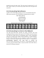
2.3.3 Connecting Serial Device
The EKI-1121L/1122L/1124L provides one, two or four standard serial ports
DB9 (male) connectors. RS-232/422/485 pin assignments are as below.
Table 2.3 EKI-1121L/1122L/1124L Serial Port Pin Assignments
Pin
1
2
3
4
5
6
7
8
9
RS-232
DCD
RX
TX
DTR
GND
DSR
RTS
CTS
RI
RS-422
TX-
-
-
TX+
GND
-
RX+
-
RX-
RS-485
Data-
-
-
Data+
GND
-
-
-
-
2.3.4 Connecting to a Host or the Network
The EKI-1121L/1122L/1124L provides two RJ45 connectors with dual
independent Ethernet networks and supports 10/100 Mbps transmission speed.
The EKI-1121L/1122L/1124L will automatically detect current transmission
speed on the network and configure itself accordingly. For normal operation,
the EKI-1121L/1122L/1124L can be connected to other hubs or switches
through a twisted-pair straight through the Ethernet cable. For configuration or
troubleshooting
purposes,
user
may
need
to
connect
the
EKI-1121L/1122L/1124L directly to the host PC. In this operation mode, user
can use a crossover Ethernet cable to connect the EKI-1121L/1122L/1124L to
the host PC‟s Ethernet connector.
15
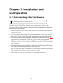
Chapter 3: Installation and
Configuration
3.1 Connecting the Hardware
Use 115200 bps, N81 to connect console.
The EKI-1121L/1122L/1124L offers an easy setup feature. Take out the
EKI-1121L/1122L/1124L and the accessories from the package and follow the
steps below for initial setup:
1. Connect the EKI-1121L/1122L/1124L LAN1 to your network with standard
RJ-45 connector.
2. Use the console cable inside the release package to connect the console
port on EKI-1121L/1122L/1124L with serial port on your develop desktop.
3. Use your familiar console application to open the serial port, such as: Super
HyperTerminal on Windows, minicom on Linux, third party application
Netterm, or kind of. Use baud rate 115200 bps, no parity, 8 bits data length
and 1 stop bit.
4. Connect the power cord to the EKI-1121L/1122L/1124L and plug the other
end of the cord into the power outlet. Then boot the
EKI-1121L/1122L/1124L immediately. The boot up process may need about
9 seconds till the uClinux operation system is ready.
5. After power on, you can see the boot up messages like below.
16
Figure 3.1 The boot up messages
6. When you see the prompt, the system is ready.
Note:
1. Use direct cable rather than cross-over cable; otherwise there is no
message shown to you!
2. If you power on before open minicom, you can not see the boot up
messages like that. But the boot up process may be successful.
3.2 OS Configuration and Usage
Before configure and use, user must release other1.tar.gz files to /var. because
it includes all of configured files.
3.2.1 Configure RTC
Use the data command to modify the date.
Usage: date [OPTION] … [MMDDhhmm[[CC]YY][.ss]][+FORMAT]
For example, Tue Apr 10 15 :39 :12 UTC 2007. You can type in "date
041015392007.12" to update system date.
17
Figure 3.2 Configure RTC
In order to maintain the correct time when power off, user should use the
„hwclock -w‟ to write the current system time to real time clock and use the
„hwclock -s‟ to read the real time clock into system.
Now if you reboot the EKI-1121L/1122L/1124L, the time is still correct.
Because command „hwclock -s‟ in /etc/rc(/var/other1/init.custom) executes by
default.
3.2.2 Configure IP
After connect to the console and power on the device, you can use following
command to enable Ethernet or you can modify the
/etc/rc(/var/other1/init.custom) file to bring up Ethernet when booting up by
default.
3.2.2.1 Using Static IP
User can modify the /etc/rc(/var/other1/init.custom) file like below to make
system boot up using static IP. /etc/rc(/var/other1/init.custom) will be executed
when system boot up if the file exists.
ifconfig eth0 10.0.0.1 broadcast 10.0.0.255 netmask 255.255.255.0
And user can configure IP address with command line. For example:
18
Figure 3.3 Configure Ethernet Interface Using Static IP
3.2.2.2 Using DHCP
User can modify the /etc/rc(/var/other1/init.custom) file like below to make
system boot up using DHCP.
dhcpcd eth0 &
And user can obtain IP address with command line. For example:
Figure 3.4 Configure Ethernet Interface Using DHCP
19
3.2.3 TELNET Service and Client
When boot up the EKI-1121L/1122L/1124L, the telnet service is already started
by default. User can telnet to EKI-1121L/1122L/1124L by telnet client in
another computer. After you telnet into the EKI-1121L/1122L/1124L, all the
other operations is the same as using console. And you can telnet to other
computer by telnet client in EKI-1121L/1122L/1124L as well. Use command like
this:
Figure 3.5 TELNET Service and Client
3.2.4 FTP Service and Client
When boot up the EKI-1121L/1122L/1124L, the ftp service is already started by
default. User can ftp to EKI-1121L/1122L/1124L by ftp client in another
computer to get and put files.
20
Figure 3.6 FTP Client in Another Computer
„172.21.73.100‟ is your EKI-1121L/1122L/1124L‟s IP address. „Name‟ can be
„anonymous‟ or „ftp‟ and „Password‟ can be any or none.
Use command to get and put file like this:
Figure 3.7 FTP Command in Another Computer
Please look at „get‟ and „put‟ command line. In „get‟ command line, user must
use full path of file that will be transmitted from EKI-1121L/1122L/1124L to a
local file with the same name. In „put‟ command line, user must use full path of
file of EKI-1121L/1122L/1124L and the file name must be same as that will be
put.
21
If user wants to connect other computers by ftp client in
EKI-1121L/1122L/1124L, use command to put and get file like this:
Figure 3.8 FTP Client in EKI-1121/1122/1124
„172.21.73.74‟ is another computer‟s IP address.
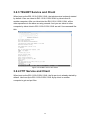
3.2.5 TFTP Service and Client
When boot up the EKI-1121L/1122L/1124L, the tftp service is already started
by default. User can tftp to EKI-1121L/1122L/1124L by tftp client in another
computer. Use command to get and put file like this:
Figure 3.9 TFTP Client in Another Computer
22
„172.21.73.100‟ is your EKI-1121L/1122L/1124L‟s IP address. In „get‟ command
line, user must use full path of file that will be received from
EKI-1121L/1122L/1124L. In „put‟ command line, user must use full path of file
of EKI-1121L/1122L/1124L and file name must be the same as that will be put.
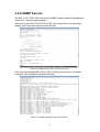
If user wants to connect another computer by tftp client in
EKI-1121L/1122L/1124L, use command to get and put file like this:
Figure 3.10 TFTP in EKI-1121L/1122L/1124L
„172.21.73.65‟ is another computer‟s IP address. User can use “tftp –g –r ….”
to send file to another computer and use “tftp –p –l ….” to get file from another
computer.
3.2.6 NFS Client
User can mount file system to EKI-1121L/1122L/1124L provided by another
computer with NFS service. Use „mount‟ command like this:
23
Figure 3.11 NFS Client in EKI-1121L/1122L/1124L
„172.21.73.74‟ is another computer‟s IP address. „/mnt/aaa‟ is file system
supported by another computer. User can mount it to EKI-1121L/1122L/1124L.
3.2.7 NTP Client
User can synchronize time on EKI-1121L/1122L/1124L by using ntp client. Use
„msntp‟ command like this:
Figure 3.12 NTP Client in EKI-1121L/1122L/1124L
„172.21.73.74‟ is NTP server‟s IP address.
24
3.2.8 SNMP Service
The EKI-1121L/1122L/1124L has built-in SNMP (Simple Network Management
Protocol) v1 and v2c agent software.
When boot up the EKI-1121L/1122L/1124L, the snmp client is not started by
default, user must start snmp serveice like this:
Figure 3.13 SNMP Client in EKI-1121L/1122L/1124L
Then user can manage EKI-1121L/1122L/1124L by snmp service in another
computer, use „snmpwalk‟ command like this:
Figure 3.14 SNMP Message in Manage Computer
25
And user can modify /var/other1/snmpd.conf which is linked to /etc/snmpd.conf
to change configuration.
3.2.9 Mail Client
EKI-1121L/1122L/1124L use smtpclient to send mail which is a minimal SMTP
client that takes an email message body and passes it on to an SMTP server.
When boot up the EKI-1121L/1122L/1124L, the smtp client is already started
by default. User can send mail via smtp server. Use „mail‟ command to send
mail like this:
Figure 3.13 MAIL Client in EKI-1121/1122/1124
„172.21.73.74‟ is smtp server‟s IP address. „AdvantechNew‟ defined in
/etc/resolve.conf is locale host name. „test‟ is sender mail name and „user1‟ is
receiver mail name. After input „mail‟ command line and Press enter key, you
can input context of mail and press CTRL+D to send & exit.
3.2.10 Web Server
The boa is a small web server .If you want the web server starting by default,
user must add „boa:unknown:/bin/boa -c /www &‟ to /etc/inittab. To use web
server, user can use vi to modify /var/other1/www/boa.conf which is released
from other1.tar.gz like this:
Port 80
User 0
Group 0
DocumentRoot /www
26
UserDir public_html
DirectoryIndex index.htm
KeepAliveMax 1000
KeepAliveTimeout 10
DefaultType text/html
AddType application/x-httpd-cgi cgi
ScriptAlias /cgi-bin/
/www/cgi-bin/
AddType image/jpeg jpg
Because the default homepage is already located at
/var/other1/www/index.htm released from other1.tar.gz, user can open default
page. Type “http://‟IP_address‟” („IP_address‟ is web server‟s LAN IP address
which is still active.) in the address box of a browser (such as Microsoft
Internet Explorer or Mozilla Firefox) from your PC. And user can open default
CGI page, type “http://‟IP_address‟/cgi-bin/hello.cgi” in your browser‟s address
box.
If user wants to make your pages. You can do it like this:
Firstly, save your own homepage to the following
directory:/var/other1/www/.And then save your CGI page to the following
directory: /var/other1/www/cgi-bin.
After that, you can browse to EKI-1121/1122/1124 by web browser in another
computer.
3.2.11 PPP Client
Before use it, user must open and modify /var/other1/ppp-on firstly.
#!/bin/sh
DEV=/dev/ttyS3
BAUDRATE=115200
NAME=USERNAME
DIAL_SCRIPT=/var/other1/ppp-on-dialer
pppd lock modem crtscts asyncmap 20A0000 escape FF $DEV $BAUDRATE
noipdefault defaultroute noauth name $NAME connect $DIAL_SCRIPT
Please replace „/dev/ttyS3‟ and „115200‟ with correct serial port and baud rate.
And replace „USERNAME‟ with login account.
Secondly, user must open and modify /var/other1/ppp-on-dialer.
#!/bin/sh
TELEPHONE=NUMBER
HANGUP=ATH0
RESET_MODEM=ATZ
27
INIT_MODEM=ATL1M1V1S11=55S7=75
DIAL=ATDT$TELEPHONE
chat ABORT 'ERROR' ABORT 'BUSY' ABORT 'NO ANSWER' ABORT
'RING\r\n\r\nRING' '' AT 'OK-+++\c-OK' $HANGUP OK $RESET_MODEM OK
$INIT_MODEM TIMEOUT 30 OK $DIAL CONNECT ''
Please replace „NUMBER‟ with the telephone number.
Use the following command to launch the ppp connection.
/>/var/other1/ppp-on &
After the connection is built, a new Ethernet interface ppp will attach to system.
3.2.12 PPPoE client
Before use it, user must open and modify /var/other1/pppoe-on firstly.
#!/bin/sh
USER=USERNAME
pppd debug lock usepeerdns noipdefault noauth defaultroute local name $USER pty
/var/other1/pppoe-dialer
Please replace „USERNAME‟ with correct user name.
Secondly, user must open and modify /var/other1/pppoe-dialer.
#!/bin/sh
ifconfig eth0 up
pppoe -p /var/run/adsl.pid -I eth0 1412
Please replace „eth0‟ with correct interface of Ethernet.
Thirdly, user must open and modify /var/other1/pppoe.conf.
ETH=eth0
USER=USERNAME
DEMAND=no
USEPEERDNS=yes
CONNECT_TIMEOUT=60
CONNECT_POLL=6
PING="."
PIDFILE=/var/run/adsl.pid
SYNCHRONOUS=no
CLAMPMSS=1412
LCP_INTERVAL=20
LCP_FAILURE=3
PPPOE_TIMEOUT=80
FIREWALL=NONE
28
PPPOE_EXTRA=""
Please replace „USERNAME‟ with correct user name and „eth0‟ with correct
interface of Ethernet.
Fourthly, user must open and modify /var/other1/www/chap–secrets.
"USERNAME"
*
"PASSWORD"
*
Please replace „USERNAME‟ with correct user name and „PASSWORD‟ with
correct password.
At last, user must open and modify \var\other1\www\pap-secrets.
"USERNAME"
*
"PASSWORD"
*
Please replace „USERNAME‟ with correct user name and „PASSWORD‟ with
correct password.
Use the following command to launch the pppoe connection.
/>/var/other1/pppoe-on &
After the connection is built, a new Ethernet interface ppp will attach to system.
3.3 Partition of Flash
As mentioned before, the flash has 4 partitions: The first is used by boot loader;
the second is used by uClinux kernel; the third is used by root file system and
the forth is reserved for user use. It is about 2.6 MB, identified as
/dev/mtdblock3 and mounted at /var/other1.
Redboot
0x 0000 0000 ~ 0x 7F06 0000
linux.bin.lzo
0x 7F06 0000 ~ 0x 7F16 0000
romfs.img
0x 7F16 0000 ~ 0x 7F56 0000
user space
0x 7F56 0000 ~ 0x 7F7F 0000
FIS directory
0x 7F7F 0000 ~ 0x 7F7F F000
Redboot config 0x 7F7F F000 ~ 0x 7F80 0000
29
Chapter 4: Development Guide
4.1 Establish Develop Environment
4.1.1 Install the Cross Compile Tool Chain
Install Linux distribution on your host computer.
Use root account to login system.
Put arm-uclinux-tool-20080121-advantech.tar.bz2 under “\” path. You can find
the file at release\toolchain\linux\.
Use “tar jxvf arm-uclinux-tool-20080121-advantech.tar.bz2” to uncompress the
tool chain.
The tool chain has been installed into your system.
4.1.2 Setup the Runtime Environment
1. Use the account who wants to use this tool chain to login.
2. Append /usr/local/arm-uclinux-tool-20080121/bin to environment variant
PATH and export it.
3. Add following line into .bash_profile. (According to the different shell you
use, the configuration file name maybe different.)
export PATH=/usr/local/arm-uclinux-tool-20080121/bin:PATH
4. Re-login the account.
5. Use „whereis arm-elf-gcc‟ or „which arm-elf-gcc‟ command to make sure the
command points to the correct arm-elf tool chain.
6. Use „arm-elf-gcc -v‟ command to make sure you are using the correct
version of arm-elf tool chain.
7. Now the development environment is established.
4.2 Put Applications into
4.2.1 Check the Flash Memory Space
Sometimes, user want execute applications in file system of
EKI-1121L/1122L/1124L,
To build the example application “hello”, use the following process.
1. Copy the files “hello.c” and “Makefile” to your working directory.
30
2. Change to your working directory and issue the command “make” to build the
application. When successfully built, you should see the following. Then
copy hello to /home/aaa .
Figure 4.1 How to make hello
3. To test the application, place the file “hello” on an ftp server. Next, connect
to the EKI-112x via console or telnet, and change to the
“/var/other1“ directory. Use the following commands to ftp the file “hello”
from the ftp server.
4. Change the file permissions as follows.
5. Finally use the following command to execute the program.
Figure 4.2 How to get hello via FTP
31
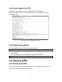
4.2.2 User Space via FTP
Sometimes, user wants to execute applications in file system of
EKI-1121L/1122L/1124L. Please use the following commands to get and
execute the files.
Figure 4.2 How to Get Applications via FTP
4.2.3 Root File-system
1. Uncompress romfs.tar.bz2 to a temporary folder.
tar jxvf romfs.tar.bz2
2. Put your applications to relative directory or modify the configuration files
as you want.
3. Use following command to generate a new root file system.
genromfs -v -V “ROMdisk” -f romfs.img -d romfs
4. Refer to Appendix A to update root file system.
4.3 Device APIs
4.3.1 Serial port APIs
Each serial port has an associated device file. To access a serial port, you
simply open the corresponding device file.
32
Peripheral
Device File
Serial Port 1
/dev/ttyS2
Serial Port 2
/dev/ttyS3
Serial Port 3
/dev/ttyS4
Serial Port 4
/dev/ttyS5
Port configuration is done using the POSIX termios interface. Developing in
C, you will first need to include the <termios.h> header file to use the required
functions.
Additionally, the serial port line drivers are software configurable for RS-232,
RS-422 or RS-485 operation, through the termios interface. You will need to
include the adv.h header file or the following defines.
#define IRS422
0100000
#define IRS485
0200000
Then, use the following instructions to set the termios structure, followed by the
tcsetattr function to set the new configuration.
switch(gMode) {
case MODE_RS232:
PortTermios.c_iflag &= ~IRS422;
PortTermios.c_iflag &= ~IRS485;
break;
case MODE_RS422:
PortTermios.c_iflag |= IRS422;
PortTermios.c_iflag &= ~IRS485;
break;
case MODE_RS485:
PortTermios.c_iflag &= ~IRS422;
PortTermios.c_iflag |= IRS485;
break;
}
//Set the new serial port interface type
tcsetattr(portHandle, TCSANOW, &PortTermios);
For a complete example of serial port configuration, please see the provided
serialecho.c example.
33
4.3.2 RTC APIs
To access a RTC device, you simply open the corresponding device file.
Peripheral
Device File
Real Time Clock
/dev/rtc
4.3.3 LED APIs
To access a LED device, you simply open the corresponding device file.
Peripheral
Device File
LED Indicator
/dev/led
Developing in C, you will first need to include the <stdio.h> <sys/types.h>
<sys/ioctl.h> <unistd.h> and "ledman.h" header file to use the required
functions.
Then, use the following program to set the command, followed by the ioctl
function to control leds.
if(flag)
{
flag = 0;
cmd = LEDMAN_CMD_ON;
/*your action*/
}
else
{
flag = 1;
cmd = LEDMAN_CMD_OFF;
/*your action*/
}
if( ioctl(devfp, cmd, LEDMAN_HEARTBEAT) < 0
|| ioctl(devfp, cmd, LEDMAN_RESET) < 0 )
{
/*your action*/
}
For a complete example of serial port configuration, please see the provided
lmtest.c example.
34
Chapter 5: Troubleshooting
35
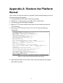
Appendix A: Restore the Platform
Kernel
Just in case if the kernel or flash is corrupted, follow the below steps to recover
the kernel and root file system.
1. Connect the EKI-1121L/1122L/1124L with console.
2. Press Ctrl + C when power on the EKI-1121L/1122L/1124L.
3. You should see the following messages.
4. Start your TFTP server and put the kernel.lzo and romfs.img under the
TFTP directory.
5. Assume your TFTP server‟s IP is 172.21.73.65. Use the following
commands.
Figure A.1 How to Recover Kernel and Root File System
6. After restart the EKI-1121L/1122L/1124L, the kernel and root file system
should be recovered.
36
Appendix B: Erase JFFS2 File
System
1. Sometimes, you may encounter the issue during development. You may
see the output message like below.
mtdblock_open
ok
jffs2_scan_empty(): Empty block at 0x003142e4 ends at 0x00316000 (with
0x00000000)! Marking dirty
JFFS2: Erase block at 0x00310000 is not formatted. It will be erased
Cowardly refusing to erase blocks on filesystem with no valid JFFS2 nodes
mtdblock_release
ok
mount: wrong fs type, bad option, bad superblock on /dev/mtdblock3,
missing codepage or other error
mtdblock_open
ok
mtdblock_release
ok
In some cases useful info is found in syslog - try
dmesg | tail or so
pid 14: failed 8192
2. Try to use following command to solve this issue.
Sash command shell (version 1.1.1)
/> umount /var/other1
/> eraseall /dev/mtd3
MTD_open
MTD_ioctl
Erasing 64 Kibyte @ 0 -- 0 % complete.MTD_ioctl
Erasing 64 Kibyte @ 10000 -- 1 % complete.MTD_ioctl
Erasing 64 Kibyte @ 20000 -- 3 % complete.MTD_ioctl
......
Erasing 64 Kibyte @ 3c0000 -- 95 % complete.MTD_ioctl
Erasing 64 Kibyte @ 3d0000 -- 96 % complete.MTD_ioctl
Erasing 64 Kibyte @ 3e0000 -- 98 % complete.MTD_ioctl
Erased 4032 Kibyte @ 0 -- 100% complete.
MTD_close
/>reboot
3. Restart the device.
37
Appendix C: Command
Collection
File manager
1.mount:
Mount a filesystem. You need this to access NFS and SMB filesystems.
2.umount:
Unmount a filesystem.
3.ar:
Extract or list files from an ar archive.
4.basename:
Strips directory path and suffixes from FILE. If specified, also removes
any trailing SUFFIX.
5.cp:
Copy files.
6.dd:
Copy a file with formatting and conversions.
7.df:
Print the filesystem space used and space available.
8.dirname:
Strips non-directory suffix from arguments.
9.du:
Summarizes disk space used for each file argument and/or directory. Disk
space is printed in units of 1024 bytes
10.gunzip:
Uncompress files.
11.gzip:
Compress files.
12.ln:
Create a link between two files.
13.ls:
List directory contents.
14.mkdir:
Create directory(ies), if they do not already exist.
15.mkfifo:
Creates a named pipe.
16.knod:
Create a special file (block, character, or pipe).
17.mv:
Move (rename) files.
18.pwd:
Print the full filename of the current working directory.
19.rm:
Remove (unlink) the file(s). You may use '--' to indicate that all following
arguments are non-options.
20.rmdir:
Remove the directory(ies), if they are empty.
21.sync:
Write all buffered filesystem blocks to disk.
Editor
22.cat:
23.cmp:
24.cut:
25.echo:
26.find:
27.grep:
Concatenates FILE(s) and prints them to stdout.
Compare files.
Prints selected fields from input file to standard out.
Prints arguments to stdout.
Search for files in a directory hierarchy.
Search for a pattern in each file or standard input.enable context :
38
Support for the EGREP applet (alias to the grep applet). Alias egrep to
grep -e : Support for the EGREP applet (alias to the grep applet)
28.more:
More is a filter for viewing a file one screenful at a time.
29.sed:
Stream editor.
30.sort:
31.tail:
Sorts lines of text in the specified files.
Print last 10 lines of each file to standard output. With more than one file,
precede each with a header giving the file name. With no file, or when file
is -, read standard input.
32.tee:
Copy standard input to each file, and also to standard output.
33.test:
Checks file types and compares values returning an exit code determined
by the value of an expression.
34.top :
35.touch:
36.tr:
Update the last-modified date on the given file[s].
Translate, squeeze, and/or delete characters from standard input,writing to
standard output.
37.vi:
Visual file editor.
Network
38.boa:
39.dhcpcd:
The DHCP client daemon, used to get an IP address from a DHCP
server.
40.ftp:
An ftp client
41.ftpd:
42.inetd:
43.mail:
Client which allows mail to be sent to other hosts that support SMTP
44.msntp:
Simple Network Time Protocol utility.
45.portmap:
The portmapper service, needed for NFS under 2.4.
46.pppd:
Dialup networking daemon.
47.pptpd:
PPTP VPN daemon.
48.pptp:
PPTP Client for establishing VPN's.
49.rp_pppoe:
The Roaring Penguin PPPOE.
50.telnetd:
Allow remote users to login to the system using telnet.
51.telnet:
A telnet client application.
52.tftpd:
A tftp server
53.chat:
The chat command is used for PPP and other processes that need to talk
to modems.
54.hostname:
55.ifconfig:
Get or set the hostname or DNS domain name.
Configure a network interface.
39
56.iproute:
Equivalent to selecting route support to "ip", above.
57.netstat:
netstat prints information about the Linux networking subsystem.
58.nslookup:
Queries the nameserver for the IP address of the given host.
59.ping:
Send ICMP ECHO_REQUEST packets to network hosts.
60.route:
Edit the kernel's routing tables.
61.tftp:
Transfers a file from/to a tftp server using "octet" mode.
put: Support the TFTP PUT command.
get: Support the TFTP GET command.
62.traceroute :Print the route packets take to a network host.
63.wget:
Retrieves files via HTTP or FTP.
Process
64.kill:
65.killall :
66.ps:
Send a signal to the specified process(es).
Send a signal to the specified process(es)
Report process status. This version of ps accepts no options.
Others
67.cpu:
cpu tool
68.setserial: User level serial port configuration tool.
69.clear:
Clear screen.
70.date:
Displays the current time or sets the system date.
71.dmesg:
72.hwclock:
Prints or controls the kernel ring buffer.
The hwclock utility is used to read and set the hardware clock on a
system. This is primarily used to set the current time on shutdown in
the hardware clock, so the hardware will keep the correct time when
Linux is _not_ running.
73.mesg:
Mesg controls access to your terminal by others. It is typically used to
allow or disallow other users to write to your terminal
74.reboot:
Reboot the system.
75.sleep :
Pause for a specified number of seconds.
76.time:
77.TTY:
Print the file name of the terminal connected to standard input.
78.uname:
Print certain system information.
79.uptime:
Display the time since the last boot.
80.usleep:
Pause for N microseconds.
81.yes:
Repeatedly outputs a line with all specified string(s), or 'y'.
40