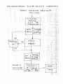
1
US 20020153370A1
(19) United States
(12) Patent Application Publication (10) Pub. N0.: US 2002/0153370 A1
(43) Pub. Date:
Stutman
(54) MOBILE MICROWAVE OVEN
(52)
Oct. 24, 2002
US. Cl. .......................................... .. 219/715; 219/756
(76) Inventor: Peter S. Stutman, Sudbury, MA (US)
(57)
Correspondence Address:
Peter S. Stutman
27 Lillian Avenue
A mobile, loW poWered microwave oven is disclosed. The
oven has top entry to the heating chamber, it is poWered
Sudbury, MA 01776 (US)
(21) Appl. No.:
09/751,893
(22)
Dec‘ 29’ 2000
Flled:
from the cigarette lighter, has the controls and display and
the cooling vents also on the top surface of the oven. The
oven is arranged to be secured to the seat by the seat belts
in such a manner that the oven Will operate While so secured.
Publication Classi?cation
(51)
There is also a spill container in the heating chamber.
Materials may be used that make the oven cabinet transpar
Int. Cl.7 ..................................................... .. H05B 6/80
410
80
200
ABSTRACT
ent.
/
/
‘j
2%’
/
\
4 00
Patent Application Publication
Oct. 24, 2002 Sheet 1 0f 10
US 2002/0153370 A1
4:2.
at
QQN
Patent Application Publication
Oct. 24, 2002 Sheet 2 0f 10
3
n u E)
2
1
M zS
4
5
6MODE
US 2002/0153370 A1
STOP
START
1AFig.
Patent Application Publication
Oct. 24, 2002 Sheet 3 0f 10
US 2002/0153370 A1
Patent Application Publication
Oct. 24, 2002 Sheet 4 0f 10
160
Fig- 3
US 2002/0153370 A1
Patent Application Publication
Oct. 24, 2002 Sheet 5 0f 10
zom?é
.E
US 2002/0153370 A1
f\
2m5&5
>1$261
mm
\‘
\
V
m
®
6
<
0
5
>
/
z
m
o
w
c
i
n
o
w
m
3mm
am»_ 2.
\
M
omomm.U
QEHQQ21#061@9$I‘l,.
3%
2
>
%
M20.
<
i
w
5
PW.Q
wm2w58m9m6
mm
.m
.mw__EjozIG!L
.3
r
.mt
w
Patent Application Publication
L0
2:
\
Oct. 24, 2002 Sheet 6 0f 10
US 2002/0153370 A1
120 \
121
Fig.
5
Patent Application Publication
Oct. 24, 2002 Sheet 7 0f 10
US 2002/0153370 A1
Fig.
,9; 5A
Patent Application Publication
Oct. 24, 2002 Sheet 8 0f 10
93
190
\
190
I
Fig.
6
US 2002/0153370 A1
Patent Application Publication
Oct. 24, 2002 Sheet 9 0f 10
‘f MOEWE ‘HICVQOWKAYJET 5 bit/‘55M’; '
1 I 6 P5 RAT (m! Pd, 111L059
if
, jaw/W1“
p 75235-10209 _1
US 2002/0153370 A1
Oct. 24, 2002
US 2002/0153370 A1
MOBILE MICROWAVE OVEN
transparent microWave cavity liner designed to contain
spilled foods and facilitate cleaning. Methods of retaining
RELATED APPLICATIONS
food containers Which hold the foods being heated, as Well
as other safety and convenience features useful for real
World operation in the mobile environment are described.
[0001] The present application claims priority from US.
Provisional Patent Application, entitled Mobile MicroWave
Oven, Ser. No. 60/173,679, Which application Was ?led on
Dec. 29, 1999, by Peter S. Stutman, a US. citiZen, of 27
Lillian Avenue, Sudbury, Mass., 01776 and Which provi
sional is hereby incorporated herein by reference.
FIELD OF THE INVENTION
[0002]
This invention generally relates to microWave
[0006] It is envisioned that the device described Will ?nd
Wide application in cars, trucks, recreational vehicles, boats
and simple living situations Which do not provide conven
tional AC mains and in Which consumers are unlikely to
perform or have performed involved installations. It can be
used for many tasks, from heating baby bottles and meals in
properly designed containers, to heating the morning’s cof
ovens and more speci?cally to microWave ovens for use in
fee, to Warming automotive gasket materials in cold climates
vehicles such as cars, trucks, and boats. It has features
speci?c to operation from a standard DC poWer source
found in such vehicles as Well as features Which mechani
cally secure it Within the vehicle.
during repair operations.
[0007] In the preferred embodiment, a high frequency
sWitching poWer supply generates the required ?lament and
high voltage necessary for magnetron operation. This is
BACKGROUND OF THE INVENTION
more ef?cient than suffering DC/AC inverter losses in
[0003] MicroWave ovens designed for portable operation
and operation in vehicles have been proposed previously.
poWer transformer. The magnetron is the type Whose mag
US. Pat. No. 4,667,075 of Sakurai proposes using a three
phase AC alternator to supply poWer. US. Pat. No. 5,276,
300 of LoW et al, describes a microWave oven containing
essentially an inverter to alloW 12 volt DC operation. AGOR
technologies of Verson, France manufactures a similar prod
uct. These devices, operated at poWer levels of about 0.6-1.0
kW nominal require DC input currents from a 12 volt source
of approximately 100 amperes. This much current requires
direct connection to the vehicle battery With very heavy
gauge Wire or the dedicated alternator of Sakai and implies
mechanical and electrical installation skills beyond the range
of the average consumer. The oven must also be somehoW
mounted to the vehicle so that it does not move around. The
microWave ovens previously described are mechanically
very similar. They feature a cavity With a front opening door;
that is, With a vertical hinge. The timer and control keypad
is mounted vertically in proximity to the door and they are
very similar to or modi?cations of conventional consumer
microWave ovens.
[0004]
Conventional consumer microWave ovens have
poWer ratings in the 500W-1000W range. These ratings
represent the poWer delivered into the oven cavity. The
nameplate poWer consumption of these microWave ovens is
addition to the losses seen in the typical microWave oven
netic ?eld is generated by permanent magnets.
[0008] The only readily available electrical outlet or jack
in most modem cars and trucks and smaller boats is the
familiar “cigarette lighter” or “accessory poWer” socket.
This socket is familiar to millions of users Who poWer
mobile phones, radar detectors, small inverters and other
convenience devices from them. These jacks are typically
fused at 15-30 amperes. This limits total electrical poWer
input to the microWave oven described here to a range of
approximately 200-400 Watts. This corresponds to a typical
microWave poWer rating of about 125-250 Watts. Most users
of microWave ovens are used to larger poWer inputs as
mentioned previously. Therefore the cooking time in this
loW poWer microWave oven Will be longer than the “stan
dard” times experienced in larger, more poWerful units. For
example, if it takes 1 minute to heat a cup of soup to serving
temperature in a 750 Watt microWave oven found in a typical
American kitchen, it Will take three minutes nominally in a
250 Watt unit. In fact, given the signi?cant increase in
cooking times, there Will be thermal losses including radia
tional and convective losses Which Will tend to cool the food
typically 50-75% higher. For example a Magic Chef
being heated and Which Will lengthen the required time
MC-03JS Compact MicroWave oven is rated at 500 Watts
and is rated at a poWer consumption of 750 Watts. While
these ovens could be poWered by a DC to AC inverter of
beyond the simple ratio of poWer. In one mode the invention
described here takes the “standard” cooking time for a
750-900 Watt microWave oven and automatically multiplies
it by an appropriate factor to arrive at the correct heating
appropriate output, the inverter Would have to be hardWired
With heavy gauge Wire, such as No. 0, to the vehicle battery
or alternator in order to receive the necessary current. If We
assume a 90% inverter ef?ciency the 500 Watts oven men
tioned above Would cause a typical inverter to draW a current
of about 60 amperes at a nominal 13.8 volts.
SUMMARY OF THE INVENTION
[0005] This invention is a small, loW-poWer, approxi
mately 200 Watt magnetron-type microWave oven. The
invention described herein is designed to be poWered by a
time for this loWer-poWer oven. In another mode the user
enters a desired heating interval Which is not multiplied by
any factor.
[0009] The invention described herein also senses input
current and voltage. It shuts doWn if excessive current is
draWn to protect the “accessory socket’ fuse or if voltage
drops to a level just above that Which corresponds to the
vehicle battery being unable to start the vehicle.
to be held in place on a seat by a standard vehicle seat-belt.
[0010] A microWave oven, even a small one, is a substan
tial mass, and it may contain foods Which are near or at the
Also described is an upWard-opening door and plastic radio
boiling point. It must be securely mounted Within the vehicle
vehicle’s “accessory poWer” or “cigarette lighter” jack and
Oct. 24, 2002
US 2002/0153370 A1
cockpit, such that in case of an emergency maneuver, sudden
acceleration, or crash, it does not ?y about the cockpit
seat of long vehicles While being plugged into the “cigarette
lighter” or “accessory socket” Which is usually proXimal to
causing injury or burn hazards to passengers nor damaging
other components of the vehicle. The present invention has
split loops affixed to the outside of the cabinet Which
the vehicle’s front seat.
facilitate securing the microWave oven in a seat With the
seatbelt much as a child’s safety seat Would. In the event of
a collision the microWave oven described here shuts doWn.
[0016]
[0017]
FIG. 1A: Keypad for Mobile MicroWave Oven
It also has the usual safety features such as door interlocks
and over-temperature sensors found in virtually all con
[0018]
FIG. 2: Mobile MicroWave Oven Interior
[0019]
FIG. 3: Mobile MicroWave Oven Door, Door
sumer microWave ovens. Conventional mounting points are
Locking Solenoid, and Interlock
provided for situations in Which the device may be bolted
doWn.
[0020] FIG. 4: Mobile MicroWave Oven System Diagram
[0011] The invention described herein also places the
intake and exhaust for the cooling air required by the
magnetron on the top surface such that the airflow is not
BRIEF DESCRIPTION OF THE DRAWINGS
[0021]
FIG. 1: Mobile MicroWave Oven
FIG. 5: Inverted Pyramidal Food Retainer and
Cavity Liner
[0022]
FIG. 5A: Food Container Retention Stud
FIG. 6: VieW of Mobile MicroWave Oven in Seat
impeded as it Would be if mounted on a seat With doWnWard
[0023]
or side facing intakes and exhausts. The keypad is also
Retained by Seatbelt
mounted on the top surface for easy access.
[0024] FIG. 7: Side VieW of Mobile MicroWave Oven in
Seat Retained by Seatbelt
[0012] The invention described herein also has an upWard
opening door alloWing access to the oven cavity. The cavity
[0025] FIG. 8: Mobile MicroWave Oven Operational
has a radio-transparent, removable, easily cleaned, plastic
FloWchart
liner made of heat resistant plastic Which contains any spills
Which may occur. These tWo features help insure that even
if food somehoW should spill Within the oven, that it Will not
leak out into the vehicle cabin. The door is retained shut by
a locking mechanism When the oven is in operation and may
stay in that state until an unlock button is pushed on the
unit’s keypad.
[0013] Since the vehicle may be in motion While the
invention is in use, means must be provided of ?xing the
food container in place so that it does not “bounce around”
and spill its contents nor damage the cavity Walls. In the
preferred embodiment, a detented stud is centrally affixed to
the center of the carousel. There are mating cavities molded
into “microWave safe” plastic heating containers With lock
ing lids and appropriate vents. The food is placed into the
container, the vented lid is affixed With a latching lip or
similar arrangement, and the cavity, typically in the center of
the container is pressed doWn onto the detented stud Which
retains it in place. Food portions in disposable heating
containers, such as “Chef Boyardee® Lasagna, MicroWave
Meals, (10.5 OZ. siZe)” can be manufactured With the appro
priate mating cavity molded in.
[0014] Alternatively an inverted pyramidal Well is molded
into a radio-transparent, heat resistant plastic support sheet.
Food in appropriate containers is placed doWn into the Well
until contact is made With the Walls of the Well. Alternatively
a curved non-metallic spring-loaded radio-transparent Wall
could be used as retention device.
[0015] A carrying handle is molded into the top surface to
facilitate handling of the mobile microWave oven. A DC
DETAILED DESCRIPTION OF DRAWINGS
DESCRIPTION OF SYSTEM
[0026]
The LOW-POWER MOBILE MICROWAVE
OVEN is typically placed on a passenger seat. On its top
surface are the CONTROL KEYPAD AND DISPLAY (60),
the magnetron COOLING AIR INTAKE (80) and OUTLET
(110), and the upWard opening microWave CAVITY DOOR
(160) af?Xed by HINGE (150). The HINGE (150) can be
positioned on any of the four sides of the MICROWAVE
CAVITY (120) opening in The door seals the cavity so as to
contain all microWave energy by means of conductive
elastomeric GASKET (210) and conventional choke seal
design.
[0027] The mobile microWave oven CABINET (200) is
secured in place on the seat by running the seatbelt for that
seat through the SPLIT LOOPS (190) attached to the CABI
NET (200). The Waist portion of the seatbelt is tightened to
secure the CABINET (200) in place. The SPLIT LOOPS
(190) are angled doWn from the vertical plane toWard the
seatback so as to facilitate force components acting on the
CABINET (200) doWn toWard the seat cushion and back
Ward toWard the seatback Without kinking or narroWing of
the belt Where it passes through the SPLIT LOOPS (190).
This method is similar to that used to secure infant and child
safety seats in vehicles. Alternatively, angle brackets and
screWs suitably attached to the CABINET (200) can be used
to effect a permanent mounting.
[0028] The “cigarette lighter” or “accessory poWer
socket” PLUG (10) is inserted into the vehicle’s “CIGA
RETTE LIGHTER” or “ACCESSORY” socket. A tWo
conductor insulated POWER CABLE (15) of at least #8
gauge attached in series With the plug (10) brings poWer into
the microWave oven’s cabinet (200). This positive lead of
input cable terminated in a “cigarette lighter” plug or other
suitable connector of sufficient length and sufficient gauge is
this nominal 12 VDC poWer passes through the current
provided so that the invention may be installed in the back
sensing shunt (20) and is then bussed to the voltage regulator
Oct. 24, 2002
US 2002/0153370 A1
(30), the input of the switching power supply (40), and the
input of the Input voltage sensor comprised of A/D converter
and the OVER TEMPERATURE SENSOR (175) and KEY
STROKE DATA generated by CONTROL KEYPAD AND
(70). It is also connected to the DC fan motor control sWitch
DISPLAY (60).
(95) and the door locking solenoid sWitch (185), and the
[0033] Since this is a relatively loW-poWer microWave
oven, heating times are longer than those of conventional,
oven cavity lamp sWitch (125). The 12 VDC rating in a
vehicle is nominal and is usually closer to 14 VDC When the
vehicle engine is above idle speed
[0029] The voltage regulator (30) is a simple series pass
regulator Which outputs +5 VDC at suf?cient current to
operate the system controller (50), the keypad/display (60)
and associated components. Its devices have voltage ratings
Which are suitable for use in the automotive electrical
environment and Will survive the transients knoWn to eXist
in this environment.
[0030] The sWitching poWer supply (40) is an inverter type
more poWerful microWave ovens typically found in kitch
ens. The invention described here has poWer input to the
cavity of approximately one fourth of the poWer found in
typical kitchen microWave ovens. Most people Who use a
microWave oven are familiar With “standard” heating times.
These familiar times must be multiplied by a factor of
approximately four in order to be correct for the loWer poWer
level in this invention. If a “standard” heating time is entered
via the CONTROL KEYPAD AND DISPLAY (60), the
SYSTEM CONTROLLER (50) multiplies the time by four
in order to Warm the food to the proper temperature. Since
sWitching poWer supply With a 12 VDC nominal input. It
outputs the magnetron ?lament poWer, typically about 3
longer intervals alloW more cooling by radiation and con
vection, a manufacturer might adjust the time further With a
lookup table or algorithm based on empirical results. A
VDC at several amperes as Well as the B- voltage, typically
about 2-4 kV and in this application about 75-100 mA at 2
surface pyrometer or other temperature sensor could also
kV. The eXact voltages depend on the speci?c characteristics
of the magnetron (100). The magnetron anode is typically
grounded to the microWave oven case (200) and the cathode
to anode potential necessary for operation is developed by
depressing the isolated or “?oating” cathode ?lament beloW
ground potential With the negative voltage. The magnetic
?eld of the magnetron is generated by permanent magnets
integral With its housing. While magnetrons operating at the
signal that desired temperature has been reached.
[0034] The CONTROL KEYPAD AND DISPLAY (60)
generates unique digital signals in a format suitable for input
to the SYSTEM CONTROLLER (50), Whenever a key is
pressed. This subsystem also contains display drivers Which
cause symbols and digits to appear in the multi-segment
multi-character alphanumeric display When appropriate data
is received from the SYSTEM CONTROLLER (50).
typical 2450 MHZ frequency have been used in a prototype
DESCRIPTION OF OPERATION
of this invention, other frequencies might be employed to
optimiZe energy transfer into or energy modes in the micro
[0035]
Wave oven cavity. The sWitching poWer supply (40) utiliZes
inductive transformers Whose Wire Windings, insulation and
other mechanical construction produce satisfactory insula
seat in a vehicle. The Waist belt portion of the seatbelt
tion and isolation so that the magnetron (100) ?lament can
The LoW-poWer microWave Oven is placed in a
corresponding to that seat is passed through the SPLIT
LOOPS (190). The Waist belt is tightened doWn to secure the
CABINET (200) in the seat.
be safely ?oated, and so that the high voltage output is not
compromised. The 3 VAC output is electrically ?oating and
connected With Wires With insulation of adequate voltage
lighter” or “accessory poWer” socket of the vehicle in order
rating.
(30) regulates the 12 VDC input to +5 VDC required by the
[0031] The sWitching poWer supply operates at a fre
quency much higher than that of a typical AC line (60 HZ)
and therefore requires less energy storage on the output.
Consequently the poWer supply output can be keyed on and
off very rapidly by means of the PS (PoWer Supply)
ENABLE SIGNAL from the System Controller (50). In the
preferred embodiment, the PoWer supply is driven by a PS
(PoWer Supply) CLOCK generated in ?rmWare by the
SYSTEM CONTROLLER (50), alternatively a separate
clock signal generator could be used.
[0032]
The SYSTEM CONTROLLER (50) is a micropro
cessor With associated RAM and ROM adequate for opera
tion. PoWer is taken from VOLTAGE REGULATOR (30)
Which also serves to isolate and decouple the SYSTEM
CONTROLLER (50) and related components from tran
sients that occur in vehicle poWer systems. Inputs to the
SYSTEM CONTROLLER (50) are Input Voltage Reading;
Vr output by A/D CONVERTER (70), Input Current Read
ing, Ir, developed by CURRENT SHUNT (20) and A/D
CONVERTER (75), the ACCELEROM signal output by
ACCELEROMETER (300), LOGIC CLOCK output by
CLOCK GENERATOR (350), INTERLOCK SIGNALS
from the DOOR CLOSED INTERLOCK SWITCH (180)
[0036] The PLUG (10) is inserted into the “cigarette
to obtain 12 VDC poWer. The VOLTAGE REGULATOR
SYSTEM CONTROLLER (50) and the CLOCK GENERA
TOR (350).
[0037] The DOOR (160) of the MICROWAVE CAVITY
(120) sWings open on HINGE (150). The user places the
food or other substance to be heated in a “microWave safe”,
radio-transparent heating container With a locking vented
lid. If the heating container has a mating recess molded into
the bottom, the container can be “popped” onto the
DETENTED RETAINER STUD (140). If there is no retain
ing component on the heating container the PLASTIC
LINER WITH INVERTED PYRAMIDAL WELL (145), is
used. This component (145) made of radio-transparent,
heat-resistant plastic, is simply placed in the microWave
oven CAVITY (120) in place of the PLASTIC LINER (130).
The food container described above is placed as far doWn
into the Well as it Will go, thus retaining it in most situations.
The DOOR (160) is closed, the SPRING LAT CHING PIN
(175) is captured by the retaining RETAINING SPRING
CATCH (170) and pressing on DOOR INTERLOCK
SWITCH (180) Which closes, sending a logic level signal to
the SYSTEM CONTROLLER (50).
[0038]
The user enters the length of time the food is to be
heated. If the user presses “STANDARD” on the “CON
Oct. 24, 2002
US 2002/0153370 A1
TROL KEYPAD AND DISPLAY(60)”, the SYSTEM CON
other stationary CAVITY (120) Walls, enabling a conven
TROLLER (50) multiplies by a factor Which compensates
tional “front-opening” microWave oven With a vertical
for the loW-poWer feature of this microwave oven. Typically
HINGE (150).
this factor Will be in the range of 2-6. If the user does not
press the “STANDARD” key, the time entered not multi
plied and represents the eXact heating time.
What is claimed is:
[0039] The user presses the “START” key on the CON
TROL KEYPAD AND DISPLAY (60). The SYSTEM CON
1. A loW-poWer microWave oven capable of operating
from the DC poWer normally available in passenger vehicles
TROLLER (50) looks at all input signals after receiving the
“START” signal. The folloWing signals must be present:
[0040]
INTERLOCKS:
DOOR
INTERLOCK
SWITCH (180) actuated by closure of cavity DOOR
(160) in series With OVER TEMPERATURE SEN
SOR (175) Pulls “INTERLOCKS” line to ground.
[0041] Vr: Voltage reading from A/D CONVERTER
(70) must be above minimum Acceptable battery
voltage, nominally 11.5 volts.
[0042] Ir: Current reading from A/D CONVERTER
(75) must be beloW maXimum current rating of
poWer socket in vehicle. Set by manufacturer as a
function of intended usage, nominally 15 amperes in
a small car, as high as 30 amperes in some larger
trucks.
and boats through the “cigarette lighter” or “accessory
poWer” socket and having means of using a seatbelt to
secure the microWave oven in a seat of a vehicle, compris
ing;
A compact microWave oven cabinet enclosing a cavity or
heating chamber, Whose Walls are constructed of a
radio re?ecting material such as metal sheet, having a
similarly constructed door alloWing access to the cav
ity, a source of microWave energy, a magnetron, suit
able for operation at the poWer levels described, receiv
ing poWer at appropriate voltages from a sWitching
poWer supply deriving its poWer from the vehicle
“cigarette lighter” or “accessory poWer” socket.
2. Means for the microWave oven described in claim 1
With its control keypad and display, and cavity door, on the
same top surface such that they may be easily accessed While
the microWave is secured in a seat of a vehicle and so that
[0043]
If not all conditions are satis?ed, a “BEEP” com
mand is sent to the pieZoelectric annunciator to inform the
user. If all conditions are satis?ed the SYSTEM CON
TROLLER (50) begins the heating of the food in its heating
container. This is commanded by outputting the folloWing
signals and causing the folloWing actions:
[0044] PS ENABLE: This signal enables SWITCH
ING POWER SUPPLY (40) operation.
[0045] PS CLOCK: This signal drives the poWer
sWitching circuits in the SWITCHING POWER
SUPPLY (40) thus supplying ?lament voltage 3 VAC
as Well as negative high voltage B- to the cathode
food may be easily placed into, and removed from, the
microWave oven cavity. Cooling air intake and outlet on the
same top surface so they are not blocked, occluded, ,nor
air?oW through them impeded, by proximity to the seat
components or other structures.
3. The microWave oven described in claim 2 With a DC
motor having af?Xed to its shaft a set of fan blades and
positioned so as to intake air from a top surface mounted
vent and plenum, propel the air through the magnetron
anode cooling structure and then through an additional
plenum out another top surface mounted vent.
4. The microWave oven described in claim 3 With a
MAG FAN ON: This signal drives the sWitch
voltage regulator alWays on When the device is connected to
the vehicle poWer source, providing poWer at appropriate
voltage for the various logic and control circuits.
transistor (92) Which causes the DC FAN MOTOR to
turn the attached FAN BLADES (85). This draWs air
solenoid operated locking mechanism to prevent the cavity
(?lament).
[0046]
5. The microWave oven described in claim 4 With a
in through top-mounted cooling air intake and cir
culates it through the attached PLENUM (82) past
the DC FAN MOTOR (90) through the MAGNE
door from springing open While the vehicle is in motion and
thus releasing microWave energy into the vehicle.
TRON ANODE THERMAL RADIATOR (105) and
detented stud, of retaining molded “microWave safe” food
containers With locking lids and appropriate vents in place
eXhausts it via PLENUM (112) through top-mounted
COOLING AIR OUTLET (110).
[0047]
LOCKDOOR: This signal actuates the DOOR
LOCK SOLENOID (390) by driving the sWitch
transistor (395).
[0048] After the inputted time interval has elapsed the
SYSTEM CONTROLLER (50) ceases outputting all the
signals necessary for the heating to occur and the DOOR
(160) is unlocked. If any of the signals required by the
SYSTEM CONTROLLER (50) are lost, (50) ceases output
ting the signals required for heating to occur.
[0049] The preferred embodiment described demonstrates
the advantages of the invention. Variations on the embodi
ment described can be made to accommodate different
installation con?gurations. For eXample, the DETENTED
RETAINER STUD (140) could be moved to one of the four
6. The microWave oven in claim 5 With a means, a
While a vehicle is in motion by means of a mating cavity or
other retaining structure molded in to the bottom of the food
container.
7. The microWave oven in claim 6 With a removable
molded, radio-transparent, heat-resistant, dishWasher-safe
plastic liner constructed to ?t closely into the microWave
oven cavity and covering the bottom eXcept for a clearance
hole for the detented stud and extending most of the Way up
the sides of the cavity, but open at the top.
8. The microWave oven in claim 7 With a different
removable molded, radio-transparent, heat-resistant, dish
Washer-safe plastic liner constructed to ?t closely into the
microWave oven cavity and having an inverted pyramidal
Well into Which food heating containers may be placed so as
to be constrained from movement While the vehicle is in
motion.
Oct. 24, 2002
US 2002/0153370 A1
9. The microwave oven in claim 8 With a digital system
controller consisting of a microprocessor, adequate RAM
and ROM and input buffers and output drivers Which moni
tors acceleration signals from an accelerometer or similar
spatial displacement measuring devices as Well as cavity
door and over temperature interlocks and other sensors
related to safety concerns, and Which causes immediate
system shutdoWn in the event of a haZardous or fault
condition.
10. The microWave oven in claim 9 With an algorithm to
multiply a “standard” heating time for a typical full-siZe
16. A loW-poWer mobile microWave oven for use in a
vehicle or boat comprising;
a cabinet enclosing a cavity or heating chamber, Whose
Walls are constructed of radio re?ecting material such
as metal sheet, and Wherein the cabinet contains a door
that provides access to the heating chamber, controls
for the oven,
a control keypad and display, and air inlet and outlets, a
magnetron for providing microWave energy to the
heating chamber or cavity,
kitchen microWave, and input to the system controller input
via the control keypad, by a factor properly compensating
for the loWer poWer output and consequent longer heating
a sWitching poWer supply that supplies energy to the
time required in this loWer-poWer microWave oven.
a plug and cable from the “cigarette lighter” or “accessory
poWer” socket or similar connector for supplying
poWer to the sWitching poWer supply.
11. The microWave oven in claim 10 With a DC motor
magnetron,
driving a cooling fan for a magnetron supplied With poWer
directly from the vehicle via a transistor sWitch and Whose
intake and eXhaust air?oW is contained Within plenums
17. A loW-poWer mobile microWave oven for use in a
vehicle such as a car, a boat, or an aircraft, Wherein the
vented to the outside of the cabinet.
vehicle contains seat belts, comprising;
12. The microWave oven in claim 11 With a means of
a cabinet enclosing a cavity or heating chamber, Whose
monitoring input voltage and input current to the system and
Walls are constructed of a ’radio re?ecting material
such as metal sheet, and Wherein the cabinet contains a
causing system shutdoWn in the event that the vehicle
battery voltage drops beloW an acceptable level or if the
current being draWn rises near a level Which Will cause the
vehicle poWer outlet fuse to bloW or Which is otherWise
unacceptable.
13. The microWave oven in claim 12 With a carrying
handle molded into the top surface or externally a?iXed
thereto so as to not interfere With any other required func
tions.
14. The microWave oven in claim 13 With an eXternal
cabinet or housing constructed of a transparent or translu
cent material Which alloWs vieWing of the internal compo
nents and construction.
15. A loW-poWer mobile microWave oven for use in a
vehicle or boat comprising;
a cabinet enclosing a cavity or heating chamber, Whose
Walls are constructed of a radio re?ecting material such
as metal sheet,
a magnetron for providing microWave energy to the
heating chamber,
a sWitching poWer supply that supplies energy to the
magnetron,
means for supplying poWer to the sWitching poWer supply,
and
Wherein the cabinet de?nes a top surface,
Wherein the controls for the oven, a control keypad and
display, the cooling air inlets and outlets and a door that
provides access to the heating chamber or cavity are all
provided on the top surface.
door that provides access to the heating chamber,
controls for the oven,
a keypad and display, and air inlets and outlets,
a magnetron for providing microWave energy to the
heating chamber,
a sWitching poWer supply that supplies energy to the
magnetron,
means for supplying poWer to the sWitching poWer supply,
and
means for securing the oven to a seat by the seat belts.
18. A loW-poWer mobile microWave oven for use in a
vehicle or boat comprising;
a cabinet enclosing a cavity or heating chamber, Whose
Walls are constructed of radio re?ecting material such
as metal sheet, and Wherein the cabinet contains a door
that provides access to the heating chamber, controls
for the oven,
a control keypad and display, and air inlets and outlets,
a magnetron for providing microWave energy to the
heating chamber or cavity,
a sWitching poWer supply that supplies energy to the
magnetron, and
means for supplying poWer to the sWitching poWer supply
Wherein the total poWer consumption is less than 300
Watts.