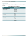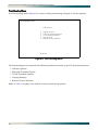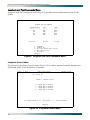
1
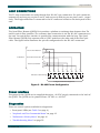
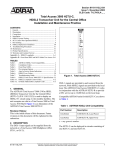
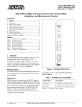
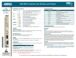
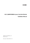
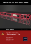
TEST TERM(R MON(G) ) LBK NEND(Y) FENG(G ) DS1 4 FRL7 Q11D81307 OPTIC S DS1 1 DS1 2 DS1 3 K LB CT LE SE CH ® Quad Fiber Remote (QDFR) Unit Installation and Maintenance Practice Document Number: 61181307L7-5E CLEI: M3M1100B _ _ July 2006 Quad Fiber Remote (QDFR) Unit Installation and Maintenance Practice Trademarks Front Matter Any brand names and product names included in this document are trademarks, registered trademarks, or trade names of their respective holders. To the Holder of the Document The contents of this document are current as of the date of publication. ADTRAN® reserves the right to change the contents without prior notice. In no event will ADTRAN be liable for any special, incidental, or consequential damages or for commercial losses even if ADTRAN has been advised thereof as a result of issue of this document. ® 901 Explorer Boulevard P.O. Box 140000 Huntsville, AL 35814-4000 (256) 963-8000 ©2006 ADTRAN, Inc. All Rights Reserved. ii 61181307L7-5E Revision History Revision Date Description of Changes A July 2005 B December 2004 C April 2005 Added QDFR Provisioning menu defaults in Table 3. D June 2006 Changed connector designation from RJ-45 to RJ-48C. Changed Transmit Level values to Output Optical Power values in Table 5. Updated document format. E July 2006 Updated CLEI. Initial release Added front panel LED information in Table 2. Conventions The following typographical conventions are used in this document: This font indicates a cross-reference link. First-time references to tables and figures are shown in this font. This font indicates screen menus, fields, and parameters. THIS FONT indicates keyboard keys (ENTER, ESC, ALT). Keys that are to be pressed simultaneously are shown with a plus sign (ALT+X indicates that the ALT key and X key should be pressed at the same time). This font indicates references to other documentation and is also used for emphasis. This font indicates on-screen messages and prompts. This font indicates text to be typed exactly as shown. This font indicates silkscreen labels or other system label items. This font is used for strong emphasis. NOTE Notes inform the user of additional, but essential, information or features. CAUTION Cautions inform the user of potential damage, malfunction, or disruption to equipment, software, or environment. WARNING Warnings inform the user of potential bodily pain, injury, or death. 61181307L7-5E iii Quad Fiber Remote (QDFR) Unit Installation and Maintenance Practice Training ADTRAN offers training courses on our products. These courses include overviews on product features and functions while covering applications of ADTRAN product lines. ADTRAN provides a variety of training options, including customized training and courses taught at our facilities or at customer sites. For inquiries concerning training, contact ADTRAN: Training Phone: 800-615-1176, ext. 7500 Training Fax: 256-963-6700 Training Email: [email protected] iv 61181307L7-5E Contents General . . . . . . . . . . . . . . . . . . . . . . . . . . . . . . . . . . . . . . . . . . . . . . . . . . . . . . . . . . . . . . . . . . . . . . . . . . . . . . . . . . Description . . . . . . . . . . . . . . . . . . . . . . . . . . . . . . . . . . . . . . . . . . . . . . . . . . . . . . . . . . . . . . . . . . . . . . . . . . . . Features . . . . . . . . . . . . . . . . . . . . . . . . . . . . . . . . . . . . . . . . . . . . . . . . . . . . . . . . . . . . . . . . . . . . . . . . . . . . . . Compliance . . . . . . . . . . . . . . . . . . . . . . . . . . . . . . . . . . . . . . . . . . . . . . . . . . . . . . . . . . . . . . . . . . . . . . . . . . . . 1 1 2 2 Installation . . . . . . . . . . . . . . . . . . . . . . . . . . . . . . . . . . . . . . . . . . . . . . . . . . . . . . . . . . . . . . . . . . . . . . . . . . . . . . . 3 Shipping Contents . . . . . . . . . . . . . . . . . . . . . . . . . . . . . . . . . . . . . . . . . . . . . . . . . . . . . . . . . . . . . . . . . . . . . . . . . Installing the QDFR . . . . . . . . . . . . . . . . . . . . . . . . . . . . . . . . . . . . . . . . . . . . . . . . . . . . . . . . . . . . . . . . . . . . . Front Panel LEDs . . . . . . . . . . . . . . . . . . . . . . . . . . . . . . . . . . . . . . . . . . . . . . . . . . . . . . . . . . . . . . . . . . . . . . . Front Panel Pushbuttons . . . . . . . . . . . . . . . . . . . . . . . . . . . . . . . . . . . . . . . . . . . . . . . . . . . . . . . . . . . . . . . . . 3 3 3 4 Loop Connections . . . . . . . . . . . . . . . . . . . . . . . . . . . . . . . . . . . . . . . . . . . . . . . . . . . . . . . . . . . . . . . . . . . . . . . . . 5 Operation . . . . . . . . . . . . . . . . . . . . . . . . . . . . . . . . . . . . . . . . . . . . . . . . . . . . . . . . . . . . . . . . . . . . . . . . . . . . . . . . 5 Power Interface . . . . . . . . . . . . . . . . . . . . . . . . . . . . . . . . . . . . . . . . . . . . . . . . . . . . . . . . . . . . . . . . . . . . . . . . 5 Diagnostics . . . . . . . . . . . . . . . . . . . . . . . . . . . . . . . . . . . . . . . . . . . . . . . . . . . . . . . . . . . . . . . . . . . . . . . . . . . . 5 Provisioning . . . . . . . . . . . . . . . . . . . . . . . . . . . . . . . . . . . . . . . . . . . . . . . . . . . . . . . . . . . . . . . . . . . . . . . . . . . . . . 6 Menu Structure. . . . . . . . . . . . . . . . . . . . . . . . . . . . . . . . . . . . . . . . . . . . . . . . . . . . . . . . . . . . . . . . . . . . . . . . . . . . 7 Menu . . . . . . . . . . . . . . . . . . . . . . . . . . . . . . . . . . . . . . . . . . . . . . . . . . . . . . . . . . . . . . . . . . . . . . . . . . . . . . . . . 7 Screen . . . . . . . . . . . . . . . . . . . . . . . . . . . . . . . . . . . . . . . . . . . . . . . . . . . . . . . . . . . . . . . . . . . . . . . . . . . . . . . 7 Menu Navigation . . . . . . . . . . . . . . . . . . . . . . . . . . . . . . . . . . . . . . . . . . . . . . . . . . . . . . . . . . . . . . . . . . . . . . . . . . 7 Menu Descriptions . . . . . . . . . . . . . . . . . . . . . . . . . . . . . . . . . . . . . . . . . . . . . . . . . . . . . . . . . . . . . . . . . . . . . . . . . 8 QDF Unit Information Screen . . . . . . . . . . . . . . . . . . . . . . . . . . . . . . . . . . . . . . . . . . . . . . . . . . . . . . . . . . . 9 Provisioning Menu . . . . . . . . . . . . . . . . . . . . . . . . . . . . . . . . . . . . . . . . . . . . . . . . . . . . . . . . . . . . . . . . . . 10 Status Screen . . . . . . . . . . . . . . . . . . . . . . . . . . . . . . . . . . . . . . . . . . . . . . . . . . . . . . . . . . . . . . . . . . . . . . 11 Auto In Service Screen . . . . . . . . . . . . . . . . . . . . . . . . . . . . . . . . . . . . . . . . . . . . . . . . . . . . . . . . . . . . . . 11 Loopback and Test Commands Menu . . . . . . . . . . . . . . . . . . . . . . . . . . . . . . . . . . . . . . . . . . . . . . . . . . . 12 Loopback Control Menu . . . . . . . . . . . . . . . . . . . . . . . . . . . . . . . . . . . . . . . . . . . . . . . . . . . . . . . . . . 12 Test Jack Configuration Screen . . . . . . . . . . . . . . . . . . . . . . . . . . . . . . . . . . . . . . . . . . . . . . . . . . . . 13 BERT Test Screen . . . . . . . . . . . . . . . . . . . . . . . . . . . . . . . . . . . . . . . . . . . . . . . . . . . . . . . . . . . . . . . 14 Self-Tests Screen . . . . . . . . . . . . . . . . . . . . . . . . . . . . . . . . . . . . . . . . . . . . . . . . . . . . . . . . . . . . . . . 16 Performance History Menu . . . . . . . . . . . . . . . . . . . . . . . . . . . . . . . . . . . . . . . . . . . . . . . . . . . . . . . . . . . 16 Performance History Channel # Menu . . . . . . . . . . . . . . . . . . . . . . . . . . . . . . . . . . . . . . . . . . . . . . . 17 Performance History Fiber Menu . . . . . . . . . . . . . . . . . . . . . . . . . . . . . . . . . . . . . . . . . . . . . . . . . . . . 17 Scratch Pad, Circuit ID Menu . . . . . . . . . . . . . . . . . . . . . . . . . . . . . . . . . . . . . . . . . . . . . . . . . . . . . . . . . . 19 Alarm History Menu . . . . . . . . . . . . . . . . . . . . . . . . . . . . . . . . . . . . . . . . . . . . . . . . . . . . . . . . . . . . . . . . . 20 T1 Alarm History Screen . . . . . . . . . . . . . . . . . . . . . . . . . . . . . . . . . . . . . . . . . . . . . . . . . . . . . . . . . . 20 61181307L7-5E v Quad Fiber Remote (QDFR) Unit Installation and Maintenance Practice Channel T1 Threshold Alarm History Screen . . . . . . . . . . . . . . . . . . . . . . . . . . . . . . . . . . . . . . . . . . Event History Screen . . . . . . . . . . . . . . . . . . . . . . . . . . . . . . . . . . . . . . . . . . . . . . . . . . . . . . . . . . . . . . . . Troubleshooting Menu . . . . . . . . . . . . . . . . . . . . . . . . . . . . . . . . . . . . . . . . . . . . . . . . . . . . . . . . . . . . . . . Troubleshooting Guidance Screen . . . . . . . . . . . . . . . . . . . . . . . . . . . . . . . . . . . . . . . . . . . . . . . . . . Clear PM and Alarm Histories Option . . . . . . . . . . . . . . . . . . . . . . . . . . . . . . . . . . . . . . . . . . . . . . . . . . . System PM/Screen Report Menu . . . . . . . . . . . . . . . . . . . . . . . . . . . . . . . . . . . . . . . . . . . . . . . . . . . . . . . Download QDFR via Y-Modem Menu . . . . . . . . . . . . . . . . . . . . . . . . . . . . . . . . . . . . . . . . . . . . . . . . . . . Virtual Terminal Control . . . . . . . . . . . . . . . . . . . . . . . . . . . . . . . . . . . . . . . . . . . . . . . . . . . . . . . . . . . . . . 21 21 22 22 23 24 25 26 Maintenance . . . . . . . . . . . . . . . . . . . . . . . . . . . . . . . . . . . . . . . . . . . . . . . . . . . . . . . . . . . . . . . . . . . . . . . . . . . . . 27 Specifications. . . . . . . . . . . . . . . . . . . . . . . . . . . . . . . . . . . . . . . . . . . . . . . . . . . . . . . . . . . . . . . . . . . . . . . . . . . . 27 Appendix A QDFR Loopbacks. . . . . . . . . . . . . . . . . . . . . . . . . . . . . . . . . . . . . . . . . . . . . . . . . . . . . . . . . . . . . . . . A-1 Fiber Line Unit Maintenance Modes . . . . . . . . . . . . . . . . . . . . . . . . . . . . . . . . . . . . . . . . . . . . . . . . . . . . . A-1 Loopback Process Description . . . . . . . . . . . . . . . . . . . . . . . . . . . . . . . . . . . . . . . . . . . . . . . . . . . . . . . . A-1 Loopback Control Codes . . . . . . . . . . . . . . . . . . . . . . . . . . . . . . . . . . . . . . . . . . . . . . . . . . . . . . . . . . . . A-2 Appendix B Rear Panel DS1 Test Access . . . . . . . . . . . . . . . . . . . . . . . . . . . . . . . . . . . . . . . . . . . . . . . . . . . . . . B-1 General . . . . . . . . . . . . . . . . . . . . . . . . . . . . . . . . . . . . . . . . . . . . . . . . . . . . . . . . . . . . . . . . . . . . . . . . . . . . . B-1 Monitor Mode . . . . . . . . . . . . . . . . . . . . . . . . . . . . . . . . . . . . . . . . . . . . . . . . . . . . . . . . . . . . . . . . . . . . . . . . B-2 Monitor Tx to Customer . . . . . . . . . . . . . . . . . . . . . . . . . . . . . . . . . . . . . . . . . . . . . . . . . . . . . . . . . . . . . B-2 Monitor Rx from Customer . . . . . . . . . . . . . . . . . . . . . . . . . . . . . . . . . . . . . . . . . . . . . . . . . . . . . . . . . . . B-3 Terminate Mode . . . . . . . . . . . . . . . . . . . . . . . . . . . . . . . . . . . . . . . . . . . . . . . . . . . . . . . . . . . . . . . . . . . . . . B-4 Intrusive Tx to Customer and Rx from Customer . . . . . . . . . . . . . . . . . . . . . . . . . . . . . . . . . . . . . . . . . . B-4 Intrusive Tx to Network and Rx from Network . . . . . . . . . . . . . . . . . . . . . . . . . . . . . . . . . . . . . . . . . . . . B-5 Appendix C Warranty . . . . . . . . . . . . . . . . . . . . . . . . . . . . . . . . . . . . . . . . . . . . . . . . . . . . . . . . . . . . . . . . . . . . . . . C-1 Warranty and Customer Service . . . . . . . . . . . . . . . . . . . . . . . . . . . . . . . . . . . . . . . . . . . . . . . . . . . . . . . . ADTRAN Sales . . . . . . . . . . . . . . . . . . . . . . . . . . . . . . . . . . . . . . . . . . . . . . . . . . . . . . . . . . . . . . . . . . . ADTRAN Technical Support . . . . . . . . . . . . . . . . . . . . . . . . . . . . . . . . . . . . . . . . . . . . . . . . . . . . . . . . . ADTRAN Repair/CAPS . . . . . . . . . . . . . . . . . . . . . . . . . . . . . . . . . . . . . . . . . . . . . . . . . . . . . . . . . . . . . Repair and Return Address . . . . . . . . . . . . . . . . . . . . . . . . . . . . . . . . . . . . . . . . . . . . . . . . . . . . . . . . . . vi C-1 C-1 C-1 C-1 C-1 61181307L7-5E Contents Figures Figure 1. Figure 2. Figure 3. Figure 4. Figure 5. Figure 6. Figure 7. Figure 8. Figure 9. Figure 10. Figure 11. Figure 12. Figure 13. Figure 14. Figure 15. Figure 16. Figure 17. Figure 18. Figure 19. Figure 20. Figure 21. Figure 22. Figure 23. Figure 24. Figure 25. Figure 26. Figure 27. Figure 28. Figure 29. Figure 30. Figure 31. Figure 32. Figure 33. Figure B-1. Figure B-2. Figure B-3. QDFR Front Panel . . . . . . . . . . . . . . . . . . . . . . . . . . . . . . . . . . . . . . . . . . . . . . . . . . . . . . . . . . . . . . 1 QDFR Rear Panel . . . . . . . . . . . . . . . . . . . . . . . . . . . . . . . . . . . . . . . . . . . . . . . . . . . . . . . . . . . . . . 1 RJ-48C Pinout Configuration . . . . . . . . . . . . . . . . . . . . . . . . . . . . . . . . . . . . . . . . . . . . . . . . . . . . . . 5 ADTRAN QDF Main Menu . . . . . . . . . . . . . . . . . . . . . . . . . . . . . . . . . . . . . . . . . . . . . . . . . . . . . . . . 8 QDF Unit Information Screen . . . . . . . . . . . . . . . . . . . . . . . . . . . . . . . . . . . . . . . . . . . . . . . . . . . . . . 9 Provisioning Menu . . . . . . . . . . . . . . . . . . . . . . . . . . . . . . . . . . . . . . . . . . . . . . . . . . . . . . . . . . . . . 10 Status Screen . . . . . . . . . . . . . . . . . . . . . . . . . . . . . . . . . . . . . . . . . . . . . . . . . . . . . . . . . . . . . . . . . 11 Auto In Service Status Screen . . . . . . . . . . . . . . . . . . . . . . . . . . . . . . . . . . . . . . . . . . . . . . . . . . . . 11 Loopback and Test Commands Menu . . . . . . . . . . . . . . . . . . . . . . . . . . . . . . . . . . . . . . . . . . . . . . 12 Loopback Control Menu . . . . . . . . . . . . . . . . . . . . . . . . . . . . . . . . . . . . . . . . . . . . . . . . . . . . . . . . . 12 Test Jack Configuration Screen . . . . . . . . . . . . . . . . . . . . . . . . . . . . . . . . . . . . . . . . . . . . . . . . . . . 13 BERT Test Screen . . . . . . . . . . . . . . . . . . . . . . . . . . . . . . . . . . . . . . . . . . . . . . . . . . . . . . . . . . . . . 14 Network Pattern Screen . . . . . . . . . . . . . . . . . . . . . . . . . . . . . . . . . . . . . . . . . . . . . . . . . . . . . . . . . 14 Network Timeout Screen . . . . . . . . . . . . . . . . . . . . . . . . . . . . . . . . . . . . . . . . . . . . . . . . . . . . . . . . 15 BERT Inject Errors Screen . . . . . . . . . . . . . . . . . . . . . . . . . . . . . . . . . . . . . . . . . . . . . . . . . . . . . . . 15 Self-Test Complete . . . . . . . . . . . . . . . . . . . . . . . . . . . . . . . . . . . . . . . . . . . . . . . . . . . . . . . . . . . . . 16 Performance History Menu . . . . . . . . . . . . . . . . . . . . . . . . . . . . . . . . . . . . . . . . . . . . . . . . . . . . . . . 16 Performance History Channel # Menu . . . . . . . . . . . . . . . . . . . . . . . . . . . . . . . . . . . . . . . . . . . . . . 17 Performance History Fiber Menu . . . . . . . . . . . . . . . . . . . . . . . . . . . . . . . . . . . . . . . . . . . . . . . . . . 17 Channel Performance History Screen, from Network . . . . . . . . . . . . . . . . . . . . . . . . . . . . . . . . . . 18 Channel Performance History Screen, from Customer . . . . . . . . . . . . . . . . . . . . . . . . . . . . . . . . . 18 Scratch Pad, Circuit ID Menu . . . . . . . . . . . . . . . . . . . . . . . . . . . . . . . . . . . . . . . . . . . . . . . . . . . . . 19 Alarm History Menu . . . . . . . . . . . . . . . . . . . . . . . . . . . . . . . . . . . . . . . . . . . . . . . . . . . . . . . . . . . . 20 T1 Alarm History Screen . . . . . . . . . . . . . . . . . . . . . . . . . . . . . . . . . . . . . . . . . . . . . . . . . . . . . . . . 20 Channel T1 Threshold Alarm History Screen . . . . . . . . . . . . . . . . . . . . . . . . . . . . . . . . . . . . . . . . . 21 Event History Screen . . . . . . . . . . . . . . . . . . . . . . . . . . . . . . . . . . . . . . . . . . . . . . . . . . . . . . . . . . . 21 Troubleshooting Menu . . . . . . . . . . . . . . . . . . . . . . . . . . . . . . . . . . . . . . . . . . . . . . . . . . . . . . . . . . 22 Troubleshooting Guidance Screen . . . . . . . . . . . . . . . . . . . . . . . . . . . . . . . . . . . . . . . . . . . . . . . . . 22 Clear PM and Alarm Histories Prompt . . . . . . . . . . . . . . . . . . . . . . . . . . . . . . . . . . . . . . . . . . . . . . 23 System PM/Screen Report Menu . . . . . . . . . . . . . . . . . . . . . . . . . . . . . . . . . . . . . . . . . . . . . . . . . . 24 Download QDFR via Y-Modem Menu . . . . . . . . . . . . . . . . . . . . . . . . . . . . . . . . . . . . . . . . . . . . . . 25 Flash Upgrade, Y-Modem in Progress . . . . . . . . . . . . . . . . . . . . . . . . . . . . . . . . . . . . . . . . . . . . . . 25 Virtual Terminal Control Screen . . . . . . . . . . . . . . . . . . . . . . . . . . . . . . . . . . . . . . . . . . . . . . . . . . . 26 DSX MON, Tx to Customer . . . . . . . . . . . . . . . . . . . . . . . . . . . . . . . . . . . . . . . . . . . . . . . . . . . . . .B-2 DSX MON, Rx from Customer . . . . . . . . . . . . . . . . . . . . . . . . . . . . . . . . . . . . . . . . . . . . . . . . . . . .B-3 Terminate Mode . . . . . . . . . . . . . . . . . . . . . . . . . . . . . . . . . . . . . . . . . . . . . . . . . . . . . . . . . . . . . . .B-4 61181307L7-5E vii Quad Fiber Remote (QDFR) Unit Installation and Maintenance Practice Tables Table 1. Table 2. Table 3. Table 4. Table 5. Table A-1. viii Compliance Codes . . . . . . . . . . . . . . . . . . . . . . . . . . . . . . . . . . . . . . . . . . . . . . . . . . . . . . . . . . . . . . 2 Front Panel LEDs . . . . . . . . . . . . . . . . . . . . . . . . . . . . . . . . . . . . . . . . . . . . . . . . . . . . . . . . . . . . . . . 4 QDFR Provisioning Menu Defaults . . . . . . . . . . . . . . . . . . . . . . . . . . . . . . . . . . . . . . . . . . . . . . . . . 6 ADTRAN QDF Main Menu Options . . . . . . . . . . . . . . . . . . . . . . . . . . . . . . . . . . . . . . . . . . . . . . . . . 8 Specifications . . . . . . . . . . . . . . . . . . . . . . . . . . . . . . . . . . . . . . . . . . . . . . . . . . . . . . . . . . . . . . . . . 27 Loopback and Control Codes . . . . . . . . . . . . . . . . . . . . . . . . . . . . . . . . . . . . . . . . . . . . . . . . . . . . .A-2 61181307L7-5E Quad Fiber Remote Unit GENERAL CH SELECT ST ) (R ) RM (G TE ON M TE K LB 1 DS DS DS 1 4 3 2 1 1 DS IC PT ) (Y ) ND (G NE ENG F O 1181307L7 S QDFR 1 This practice is an installation and maintenance guide for the ADTRAN Quad Fiber Remote (QDFR) unit. The QDFR (P/N 1181307L7) front panel is illustrated in Figure 1. The QDFR rear panel is illustrated in Figure 2. LBK Figure 1. QDFR Front Panel BATTERY FIBER OPTICS 24V-48V DS1 4 DS1 3 DS1 2 DS1 1 TX RX CRAFT Complies with 21CFR, SubchapterJ, Parts 1010 and 1040. ADTRAN, Huntsville Al. 35814 USA Figure 2. QDFR Rear Panel Description The QDFR is a customer premise fiber optic access unit. The QDFR is designed to provide four T1 interfaces that can be multiplexed together over a single mode fiber optic cable to a Total Access 3000 Quad Fiber Central Office (QDFC) Module (P/N 1181308L7). The QDFR is specifically designed to provide a high degree of resistance to damage typically caused by Ground Potential Rises (GPRs). This is accomplished by having the network interface optically isolated from the customer side and the DS-1 interfaces having over 6 kilovolts of isolation with respect to ground. The QDFR is virtually immune to the effects of GPRs compared to other network interface equipment. 61181307L7-5E 1 Quad Fiber Remote (QDFR) Unit Installation and Maintenance Practice Features The QDFR provides the following features: • Software provisionable via menu access (no onboard switches) • Front panel indicators for the following: – Optical port status – T1 status for all channels – Loopback status – Test port operation • Operation over extended temperature range of –40°C to +65°C • Optical interface consisting of a single mode transceiver module comprised of a single fiber transmitter and an SC receptacle • Optical interface port support for flat SC-type optical connectors • Single fiber optical interface • Operating wavelengths: – 1310 nm for the receiver – 1550 nm for the transmitter Compliance The QDFR is NRTL listed to UL 60950. The QDFR is compliant to IEC-60825 Class 1 and is also compliant with 21CFR 1040.10 and 1040.11 except for deviations pursuant to Laser Notice No. 50, dated July 26, 2001. The QDFR is intended for use in restricted access locations only. Table 1 provides compliance codes for the QDFR. Table 1. Compliance Codes Code Input Output Power Code (PC) F C Telecommunication Code (TC) – – Installation Code (IC) A – The DS1 interfaces for the QDFR are to be connected to intra-building wiring only. CAUTION Per GR-1089-CORE October 2002, Section 9, this system is designed and intended only for installation in a DC-C (common) Bonding and Grounding system. It is not intended or designed for installation in a DC-I (isolated) Bonding and Grounding system. 2 61181307L7-5E Installation INSTALLATION C A U T I O N ! SUBJECT TO ELECTROSTATIC DAMAGE OR DECREASE IN RELIABILITY. HANDLING PRECAUTIONS REQUIRED. After unpacking the QDFR, inspect it for damage. If damage has occurred, file a claim with the carrier then contact ADTRAN Customer Service. Refer to “Appendix C, Warranty” for further information. If possible, keep the original shipping container for returning the QDFR for repair or for verification of shipping damage. SHIPPING CONTENTS The contents include the following items: • QDFR Unit • Quad Fiber Remote (QDFR) Unit Job Aid (P/N 61181307L7-22) CAUTION Electronic modules can be damaged by ESD. When handling modules, wear an antistatic discharge wrist strap to prevent damage to electronic components. Place modules in antistatic packing material when transporting or storing. When working on modules, always place them on an approved antistatic mat that is electrically grounded. Installing the QDFR To install the QDFR, perform the following steps: 1. Place the unit in a location where a DC power source is available. This unit operates within a voltage range of –24 VDC to –48 VDC. 2. Using the hex nut and lock washer supplied with the QDFR, attach a grounding strap to the grounding lug on the left side of the QDFR chassis. Finger-tighten only. 3. Conned power to the QDFR by connecting the plus (+), minus (–), and ground wires to a three-position terminal block located at the left of the backplane (Figure 2). The DS1 loop connections are made through four RJ-48C type connectors. Single-mode fiber is connected to the SC-type connector located at the right of the backplane. When the QDFR first powers up, the unit initializes a self test that lasts for approximately 30 seconds. After the self test is completed, the LEDs reflect the current status of the unit. Front Panel LEDs The QDFR provides front panel LEDs to display status information for the unit. Table 2 lists the front panel LEDs and their indications. 61181307L7-5E 3 Quad Fiber Remote (QDFR) Unit Installation and Maintenance Practice Table 2. Front Panel LEDs Label OPT Indications z Green Signal present z Red Loss of signal Flashing (Red/Green) Errored second { Off Port Service state set to Out of Service: Unassigned z Green Good signal present z Yellow Near-end or Far-end loopback present z Red Loss of signal / DS1 (1-4) Flashing (Red/Green) Errored second 5 Flashing Port selected for loopback switches and test access; flashing state times out 1 minute after channel selection is made { Off No loopback present on selected channel z Green Far-end loopback present on selected channel z Yellow Near-end loopback present on selected channel z Green Test jack in Monitor mode on selected channel z Red Test jack enabled for Terminate mode (intrusive access) on selected channel / LBK NEND/FEND TERM/MON Description Front Panel Pushbuttons The QDFR has two pushbuttons located on the front panel: • Channel Select (CH SELECT) • Loopback (LBK) To initiate a channel loopback at the QDFR, press CH SELECT until the desired channel LED is flashing, then press LBK to initiate the loopback. NOTE This selection only pertains to the test jack and the pushbuttons. The user may continue to initiate or terminate any loopback on any channel via the craft port. • To initiate a loopback at the QDFC, press the LBK pushbutton for at least 3 seconds. • To terminate active loopback(s), press the LBK switch while any loopback is active. NOTE All loopbacks initiated by the QDFR pushbuttons are bilateral. Data from the port input is sent to the port output, and data from the network (fiber) is sent back to the fiber. 4 61181307L7-5E Loop Connections LOOP CONNECTIONS The T1 loop connections are made through four RJ-48C type connectors. For each connector, transmit tip and ring are on pins 5 and 4, and receive tip and ring are on pins 2 and 1, respectively. The single-mode fiber is connected to the SC connector located on the back panel of the unit. OPERATION The Quad Fiber Remote (QDFR) Unit provides a platform to exchange data between four Tls and an optical fiber interface. The customer data connection is via the RJ-48C connectors on the unit. An optical fiber interface is provided for communication with the loop. The Quad Fiber Remote (QDFR) Unit operates with a QDFC module at the other end of the fiber optic cable. The figure below illustrates the pin-out configuration for the RJ-48C connectors. Receive from Network To Network T R Reserved for Future Use Transmit to Network T1 R1 1 2 3 4 5 6 7 8 Miniature 8-Position Plug R T R1 T1 To Registered Terminal Equipment Figure 3. RJ-48C Pinout Configuration Power Interface The power for the QDFR can be supplied through a –48 VDC supply connected to the back of the QDFR. The QDFR can be powered from –24 VDC to –48 VDC. Diagnostics There are several options available for diagnostics: • Front panel LEDs (see Table 2 on page 4) • “Loopback and Test Commands Menu” on page 12 • “Performance History Menu” on page 16 • “Troubleshooting Menu” on page 22 61181307L7-5E 5 Quad Fiber Remote (QDFR) Unit Installation and Maintenance Practice PROVISIONING The QDFR provides the ability to change provisioning options. Table 3 lists the valid settings and defaults for the provisioning options. Provisioning options are set independently for each of the DS1s. Table 3. QDFR Provisioning Menu Defaults Option Settings (Default in BOLD) Provisioning – Channel Options DSX-1 Line Buildout 0-133 Feet 133-266 Feet 266-399 Feet 399-533 Feet 533-655 Feet DSX-1/DS1 Line Code AMI; B8ZS NIU Loopback Disabled Enabled Loopback Timeout None 120 Min DS1 TX Level 0 dB –7.5 dB –15 dB Customer Loss Indicator AIS Loopback 6 61181307L7-5E Menu Structure MENU STRUCTURE The menu structure for the QDFR is a layered menu tree. Each layer of the menu tree is displayed as a menu or a screen. Menu A menu is a display that provides numbered selections that are used to navigate to related menus, modify provisioning information, or display information screens. A menu can contain the following objects: • Menu Option: A menu option is indicated by a number, which when selected navigates the display to another menu layer or is used to change the option setting. • Read-only Field: A read-only field displays information that cannot be changed. The information displayed in a read-only field can be static or can be automatically updated by the QDFR. • Read-write Field: A read-write field displays information that when selected can be modified. • Hot Key: A hot key is a key or combination of keys that are assigned to a function. Hot keys are indicated by the required key(s) and a brief description (i.e., N - Next Channel). Screen A screen is a display that usually indicates the end of a menu tree path. A screen can contain the following objects: • Read-only Field: A read-only field displays information that cannot be changed. The information displayed in a read-only field can be static or can be automatically updated by the QDFR. • Read-write Field: A read-write field displays information that when selected can be modified. • Hot Key: A hot key is a key or combination of keys that are assigned to a function. Hot keys are indicated by the required key(s) and a brief description (i.e., N - Next Channel). MENU NAVIGATION Basic menu navigation is accomplished by selecting the desired option number and then pressing ENTER. To return to the previous menu, press the ESC (escape) key. 61181307L7-5E 7 Quad Fiber Remote (QDFR) Unit Installation and Maintenance Practice MENU DESCRIPTIONS The QDFR Main Menu (Figure 4) is the access point to all other operations. The Main Menu options have several functions and submenus that identify and provide access to specific operations and parameters. Shelf: 1 Slot: 2 Unacknowledged Alarms: Total Access System mm/dd/yy hh:mm ADTRAN QDF Main Menu 1. 2. 3. 4. 5. 6. 7. 8. 9. 10. 11. 12. 13. 14. QDF Unit Information Provisioning Status Auto In Service Loopbacks and Test Performance History Scratch Pad, Ckt ID Alarm History Event History Troubleshooting Clear PM and Alarm Histories System PM/Screen Report Flash Upgrade Virtual Terminal Control Selection: Figure 4. ADTRAN QDF Main Menu The Main Menu options are shown in Table 4. Table 4. ADTRAN QDF Main Menu Options Option 8 Description Function 1 QDF Unit Information This option displays the “QDF Unit Information Screen” on page 9. 2 Provisioning This option displays the “Provisioning Menu” on page 10. 3 Status This option displays the “Status Screen” on page 11. 4 Auto In Service This option displays the “Auto In Service Screen” on page 11. 5 Loopbacks and Test This option displays the “Loopback and Test Commands Menu” on page 12. 6 Performance History This option displays the “Performance History Menu” on page 16. 7 Scratch Pad, Ckt ID This option displays the “Scratch Pad, Circuit ID Menu” on page 19. 61181307L7-5E Menu Descriptions Table 4. ADTRAN QDF Main Menu Options (Continued) Option Description Function 8 Alarm History This option displays the “Alarm History Menu” on page 20. 9 Event History This option displays the “Event History Screen” on page 21. 10 Troubleshooting This option displays the “Troubleshooting Menu” on page 22. 11 Clear PM and Alarm Histories This option displays the “Clear PM and Alarm Histories Option” on page 23. 12 System PM/Screen Report This option displays the “System PM/Screen Report Menu” on page 24. 13 Flash Upgrade This option displays the “Download QDFR via YModem Menu” on page 25. 14 Virtual Terminal Control This option displays the “Virtual Terminal Control” on page 26. QDF Unit Information Screen The QDF Unit Information screen (see Figure 5) is a read-only display that identifies the QDFC and QDFR. The QDFC and QDFR name, CLEI code, part number, serial number, date of manufacturing, and software revision are included in this screen. Shelf: 1 Slot: 2 Unacknowledged Alarms: Total Access System mm/dd/yy hh:mm ADTRAN 901 Explorer Boulevard Huntsville, Alabama 35806-2807 --------------------- For Information or Technical Support --------------------Support Hours ( Normal 7am - 7pm CST, Emergency 7 days x 24 hours ) Phone: 800.726.8663 / 888.873.HDSL Fax: 256.963.6217 Internet: www.adtran.com -------------------------------------------------------------------------------- P/N: S/N: CLEI: Manf: Ver: QDFC 1181308L7 LBADTN0426@12345678901234 M3LIKHEAAA 12/01/2003 A03 P/N: S/N: CLEI: Manf: Ver: QDFR 1181307L7 LBADTN0426@12345678904321 M3M1400BRA 07/01/2005 A03 Figure 5. QDF Unit Information Screen 61181307L7-5E 9 Quad Fiber Remote (QDFR) Unit Installation and Maintenance Practice Provisioning Menu The Provisioning menu (Figure 6) is used to make provisioning changes to various options. Shelf: 1 Slot: 2 Unacknowledged Alarms: Total Access System mm/dd/yy hh:mm Provisioning 1. 2. 3. 4. 5. Channel Options Fiber PM Threshold Options T1 PM Threshold Options Copy Settings Restore Factory Defaults Selection: Figure 6. Provisioning Menu The Provisioning menu contains the following submenus related to specific provisioning items: • Channel Options • Fiber PM Threshold Option • T1 PM Threshold Options • Copying Settings • Restore Factory Defaults Refer to Table 3 on page 6 for default channel provisioning options. 10 61181307L7-5E Menu Descriptions Status Screen The Status screen (Figure 7) provides information regarding the status of the QDFR. Shelf: 1 Slot: 2 Unacknowledged Alarms: Total Access System mm/dd/yy hh:mm Status Screen ______ ______ | QDFC | | QDFR | | | | | | |--------------------------------------| | | | | | |______| |______| DSX-1 Ports 1-4 Net Ports 1-4 Cust Test Port: CH 1,Mon CH CH CH CH DS1 Rx Status --------1: LOS 2: LOS 3: LOS 4: LOS Test Port: CH 1,Mon Loopbacks --------NONE NONE NONE NONE Fiber Rx Status ----------LOS CH CH CH CH Rx Status --------1: SF 2: LOS 3: LOS 4: LOS Loopbacks --------NONE NONE NONE NONE Figure 7. Status Screen Auto In Service Screen The Auto In Service Status screen (Figure 8) displays the status of the equipment and individual channels. The parameters are set through the QDFC, and are not provisionable from the QDFR. Shelf: 1 Slot: 2 Unacknowledged Alarms: Total Access System mm/dd/yy hh:mm Auto In Service Status Screen Current Auto In Service = ENABLED Port State ---- ---------EQPT In-Service CH 1 In-Service CH 2 In-Service CH 3 In-Service CH 4 In-Service -------------------------------------------------------------------------------- Auto In Service Parameters are controlled by the QDFC Figure 8. Auto In Service Status Screen 61181307L7-5E 11 Quad Fiber Remote (QDFR) Unit Installation and Maintenance Practice Loopback and Test Commands Menu Loopback and Test Commands menu (Figure 9) provides several performance tests for the QDFR. Shelf: 1 Slot: 2 Total Access System mm/dd/yy hh:mm Loopback and Test Commands Loopback Status: ---------------CH1: CH2: CH3: CH4: Test Port: QDFC -----NONE NONE NONE NONE QDFR -----NONE NONE NONE NONE CH 1,Mon CH 1,Mon 1. Loopbacks 2. Loopdown All 3. Test Port (Bantam Jack) Control 4. BERT Test Functions 5. Self Tests Selection: Figure 9. Loopback and Test Commands Menu Loopback Control Menu The Channel # Loopback Control menu (Figure 10) is used to perform loopback between the QDFR and QDFC to the Network or Customer. Shelf: 1 Slot: 2 Total Access System mm/dd/yy hh:mm CH 1 Circuit ID: Channel 1 Loopback Control 1. 2. 3. 4. Loopup Loopup Loopup Loopup QDFC QDFC QDFR QDFR to to to to Network Customer Network Customer 'Sx'- Select Channel x 'N' - Next Channel 'P' - Previous Channel Selection: Figure 10. Loopback Control Menu 12 61181307L7-5E Menu Descriptions Test Jack Configuration Screen The Test Jack Configuration screen (Figure 11) controls the test jack, which is found on the back of the QDFR unit. This jack can “look at” a chosen port, in either direction as chosen by the user, as if it were a monitor jack (non-intrusive mode) or it can “break” a chosen port, in either direction, as if it were a equipment jack (intrusive mode). Shelf: 1 Slot: 2 Total Access System mm/dd/yy hh:mm Test Jack Configuration Screen ----------------------------------------------------Test Jack Mode: Monitor Active Port Number: Port 1 Intrusive Test Direction: Network 1. 2. 3. Toggle Test Jack Mode Change Test Port Number Toggle Intrusive Test Direction Selection: Figure 11. Test Jack Configuration Screen The options on this screen are as follows: • Toggle Test Jack Mode – Select Monitor (non-intrusive) or Terminate (intrusive) • Change Test Port Number – Select an active port • Toggle Inclusive Test Direction – This option has no effect on Monitor mode. Select Network or Customer Refer to “Appendix B”, “Rear Panel DS1 Test Access” for a full description of the functionality of the test jack. 61181307L7-5E 13 Quad Fiber Remote (QDFR) Unit Installation and Maintenance Practice BERT Test Screen The Channel # BERT Test screen (Figure 12) performs a test with the following options: • (Re)start Pattern – Use this option to (re)start a test. • Stop Test – Use this option to manually stop a test. • Select Data Pattern – Use this option to access the Current Pattern menu (Figure 13), which is used to select the appropriate data test pattern for the desired results. Shelf: 1 Slot: 2 Total Access System Unacknowledged Alarms: CH 1 Circuit ID: Channel 1 BERT Test Screen mm/dd/yy hh:mm Test Results ----------------------------------------------------Test Direction: T1 Interface Unframed Pattern Generation: OFF Pattern: QRSS Pattern Line Coding: AMI Bit Errors: 0000000 Bit Error Rate: 0.0E-0 Pattern Sync: N/A Pattern Sync Losses: 000 Test Length (HH:MM:SS): 01:00:00 Time Elapsed (HH:MM:SS): 00:00:00 ----------------------------------------------------1. (Re)start Pattern 2. Stop Test 3. Select Data Pattern 4. Enter Test Timeout 5. Toggle Test Direction 'Sx'- Select Channel x 'N' - Next Channel Selection: 'P' - Previous Channel Figure 12. BERT Test Screen Shelf: 1 Slot: 2 Unacknowledged Alarms: Total Access System mm/dd/yy hh:mm NETWORK Pattern Screen Current Pattern = QRSS Pattern -----------------------------------1. 2. 3. 4. 5. 6. 7. 8. 63 Pattern 511 Pattern 2047 Pattern REV. 2047 Pattern 2^15 Pattern 2^20 Pattern QRSS Pattern 2^23 Pattern Selection: Figure 13. Network Pattern Screen 14 61181307L7-5E Menu Descriptions • Enter Test Timeout – This option displays the Network Timeout screen (Figure 14). The timeout can run for a specific duration by entering the hours and/or minutes, or can run indefinitely by entering 00:00. Shelf: 1 Slot: 2 Unacknowledged Alarms: Total Access System mm/dd/yy hh:mm NETWORK Timeout Screen Test Timeout(Hr:Min) = 01:00 ---------------------------1. Change Timeout *NOTE: When timeout is set to 00:00, the test will run indefinitely. Selection: Figure 14. Network Timeout Screen • Toggle Test Direction – When a test is not running, this option is used to toggle the test signal in the opposite direction (from customer to network and vice versa). When a test is running, this option changes to Inject Bit Errors (Figure 15). This allows errors to be generated from the test origination point to validate the test results. Shelf: 1 Slot: 2 Total Access System Unacknowledged Alarms: CH 1 Circuit ID: Channel 1 BERT Test Screen mm/dd/yy hh:mm Test Results ----------------------------------------------------Test Direction: T1 Interface Unframed Pattern Generation: ON Pattern: 63 Pattern Line Coding: B8ZS Bit Errors: 0000000 Bit Error Rate: 0.0E-09 Pattern Sync: ACQUIRED Pattern Sync Losses: 000 Test Length (HH:MM:SS): 01:01:00 Time Elapsed (HH:MM:SS): 00:01:30 ----------------------------------------------------1. Number of Errors to Inject = 002 (Maximum=255) 2. Inject Bit Error 3. (Re)start Selection: Figure 15. BERT Inject Errors Screen 61181307L7-5E 15 Quad Fiber Remote (QDFR) Unit Installation and Maintenance Practice Self-Tests Screen Selecting Self-Tests performs tests of the QDFC and QDFR, with no additional user input. If all functions pass, the “Self Test Complete” message appears (Figure 16). Shelf: 1 Slot: 2 Unacknowledged Alarms: Total Access System mm/dd/yy hh:mm SELF TEST COMPLETE QDFC : QDFR : Passed Passed Figure 16. Self-Test Complete Performance History Menu The Performance History menu (Figure 17) displays the performance of each individual end of the circuit. A single channel can be viewed by selecting the option number for the channel of choice. Shelf: 1 Slot: 11 Unacknowledged Alarms: Total Access System mm/dd/yy hh:mm Performance History 1. 2. 3. 4. 5. Channel 1 Channel 2 Channel 3 Channel 4 QDFC/QDFR Fiber Selection: Figure 17. Performance History Menu 16 61181307L7-5E Menu Descriptions Performance History Channel # Menu The Performance History Channel # menu (Figure 18) displays the performance of a specific channel. From this screen, the network or customer receiver may be selected. Shelf: 1 Slot: 11 Unacknowledged Alarms: Total Access System mm/dd/yy hh:mm Performance History Channel 1 Select the Receiver of Interest 1. 2. Network Receiver (from Network) Customer Receiver (from Customer) Selection: Figure 18. Performance History Channel # Menu Performance History Fiber Menu The Performance History Fiber menu (Figure 19) displays the performance of the QDFC and QDFR. Shelf: 1 Slot: 11 Unacknowledged Alarms: 01/04 01/03 01/02 01/01 12/31 12/30 12/29 1. 2. Total Access System Performance History - Fiber QDFC Data ES-L SES-L UAS-L 00000 00000 65535 00000 00000 65535 01/04 00000 00000 65535 01/03 00000 00000 65535 01/02 00000 00000 65535 01/01 ----- ----- ----12/31 ----- ----- ----12/30 ----- ----- ----12/29 Definitions Reset Fiber Data 3. mm/dd/yy hh:mm - 24 Hour Data QDFR Data ES-L SES-L UAS-L 00000 00000 00000 00000 00000 00000 00000 00000 00000 00000 00000 00000 00000 00000 00000 ----- ----- --------- ----- --------- ----- ----- 15 Min Data Selection: Figure 19. Performance History Fiber Menu 61181307L7-5E 17 Quad Fiber Remote (QDFR) Unit Installation and Maintenance Practice The Channel Performance History of the DSX-1 Rx from the network is shown in Figure 20. Shelf: 1 Slot: 11 Unacknowledged Alarms: Total Access System mm/dd/yy hh:mm Channel 1 Performance History - DSX-1 Rx from Network - 24 Hour Data Line Data Path Data ES-L SES-L LOSS-L CV-L ES-P SES-P UAS-P CV-P 65535 65535 65535 0000000 00000 00000 00000 0000000 01/04 65535 65535 65535 0000000 01/04 00000 00000 00000 0000000 01/03 65535 65535 65535 0000000 01/03 00000 00000 00000 0000000 01/02 65535 65535 65535 0000000 01/02 00000 00000 00000 0000000 01/01 65535 65535 65535 0000000 01/01 00000 00000 00000 0000000 12/31 ----- ----- ----- ------12/31 ----- ----- ----- ------12/30 ----- ----- ----- ------12/30 ----- ----- ----- ------12/29 ----- ----- ----- ------12/29 ----- ----- ----- ------- 1. 2. 3. Definitions 4. 15 Min Data Reset CH 1 Data 5. View Next Channel Toggle Network/Customer Data Selection: Figure 20. Channel Performance History Screen, from Network The Channel Performance History of the DSX-1 from the customer is illustrated in Figure 21. Shelf: 1 Slot: 11 Unacknowledged Alarms: Total Access System Channel 1 Performance History - DS1 Rx Line Data ES-L SES-L LOSS-L CV-L 00000 00000 00000 0000000 01/05 00000 00000 00000 0000000 01/05 01/04 00000 00000 00000 0000000 01/04 01/03 00000 00000 00000 0000000 01/03 01/02 00000 00000 00000 0000000 01/02 01/01 00000 00000 00000 0000000 01/01 12/31 ----- ----- ----- ------12/31 12/30 ----- ----- ----- ------12/30 1. 2. 3. mm/dd/yy hh:mm from Customer - 24 Hour Data Path Data ES-P SES-P UAS-P CV-P 00000 00000 00000 0000000 00000 00000 00000 0000000 00000 00000 00000 0000000 00000 00000 00000 0000000 00000 00000 00000 0000000 00000 00000 00000 0000000 ----- ----- ----- ----------- ----- ----- ------- Definitions 4. 15 Min Data Reset CH 1 Data 5. View Next Channel Toggle Network/Customer Data Selection: Figure 21. Channel Performance History Screen, from Customer 18 61181307L7-5E Menu Descriptions Scratch Pad, Circuit ID Menu The Scratch Pad, Circuit ID menu (Figure 22) is used to give each circuit a circuit ID name, number, or identity of the users choosing. The scratch pad can be used to make specific notes or reminders. Shelf: 1 Slot: 11 Unacknowledged Alarms: Ch Ch Ch Ch 1 2 3 4 Circuit Circuit Circuit Circuit Total Access System ID ID ID ID mm/dd/yy hh:mm = = = = Scratch Pad = (1-4). Change Circuit ID 5. Change Scratch Pad Selection: Figure 22. Scratch Pad, Circuit ID Menu 61181307L7-5E 19 Quad Fiber Remote (QDFR) Unit Installation and Maintenance Practice Alarm History Menu The Alarm History menu (Figure 23) provides the options Red, Yellow, and Blue Alarms or PM Threshold Crossing Alarms. A red alarm indicates a loss of signal or loss of framing, a yellow alarm indicates a remote alarm indication, and a blue alarm is an alarm indication signal. Shelf: 1 Slot: 11 Unacknowledged Alarms: Total Access System mm/dd/yy hh:mm Alarm History 1. 2. Alarm History - Red, Yellow, and Blue Alarms Alarm History - PM Threshold Crossing Alarms Selection: Figure 23. Alarm History Menu T1 Alarm History Screen The T1 Alarm History screen (Figure 24) displays the alarm history, and the option to select a specific channel. Shelf: 1 Slot: 11 Total Access System Unacknowledged Alarms: CH 1 Circuit ID: mm/dd/yy hh:mm T1 Alarm History LOCATION ALARM FIRST LAST CURRENT COUNT -------------------------------------------------------------------------------QDFC RED(LOS/LOF) 01/01/00 00:00:05 01/01/00 00:00:05 Alarm 001 (DSX-1) YELLOW(RAI) OK 000 BLUE(AIS) OK 000 QDFR (DS1) RED(LOS/LOF) YELLOW(RAI) BLUE(AIS) OK OK OK 000 000 000 -------------------------------------------------------------------------------1. Channel 1 Alarms 5. Fiber Alarms 2. Channel 2 Alarms 6. Clear ALL Channel 1 Alarm Data 3. Channel 3 Alarms R. Clear ALL Alarm Data 4. Channel 4 Alarms Selection: Figure 24. T1 Alarm History Screen 20 61181307L7-5E Menu Descriptions Channel T1 Threshold Alarm History Screen An individual Channel T1 Threshold Alarm History screen (Figure 25) provides the errored seconds, severely errored seconds, loss of signal seconds, code violation line, and code violation path. Shelf: 1 Slot: 11 Total Access System Unacknowledged Alarms: CH 1 Circuit ID: mm/dd/yy hh:mm T1 Alarm History LOCATION THRESH ALARM FIRST LAST CURRENT COUNT -------------------------------------------------------------------------------QDFC ESL 15MIN OK 000 (DSX-1) SESL 15MIN OK 000 LOSSL 15MIN OK 000 CVL 15MIN OK 000 ESP 15MIN SESP 15MIN UASP 15MIN CVP 15MIN OK OK OK OK 000 000 000 000 -------------------------------------------------------------------------------1. Clear ALL CH 1 Data 4. View Next Channel 2. Toggle Network/Customer Data 5. View Fiber Alarms 3. 24 HOUR Data R. Clear ALL Alarm Data Selection: Figure 25. Channel T1 Threshold Alarm History Screen Event History Screen The Event History screen (Figure 26) displays various events that have taken place, including changes to service states and alarms. Shelf: 1 Slot: 11 Unacknowledged Alarms: Total Access System mm/dd/yy hh:mm Num Description of Event Date Time Source Port ----------------------------------------------------------------------------1. QDFR Event Log Reset 08/04/04 08:39:54 QDFR SYS Page Number: 1/ 1 Number of Events: 1 ----------------------------------------------------------------------------'P' - Previous Page 'H' - Home 'R' - Reset Events 'N' - Next Page 'E' - End Selection: Figure 26. Event History Screen 61181307L7-5E 21 Quad Fiber Remote (QDFR) Unit Installation and Maintenance Practice Troubleshooting Menu The Troubleshooting menu (Figure 27) compiles information received from all facilities and equipment in the circuit and presents them in both Real-Time and 7-Day historical format. The Definitions option from this menu provides definitions of terms and acronyms. Shelf: 1 Slot: 11 Unacknowledged Alarms: CH CH CH CH CH CH CH CH 1 1 2 2 3 3 4 4 DSX-1 (Network) DS1 (Customer) DSX-1 (Network) DS1 (Customer) DSX-1 (Network) DS1 (Customer) DSX-1 (Network) DS1 (Customer) QDFC Loop QDFR Loop Total Access System Troubleshooting Currently Active Rx OK Rx LOS Rx OK Rx LOS Rx OK Rx LOS Rx OK Rx LOS LOS LOS 1. Troubleshooting Guidance 2. Definitions 3. Detailed Status mm/dd/yy hh:mm Previous 7 Days OK LOS OK LOS OK LOS OK LOS LOS LOS 4. Performance History 5. Alarm History R. Restart history for this screen Selection: Figure 27. Troubleshooting Menu Troubleshooting Guidance Screen The Troubleshooting Guidance screen (Figure 28) analyzes this information and makes repair recommendations. The QDFR reads the operational status of the unit and returns Troubleshooting Guidance, or hints, as to the probable cause of the trouble. Shelf: 1 Slot: 15 Unacknowledged Alarms: Total Access System mm/dd/yy hh:mm Fiber Loss of Sync - A Fiber Loss of Sync (FLOS) condition (OPT LED is solid Red) indicates that end-to-end fiber synchronization does not exist between the fiber devices on a given loop. The problem can exist for any number of reasons, but is most likely related to some kind of loop fault. - The condition could be related to a new installation where the field equipment has not yet been installed (or it has been removed in error), but it could also be related to a continuity problem due to facility trouble. - If the condition is not due to the lack of termination, clear the office by temporarily connecting an QDFR Remote at the network side of the loop. If the open condition clears, i.e., the FLOS indication goes away (OPT LED is extinguished), the problem is beyond that point. Figure 28. Troubleshooting Guidance Screen 22 61181307L7-5E Menu Descriptions Clear PM and Alarm Histories Option Selecting the Clear PM and Alarm Histories option from the QDF Main menu, displays the following prompt shown in Figure 29. Shelf: 1 Slot: 11 Unacknowledged Alarms: Total Access System mm/dd/yy hh:mm Adtran QDF Main Menu 1. QDF Unit Information 2. Provisioning 3. Status 4. Auto In Service 5. Loopbacks and Test 6. Performance History 7. Scratch Pad, Ckt ID 8. Alarm History 9. Event History 10. Troubleshooting 11. Clear PM and Alarm Histories 12. System PM/Screen Report 13. Flash Upgrade 14. Virtual Terminal Control This will clear the PM data, Alarm History, and Troubleshooting Histories for the QDFC and the QDFR. Are you sure (Y/N)? Selection: 11 Figure 29. Clear PM and Alarm Histories Prompt Press Y to clear historical data. The following line appears, to indicate that the PM and alarm histories are being erased: Clearing all Performance and Alarm History. 61181307L7-5E 23 Quad Fiber Remote (QDFR) Unit Installation and Maintenance Practice System PM/Screen Report Menu System PM/Screen Report menu (Figure 30) is used to generate system reports. 6. 7. 8. 9. 10. 11. 12. 13. 14. Performance History Scratch Pad, Ckt ID Alarm History Event History Troubleshooting Clear PM and Alarm Histories System PM/Screen Report Flash Upgrade Virtual Terminal Control Selection: 12 Enable data logging now. Select Report Type or Press Escape to cancel: 1) Full System/History Report 2) Current Status Report 3) System Configuration Report 4) Alarm/Event History Selection: Figure 30. System PM/Screen Report Menu 24 61181307L7-5E Menu Descriptions Download QDFR via Y-Modem Menu The Download QDFR via Y-Modem menu (Figure 31) initiates a Y-Modem file transfer from the computer connected to the craft access port to the QDFR. This file is downloaded to the QDFR. The file downloaded to the QDFR should be of the “.bin” file type only and is only provided for feature enhancements/additions and bug fixes. Shelf: 1 Slot: 11 Unacknowledged Alarms: Total Access System mm/dd/yy hh:mm Download QDFR via Y-Modem This utility programs the QDFR. The VT100 terminal emulation program used must support Y-Modem file transfers and have access to the software binary file (*.bin). 1. 2. Start Transfer Abort Selection: Figure 31. Download QDFR via Y-Modem Menu Figure 32 shows a Flash upgrade session in progress. Choose baud rate for Flash Download:on: 1 1. 9600 2. 19200 3. 38400 4. 57600 Choice: 1 Please change your terminal to 9600 and then press the space bar.BB0 Setup Instructions: [Note: Your terminal program may differ slightly] 1. Select "Send File" from Transfer options. 2. Set "Transfer Protocol" to the following: Xmodem(CRC) or Ymodem 3. Select appropriate binary file (*.BIN) to upload. 4. Upload File. [Note: The screen will start displaying C's -- this is normal.] =CCCCCCCCCCCCCCCCCCCCCCCCCCCCCCC Figure 32. Flash Upgrade, Y-Modem in Progress 61181307L7-5E 25 Quad Fiber Remote (QDFR) Unit Installation and Maintenance Practice Virtual Terminal Control The Virtual Control screen allows control of remote unit provisioning from a QDR module. Select the Log into QDFR option from this screen and press ENTER to begin a user-initiated session with a the far-end unit. When the remote session is complete, press CTRL+X to terminate the session. mm/dd/yy hh:mm Press ESC to return to previous menu Virtual Terminal Session: Inactive Virtual Host: no Virtual Terminal Control 1. Log into QDFC Selection: Figure 33. Virtual Terminal Control Screen 26 61181307L7-5E Maintenance MAINTENANCE The QDFR does not require routine maintenance for normal operation. In case of equipment malfunction, use the rear panel bantam jack connectors to help locate the source of the problem. ADTRAN does not recommend that repairs be attempted in the field. Repair services may be obtained by returning the defective unit to ADTRAN. Refer to “Appendix C, Warranty” for further information. SPECIFICATIONS Specifications for the QDFR are detailed in Table 5. Table 5. Specifications Specification Description Environmental Operating Temperature: –40°C to +65°C Storage Temperature: –40°C to +85°C Relative Humidity: 95 percent maximum @ 50°C, noncondensing Power Input Voltage Range: Maximum Current: Maximum Power Dissipation: –24 VDC to –48 VDC input 90 mA –48 VDC 4.32 watts Physical Dimensions: Weight: Mounting: Height: 1.8 inches Width: 8.0 inches Depth: 9.0 inches 2.5 pounds Wallmount or Desktop Optical (QDFR) Fiber Type: Wave Length: Optical Budget: Output Optical Power (P): Receive Level: Connector: Single mode 1310 nm receive and 1550 nm transmit 17 ±1 dB –14 dBm < P < –8 dBm –31 ±1 dBm (worst case) Single SC connector Connectors (QDFR) T1 interface: Fiber: RJ-48C Flat SC adapter Compliance Agency Approvals: UL 60950 Part Number Quad Fiber Remote: 61181307L7-5E 1181307L7 27 Quad Fiber Remote (QDFR) Unit Installation and Maintenance Practice This page is intentionally blank. 28 61181307L7-5E Appendix A QDFR Loopbacks FIBER LINE UNIT MAINTENANCE MODES This appendix describes operation of the optical fiber system with regard to detection of inband and ESF facility data link loopback codes. Upon deactivation of a loopback, the T1 channel interface will synchronize automatically. NOTE Each T1 channel is independent of the others. The user can enable loopbacks in either direction on any number of T1 channels. Loopback Process Description In general, the loopback process for the optical fiber system elements is modeled on the corresponding DS1 system process. Specifically, the QDFC loopback is similar to an Intelligent Office Repeater loopback, and the QDFR loopbacks are similar to an in-line T1 Repeater loopback. The unit can detect the loopback activation or deactivation code sequence only if an error rate of 1E-03 or better is present. 61181307L7-5E A-1 Quad Fiber Remote (QDFR) Unit Installation and Maintenance Practice Loopback Control Codes A summary of control sequences is given in Table A-1. All codes must be sent for a minimum of 5 seconds to be detected and acted upon. NOTE In all control code sequences presented, the in-band codes are shown left-most bit transmitted first, and the ESF data link codes with right-most bit transmitted first. Table A-1. Loopback and Control Codes Pattern 1in3 Description Loopdown QDFC and QDFR and disarm Source Arming Required NET No CUST 3in7 QDFR DS1 loopback to network NET No 4in7 QDFC DS1 loopback to network NET No 5in7 QDFR DS1 loopback to customer CUST No 6in7 QDFC DS1 loopback to customer CUST No 3F1E QDFC DS1 loopback to customer CUST No 3F02 QDFR DS1 loopback to customer CUST No 3F02 QDFR DS1 loopback to customer NET Yes FF1E QDFC loopback to network NET No NET No NET No Will not loopup QDFC if QDFC already in loopback to customer FF02 QDFR loopback to network Will not loopup QDFR if any unit already in loopback to customer 2in5 3in5 D3D3 C742 A-2 Arm QDFC and QDFR. QDFR DS1 will loopup (toward Network only) if NIU LB is enabled CUST Disarm and loopdown QDFC and QDFR NET Restores Loopback Timeout Override after D5D6 CUST QDFC DS1 loops up toward pattern: 2 seconds AIS, 5 seconds data, then 231 bit errors toward pattern. 231 bit errors every 20 seconds as long as the pattern is present QDFR DS1 loops up toward pattern: 2 seconds AIS, 5 seconds data, and then 20 bit errors toward pattern. 20 errors every 20 seconds as long as pattern present NET No Yes CUST NET Yes CUST 61181307L7-5E Fiber Line Unit Maintenance Modes Table A-1. Loopback and Control Codes (Continued) Pattern 9393 Description Loopdown QDFC DS1 – either direction Loopdown QDFR DS1 – customer loopback always; will only loopdown QDFR network loopback if NIU is disabled Source Arming Required NET No CUST Does not disarm units if they are armed D5D5 If unit is in loopback towards pattern, errors are periodically injected toward pattern as long as pattern is present NET No CUST QDFC: 231 errors every 20 seconds QDFR: 20 errors every 20 seconds D5D6 Loopback Timeout Override NET Disables loopback timeout; restores original loopback timeout when unit is disarmed Yes CUST If unit is in loopback towards pattern, errors are periodically injected toward pattern as long as pattern is present QDFC: 231 errors every 20 seconds QDFR (Network loopback): 20 errors every 10 seconds QDFR (Customer loopback): 20 errors every 20 seconds FF48 Arm QDFC and QDFR DS1 NET No NET No QDFR will Loopback (toward Network only) if NIU enabled FF24 Loopdown and disarm QDFC and QDFR DS1 Restores Loopback Timeout Override after D5D6 CUST 1. Units must be armed with 11000b or FF48h before this code will work. 2. Loopback and error injection will only occur if the in-band code is received by the unit that is to go into loopback. If another loopback blocks the in-band code from being transmitted to the unit that is to go into loopback, loopback and error injection will not occur. NOTE All codes listed above must be sent for a minimum of 5 seconds to be detected and acted upon. 61181307L7-5E A-3 Quad Fiber Remote (QDFR) Unit Installation and Maintenance Practice This page is intentionally blank. A-4 61181307L7-5E Appendix B Rear Panel DS1 Test Access GENERAL Figure B-1 through Figure B-3 provides a graphical description of the test jack functionality for the QDFR. The test jack can be provisioned to correspond to any of the four T1 channels. There are two options for selecting the T1 channel to be “connected” to the test jack. • The first is the front panel switch for channel selection (CH SELECT). The LED for the T1 channel will flash if that is the selected channel for the test jack. For example, if T1 channel 4 corresponds to the test jack, the LEDs for DS1 1, 2, and 3 remain solid while the LED for DS1 4 flashes. To change the selected channel, momentarily press the CH SELECT switch until the desired channel’s LED indicator flashes. • The next option for selecting test jack channel operation is from the Loopbacks and Test\Test Port (Bantam Jack) Control screen. The parameter for this option is Change Test Port Number. The test jacks can operate as either a terminate jack, also known as intrusive mode, or as a monitor jack, also known as non-intrusive mode. The functionality of the test jack is dependent on the provisioning of Test Jack Mode found under Loopbacks and Test\Test Port (Bantam Jack) Control. • If this parameter is set to “Monitor”, the test jack can be utilized to monitor the Tx data from the network or from the customer. • If the parameter is set to “Intrusive”, the test jack can be utilized to connect a test set to allow transmitting and receiving data for troubleshooting purposes. In Intrusive mode, the direction of the test jack must also be selected. This parameter is set when Toggle Intrusive Test Direction is changed. – If the test direction is “Network”, the Tx and Rx data is to and from the network equipment. – If the test direction is set to “Customer”, the Tx and Rx data is to and from the customer’s equipment. Further description of each mode is found on the following pages. 61181307L7-5E B-1 Quad Fiber Remote (QDFR) Unit Installation and Maintenance Practice MONITOR MODE Monitor Tx to Customer The Rx of the monitor BERT receives data from the TX point of the test jack, Figure B-1. This monitors the data that the customer’s equipment is receiving from the network equipment. TX 432ohm RX TX RX T1 BERT 432ohm Figure B-1. DSX MON, Tx to Customer To set up the QDFR for this mode the following sequence must be performed: 1. Select the correct T1 channel to monitor. This is accomplished by accessing the front panel switch or from the craft port interface. 2. After the correct T1 channel is selected, verify that the Test Jack Mode is set to “Monitor”. If the Test Jack Mode is not set to “Monitor”, change this parameter via the Loopbacks and Test\Test Port (Bantam Jack) Control\Test Jack Mode screen. The Intrusive Test Direction parameter is not applicable for this mode. In this mode, the data has a monitor jack impedance of 432 ohms. The BERT should be set to a monitor mode. The BERT Tx is not used. This test is non-intrusive. B-2 61181307L7-5E Monitor Mode Monitor Rx from Customer The Rx of the monitor BERT receives data from the RX point of the test jack, Figure B-2. This monitors the data that the customer’s equipment is transmitting to the network equipment. TX 432ohm TX RX RX 432ohm T1 BERT Figure B-2. DSX MON, Rx from Customer To set up the QDFR for this mode, the following sequence must be performed: 1. Select the correct T1 channel to monitor. This selection is accomplished by accessing the front panel switch or from the craft port interface. 2. After the correct port Is Selected, Verify That The Test Jack Mode is set to “Monitor”. If the Test Jack Mode is not set to “Monitor”, change this parameter via the Loopbacks and Test\Test Port (Bantam Jack) Control\Test Jack Mode screen. The Intrusive Test Direction parameter is not applicable for this mode. In this mode the data has a monitor jack impedance of 432 ohms. The BERT should be set to a monitor mode. The BERT Tx is not used. This test is non-intrusive. 61181307L7-5E B-3 Quad Fiber Remote (QDFR) Unit Installation and Maintenance Practice TERMINATE MODE Intrusive Tx to Customer and Rx from Customer NOTE This is an intrusive test and the original data path will be disrupted. The Tx of the BERT connects to the Tx of the test jack. The Rx of the BERT connects to the Rx of the test jack, Figure B-3. The Tx data of the test jack is transmitted to the customer’s equipment while the Rx data from the customer is monitored. In this mode the monitor jack impedance of 432 ohms is removed from the data path. The BERT should be set to terminate mode. TX TX RX RX T1 BERT Figure B-3. Terminate Mode To set up the QDFR for this mode the following sequence must be performed: 1. Select the correct T1 channel to monitor. This selection is accomplished by accessing the front panel switch or from the craft port interface. 2. After the correct T1 channel is selected, verify that the Test Jack Mode is set to “Intrusive”. If the Test Jack Mode is not set to “Intrusive”, change this parameter via the Loopbacks and Test\Test Port (Bantam Jack) Contro\Test Jack Mode screen. 3. Verify the Intrusive Test Direction parameter is set to “Customer”. If the Intrusive Test Direction parameter is not set to “Customer”, change this parameter via the Loopbacks and Test\Test Port (Bantam Jack) Control\Toggle Intrusive Test Direction screen. B-4 61181307L7-5E Terminate Mode Intrusive Tx to Network and Rx from Network NOTE This is an intrusive test and the original data path will be disrupted. The Tx of the BERT connects to the Tx of the test jack. The Rx of the BERT connects to the Rx of the test jack, Figure B-3. The Tx data of the test jack is transmitted to the network equipment while the Rx data from the network equipment is monitored. In this mode the monitor jack impedance of 432 ohms is removed from the data path. The BERT should be set to terminate mode. To set up the QDFR for this mode the following sequence must be performed: 1. Select the correct T1 channel to monitor. This selection is accomplished by accessing the front panel switch or from the craft port interface. 2. After the correct T1 channel is selected, verify that the Test Jack Mode is set to “Intrusive”. If the Test Jack Mode is not set to “Intrusive”, change this parameter via the Loopbacks and Test\Test Port (Bantam Jack) Control\ Test Jack Mode screen. 3. Verify the Intrusive Test Direction parameter is set to “Network”. If the Intrusive Test Direction parameter is not set to “Network”, change this parameter via the Loopbacks and Test\Test Port (Bantam Jack) Control\Toggle Intrusive Test Direction screen. 61181307L7-5E B-5 Quad Fiber Remote (QDFR) Unit Installation and Maintenance Practice This page is intentionally blank. B-6 61181307L7-5E Appendix C Warranty WARRANTY AND CUSTOMER SERVICE ADTRAN will replace or repair this product within the warranty period if it does not meet its published specifications or fails while in service. Warranty information can be found at www.adtran.com/warranty. Refer to the following subsections for sales, support, Customer and Product Service (CAPS) requests, or further information. ADTRAN Sales Pricing/Availability: 800-827-0807 ADTRAN Technical Support Pre-Sales Applications/Post-Sales Technical Assistance: 800-726-8663 Standard hours: Monday - Friday, 7 a.m. - 7 p.m. CST Emergency hours: 7 days/week, 24 hours/day ADTRAN Repair/CAPS Return for Repair/Upgrade: (256) 963-8722 Repair and Return Address Contact CAPS prior to returning equipment to ADTRAN. ADTRAN, Inc. CAPS Department 901 Explorer Boulevard Huntsville, Alabama 35806-2807 61181307L7-5E C-1 ® Carrier Networks Division 901 Explorer Blvd. Huntsville, AL 35806